СИСТЕМА ПЕРЕДАЧИ ДАННЫХ
Электросхема компьютерной линии передачи данных CAN для Mercedes-Benz ML430 1999
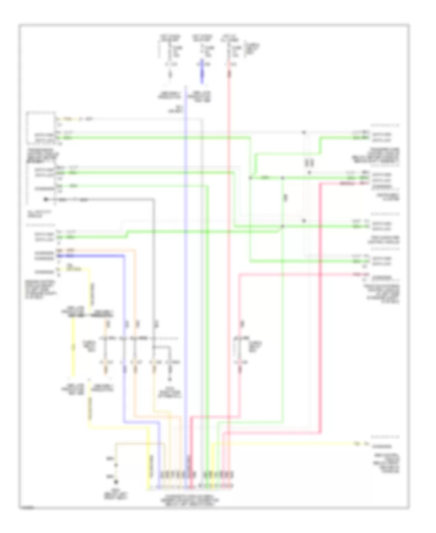
Электросхема компьютерной линии передачи данных CAN для Mercedes-Benz ML430 1999 - Список элементов:
- 1998 early production
- 1998 late production and 1999
- A12
- All activity module
- B10
- B11
- B13
- C/b
- C/c
- C/e
- C/f
- Data high
- Data low
- Diagnosis
- Diagnostic module (obdii) generic scantool connector (below left side of dash)
- Engine control module (me-sfi) (in left side of engine compt, in "e" box)
- Fuse & relay box
- Fuse 10a
- Fuse 15a
- G123 (right side of firewall)
- G203 (below left front seat)
- Hot at all times
- Hot in run or start
- Instrument cluster
- Mr/d
- Mr/e
- Nca
- P/b
- P/c
- Pnk
- Red
- Srs control module (below front center of console)
- Tan
- Traction systems control module (in left side of engine compt, in "e" box)
- Transfer case control module (below center console, behind shift assembly)
- Transmission control module (behind center of dash)
- Trip computer control module
 Русский