TRANSMISSION
A/T Wiring Diagram for Chevrolet Venture 2005
 https://portal-diagnostov.com/license.html
Automotive Electricians Portal FZCO
Automotive Electricians Portal FZCO
https://portal-diagnostov.com/license.html
https://portal-diagnostov.com/license.html
Automotive Electricians Portal FZCO
Automotive Electricians Portal FZCO
List of elements for A/T Wiring Diagram for Chevrolet Venture 2005:
- (fuel injector harn, near breakout for c102)
- (in engine harness, near breakout for powertrain control module)
- 1-2 shift sol
- 2-3 shift sol
- 2-3 shift sol valve
- 5v reference a
- A/t sensor hi
- A/t sensor lo
- Automatic transmission
- Automatic transmission fluid pressure manual valve position switch
- Automatic transmission fluid temperature sensor
- Automatic transmission input shaft speed sensor
- Battery in
- Data link connector (dlc) (below steering column, on knee bolster)
- Ecm sense fuse 10a
- Ect sensor in
- Engine coolant temperature (ect) sensor (on top left rear of engine)
- G113 (in engine compt, left of starter)
- Hot at all times
- Hot in run, bulb test or start
- I/p fuse block (right side of dash, in right front door opening)
- Ign
- Ign 0
- Ign 1
- Ign 1 fuse 10a
- Ignition in
- Instrument panel cluster
- Logic
- Manifold absolute pressure (map) sensor (on top right side of engine)
- Map sensor return
- Mil ctrl
- Pc sol hi
- Pc sol lo
- Pcm ground
- Pcm/ passkey/ cluster fuse 10a
- Pnk
- Power distribution system
- Powertrain control module (pcm) (secured in air cleaner assembly, left front of engine compt)
- Pressure control sol valve
- Red
- S106
- S106 (in engine harness, near breakout for powertrain control module)
- S110
- S115
- S209 (in dash harness, near breakout for security indicator light)
- S210 (in dash harness, near breakout for security indicator light)
- Ser class ii data
- Service engine soon ind
- Sp205
- Stoplamp switch (mounted on top of brake pedal support)
- Tan
- Tcc fuse 10a
- Tcc pwm sol
- Tcc pwm sol valve
- Tcc rel switch
- Tcc release in
- Tcc/ brake switch
- Tcc/brake sw in
- Tft sensor gnd
- Tft sensor in
- Throttle position (tp) sensor (on throttle body assembly)
- Tp sensor in
- Tp sensor return
- Tr sw in-a
- Tr sw in-b
- Tr sw in-c
- Tr sw in-p
- Transmission internal mode switch (ims)
- Underhood fuse block (above battery)
- Vehicle speed sensor (vss) (mounted to right side of transaxle)
- Vss hi (signal)
- Vss lo (ground)
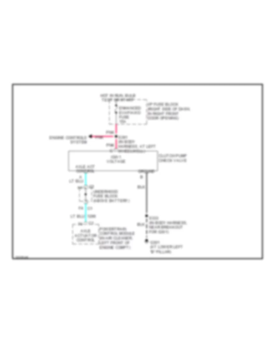
Rear Differential Lock Wiring Diagram for Chevrolet Venture 2005
List of elements for Rear Differential Lock Wiring Diagram for Chevrolet Venture 2005:
- "b" pillar)
- Axle act control
- Axle actuator control
- Clutch pump check valve
- Engine controls system
- Enhanced evap/awd fuse 15a
- F4 c1
- G301 (at lower left
- Ground
- Hot in run, bulb test or start
- I/p fuse block (right side of dash, in right front door opening)
- Ign 1 voltage
- Near breakout for g301)
- Pnk
- Powertrain control module (in air cleaner, left front of engine compt)
- S391 (in body harness, at left wheelwell)
- Underhood fuse block (above battery)

 Čeština
 Dansk
Dansk Deutsch
 Ελληνικά
 English
 English
 Español
 Suomi
Suomi Français
 Français
 עברית
עברית Hrvatski
 Magyar
 Italiano
 日本語
日本語 한국어
한국어 Nederlands
 Polski
 Português
 Português
 Română
 Slovenčina
 Slovenščina
 Svenska
 Türkçe
 中文 (中国)