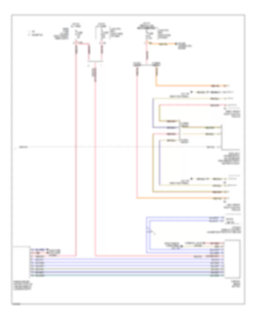
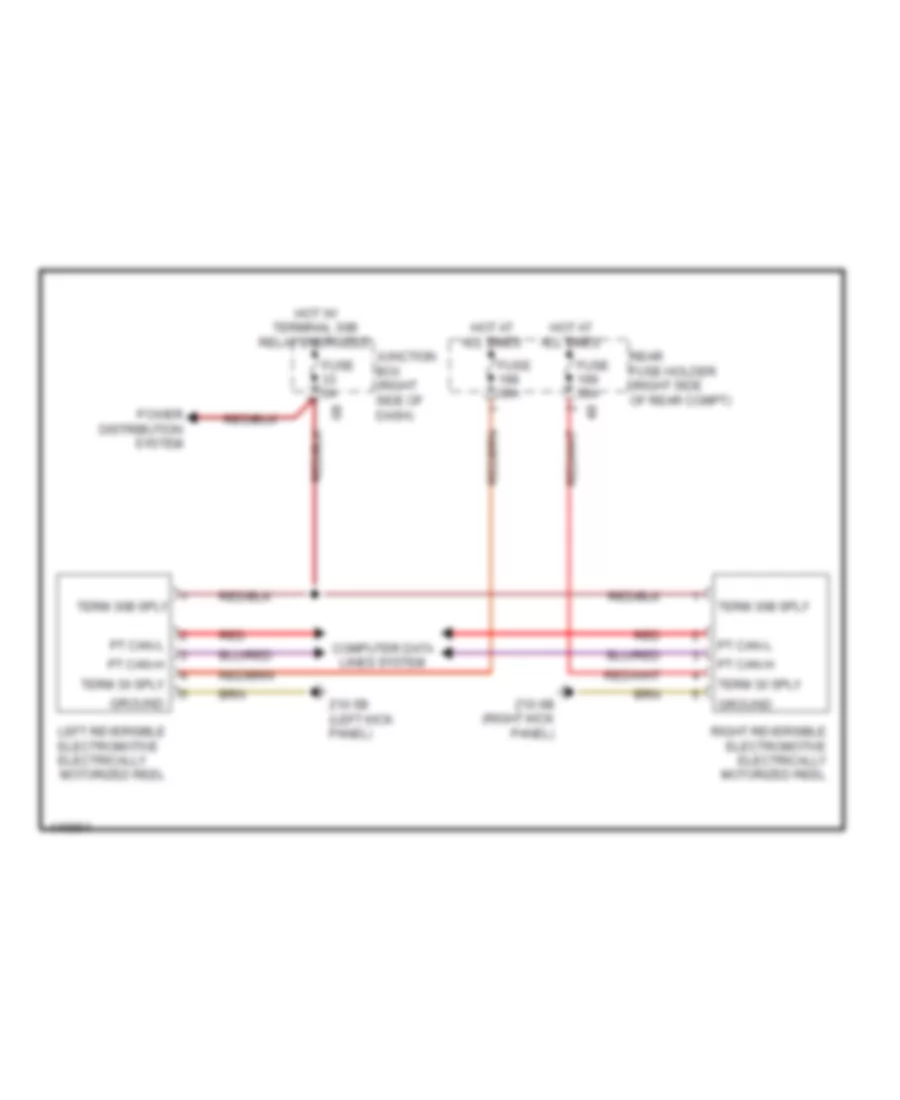
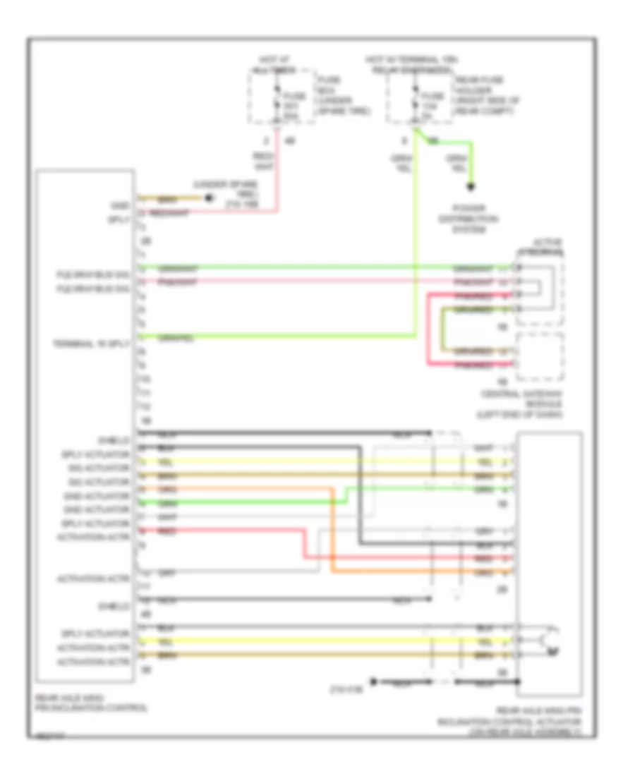
ACTIVE BODYWORKS
Active Bodyworks Wiring Diagram for BMW 535i GT 2014
 https://portal-diagnostov.com/license.html
Automotive Electricians Portal FZCO
Automotive Electricians Portal FZCO
https://portal-diagnostov.com/license.html
https://portal-diagnostov.com/license.html
Automotive Electricians Portal FZCO
Automotive Electricians Portal FZCO
List of elements for Active Bodyworks Wiring Diagram for BMW 535i GT 2014:
- (right side of cargo area) z10 8b
- 30b
- Fully automatic towing hitch button
- Fully automatic towing hitch drive
- Fuse 20a
- Gnd
- Hall sens sig
- Hot w/ terminal 30b relay energized
- Led activation
- Nca
- Rear fuse holder (right side of rear compt)
- Sw sig
- Towing hitch
- Trailer module (under spare tire)
- Trailer socket switch
- X268 1b
- X269 1b
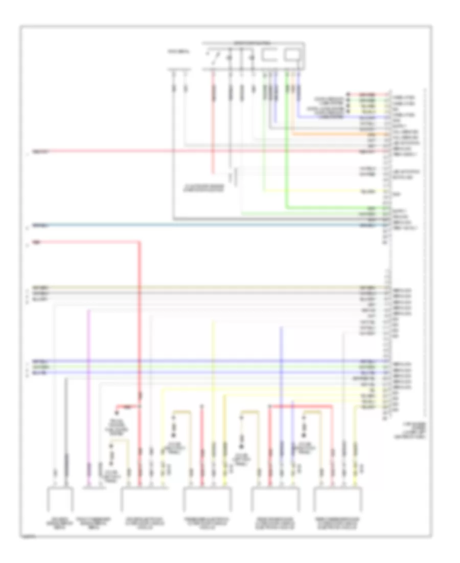
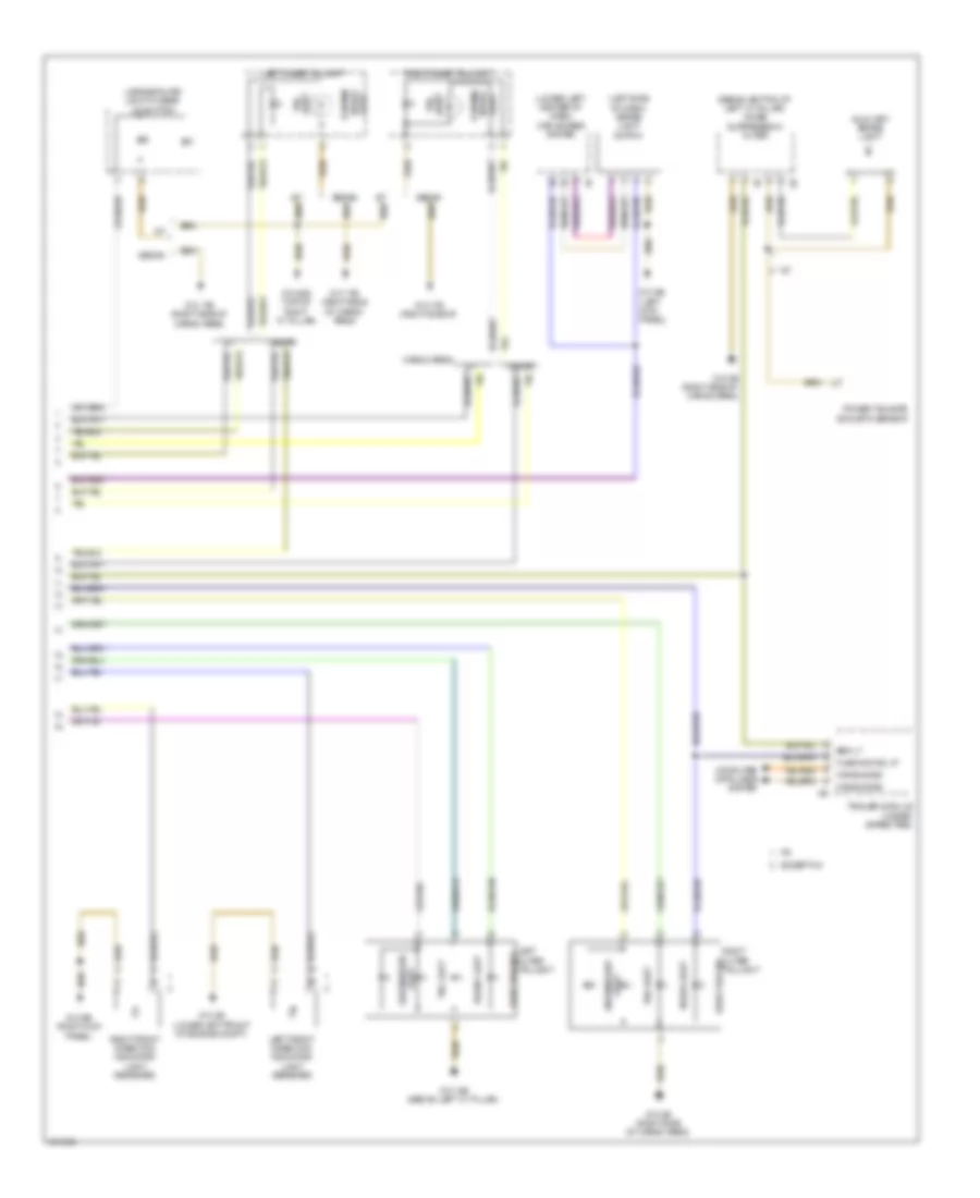
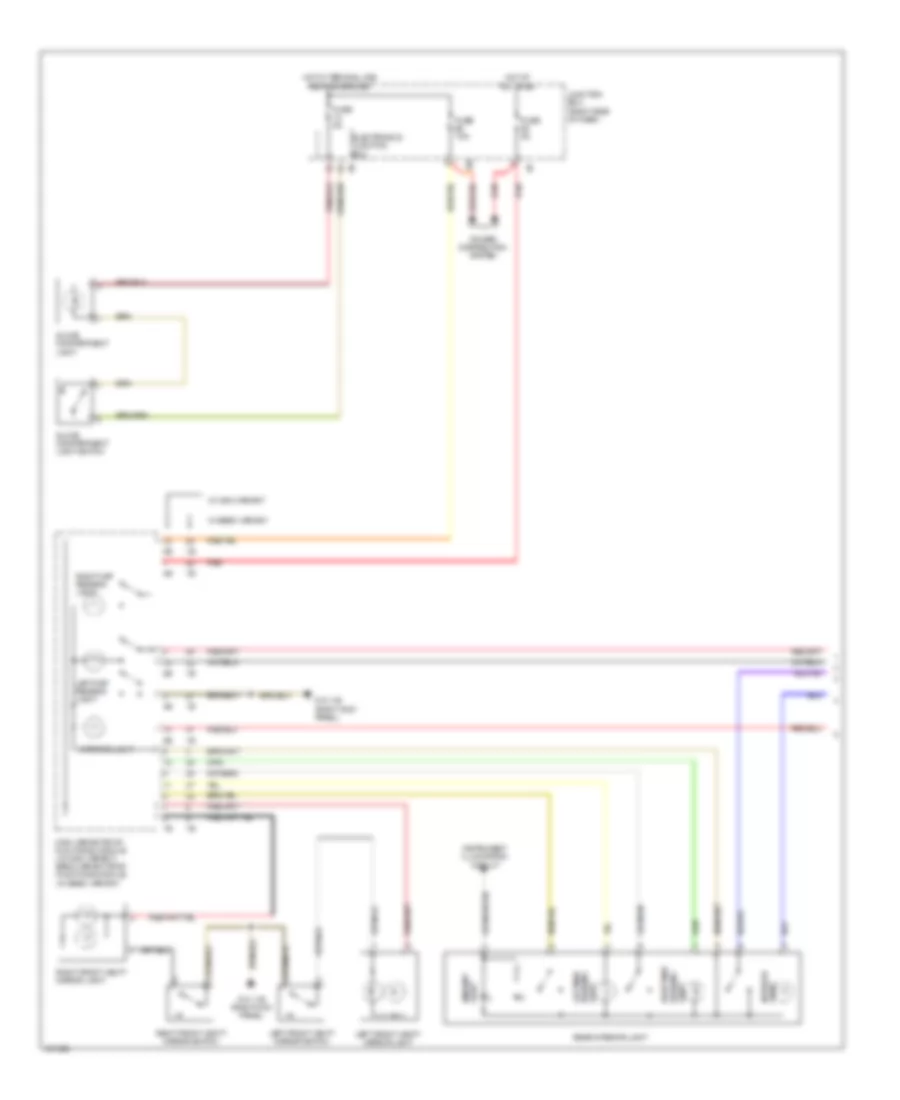
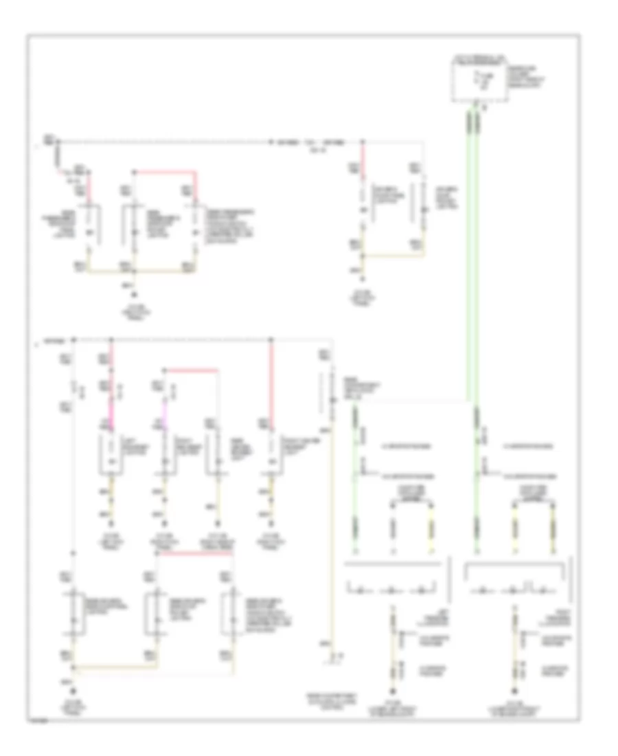
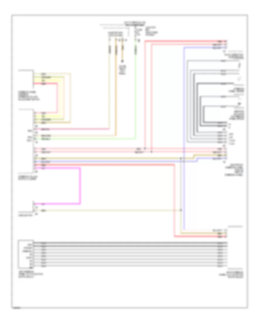
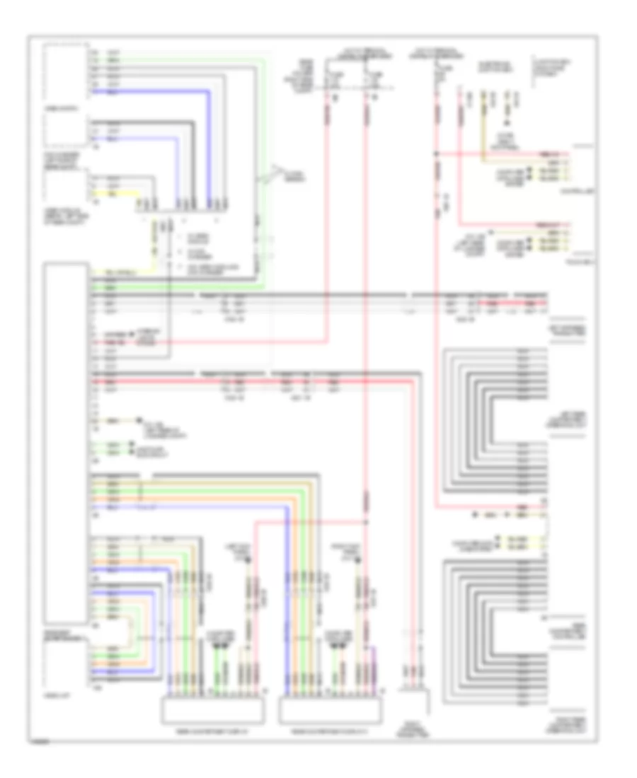
AIR CONDITIONING
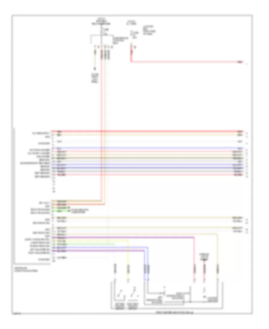
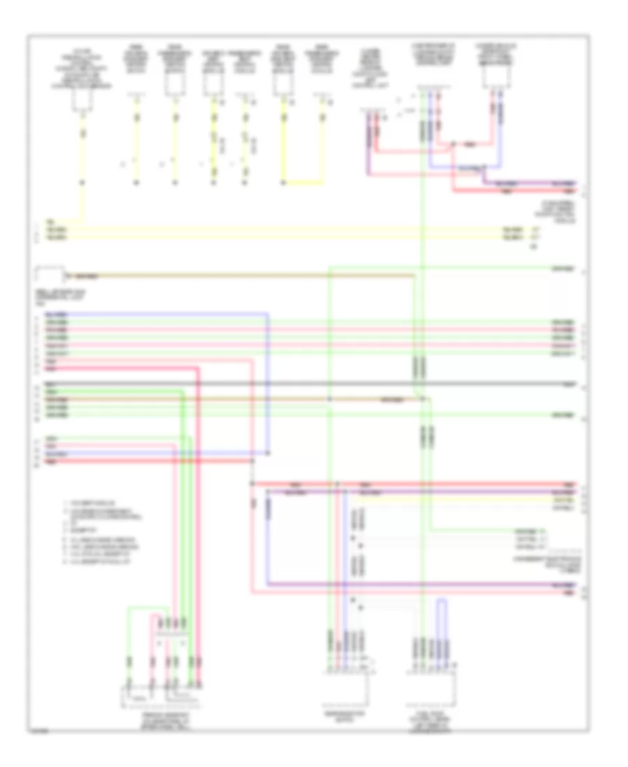
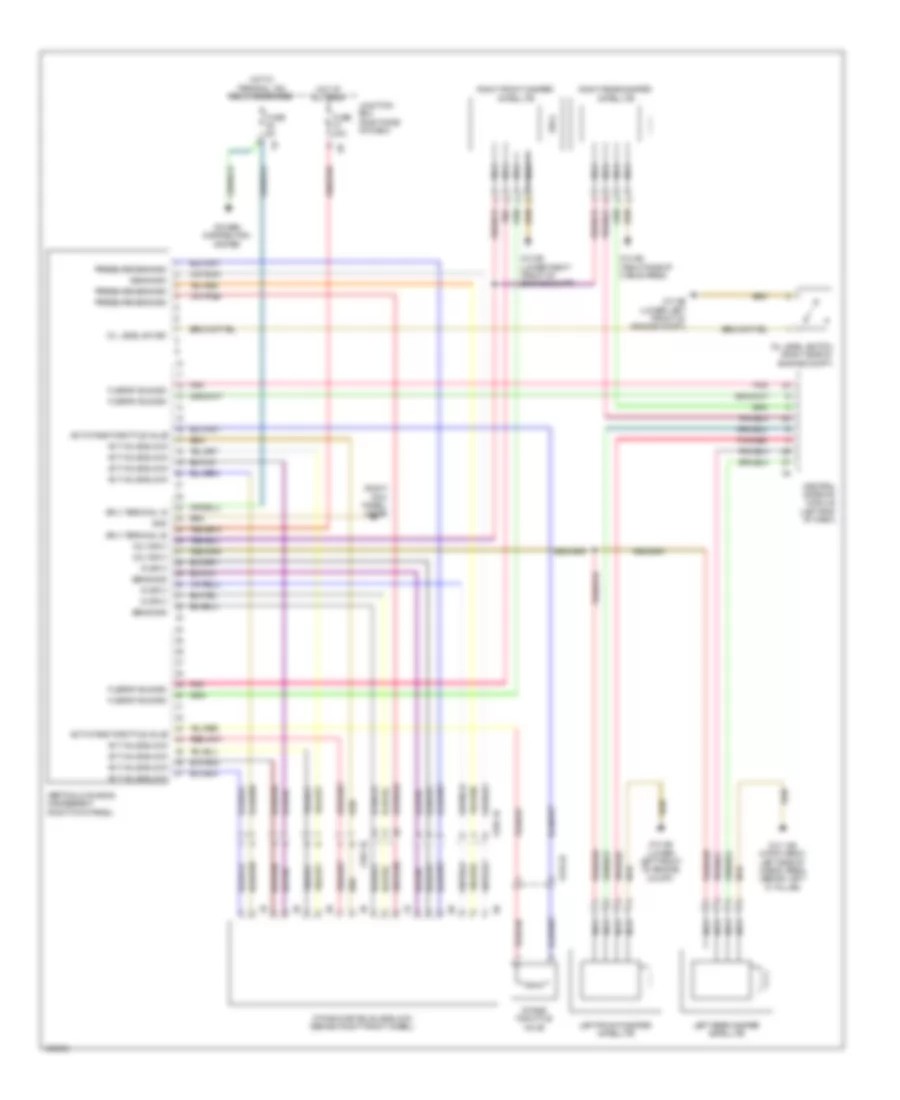
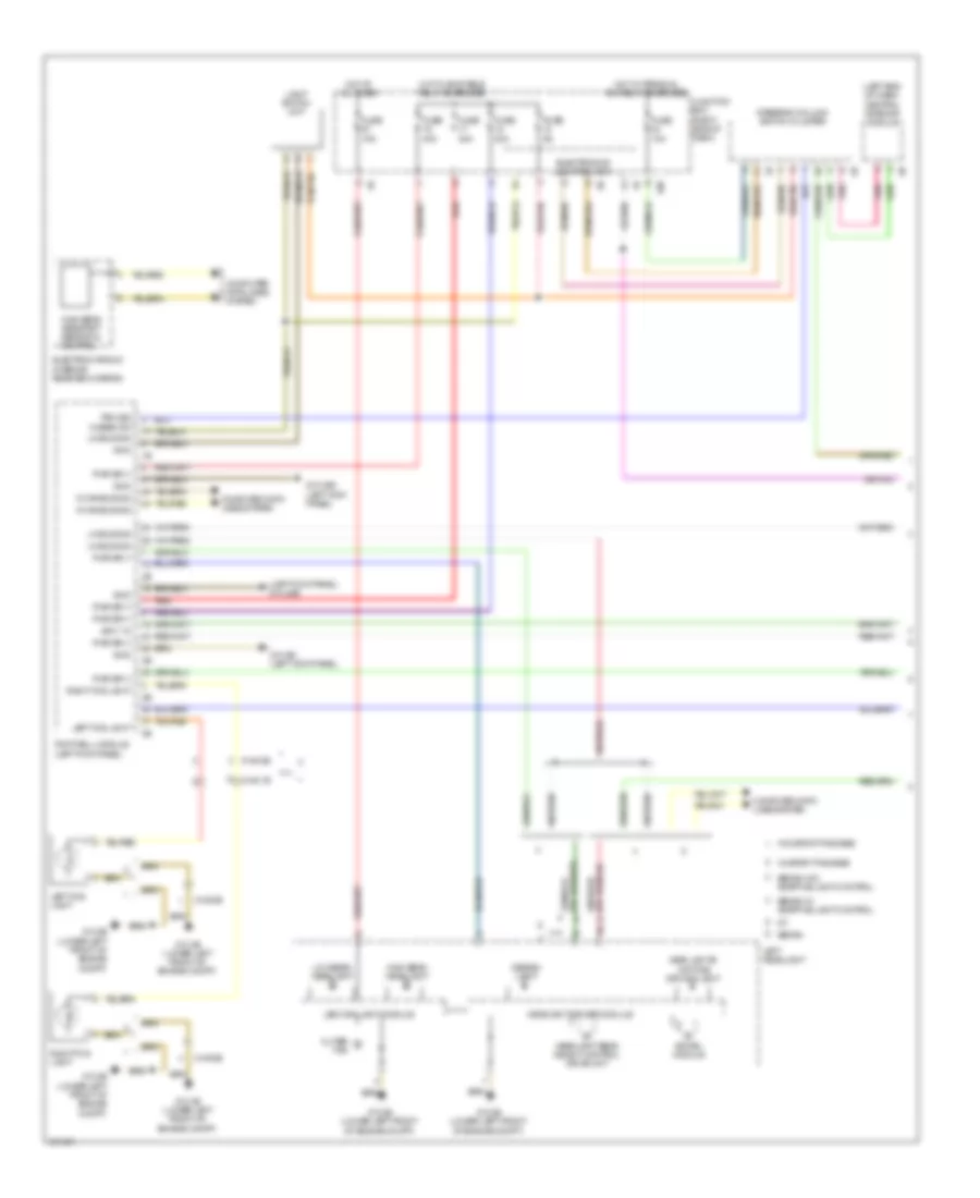
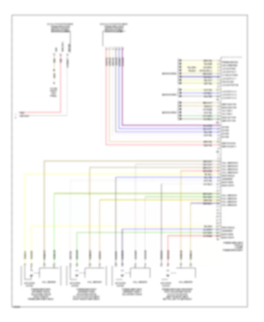
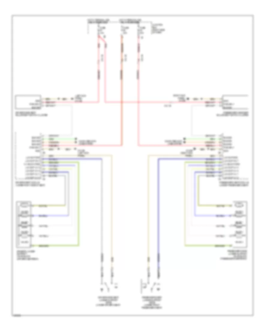
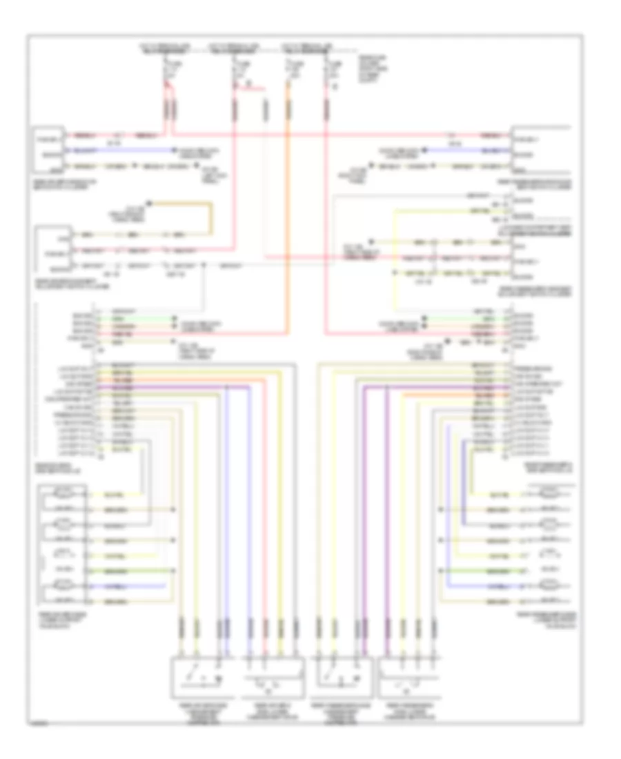
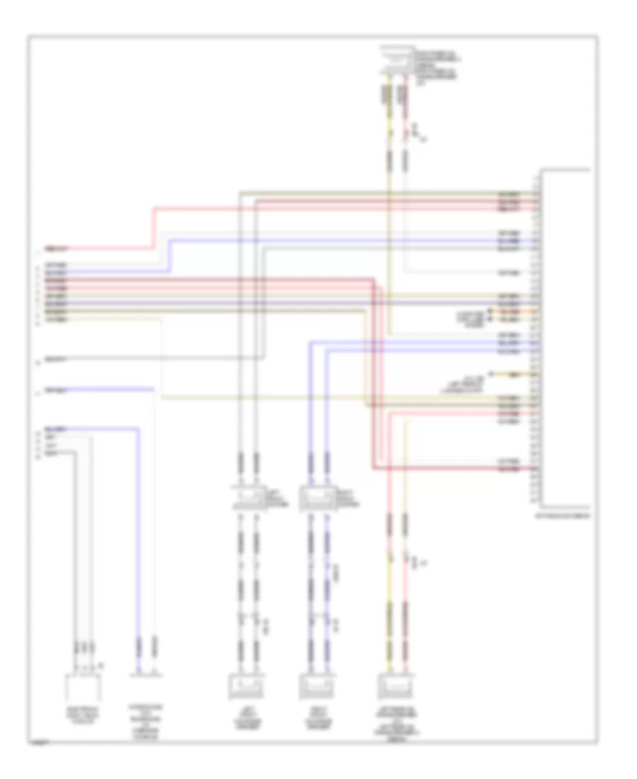
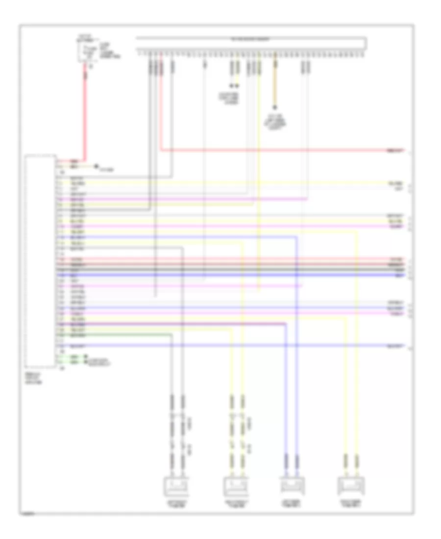
Automatic A/C Wiring Diagram, with Rear Automatic Climate Control (1 of 4) for BMW 535i GT 2014
List of elements for Automatic A/C Wiring Diagram, with Rear Automatic Climate Control (1 of 4) for BMW 535i GT 2014:
- 535i gt, 535i gt xdrive & w/ fan 400/600w
- 535i gt, 535i gt xdrive, w/ fan 800/1000w &
- 550i gt, 550i gt xdrive
- Activation ioniser
- Auc sensor (on air recirculation control microfilter compt)
- Body can bus sig
- Computer data lines system
- Electric fan cutoff relay (right side of luggage compt)
- Electronics junction box
- End pos sw sig
- End position switch
- Front center ventilation grille
- Front power distribution box
- Fuse 100a
- Fuse 5a
- Fuse 60a
- Fuse 7.5a
- Fuse box (under spare tire)
- Gnd
- Gnd ioniser
- Heating/air conditioning system
- Hot at all times
- Hot w/ bi-stable relay energized
- Hot w/ terminal 15n relay energized
- Hot w/ terminal 30b relay energized
- Interior lights system
- Ionizer (on heating & air conditioning unit)
- Junction box (right side of dash)
- Left adjuster sig
- Left end position switch
- Left stratification actuator
- Lh end pas sw sig
- Lin bus sig
- Locator lighting
- Power distribution system
- Rear fuse holder (right side of rear compt)
- Red
- Refrigerant pressure sensor (on high pressure line to evaporator)
- Rh end pas sw sig
- Right adjuster sig
- Right end position switch
- Right front ventilation grille
- Right stratification actuator
- Sens gnd
- Sens sig
- Sig evaporator temp sens
- Sply volt
- Temp sens
- Z10 11b (right kick panel)
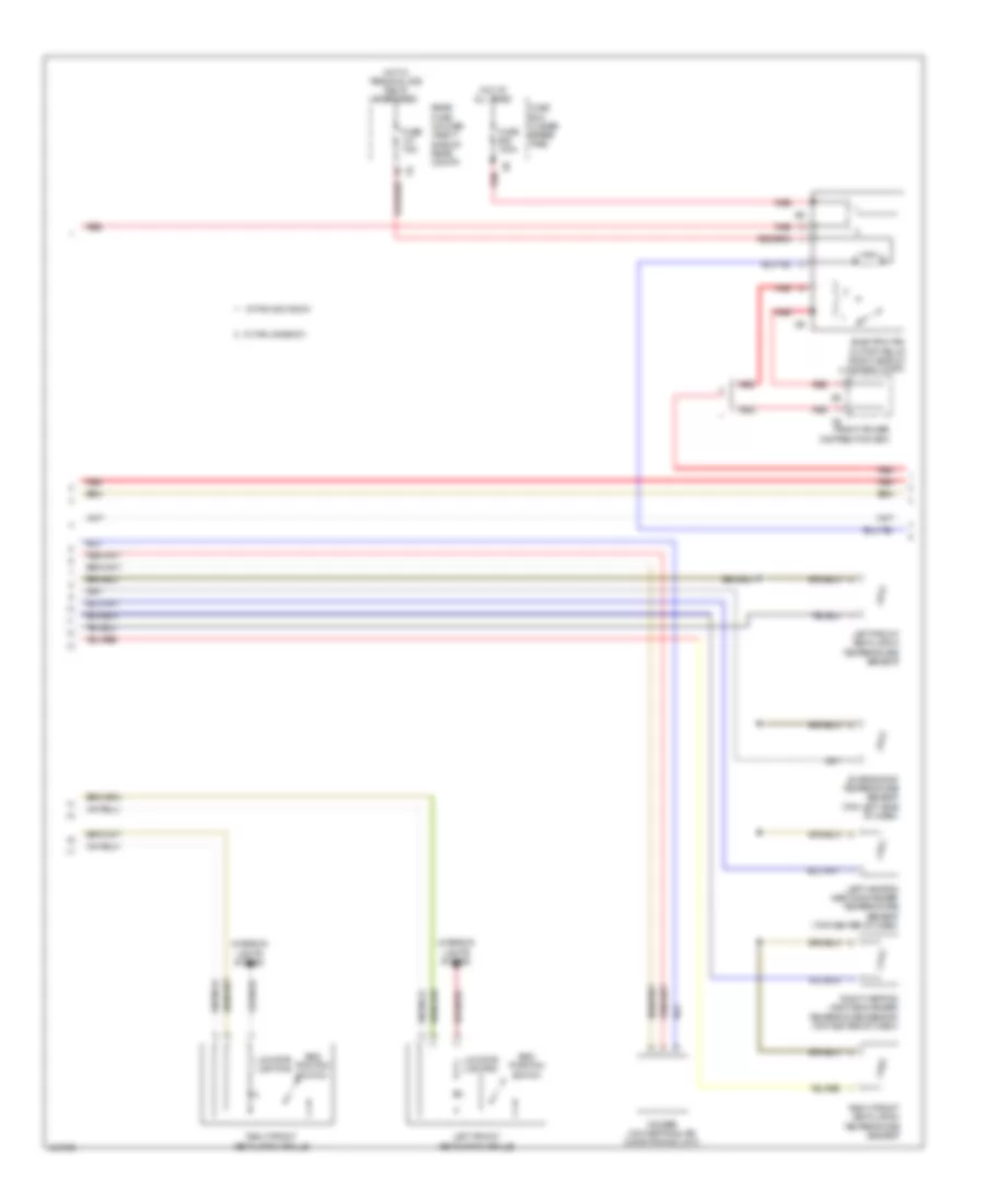
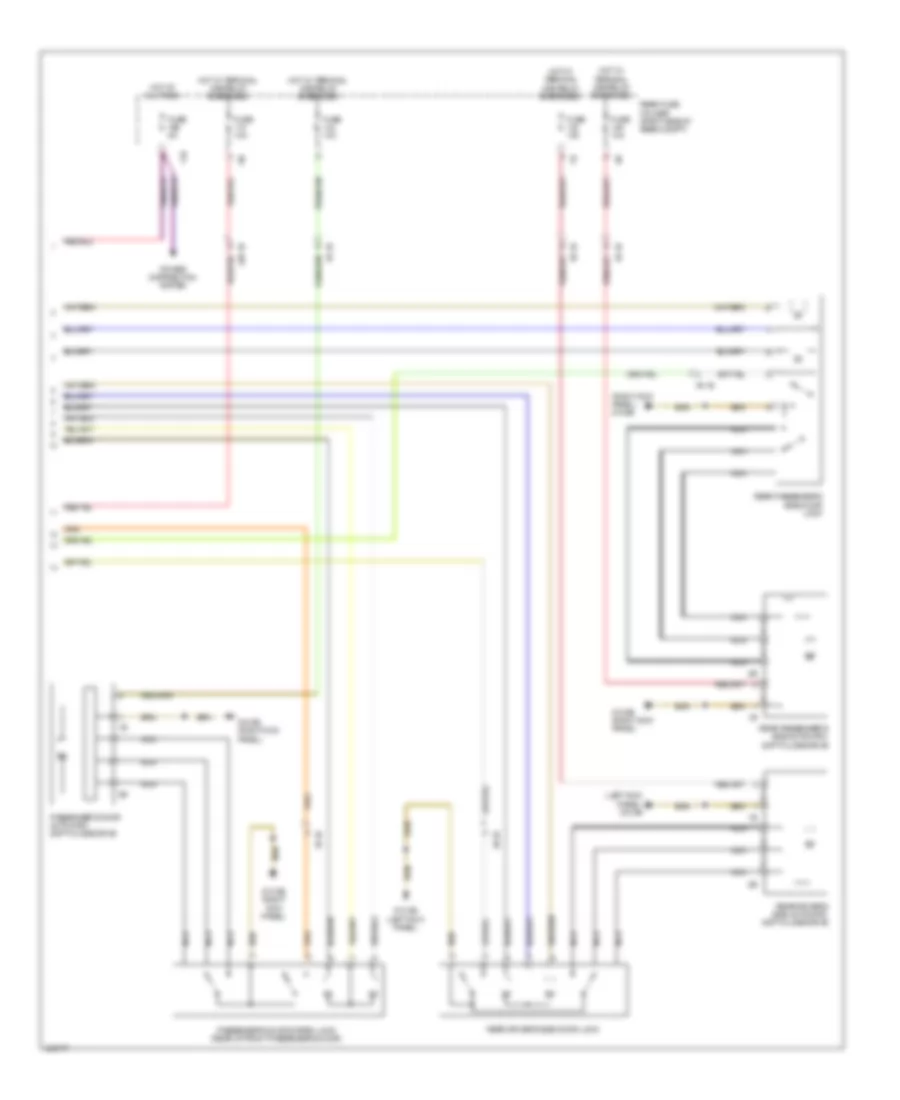
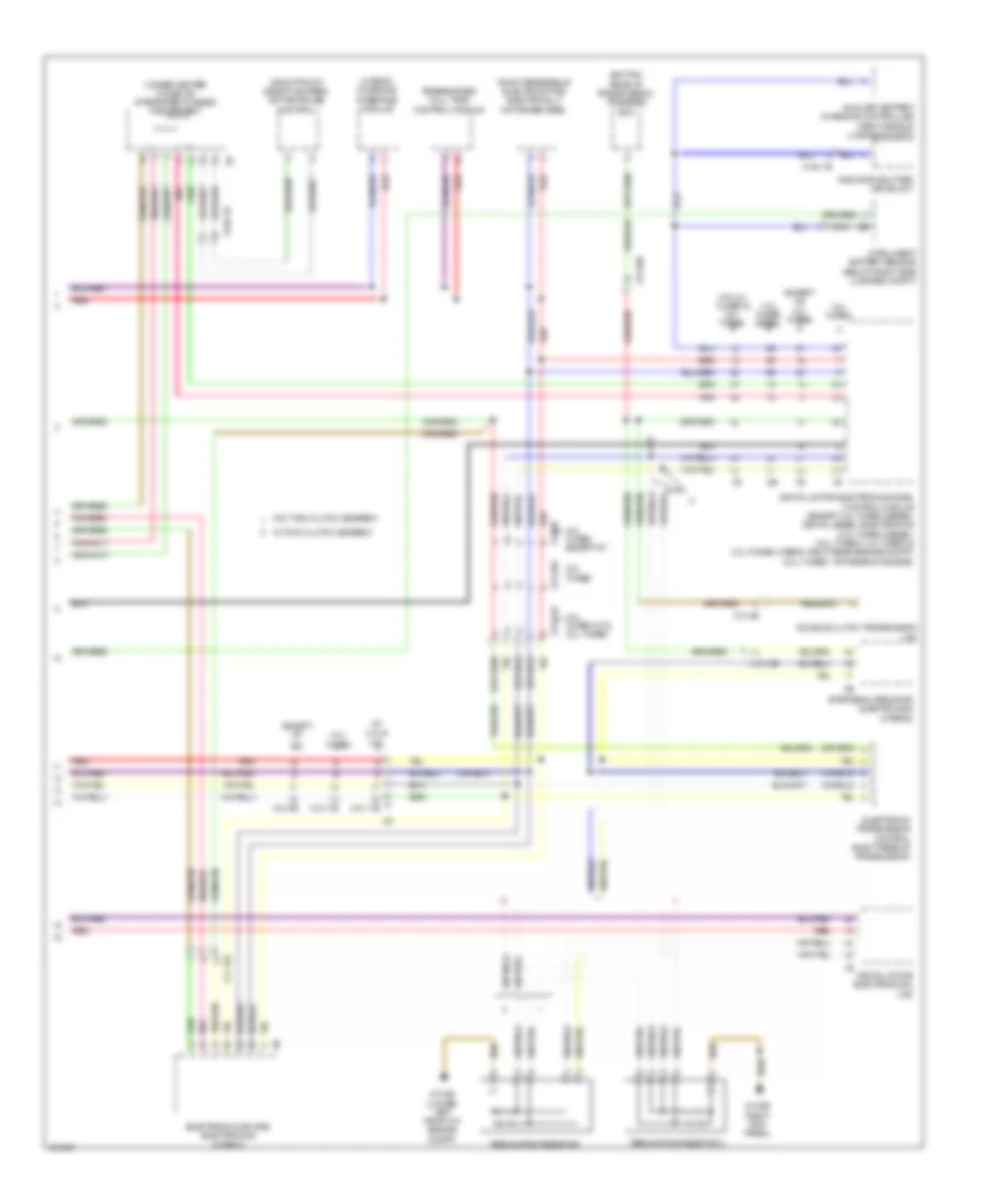
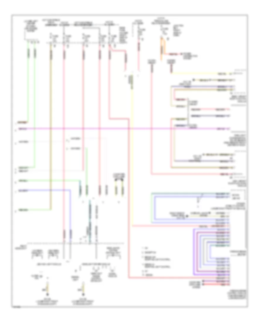
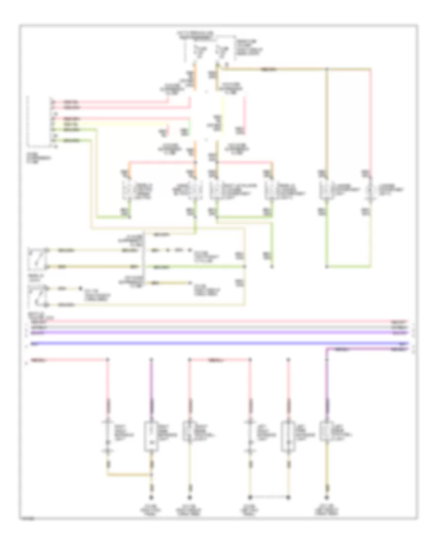
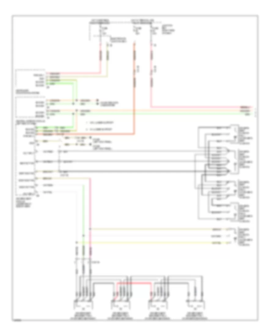
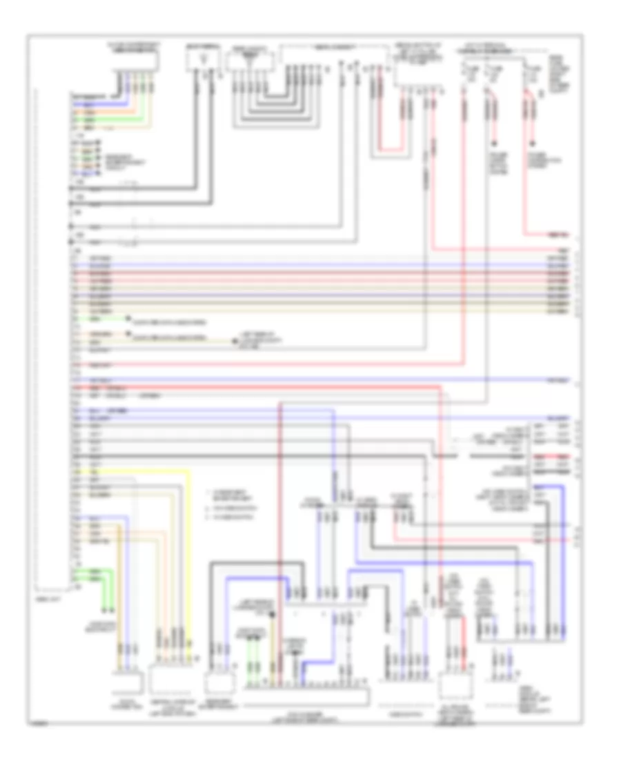
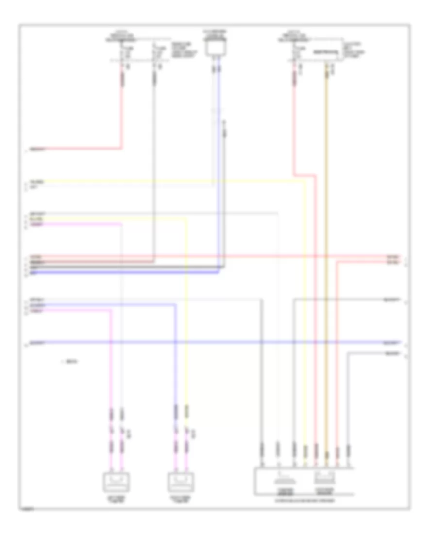
Automatic A/C Wiring Diagram, with Rear Automatic Climate Control (2 of 4) for BMW 535i GT 2014
List of elements for Automatic A/C Wiring Diagram, with Rear Automatic Climate Control (2 of 4) for BMW 535i GT 2014:
- 535i gt & 535i gt xdrive
- 550i gt & 550i gt xdrive
- Characteristic map thermostat (front of engine)
- Computer data lines system
- Digital motor electronics (right rear engine compt)
- Electric coolant pump (535i gt & 535i gt xdrive) (left side of engine)
- Electric fan (right front side of engine compt)
- End position switch
- Engine coolant temperature sensor (4.4l turbo: front of engine)
- Fuse 10a
- Fuse 50a (or 30a)
- Fuse 5a
- Hot at all times
- Hot w/ terminal 15n relay energized
- Intercooler coolant pump (550i gt & 550i gt xdrive)
- Interior lights system
- Junction box (right side of dash)
- Left front ventilation grille
- Locator lighting
- Nca
- Power distribution box (in engine compt)
- Radiator outlet temperature sensor (550i gt & 550i gt xdrive) (right front of engine compt)
- Radiator shutter drive unit
- Radiator shutter solenoid (550i gt & 550i gt xdrive)
- Red
- Turbocharger coolant pump (550i gt & 550i gt xdrive) (behind charge air cooling expansion tank)
- X148 1b
- X671 1b
- X697 1b
- X705 1b
- Z10 15b (left rear of engine compt)
- Z10 2b (lower left front of engine compt)
- Z6000 4b
- Z6000 5b
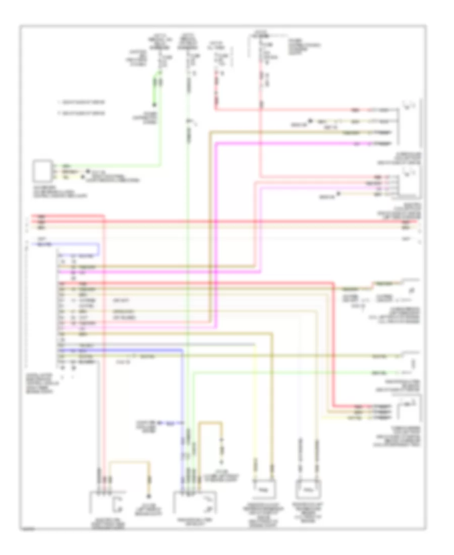
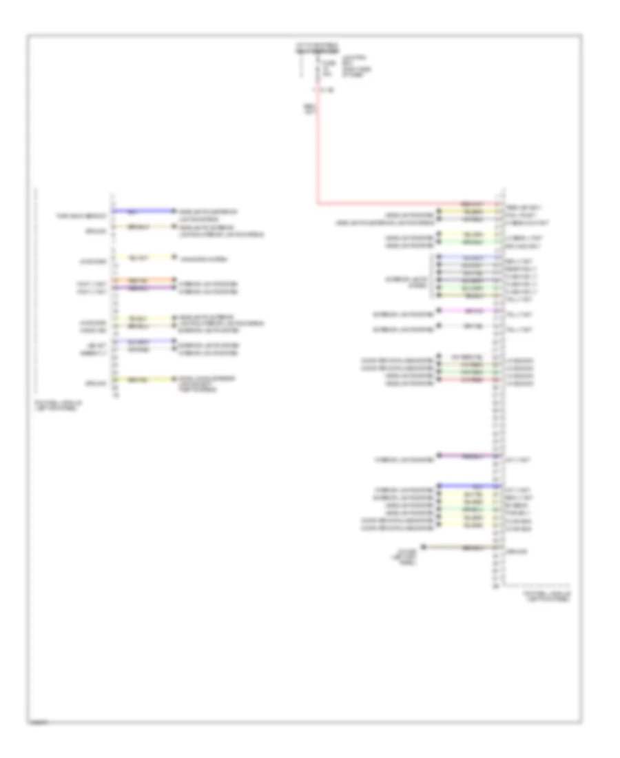
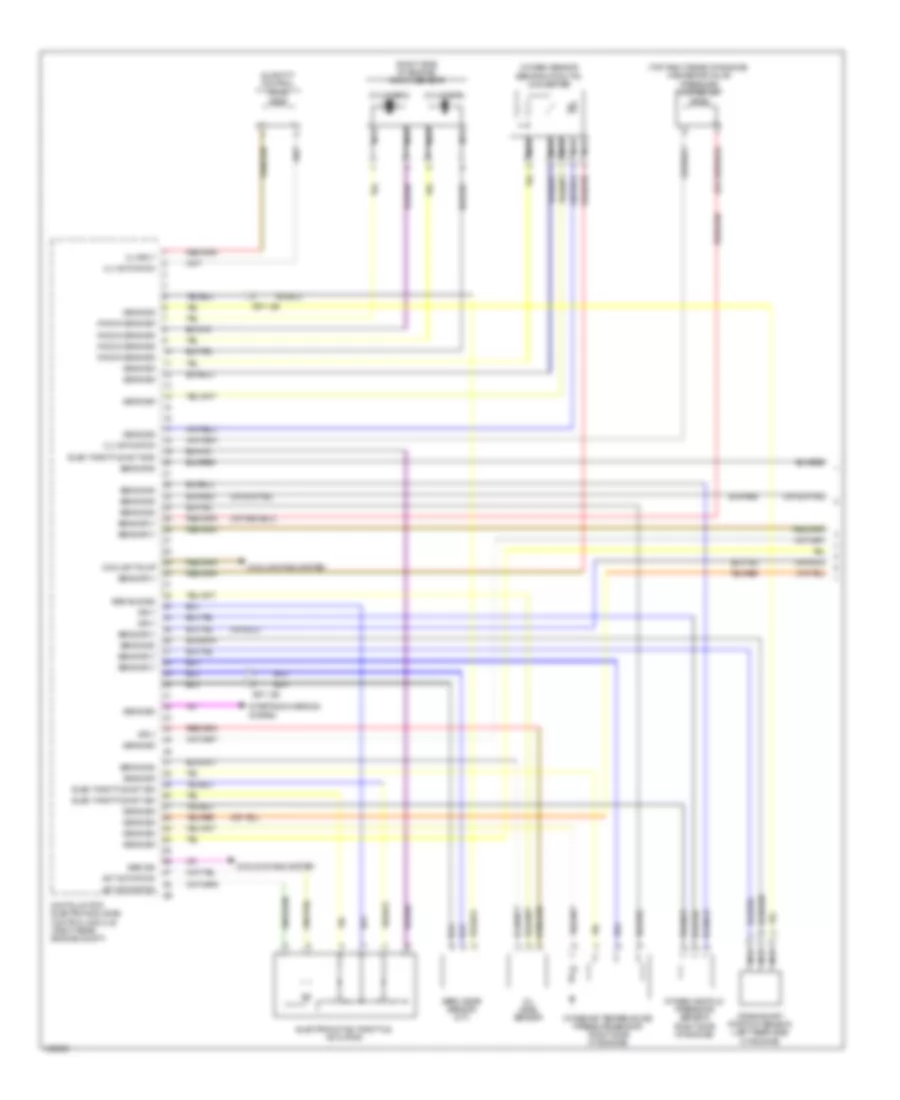
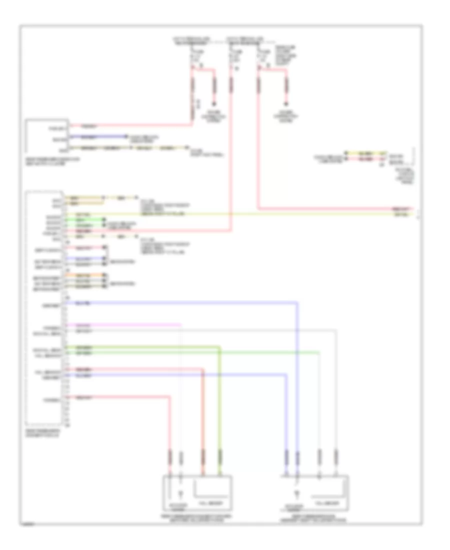
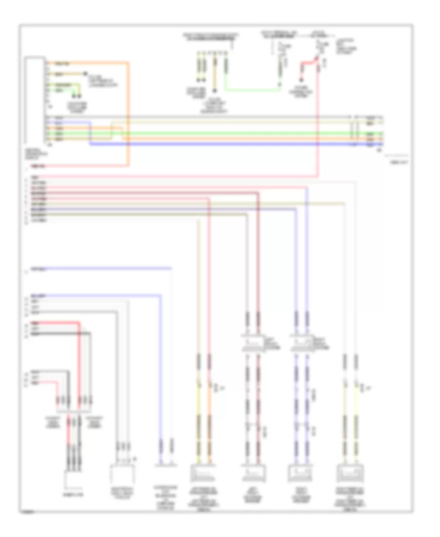
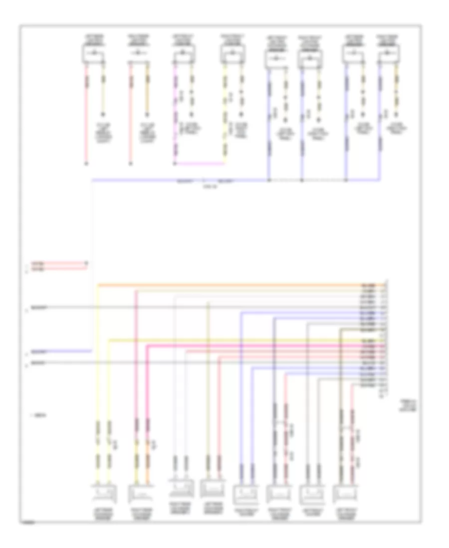
Automatic A/C Wiring Diagram, with Rear Automatic Climate Control (3 of 4) for BMW 535i GT 2014
List of elements for Automatic A/C Wiring Diagram, with Rear Automatic Climate Control (3 of 4) for BMW 535i GT 2014:
- 12b
- Activation output
- Computer data lines system
- Evaporator temperature sensor (top left side of dash)
- Fuse 20a
- Fuse 30a
- Fuse 5a
- Gnd
- Hot at all times
- Hot w/ terminal 30b relay energized
- Interior lights system
- Junction box (right side of dash)
- K-can bus sig
- Left front ventilation temperature sensor
- Left heating heat exchanger temperature sensor (top center of dash)
- Left rear compartment footwell temperature sensor (on rear automatic heater/air conditioner)
- Left rear compartment stratification actuator
- Left rear compartment ventilation temperature sensor
- Left rear electric auxiliary heater
- Left sig temp sens
- Locator lighting
- Lr aux htr
- Nca
- Rear compartment automatic climate control
- Rear compartment blower motor
- Rear compartment fan motor output stage (on rear compt fan motor)
- Rear compartment ventilation grille
- Rear fuse holder (right side of rear compt)
- Red
- Right front ventilation temperature sensor
- Right heating heat exchanger temperature sensor (top center of dash)
- Right rear compartment footwell temperature sensor (on rear automatic heater/air conditioner)
- Right rear compartment stratification actuator
- Right rear compartment ventilation temperature sensor
- Right rear electric auxiliary heater
- Right sig temp sens
- Rr aux htr
- Sens gnd
- Sig
- Sig right sig stratification adjuster
- Sply
- Sply volt
- Z10 11b (right kick panel)
- Z10 5b (left kick panel)
- Z10 6b (right kick panel)
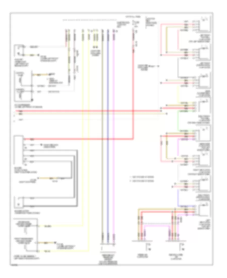
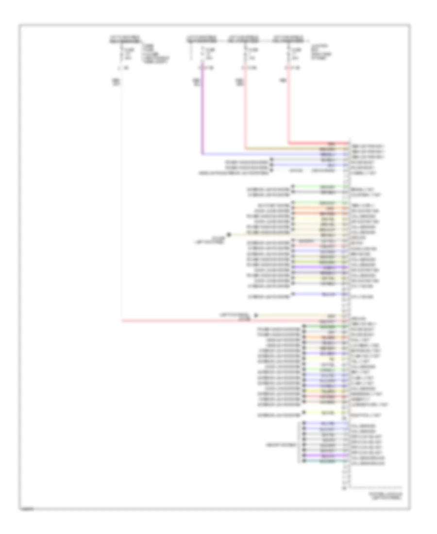
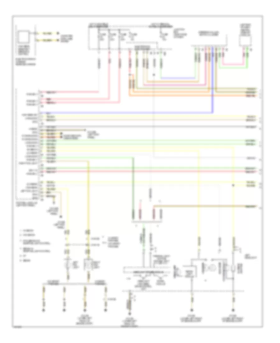
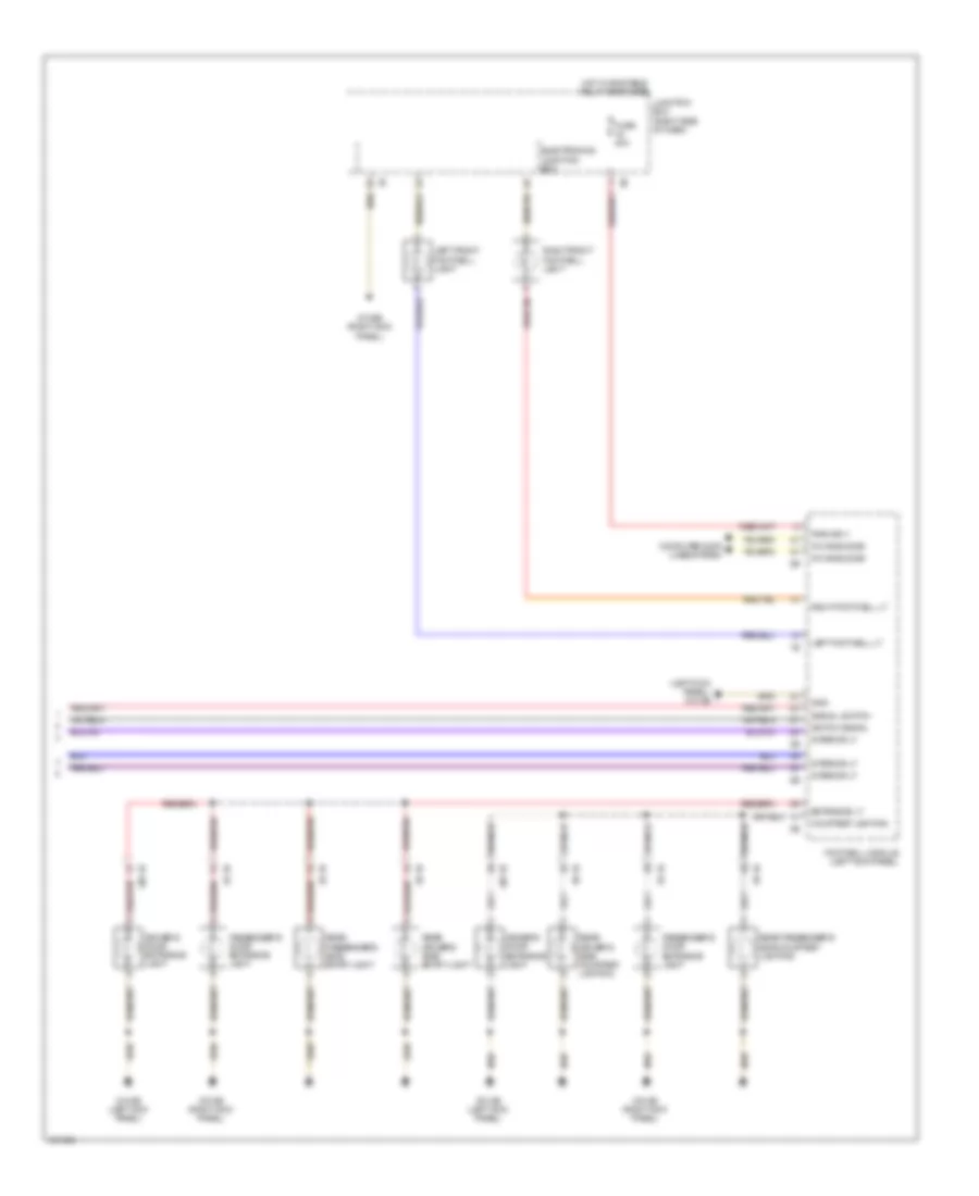
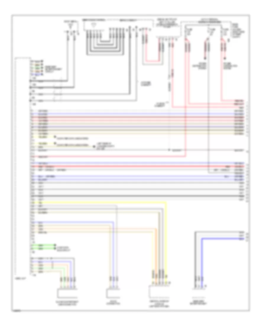
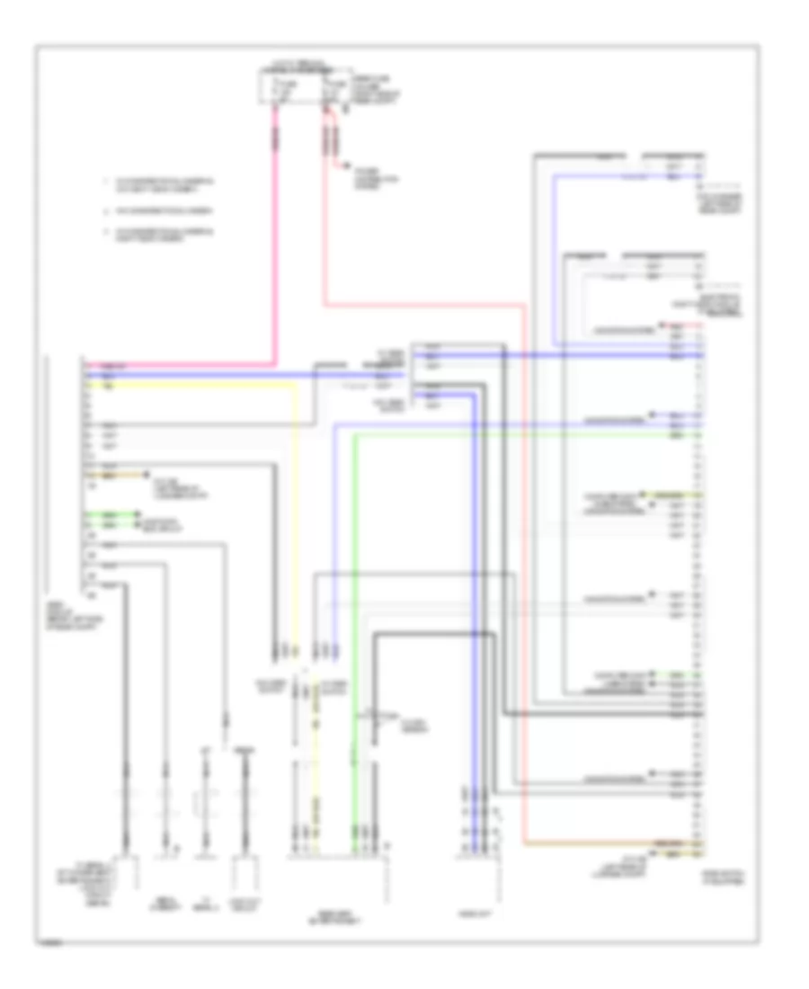
Automatic A/C Wiring Diagram, with Rear Automatic Climate Control (4 of 4) for BMW 535i GT 2014
List of elements for Automatic A/C Wiring Diagram, with Rear Automatic Climate Control (4 of 4) for BMW 535i GT 2014:
- (535i gt & 535i gt xdrive: rear of engine block) (550i gt & 550i gt xdrive) x6460 (535i gt & 535i gt xdrive) x6454
- 13b
- 535i gt & 535i gt xdrive
- 550i gt & 550i gt xdrive
- A/c compressor (lower left front of engine)
- Auxiliary water pump (left front of engine compt)
- Blower motor (under right side of dash)
- Blower output stage (next to blower motor)
- Computer data lines system
- Control valve
- Defroster flap motor (top left side of dash)
- Driver side heat exchanger water valve
- Electronics junction box
- Fresh air flap motor
- Front passenger's heat exchanger water valve
- Fuse 40a
- Hot at all times
- Junction box (right side of dash)
- Left center ventilation flap motor
- Left front footwell flap motor (top left side of dash)
- Left front stratification flap motor
- Left outer ventilation flap motor
- Left rear compartment footwell flap motor
- Left rear stratifying air flap motor
- Magnetic clutch
- N2 1b
- Nca
- Recirculated air flap motor
- Red
- Right center ventilation flap motor
- Right front footwell flap motor (top right side of dash)
- Right front stratification flap motor
- Right outer ventilation flap motor
- Right rear compartment footwell flap motor
- Right rear stratifying air flap motor
- Water valve assembly (left side of engine compt)
- X01001
- X13 10b
- X13 1b
- Z10 2b (lower left front of engine compt)
- Z10 6b (right kick panel)
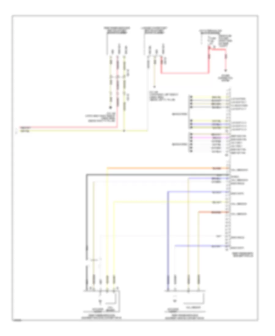
Automatic A/C Wiring Diagram, without Rear Automatic Climate Control (1 of 4) for BMW 535i GT 2014
List of elements for Automatic A/C Wiring Diagram, without Rear Automatic Climate Control (1 of 4) for BMW 535i GT 2014:
- Activation ioniser
- Body can bus sig
- Computer data lines system
- Electronics junction box
- End pos sw sig
- Front center ventilation grille
- Fuse 60a
- Fuse 7.5a
- Gnd
- Gnd ioniser
- Heating/air conditioning system
- Hot at all times
- Hot w/ bi-stable relay energized
- Interior lights system
- Junction box (right side of dash)
- Left adjuster sig
- Left end position switch
- Left stratification actuator
- Lh end pas sw sig
- Lin bus sig
- Locator lighting
- Red
- Rh end pas sw sig
- Right adjuster sig
- Right end position switch
- Right stratification actuator
- Sens gnd
- Sens sig
- Sig evaporator temp sens
- Sply volt
- Temp sens sig
- Z10 6b (right kick panel)
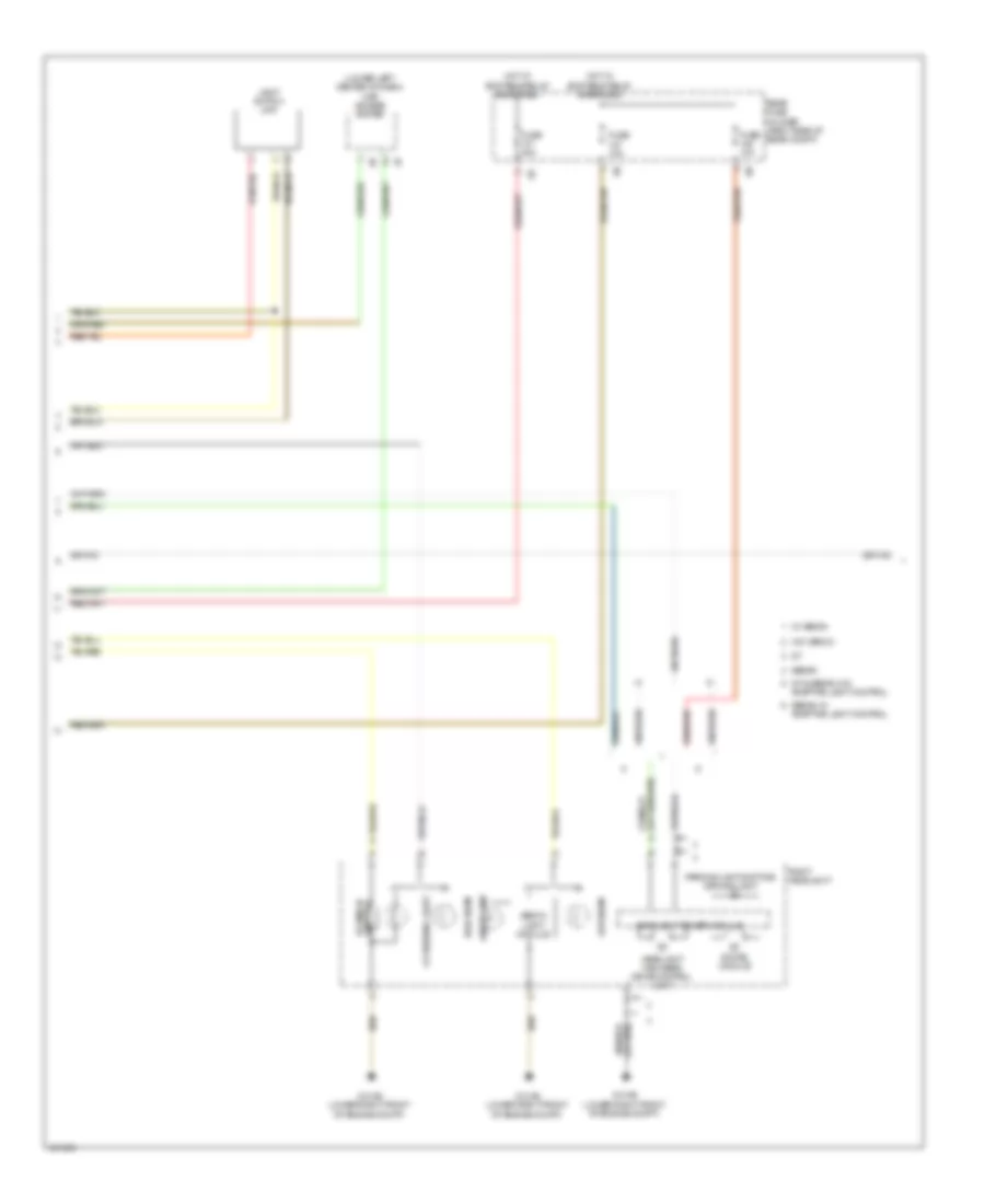
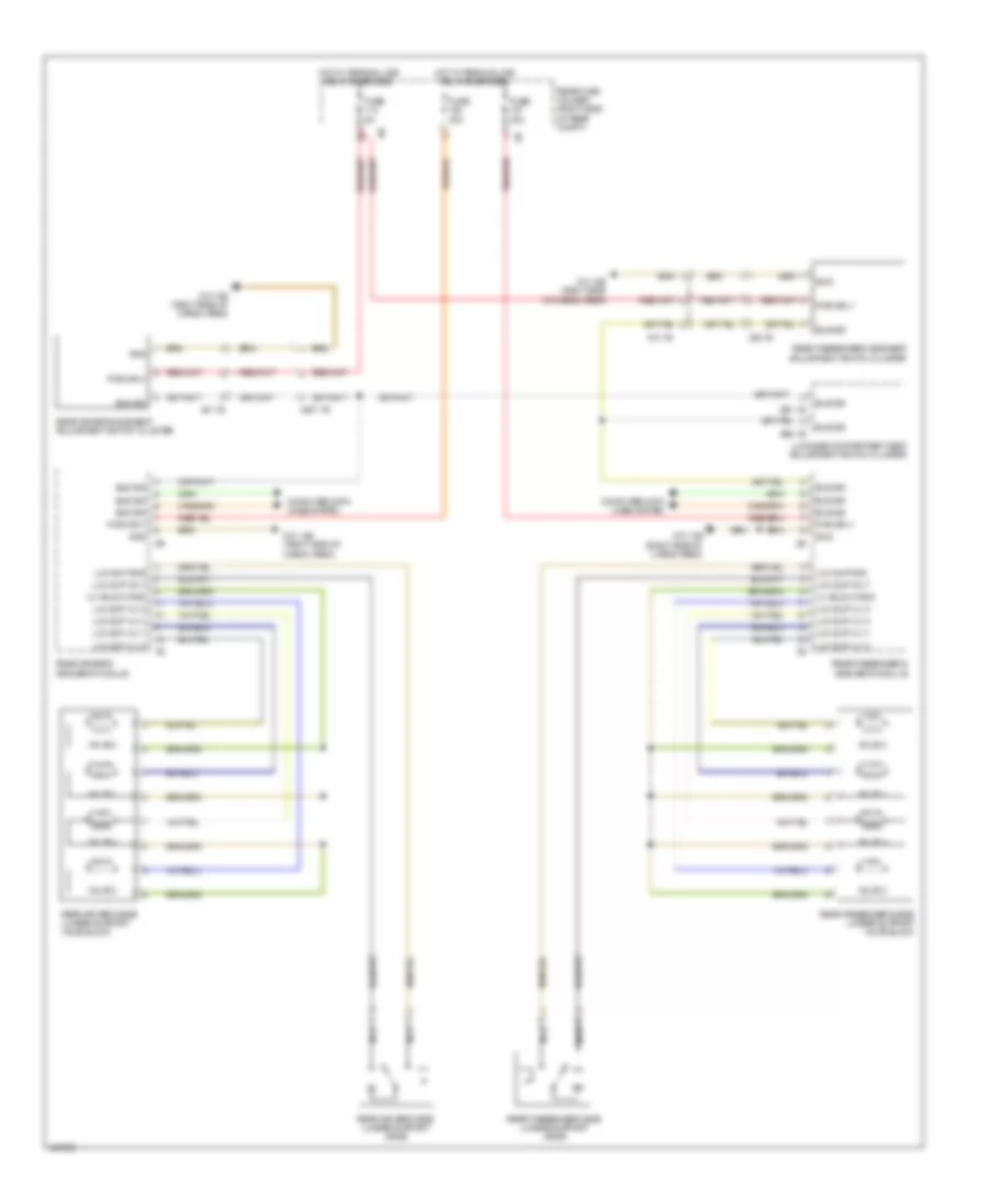
Automatic A/C Wiring Diagram, without Rear Automatic Climate Control (2 of 4) for BMW 535i GT 2014
List of elements for Automatic A/C Wiring Diagram, without Rear Automatic Climate Control (2 of 4) for BMW 535i GT 2014:
- Electric fan cutoff relay (right side of luggage compt)
- End position switch
- Evaporator temperature sensor (top left side of dash)
- Front power distribution box
- Fuse 100a
- Fuse 7.5a
- Fuse box (under spare tire)
- Hot at all times
- Hot w/ terminal 30b relay energized
- Interior lights system
- Ionizer (on heating & air conditioning unit)
- Left front ventilation grille
- Left front ventilation temperature sensor
- Left heating heat exchanger temperature sensor (top center of dash)
- Locator lighting
- Rear fuse holder (right side of rear compt)
- Red
- Right front ventilation grille
- Right front ventilation temperature sensor
- Right heating heat exchanger temperature sensor (top center of dash)
- W/ fan 400/600w
- W/ fan 800/1000w
Automatic A/C Wiring Diagram, without Rear Automatic Climate Control (3 of 4) for BMW 535i GT 2014
List of elements for Automatic A/C Wiring Diagram, without Rear Automatic Climate Control (3 of 4) for BMW 535i GT 2014:
- 535i gt & 535i gt xdrive
- 550i gt & 550i gt xdrive
- Auc sensor (on air recirculation control microfilter compt)
- Characteristic map thermostat (3.0l: left front of engine) (4.4l: front of engine)
- Computer data lines system
- Digital motor electronics control module (right rear engine compt)
- Electric coolant pump (535i gt & 535i gt xdrive) (left side of engine)
- Electric fan (right front side of engine compt)
- Engine coolant temperature sensor (4.4l: front of engine)
- Fuse 10a
- Fuse 30a (or 50a)
- Fuse 5a
- Hot at all times
- Hot w/ terminal 15n relay energized
- Intercooler coolant pump (550i gt & 550i gt xdrive)
- Junction box (right side of dash)
- Nca
- Power distribution box (in engine compt)
- Power distribution system
- Radiator outlet temperature sensor (550i gt & 550i gt xdrive) (right front of engine compt)
- Radiator shutter drive unit
- Radiator shutter solenoid (550i gt & 550i gt xdrive)
- Red
- Turbocharger coolant pump (550i gt & 550i gt xdrive) (behind charge air cooling expansion tank)
- X148 1b
- X671 1b
- X697 1b
- X705 1b
- Z10 11b (right kick panel)
- Z10 15b (left rear of engine compt)
- Z10 2b (lower left front of engine compt)
- Z6000 4b
- Z6000 5b
Automatic A/C Wiring Diagram, without Rear Automatic Climate Control (4 of 4) for BMW 535i GT 2014
List of elements for Automatic A/C Wiring Diagram, without Rear Automatic Climate Control (4 of 4) for BMW 535i GT 2014:
- (rear of engine block)
- 13b
- 535i gt & 535i gt xdrive
- 550i gt & 550i gt xdrive
- A/c compressor (lower left front of engine)
- Auxiliary water pump (left front of engine compt)
- Blower motor (under right side of dash)
- Blower output stage (next to blower motor)
- Computer data lines system
- Control valve
- Defroster flap motor (top left side of dash)
- Driver side heat exchanger water valve
- Electronics junction box
- Fresh air flap motor
- Front passenger's heat exchanger water valve
- Fuse 40a
- Hot at all times
- Junction box (right side of dash)
- Left front footwell flap motor (top left side of dash)
- Left front stratification flap motor
- Left ventilation flap motor (top left side of dash)
- Magnetic clutch
- N2 1b
- Nca
- Rear compartment flap motor
- Recirculated air flap motor
- Red
- Refrigerant pressure sensor (on high pressure line to evaporator)
- Right front footwell flap motor (top right side of dash)
- Right front stratification flap motor
- Right ventilation flap motor (top right side of dash)
- Water valves assembly (left side of engine compt)
- X01001
- X13 10b
- X13 1b
- X6454
- X6460
- Z10 2b (lower left front of engine compt)
- Z10 6b (right kick panel)
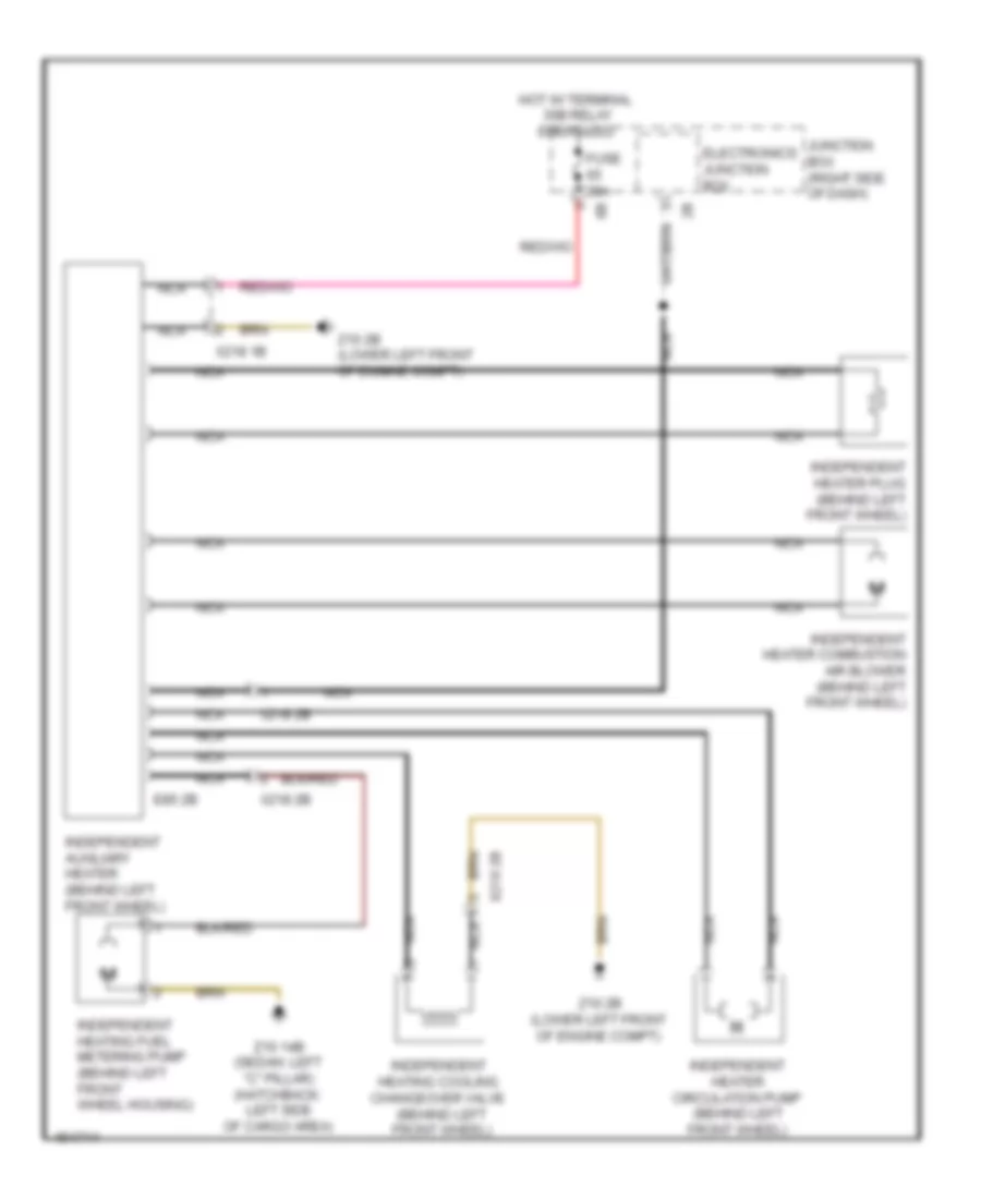
Independent Heating Wiring Diagram for BMW 535i GT 2014
List of elements for Independent Heating Wiring Diagram for BMW 535i GT 2014:
- E85 2b
- Electronics junction box
- Fuse 20a
- Hot w/ terminal 30b relay energized
- Independent auxiliary heater (behind left front wheel)
- Independent heater circulation pump (behind left front wheel)
- Independent heater combustion air blower (behind left front wheel)
- Independent heater plug (behind left front wheel)
- Independent heating cooling changeover valve (behind left front wheel)
- Independent heating fuel metering pump (behind left front wheel housing)
- Junction box (right side of dash)
- Nca
- X218 1b
- X218 2b
- Z10 14b (sedan: left "c" pillar) (hatchback: left side of cargo area)
- Z10 2b (lower left front of engine compt)
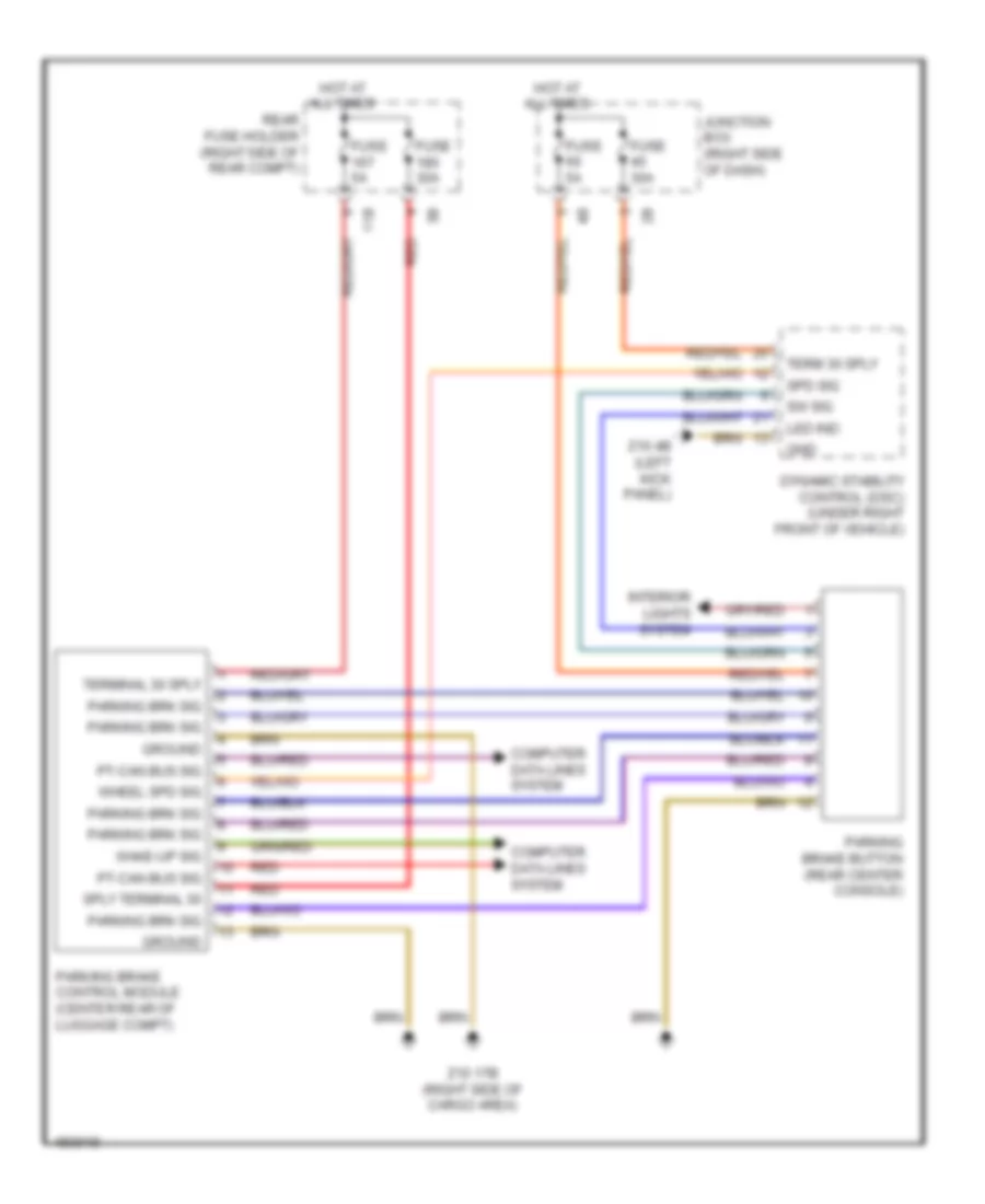
ANTI-LOCK BRAKES
Anti-lock Brakes Wiring Diagram (1 of 2) for BMW 535i GT 2014
List of elements for Anti-lock Brakes Wiring Diagram (1 of 2) for BMW 535i GT 2014:
- (behind right front wheel) right front wheel speed sensor
- (or red)
- (top of brake pedal assembly) (hybrid) brake pedal travel sensor
- 13b
- Activation, led function ind
- Brake fluid level switch (left rear engine compt)
- Computer data lines system
- Conditioned wheel spd sig
- Dynamic stability control (dsc) (under right front of vehicle)
- Except hybrid
- Flexray bus sig
- Fuse 30a
- Fuse 50a
- Fuse 5a
- Gnd
- Gnd brk pedal
- Hot at all times
- Hot w/ bi-stable relay energized
- Hybrid
- Junction box (right side of dash)
- Left rear wheel speed sensor (left rear wheel)
- Nca
- Power distribution system
- Rear fuse holder (right side of rear compt)
- Red
- Right rear brake pad wear sensor (behind right rear wheel)
- Right rear wheel speed sensor (right rear wheel)
- Sig brk pedal
- Sig, brk pad wear
- Sply brk pedal
- Sply, terminal 30
- Sply, terminal 30f
- Sw sig
- Wake-up sig, terminal 15
- Wheel spd sig
- Z10 13b (hatchback: right side of cargo area) (sedan: right "c" pillar)
- Z10 4b (left kick panel)
- Z10 9b (left kick panel)
Anti-lock Brakes Wiring Diagram (2 of 2) for BMW 535i GT 2014
List of elements for Anti-lock Brakes Wiring Diagram (2 of 2) for BMW 535i GT 2014:
- (behind left front wheel) left front brake pad wear sensor
- (center rear of luggage compt) parking brake control module
- (left front wheel) left front wheel speed sensor
- (rear center console) parking brake button
- Brake light switch (left side of dash)
- Car access system (lower left center of dash)
- Computer data lines system
- Except gt
- Footwell module (left kick panel)
- Nca
- Pnk
- Steering column switch cluster
- Z10 2b (lower left front of engine compt)
- Z10 9b (left kick panel)
ANTI-THEFT
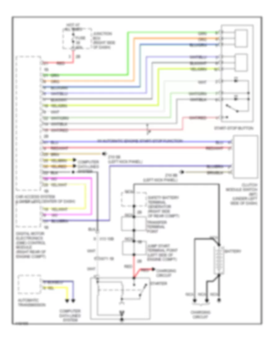
Access/Start Wiring Diagram (1 of 2) for BMW 535i GT 2014
List of elements for Access/Start Wiring Diagram (1 of 2) for BMW 535i GT 2014:
- (left kick panel) z10 9b
- (left side of dash) brake light switch
- (right side of dash) crash safety module
- 15n rly activ
- 3.0l turbo
- 4.4l turbo
- Active starter
- Aerial sig
- Bonnet contact switch
- Brk lt sw sig
- Bumper aerial
- Car access system (lower left center of dash)
- Cas bus
- Computer data lines system
- Digital motor electronics (dme) control module (right rear engine compt)
- Digital motor electronics control module 2
- Door locks system
- Eng strt sig
- Exterior lights system
- Footwell module (left kick panel)
- Front center console interior aerial (center of dash)
- Fuse 40a
- Fuse 5a
- Ground
- Hot at all times
- Hot w/ bi-stable relay energized
- Junction box (right side of dash)
- Junction box electronics
- K can 2-h
- K can 2-l
- Lin bus sig
- Luggage compartment aerial
- Luggage compartment aerial 2
- Power distribution system
- Rear center console interior aerial (rear of center console)
- Rear fuse holder (right side of rear compt)
- Red
- Sig
- Starting/charging system
- Sw sig
- Term 15 sply
- Term 15n rly
- Term 30 sply
- Term 30b
- Term 30b sply
- Terminal 15n relay
- Terminal 30b relay
- Wake up sig
- X149 1b
- Z10 2b (lower left front of engine compt)
- Z10 5b (left kick panel)
- Z10 6b (right kick panel)
- Z10 8b (right side of cargo area)
- Z10 9b (left kick panel)
Access/Start Wiring Diagram (2 of 2) for BMW 535i GT 2014
List of elements for Access/Start Wiring Diagram (2 of 2) for BMW 535i GT 2014:
- Aerial sig
- Car access system (lower left center of dash)
- Computer data lines system
- Door locks system computer data lines system
- Driver electronic outer door handle module
- Driver's side exterior aerial
- Front passenger side external aerial
- Gnd
- Ground
- Hall sens sig
- Led activation
- Passenger electronic outer door handle module
- Rear driver's side outer door handle electronic module
- Rear passenger's side outer door handle electronic module
- Red
- Ring aerial
- Sig
- Start-stop button
- Switch sig
- Term 15n rly
- Term 30b rly
- Trunk, tailgate, fuel doors system
- W/ automatic engine start stop function
- Wake up sig
- X28 1b
- X5 1b
- X8 1b
- X9 1b
- Z10 5b (left kick panel)
- Z10 6b (right kick panel)
Anti-theft & Central Locking Wiring Diagram (1 of 2) for BMW 535i GT 2014
List of elements for Anti-theft & Central Locking Wiring Diagram (1 of 2) for BMW 535i GT 2014:
- (right rear wheelwell) siren w/ tilt alarm sensor
- Aerial diversity
- Anti-theft alarm system
- Boot lid/ tailgate lock
- Car access system (lower left center of dash)
- Central locking button hazard warning switch operating facility
- Central locking drive fuel filler flap
- Computer data lines system
- Driver's door automatic soft-close drive
- Driver's door system lock (rear of driver's door)
- Electrochromic interior rearview mirror
- Electronics junction box
- Footwell module (left kick panel)
- Fuse 15a
- Fuse 20a
- High variant roof functions module
- Hot at all times
- Hotel position switch
- Interior lights system
- Interior rear lid button
- Junction box (right side of dash)
- Nca
- Noise suppression filter
- Rear lid central arrest button
- Rear lid lock 2
- X188 1b
- X28 1b
- X5 1b
- X8 1b
- X9 1b
- Z10 11b (right kick panel)
- Z10 17b (right side of cargo area)
- Z10 20b (top of right "c" pillar)
- Z10 5b (left kick panel)
Anti-theft & Central Locking Wiring Diagram (2 of 2) for BMW 535i GT 2014
List of elements for Anti-theft & Central Locking Wiring Diagram (2 of 2) for BMW 535i GT 2014:
- (left kick panel) z10 5b
- (right kick panel) z10 6b
- 11b
- Fuse 10a
- Fuse 5a
- Hot at all times
- Hot w/ terminal 30b relay energized
- Nca
- Passenger's door automatic soft-close drive
- Passenger's door system lock (rear of front passenger's door)
- Power distribution system
- Rear driver's side automatic soft-close drive
- Rear driver's side door lock
- Rear fuse holder (right side of rear compt)
- Rear passenger's side automatic soft-close drive
- Rear passenger's side door lock
- X28 1b
- X5 1b
- X8 1b
- X9 1b
- Z10 5b (left kick panel)
- Z10 6b (right kick panel)
BODY CONTROL MODULES
Body Control Modules Wiring Diagram (1 of 2) for BMW 535i GT 2014
List of elements for Body Control Modules Wiring Diagram (1 of 2) for BMW 535i GT 2014:
- Ambient lt
- Bi-xenon
- Brk lt act
- Computer data lines system
- Door locks, exterior lights & anti- theft systems
- Drv mod sply
- Exterior lights system
- Flash ind lt
- Fog lts act
- Foot lt act
- Footwell module (left kick panel)
- Fuse 40a
- Ground
- Haz sw sig
- Headlights & exterior
- Headlights & exterior lights systems
- Headlights system
- Headlights, exterior
- Hi beam hdlp act
- Hot w/ bi-stable relay energized
- Int lt act
- Interior lights system
- Junction box (right side of dash)
- K-can bus
- Led act
- Lights & interior lights systems
- Lights systems
- Lin bus sig
- Lo beam lt act
- Navigation system
- Pwr sply
- Rear fog lt
- Rev lt act
- Tail lt act
- Term 30f sply
- Turn sig/hi beam sw
- Z1 3b
- Z10 22b (left kick panel)
Body Control Modules Wiring Diagram (2 of 2) for BMW 535i GT 2014
List of elements for Body Control Modules Wiring Diagram (2 of 2) for BMW 535i GT 2014:
- (left kick panel) z10 5b
- Ambient lt
- Anti-theft system
- Brake lt act
- Brk lt act
- Brk sw sig
- Cons load sig
- Courtesy lt act
- Door locks system
- Dr contact sig
- Entrance lt act
- Exterior lights system
- Flash ind lt act
- Flash lt act
- Fog lt act
- Footwell module (left kick panel)
- Fuse 10a
- Fuse 30a
- Fuse 40a
- Ground
- Hall sens ground
- Hall sens sig
- Headlights & exterior lights systems
- Headlights system
- Hi beam lt act
- Hot w/ bi-stable relay energized
- Int lt sw sig
- Interior lights system
- Junction box (right side of dash)
- License plate lt act
- Low beam lt sig
- Memory systems
- Power windows system
- Pw drive act
- Rear fuse holder (right side of rear compt)
- Red
- Reversing lt act
- Right fog lt act
- Str clmn adj act
- Sw sig
- Tail lt act
- Term 15 sply
- Term 30f pwr sply
- Term 30f sply
- Z1 3b
- Z1 5b
- Z10 22b (left kick panel)
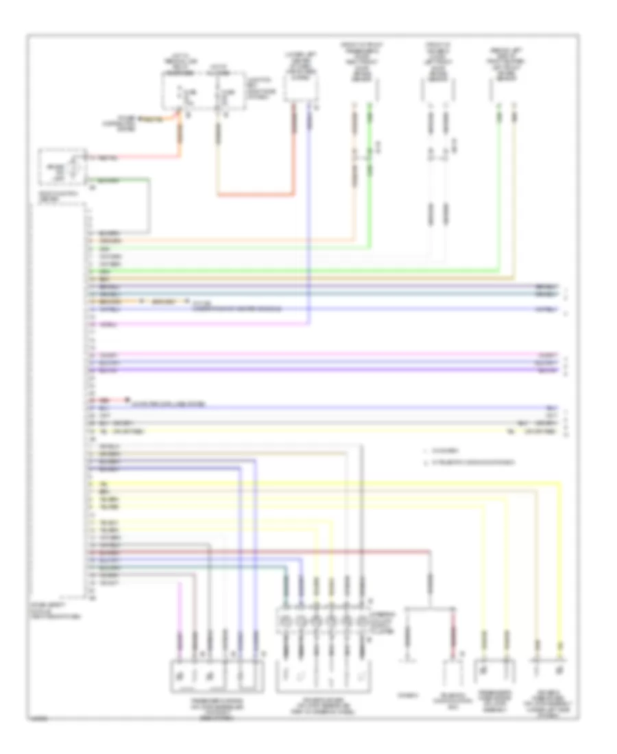
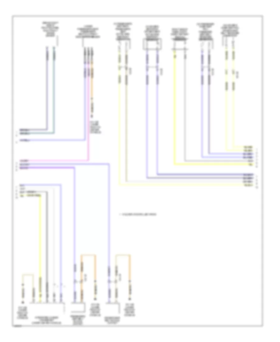
COMPUTER DATA LINES
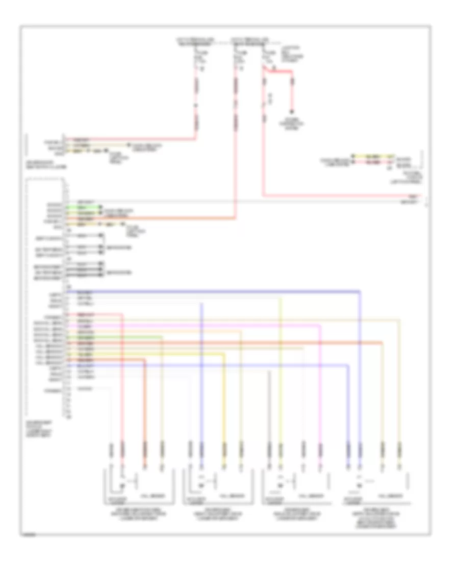
Computer Data Lines Wiring Diagram (1 of 6) for BMW 535i GT 2014
List of elements for Computer Data Lines Wiring Diagram (1 of 6) for BMW 535i GT 2014:
- (m5) digital motor electronics 2
- (right footwell, under carpet) active steering module
- (right kick panel) vertical dynamics management
- (under center of luggage compt floor) regulated differential lock
- 535xi & 535xi gt
- 550xi & 550xi gt
- All-round vision camera (left rear of luggage compt)
- Awd
- Bus sig
- Can3 h
- Can3 l
- Central gateway module (left end of dash)
- Central information display
- Diagnosis bus signal
- Ethernet data signal
- Flexray bus signal
- Ground
- Head unit
- Head-up display
- Heating/air conditioning system
- Hifi amplifier (left side of rear compt)
- K-can bus signal
- Left front damper satellite
- Left rear damper satellite
- Most bus signal
- Nca
- Pnk
- Pnk/red
- Pt-can bus signal
- Rear axle king pin inclination control actuator (on rear axle assembly)
- Red
- Right front damper satellite
- Right rear damper satellite
- Sound systems
- Terminal 15
- Terminal 30f
- Video switch
- W/ active steering
- X13 10b
- X13 2b
- Z10 22b (left kick panel)
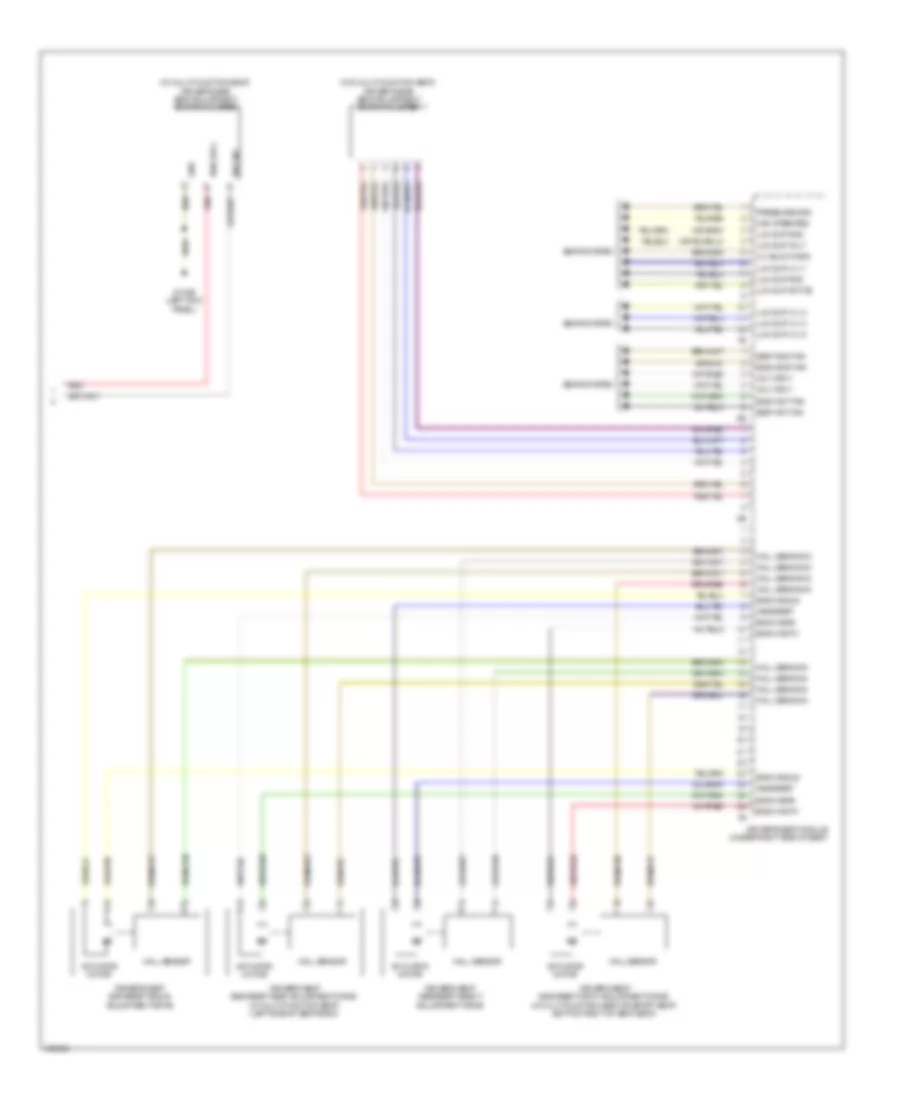
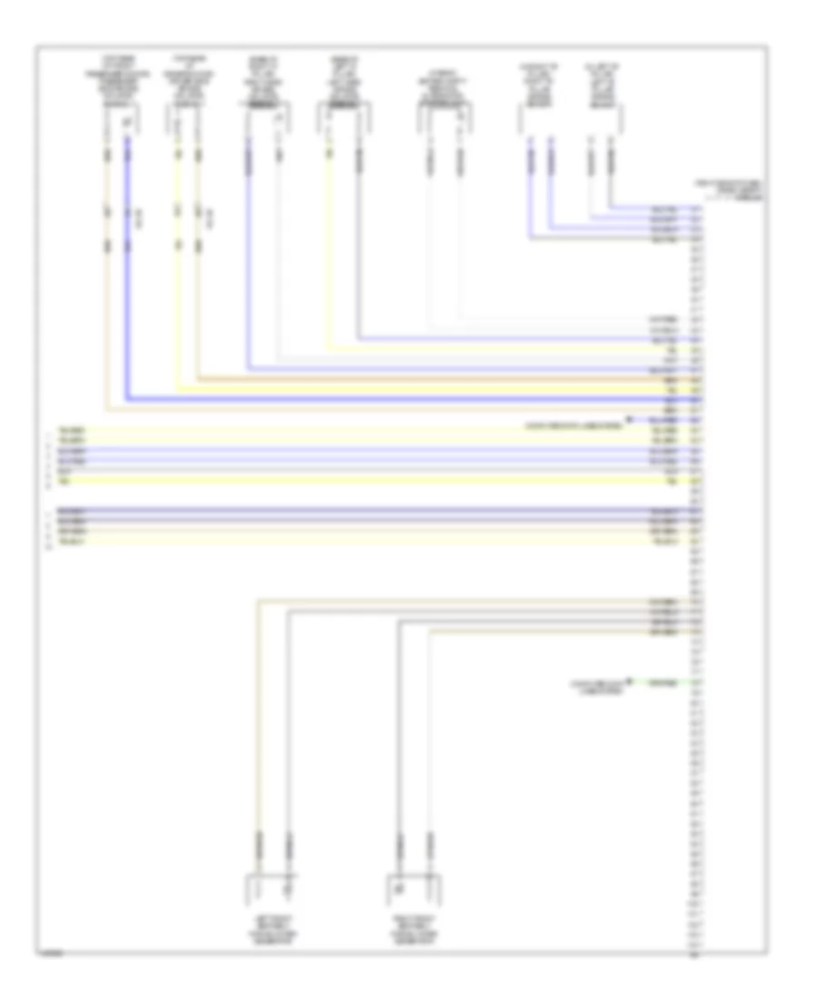
Computer Data Lines Wiring Diagram (2 of 6) for BMW 535i GT 2014
List of elements for Computer Data Lines Wiring Diagram (2 of 6) for BMW 535i GT 2014:
- (behind right side of rear bumper) lane change warning
- (bottom rear of transmission) transfer box
- (on steering rack assembly) (if equipped) electromechanical power steering
- (under right front of vehicle) dynamic stability control (dsc)
- Diagnosis socket
- Except m5
- Fuse 5a
- Hot w/ bi-stable relay energized
- Instrument cluster control unit
- Junction box (right side of dash)
- Left headlight
- Left targeted illumination
- Maneuvering assistant
- Pnk
- Pnk/red
- Red
- Right headlight
- Right targeted illumination
- Steering column switch cluster
- Vehicle sound generator (right front of engine compt)
- W/ lane change warning
- W/ parking
- W/o parking
- X148 1b
- X149 1b
- Z1 5b
- Z10 22b (left kick panel)
- Z10 5b (left kick panel)
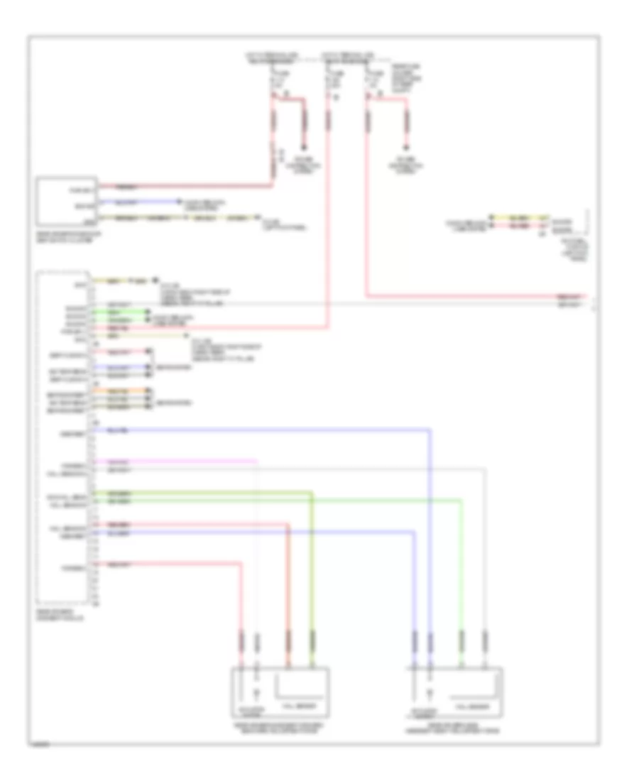
Computer Data Lines Wiring Diagram (3 of 6) for BMW 535i GT 2014
List of elements for Computer Data Lines Wiring Diagram (3 of 6) for BMW 535i GT 2014:
- Boot lid lift
- Car access system (lower left center of dash)
- Combox
- Controller
- Diagnosis socket terminating resistor
- Driver's door seat switch cluster
- Driver's door switch block
- Driver's seat module (under right side of seat)
- Electronic ride-height control
- Footwell module (left kick panel)
- Light switch unit
- Passenger's seat module (under passenger's seat)
- Pnk
- Pnk/red
- Rear compartment air conditioning system
- Rear compartment automatic climate control
- Rear compartment display
- Rear compartment display 2
- Red
- Right exterior mirror
- Telematic communication box
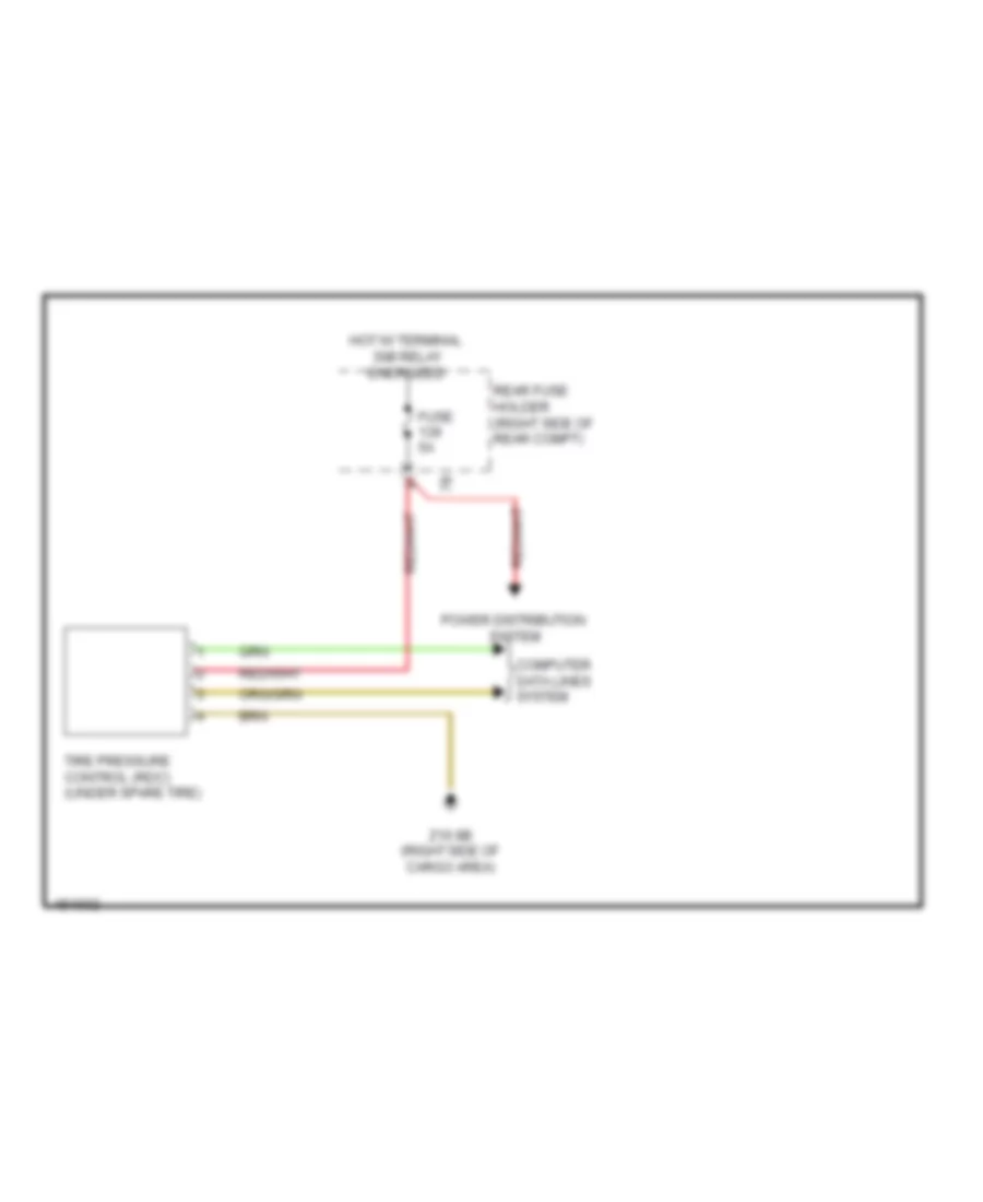
- Tire pressure control (under spare tire)
- Touchbox
- Trailer module (under spare tire)
- X12 1b
- X14 1b
- X188 1b
- X25 1b
- X28 1b
- X5 1b
Computer Data Lines Wiring Diagram (4 of 6) for BMW 535i GT 2014
List of elements for Computer Data Lines Wiring Diagram (4 of 6) for BMW 535i GT 2014:
- (rain/lights sensor: front center of roof) (solar sensor: top center of dash) rain/lights/ condensation/ solar sensor
- (right front of engine compt) (hybrid) air conditioning compressor (electrical)
- (right side of dash) junction box
- A34 1b
- A34 2b
- A34 3b
- Blower output stage (next to blower motor)
- Camera based driver assistance systems (left end of dash)
- Crash safety module (right side of dash)
- Electrochromic interior rearview mirror
- Electronics junction box
- Left front footwell flap motor (top left side of dash)
- Left reversible electromotive electrically motorized reel
- Night vision electronic module (under right side of dash)
- Pnk
- Pnk/red
- Rear compartment controller
- Rear driver's side door seat switch cluster
- Rear driver's side power window switch
- Rear driver's side seat module
- Rear passenger's side seat module
- Red
- Sedan
- W/ high variant roof function module
- Wiper module
- X01001
- X13 10b
- X167 1b
- X188 1b
- X8 1b
Computer Data Lines Wiring Diagram (5 of 6) for BMW 535i GT 2014
List of elements for Computer Data Lines Wiring Diagram (5 of 6) for BMW 535i GT 2014:
- (center rear of luggage compt) parking brake control unit
- (if equipped) high variant roof function module
- (on air recirculation control microfilter compt) automatic air recirculation control (auc) sensor
- (under center rear of luggage compt floor) scr control unit
- (under vehicle, near right front wheel) servotronic
- 4.4l except gt & 3.0l gt
- 4.4l gt & 3.0l except gt
- Driver's seat heating module
- Except gt
- Fuel pump control (ekps) (left rear of luggage compt)
- Gear selector switch
- Management electronics accumulator (hybrid)
- Parking assistant (on rear panel of spare wheel well)
- Passenger's seat heating module
- Pnk
- Pnk/red
- Rear driver's side seat heating module
- Rear driver's side seat heating switch
- Rear passenger's side seat heating module
- Rear passenger's side seat heating switch
- Red
- Regular rear axle differential lock (m5)
- W/ lane change warning
- W/o lane change warning
- W/o rear compartment automatic climate control
- W/o seat module
- X12 1b
- X14 1b
Computer Data Lines Wiring Diagram (6 of 6) for BMW 535i GT 2014
List of elements for Computer Data Lines Wiring Diagram (6 of 6) for BMW 535i GT 2014:
- (bottom rear of transmission) transfer box
- (hybrid) charging interface module
- (right front side of bumper) active cruise control
- (under center console) integrated chassis management
- 2.0l turbo
- 3.0l turbo
- 3.0l turbo diesel
- 4.4l turbo except gt
- 4.4l turbo gt & 3.0l turbo
- A/t
- Auxiliary battery charging controller (right side of luggage compt)
- Digital motor electronics (dme) control module (except 3.0l turbo diesel) digital diesel electronics (3.0l turbo diesel) (3.0l turbo, 4.4l turbo & 3.0l turbo hybrid: right rear engine compt) (2.0l turbo: top rear of engine)
- Digital motor electronics 2 (m5)
- Double clutch transmission (m5)
- Electronic machine electronics (hybrid)
- Electronic transmission control (right rear of transmission)
- Except gt 4.4l
- Except m5 4.4l turbo
- Gt 4.4l & 3.0l
- Intelligent battery sensor (below right side luggage compt)
- M5 4.4l turbo & 2.0l turbo
- Nca
- Pnk
- Pnk/red
- Pressurized full tank control module
- Radiator shutter drive unit
- Red
- Right reversible electromotive electrically motorized reel
- Starter/alternator electronics (hybrid)
- Terminating resistor
- Terminating resistor 2
- W/ twin clutch gearbox
- W/o twin clutch gearbox
- X13 10b
- X13 11b
- X13 3b
- X148 1b
- Z10 2b (lower left front of engine compt)
- Z10 6b (right kick panel)
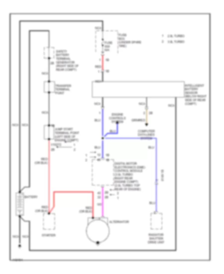
COOLING FAN
Cooling Fan Wiring Diagram for BMW 535i GT 2014
List of elements for Cooling Fan Wiring Diagram for BMW 535i GT 2014:
- (hybrid) front refrigerant shut-off valve
- (left side of engine) electric coolant pump
- (right front of battery compt) electric fan cutoff relay
- Accumulator management electronics (hybrid)
- Activation
- Auxiliary water pump (hybrid) (left front of engine compt)
- Bsd bus sig
- Characteristic map thermostat (left front of engine)
- Computer data lines system
- Coolant pmp sply
- Digital motor electronics (dme) control module (right rear engine compt)
- Ect sens gnd
- Electric fan (right front side of engine compt)
- Electric fan cutoff relay (right front of battery compt)
- Electric-machine electronics (hybrid)
- Engine coolant temperature sensor
- Fan activation
- Front power distribution box
- Fuse 100a
- Fuse 10a
- Fuse 50a
- Fuse 5a
- Fuse 60a
- Fuse 7.5a
- Fuse box (under spare tire)
- Hot at all times
- Hot w/ terminal 15n relay energized
- Hot w/ terminal 30b relay energized
- Junction box (right side of dash)
- Lin bus sig
- Nca
- Power distribution system
- Radiator shutter drive unit
- Rear fuse holder (right side of rear compt)
- Red
- Refrigerant shutoff valve (high voltage battery) (hybrid)
- Sens gnd
- Sply
- W/ fan 400/600w
- W/ fan 800/1000w
- X13 12b
- X148 1b
- X671 1b
- X705 1b
- Z10 15b (left rear of engine compt)
- Z10 2b (lower left front of engine compt)
- Z10 5b (left kick panel)
- Z6000 4b
CRUISE CONTROL
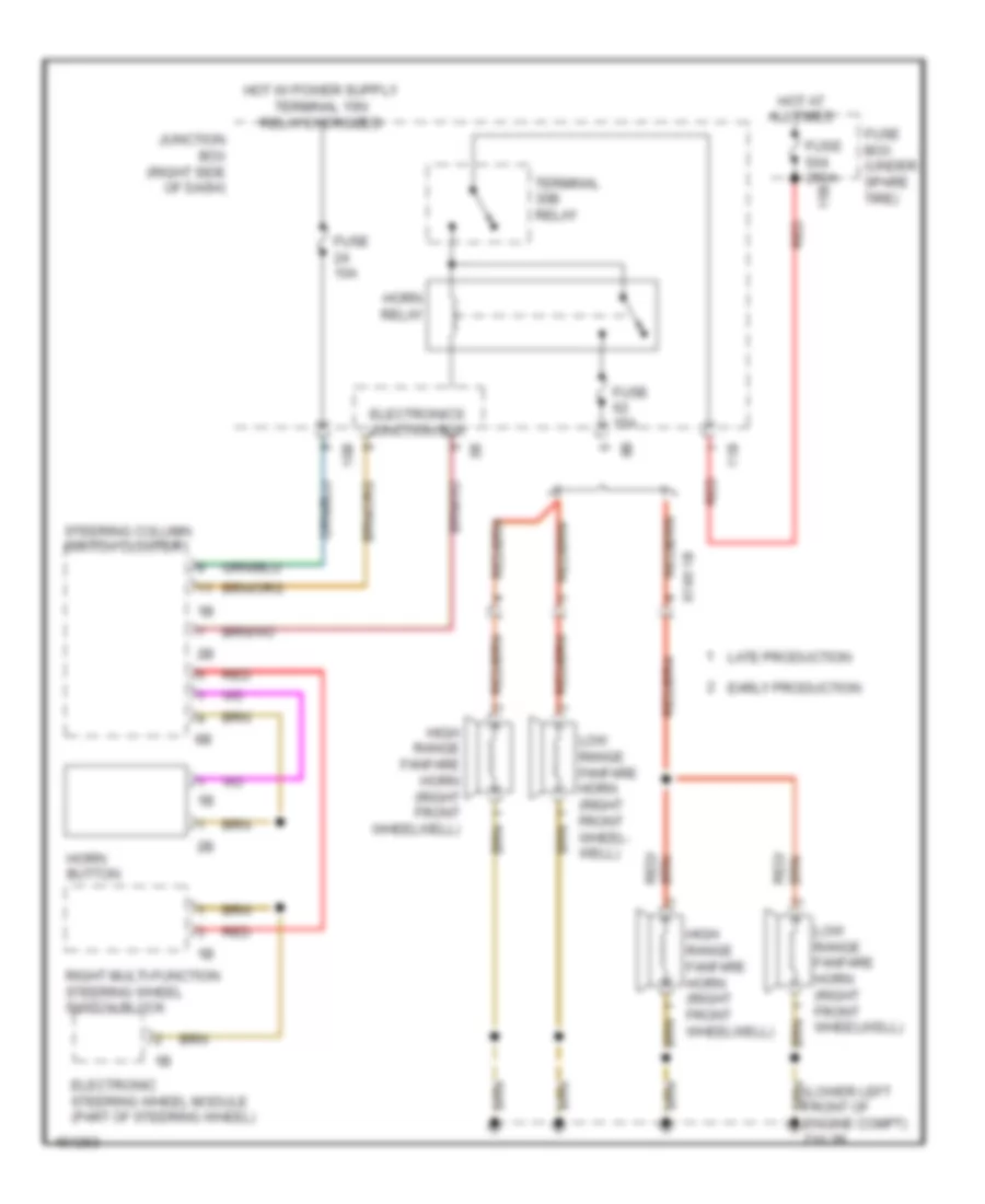
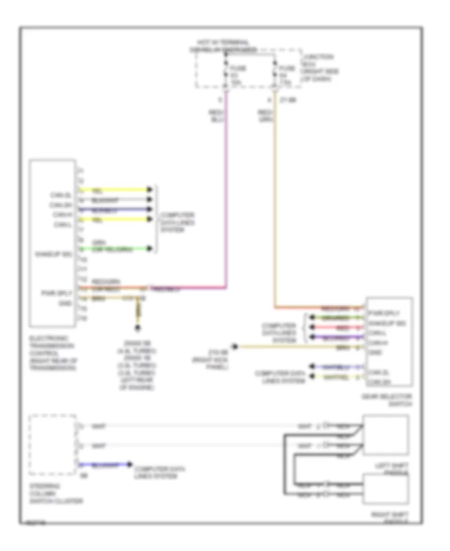
Cruise Control Wiring Diagram for BMW 535i GT 2014
List of elements for Cruise Control Wiring Diagram for BMW 535i GT 2014:
- (left side of dash) brake light switch
- 528i, 528i xdrive, m5
- 535i, 535i xdrive, 535i gt, 535i gt xdrive & active hybrid 5
- Accelerator pedal module (part of acceleration pedal assembly)
- Active cruise control (right front side of bumper)
- Active hybrid 5
- Car access system (lower left center of dash)
- Central gateway module (left end of dash)
- Clutch module (m/t) (under left side of dash)
- Computer data lines system
- Digital motor electronics (dme) control module (except 4cyl: right rear engine compt) (4 cyl: top rear of engine)
- Dynamic stability control (dsc) (under right front of vehicle)
- Electromotive throttle valve (front of engine)
- Except active hybrid 5
- Flexray bus sig
- Footwell module (left kick panel)
- Fuse 15a (0r 10a)
- Fuse 5a
- Gear selector switch
- Gnd
- Hall sensor gnd
- Hall sensor sig
- Hall sensor sply
- Hot w/ terminal 15n relay energized
- Hot w/ terminal 30b relay energized
- Integrated chassis management (under center console)
- Junction box (right side of dash)
- Pnk
- Power distribution system
- Pt-can bus sig
- Red
- S-can bus sig
- Sig
- Steering column switch cluster
- Terminal 30, sply
- Throttle vlv activ
- Throttle vlv gnd
- Throttle vlv sig
- Throttle vlv sply
- X148 1b
- Z10 2b (lower left front of engine compt)
- Z10 9b (left kick panel)
- Z6000 1b (3.0l turbo) z6000 4b (2.0l turbo) (3.0l turbo: left rear of engine)
DEFOGGERS
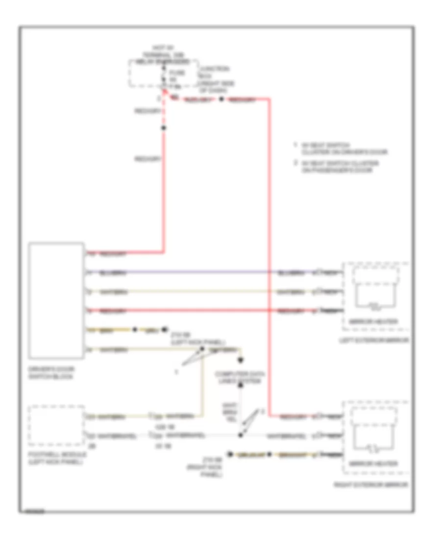
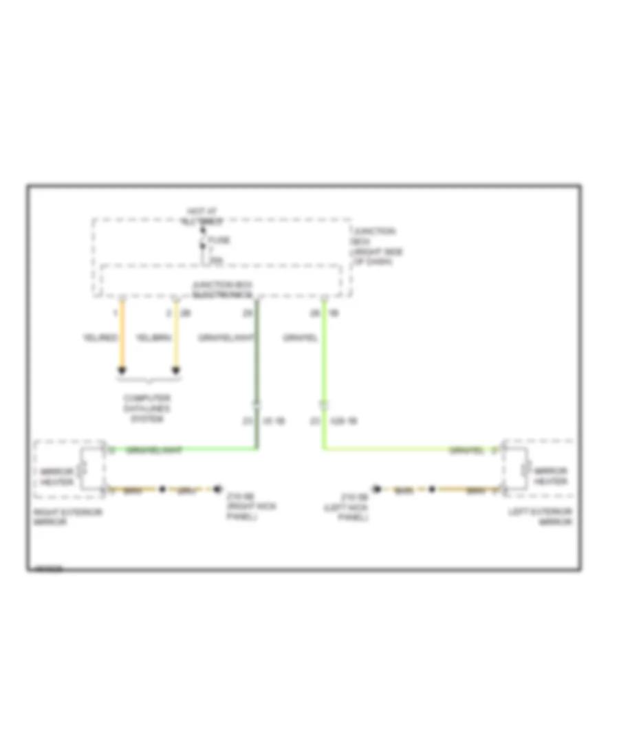
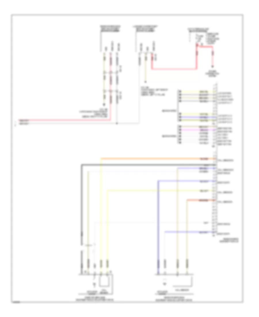
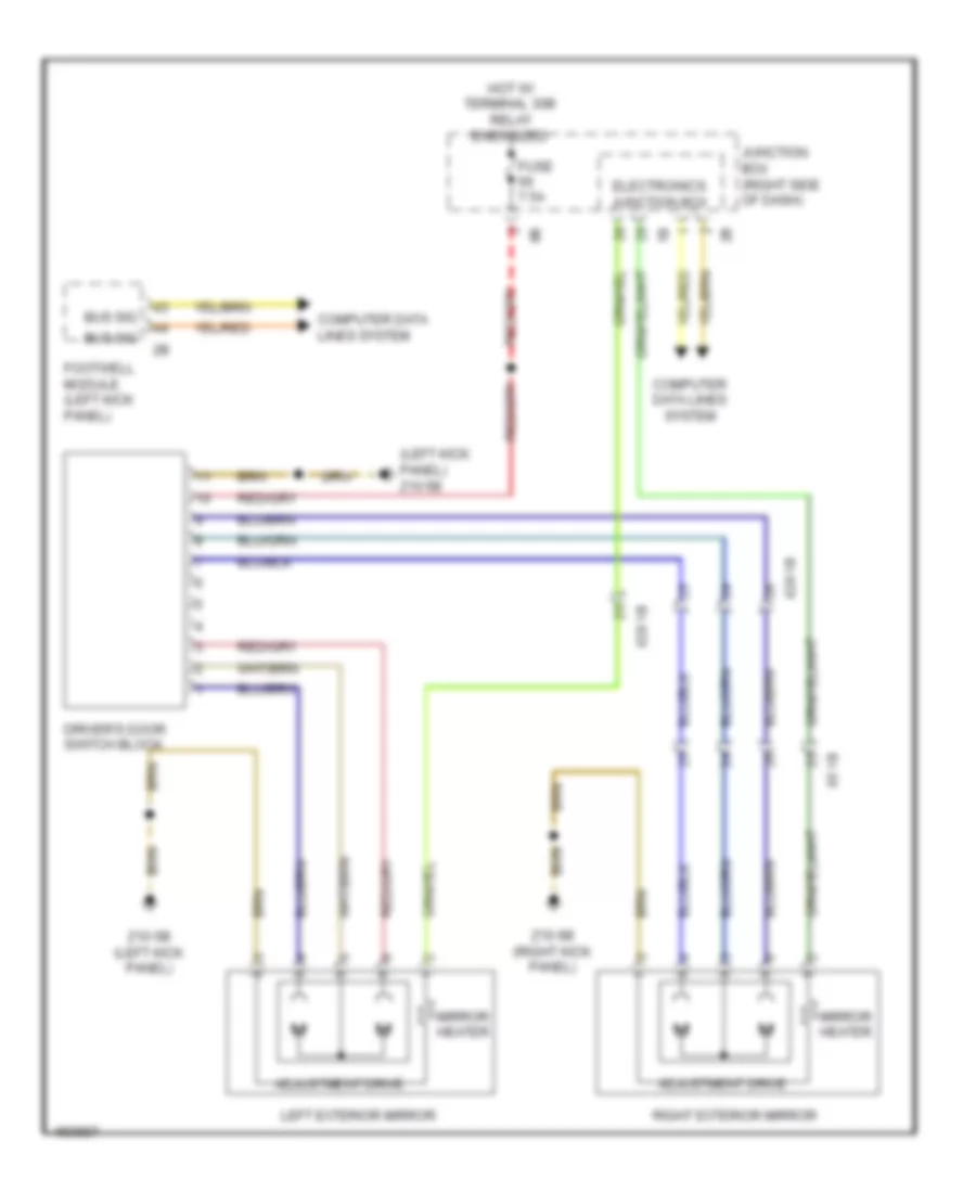
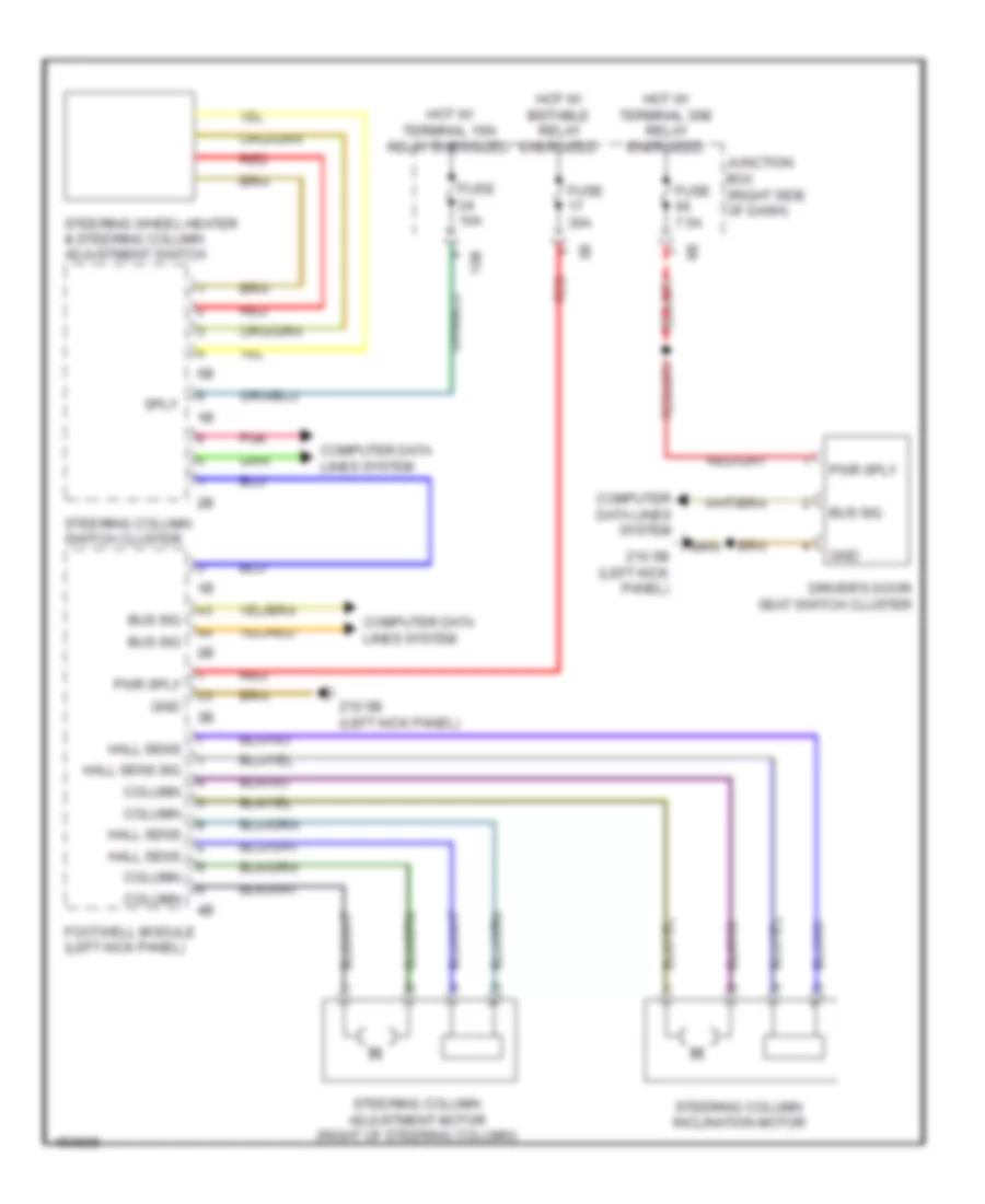
Heated Mirrors Wiring Diagram, with LIN bus Function for BMW 535i GT 2014
List of elements for Heated Mirrors Wiring Diagram, with LIN bus Function for BMW 535i GT 2014:
- Computer data lines system
- Driver's door switch block
- Footwell module (left kick panel)
- Fuse 7.5a
- Hot w/ terminal 30b relay energized
- Junction box (right side of dash)
- Left exterior mirror
- Mirror heater
- Nca
- Right exterior mirror
- W/ seat switch cluster on driver's door
- W/ seat switch cluster on passenger's door
- X28 1b
- X5 1b
- Z10 5b (left kick panel)
- Z10 6b (right kick panel)
Heated Mirrors Wiring Diagram, without LIN bus Function for BMW 535i GT 2014
List of elements for Heated Mirrors Wiring Diagram, without LIN bus Function for BMW 535i GT 2014:
- Computer data lines system
- Fuse 30a
- Hot at all times
- Junction box (right side of dash)
- Junction box electronics
- Left exterior mirror
- Mirror heater
- Right exterior mirror
- X28 1b
- X5 1b
- Z10 5b (left kick panel)
- Z10 6b (right kick panel)
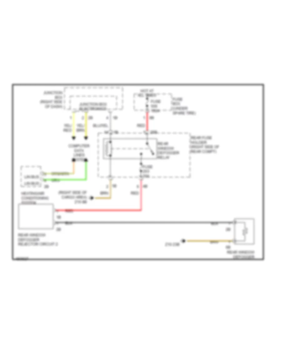
Rear Defogger Wiring Diagram for BMW 535i GT 2014
List of elements for Rear Defogger Wiring Diagram for BMW 535i GT 2014:
- (right side of cargo area) z10 8b
- 25b
- Computer data lines system
- Fuse 150a
- Fuse 30a
- Fuse box (under spare tire)
- Heating/air conditioning system
- Hot at all times
- Junction box (right side of dash)
- Junction box electronics
- Lin bus
- Rear fuse holder (right side of rear compt)
- Rear window defogger
- Rear window defogger rejector circuit 2
- Rear window defogger relay
- Red
- Z10 23b
ELECTRONIC POWER STEERING
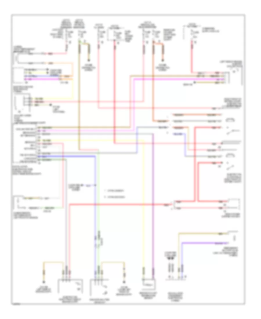
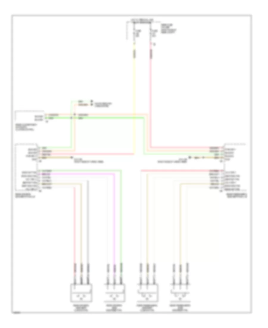
Active Power Steering Wiring Diagram for BMW 535i GT 2014
List of elements for Active Power Steering Wiring Diagram for BMW 535i GT 2014:
- (left kick panel) z10 5b
- Activation servomotor
- Active steering module (right footwell, under carpet)
- Active steering servo motor
- Central gateway module (left end of dash)
- Electric servo motor lock
- Flexray bus sig
- Fuse 40a
- Fuse 5a
- Gnd
- Hot at all times
- Hot w/ terminal 15n relay energized
- Junction box (right side of dash)
- Lock out
- Nca
- Pnk/red
- Rear axle king pin inclination control (on rear axle assembly)
- Servomotor sig
- Servomotor sig activation servomotor lock out
- Servomotor sply
- Terminal 15 sply
- Terminal 30 sply
- X87 1b
- Z10 50b
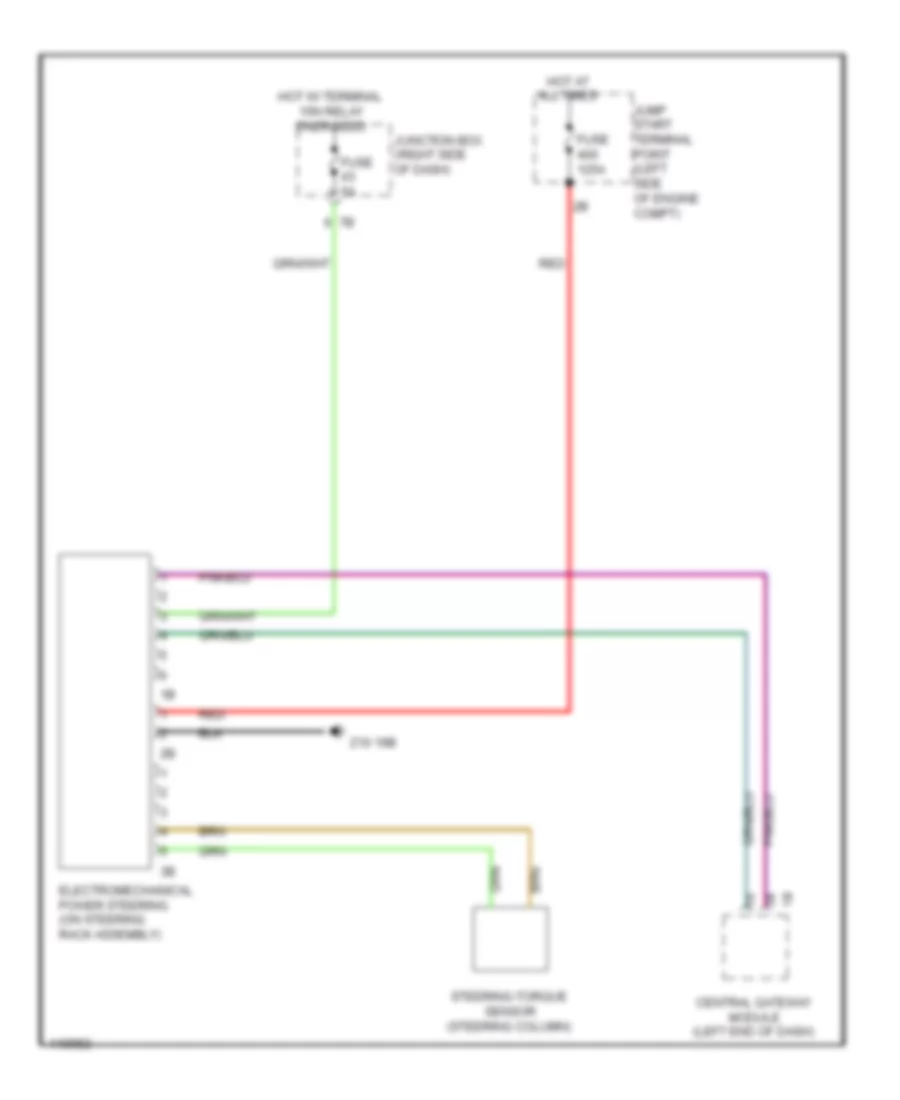
Electromechanical Power Steering Wiring Diagram for BMW 535i GT 2014
List of elements for Electromechanical Power Steering Wiring Diagram for BMW 535i GT 2014:
- Central gateway module (left end of dash)
- Electromechanical power steering (on steering rack assembly)
- Fuse 125a
- Fuse 5a
- Hot at all times
- Hot w/ terminal 15n relay energized
- Jump start terminal point (left side of engine compt)
- Junction box (right side of dash)
- Red
- Steering-torque sensor (steering column)
- Z10 19b
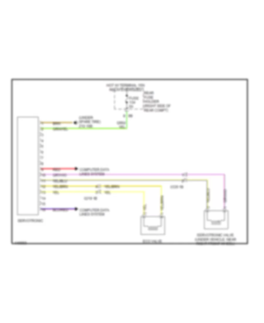
Servotronic Wiring Diagram for BMW 535i GT 2014
List of elements for Servotronic Wiring Diagram for BMW 535i GT 2014:
- (under spare tire) z10 16b
- Computer data lines system
- Eco valve
- Fuse 5a
- Hot w/ terminal 15n relay energized
- Rear fuse holder (right side of rear compt)
- Red
- Servotronic
- Servotronic valve (under vehicle, near right front wheel)
- X219 1b
- X335 1b
ELECTRONIC SUSPENSION
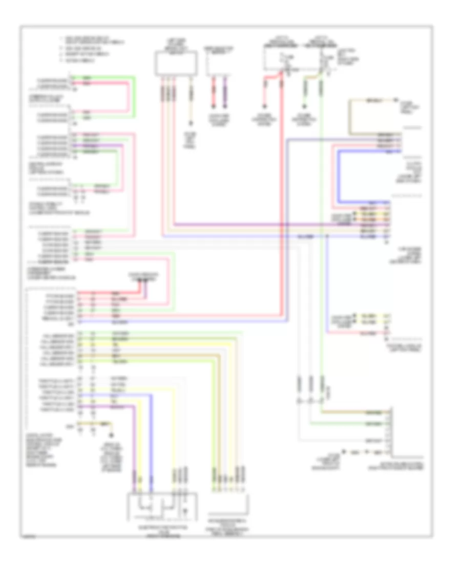
Air Suspension Wiring Diagram (1 of 2) for BMW 535i GT 2014
List of elements for Air Suspension Wiring Diagram (1 of 2) for BMW 535i GT 2014:
- (behind right front wheel) (w/ vertical dynamics management) right front level sensor
- (left end of dash) central gateway module
- (right kick panel) z10 11b
- (under front of center console) z10 10b
- 2.0l turbo & 4.4l turbo m5
- 3.0l turbo & 3.0l turbo hybrid
- 3.0l turbo diesel & 4.4 turbo except m5
- Center console operating unit
- Computer data lines system
- Digital motor electronics (dme) control module (except 3.0l turbo diesel) digital diesel electronics (3.0l turbo diesel) (2.0l turbo: top rear of engine) (4.4l turbo: right rear engine compt)
- Except m5
- Fuse 5a
- Hot w/ terminal 30b relay energized
- Integrated chassis management (under center console)
- Junction box (right side of dash)
- Left front level sensor (w/ vertical dynamics management & xenon light)
- Pnk
- Steering column switch cluster
Air Suspension Wiring Diagram (2 of 2) for BMW 535i GT 2014
List of elements for Air Suspension Wiring Diagram (2 of 2) for BMW 535i GT 2014:
- Compressor relay
- Computer data lines system
- Electronic ride height control (gt)
- Fuse 40a
- Fuse 5a
- Hot at all times
- Hot w/ terminal 30b relay energized
- Left rear level sensor (w/ vertical dynamics management, xenon light & electronic ride height control) (front of left rear wheel)
- M6 1b
- M6 2b
- Nca
- Rear fuse holder (right side of rear compt)
- Right rear level sensor (w/ vertical dynamics management & electronic ride height control) (front of right rear wheel)
- Y25 1b
- Z10 17b (right side of cargo area)
- Z10 8b (right side of cargo area)
Dynamic Drive Suspension Wiring Diagram for BMW 535i GT 2014
List of elements for Dynamic Drive Suspension Wiring Diagram for BMW 535i GT 2014:
- (right kick panel) z10 6b
- 5v sply
- Act intake throttle valve
- Act valve block
- Central gateway module (left end of dash)
- Dynamic drive valve block (behind right front wheel)
- Flexray bus sig
- Fuse 30a
- Fuse 5a
- Gnd
- Hot at all times
- Hot w/ terminal 15n relay energized
- Intake throttle valve
- Junction box (right side of dash)
- Left front damper satellite
- Left rear damper satellite
- Nca
- Oil level sw sig
- Oil level switch (right side of engine compt)
- Pnk
- Pnk/red
- Power distribution system
- Pressure sens sig
- Right front damper satellite
- Right rear damper satellite
- Sens gnd
- Sply terminal 15
- Sply terminal 30
- Vertical dynamics management (right kick panel)
- Volt sply
- X158 1b
- X159 1b
- X219 1b
- Z10 14b (hatch back: left side of cargo area) (sedan: left "c" pillar)
- Z10 2b (lower left front of engine compt)
- Z10 3b (lower right front of engine compt)
- Z10 8b (right side of cargo area)
ENGINE PERFORMANCE
3.0L TURBO
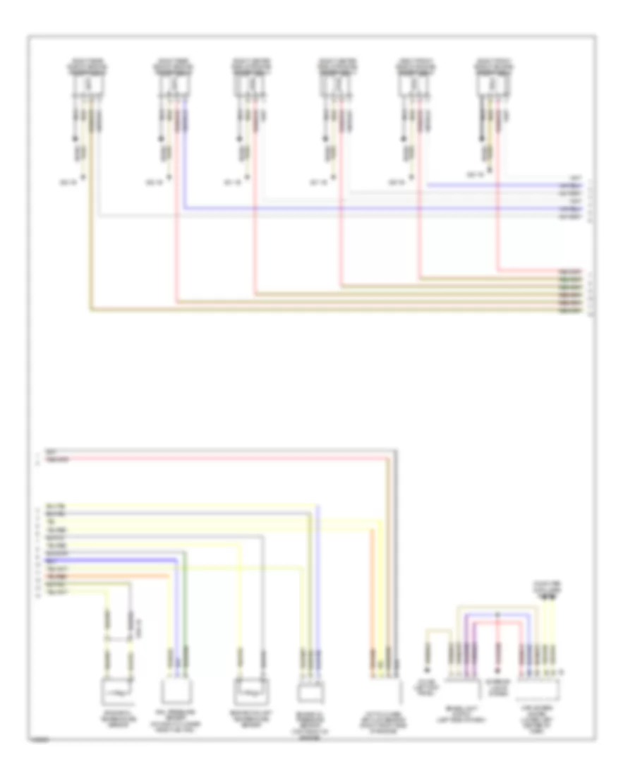
3.0L Turbo, Engine Performance Wiring Diagram (1 of 5) for BMW 535i GT 2014
List of elements for 3.0L Turbo, Engine Performance Wiring Diagram (1 of 5) for BMW 535i GT 2014:
- (right side of engine) knock sensor
- (top right rear of engine) wastegate valve pressure converter
- Act activation
- Bsd bus sig
- Bsd sig
- Coolant pump
- Cooling fans system
- Crankshaft position sensor (left rear side of engine)
- Cylinders 1-3
- Cylinders 4-6
- Digital motor electronics (dme) control module (right rear engine compt)
- Elec throttle act gnd
- Elec throttle act sig
- Electromotive throttle actuator
- Intake air temperature pressure sensor (right side of engine)
- Intake manifold pressure sensor (right side of engine)
- Knock sens sig
- Nca
- Oil level sensor
- Oxygen sensor before catalytic converter
- Quantity control valve
- Sens gnd
- Sens sig
- Sens sply
- Sply
- Starting/charging system
- Vlv activation
- Vlv sply
- X671 2b
- Zero gear sensor (m/t)
3.0L Turbo, Engine Performance Wiring Diagram (2 of 5) for BMW 535i GT 2014
List of elements for 3.0L Turbo, Engine Performance Wiring Diagram (2 of 5) for BMW 535i GT 2014:
- (top of engine) low pressure fuel sensor
- Blow off bypass valve
- Characteristic map thermostat (left front of engine)
- Computer data lines system
- Electric fuel pump (on fuel tank)
- Engine ventilation heating
- Exhaust camshaft sensor (rear of engine)
- Exhaust vanos solenoid valve (front of engine)
- Fuel pump
- Fuel pump control (ekps)
- Fuse 20a
- Fuse 5a
- Gnd
- High pressure pump position sensor
- Hot w/ terminal 30b relay energized
- Intake camshaft sensor (rear of engine)
- Intake vanos solenoid valve (front of engine)
- Junction box (right side of dash)
- Nca
- Oil pressure control valve
- Oxygen sensor after catalytic converter
- Power distribution system
- Pt can
- Pwr sply
- Rear fuse holder (right side of rear compt)
- Red
- Standard euro 6
- Tank ventilation shut-off valve (w/o bosch)
- Tank ventilation valve (w/o bosch)
- W/ bosch
- W/ exhaust emissions
- W/o bosch
- W/o exhaust emissions standard euro 6
- Wake up
- X13 1b
- X664 1b
- X705 1b
- Z1 6b
- Z10 16b (sedan) z10 18b (gran turismos) (sedan: under spare tire)
- Z23 1b
3.0L Turbo, Engine Performance Wiring Diagram (3 of 5) for BMW 535i GT 2014
List of elements for 3.0L Turbo, Engine Performance Wiring Diagram (3 of 5) for BMW 535i GT 2014:
- (left rear of engine) z6000 1b
- (right rear engine compt) digital motor electronics (dme) control module
- Activation
- Car access system (lower left center of dash)
- Diverter vlv sply
- Dme main relay
- Fuse 100a
- Fuse 15a
- Fuse 20a
- Fuse 40a
- Fuse box (under spare tire)
- Gnd
- Heater sply
- Hot at all times
- Ignition & fuel injection relay
- Map activation
- Map sply
- Meter gnd
- Meter sig
- Meter sply
- Motor position sensor
- Mtr activation
- Oil press ctrl vlv sply
- Pwr
- Red
- Sens gnd
- Sens sig
- Sens sig digital motor electronics (dme) control module (right rear engine compt)
- Sens sply
- Servomotor valvetronic
- Tank vent valve (w/ bosch)
- Valvetronic relay
- Ventilation activation
- Venturi nozzle pressure sensor (w/ bosch)
- Vlv activation
- Vlv sply
- W/ bosch
- W/o bosch
- Z10 3b (lower right front of engine compt)
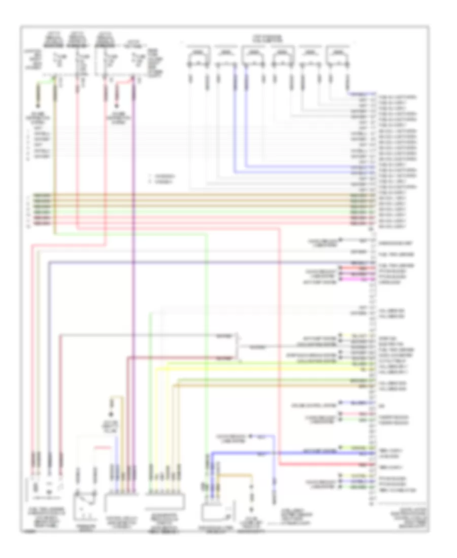
3.0L Turbo, Engine Performance Wiring Diagram (4 of 5) for BMW 535i GT 2014
List of elements for 3.0L Turbo, Engine Performance Wiring Diagram (4 of 5) for BMW 535i GT 2014:
- (right center side of engine) ignition coil 3
- (right center side of engine) ignition coil 4
- (right front side of engine) ignition coil 1
- (right front side of engine) ignition coil 2
- (right rear side of engine) ignition coil 5
- (right rear side of engine) ignition coil 6
- Brake light switch (left side of dash)
- Car access system (lower left center of dash)
- Computer data lines system
- Engine coolant temperature sensor
- Engine oil pressure sensor (top front of engine)
- Engine oil temperature sensor
- Exterior lights system
- Hot film mass air flow sensor (right front side of engine)
- Nca
- Plug spark
- Rail pressure sensor (on right cylinder head fuel rail)
- Spark plug
- X704 1b
- Z10 9b (left kick panel)
- Z20 1b
- Z21 1b
- Z22 1b
3.0L Turbo, Engine Performance Wiring Diagram (5 of 5) for BMW 535i GT 2014
List of elements for 3.0L Turbo, Engine Performance Wiring Diagram (5 of 5) for BMW 535i GT 2014:
- (top of engine) fuel injectors
- 11b
- Accelerator pedal module (part of acceleration pedal assembly)
- Anti-theft system
- Car bus sig
- Computer data lines system
- Cooling fans system
- Cruise control system
- Cut-out relay
- Dc/dc converter
- Diagnosis socket
- Digital motor electronics (dme) control module (right rear engine compt)
- Electric fan
- Flexray bus sig
- Fuel inj 1 activation
- Fuel inj 1 sply
- Fuel inj 2 activation
- Fuel inj 2 sply
- Fuel inj 3 activation
- Fuel inj 3 sply
- Fuel inj 4 activation
- Fuel inj 4 sply
- Fuel inj 5 activation
- Fuel inj 5 sply
- Fuel inj 6 activation
- Fuel inj 6 sply
- Fuel tank leakage
- Fuel tank leakage diagnostic module (w/o bosch) (behind right rear wheel)
- Fuse 10a (or 15a)
- Fuse 5a
- Hall sens gnd
- Hall sens sig
- Hall sens sply
- Hot at all times
- Hot w/ terminal 15n relay energized
- Hot w/ terminal 30b relay energized
- Ign coil 1 activation
- Ign coil 1 sply
- Ign coil 2 activation
- Ign coil 2 sply
- Ign coil 3 activation
- Ign coil 3 sply
- Ign coil 4 activation
- Ign coil 4 sply
- Ign coil 5 activation
- Ign coil 5 sply
- Ign coil 6 activation
- Ign coil 6 sply
- Intelligent battery sensor (right side of rear compt)
- Junction box (right side of dash)
- Lin bus sig
- Natural vacuum leak detection (w/ bosch)
- Nca
- Pnk
- Power distribution system
- Pressure switch
- Pt-can bus sig
- Radiator shutter drive unit
- Rear fuse holder (right side of rear compt)
- Red
- Sig
- Start sig
- Starting/charging system
- Term 15 sply
- Term 15 wake up sig
- Term 30 sply
- W/ bosch
- W/o bosch
- X148 1b
- Z1 6b
- Z1 7b
- Z10 13b (right "c" pillar)
- Z10 2b (lower left front of engine compt)
EXTERIOR LIGHTS
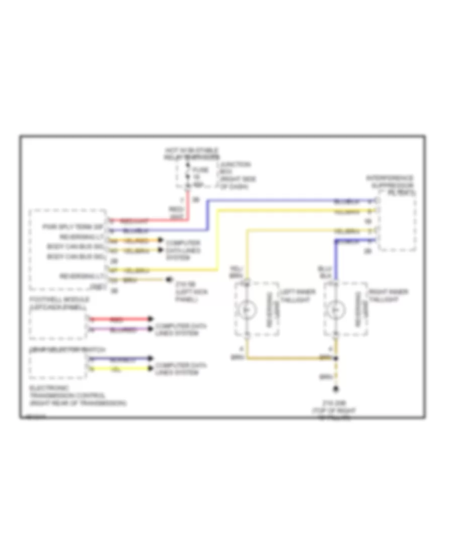
Backup Lamps Wiring Diagram for BMW 535i GT 2014
List of elements for Backup Lamps Wiring Diagram for BMW 535i GT 2014:
- Body can bus sig
- Computer data lines system
- Electronic transmission control (right rear of transmission)
- Footwell module (left kick panel)
- Fuse 40a
- Gear selector switch
- Gnd
- Hot w/ bi-stable relay energized
- Interference suppressor filter 2
- Junction box (right side of dash)
- Left inner taillight
- Light reversing
- Pwr sply term 30f
- Red
- Reversing lt
- Right inner taillight
- Z10 20b (top of right "c" pillar)
- Z10 5b (left kick panel)
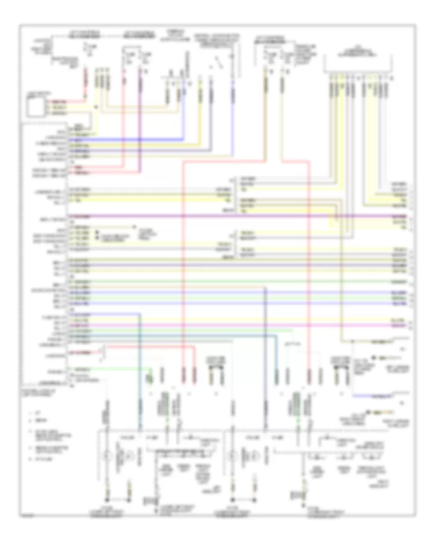
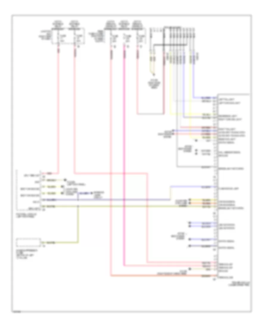
Exterior Lamps Wiring Diagram (1 of 2) for BMW 535i GT 2014
List of elements for Exterior Lamps Wiring Diagram (1 of 2) for BMW 535i GT 2014:
- (gt) interference suppressor filter 2
- (lower left front of engine compt) z10 2b
- (w/o led) cornering light
- Body can bus sig
- Brk lt
- Brk lt sw sig
- Central locking button hazard warning switch operating facility
- Computer data lines system
- Cornering lt
- Design light
- Direction
- Direction light
- Door contact sig
- Electronics junction box
- Flash ind lp
- Footwell module (left kick panel)
- Fuse 10a
- Fuse 30a
- Fuse 5a
- Gnd
- Gt w/ led
- Gt w/o led & sedan w/o adaptive light control
- Headlight driver module
- Hi beam redund
- Hi beam sw sig
- Hot w/ bi-stable relay energized
- Hot w/ bistable relay energized
- Ind lp
- Junction box (right side of dash)
- Led activation
- Left headlight
- Left license plate light
- License plate lt
- Light cornering
- Light switch unit
- Lin bus
- Lin bus sig
- Parking light/ daytime driving light
- Pwr sply
- Pwr sply term 30f
- Rear fuse holder (right side of rear compt)
- Red
- Right headlight
- Right license plate light
- Rr fog lt
- Sedan
- Sedan w/ adaptive light control
- Side marker light
- Steering column switch cluster
- Tail lt
- W/ led
- W/o led
- Warn lt sw sig
- Z10 17b (right side of cargo area)
- Z10 22b (left kick panel)
- Z10 2b (lower left front of engine compt)
- Z10 3b (lower right front of engine compt)
Exterior Lamps Wiring Diagram (2 of 2) for BMW 535i GT 2014
List of elements for Exterior Lamps Wiring Diagram (2 of 2) for BMW 535i GT 2014:
- (left side of dash) brake light switch
- (lower left center of dash) car access system
- (sedan: bottom of left "c" pillar) noise suppression filter
- Auxiliary brake light
- Brake dynamic
- Brake light
- Brk lt
- Can bus sig
- Cargo area)
- Computer data lines system
- Direction ind
- Except m5
- Flashing ind lp
- Left front direction indicator light repeater
- Left inner taillight
- Left outer taillight
- License plate light w/ rear lid button
- Light
- Light brake dynamic
- Light tail
- Power tailgate acoustic sensor
- Right front direction indicator light repeater
- Right inner taillight
- Right outer taillight
- Sedan
- Side marker light
- Tail light
- Trailer module (under spare tire)
- Z10 14b (sedan: left "c" pillar)
- Z10 17b (right side of
- Z10 17b (right side of cargo area)
- Z10 20b (top of right "c" pillar)
- Z10 2b (lower left front of engine compt)
- Z10 6b (right kick panel)
- Z10 8b (right side of cargo area)
- Z10 9b (left kick panel)
Trailer Tow Wiring Diagram for BMW 535i GT 2014
List of elements for Trailer Tow Wiring Diagram for BMW 535i GT 2014:
- Active bodyworks system
- Automatic towing hitch
- Body can bus sig
- Brake light activation
- Brk light
- Can bus signal
- Computer data lines system
- Exterior lamps circuit
- Flashing ind lamp
- Footwell module (left kick panel)
- Fuse 20a
- Fuse 30a
- Gnd
- Ground
- Hall sensor signal
- Hot w/ bi-stable relay energized
- Hot w/ terminal 30b relay energized
- Ind lp
- Junction box (right side of dash)
- Led activation
- Left taillight
- Left turn sig light
- Nca
- Noise suppressor filter (bottom of left "c" pillar)
- Rear fog light
- Rear fuse holder (right side of rear compt)
- Red
- Reversing light
- Right taillight
- Right turn sig light
- Sply term 30f
- Switch signal
- Terminal 30b
- Terminal 30f
- Trailer module (under spare tire)
- Trailer socket
- X268 1b
- X269 1b
- Z10 22b (left kick panel)
- Z10 8b (right side of cargo area)
GROUND DISTRIBUTION
Ground Distribution Wiring Diagram (1 of 6) for BMW 535i GT 2014
List of elements for Ground Distribution Wiring Diagram (1 of 6) for BMW 535i GT 2014:
- (2.0l turbo) ignition coil cylinder 1
- (2.0l turbo) ignition coil cylinder 2
- (3.0l turbo & hybrid) digital motor electronics
- (3.0l turbo diesel) a/c compressor
- (3.0l turbo diesel, 2.0l turbo & 3.0l turbo) intelligent battery sensor
- (3.0l turbo)
- (3.0l turbo) reverse gear switch
- (3.0l turbo) transfer box
- (4.4l turbo sedan) digital motor electronics 2
- (4.4l turbo) ignition coil cylinder 1
- (except hybrid) automatic transmission
- (except hybrid) electronic transmission control
- (hybrid) auxiliary water pump
- (hybrid) electric vacuum pump
- (hybrid) intelligent battery sensor
- (hybrid) intelligent battery sensor 2
- (hybrid) polarity protection reverse
- (if equipped) driver's lumbar support switch
- (if equipped) driver's seat lumbar support drive
- (if equipped) engine ventilation heating
- (m/t) reverse gear switch
- (w/ electrically operated roller sun blinds) driver's side rear power window switch
- (w/o electrically operated roller sun blinds) driver's side rear power window switch
- Active steering module
- Auxiliary battery
- Battery
- Capacitor box
- Car access system
- Diagnosis socket
- Driver electronic outer door handle module
- Driver's door automatic soft close drive
- Driver's door entrance light
- Driver's door inner door handle lighting
- Driver's door panel lighting
- Driver's door pocket lighting
- Driver's door seat switch cluster
- Driver's door switch block
- Driver's door system lock
- Driver's seat heating module
- Driver's seat module
- Driver's side rear automatic soft close drive
- Driver's side rear courtesy lighting
- Driver's side rear door lock
- Driver's side rear door panel lighting
- Driver's side rear door pocket lighting
- Driver's side rear door seat switch cluster
- Driver's side rear entry light
- Driver's side rear outer door handle electronic module
- Driver's side seat adjustment switch cluster
- E37 1b
- E82 1b
- Footwell module
- Ignition coil cylinder 1
- Ignition coil cylinder 2
- Ignition coil cylinder 3
- Ignition coil cylinder 4
- Ignition coil cylinder 5
- Ignition coil cylinder 6
- Intelligent battery sensor 2
- Interior rear lid button
- Left backrest lighting
- Left exterior mirror
- Left front entrance light
- Left front midrange speaker lighting
- Left front tweeter lighting
- Left rear electric auxiliary heater
- Left rear entrance light
- Left rear speaker lighting
- Left reversible electromotive electrically motorized reel
- Nca
- Rear driver's side inner door handle lighting
- W/ lumbar support
- X14 1b
- X28 1b
- X8 1b
- Y21 1b
- Z10 28b
- Z10 5b (left kick panel)
- Z20 1b
- Z21 1b
- Z22 1b
- Z23 1b (3.0l turbo)
- Z6000 1b (left rear of engine)
- Z6000 6b
Ground Distribution Wiring Diagram (2 of 6) for BMW 535i GT 2014
List of elements for Ground Distribution Wiring Diagram (2 of 6) for BMW 535i GT 2014:
- (4.4l
- (except m5) rear axle king pin inclination control
- (hybrid) automatic transmission
- (m5) regulated rear axle differential lock
- (right side of dash) junction box
- (sedan) fuel pump control (ekps)
- (w/ electrically operated roller sun blinds) passenger's side rear power window switch
- (w/ multi- function seat) passenger's side seat adjustment switch cluster
- (w/o electrically operated roller sun blinds) passenger's side rear power window switch
- (w/o multi- function seat) passenger's lumbar support switch
- (w/o multi- function seat) passenger's seat lumbar support drive
- 12v connection
- 12v connection 1
- A34 1b
- Ashtray lighting
- Basic
- Blower output stage
- E21 1b
- E80 1b
- Electro- mechanical power steering
- Electronics junction box
- Except m5
- Front center armrest light
- Front cigarette lighter 12v connection
- Front passenger door lock
- Gear selector switch
- Headlight washer pump
- High
- Left side center console panel lighting
- N2 1b
- Nca
- Passenger electronic outer door handle module
- Passenger's door automatic soft close drive
- Passenger's door automatic soft-close drive
- Passenger's door entrance light
- Passenger's door inner door handle lighting
- Passenger's door pocket lighting
- Passenger's door power window switch
- Passenger's door seat switch cluster
- Passenger's door system lock
- Passenger's door trim panel lighting
- Passenger's seat heating module
- Passenger's seat module
- Passenger's side rear automatic soft close drive
- Passenger's side rear courtesy lighting
- Passenger's side rear door panel lighting
- Passenger's side rear door pocket lighting
- Passenger's side rear door seat switch cluster
- Passenger's side rear entry light
- Passenger's side rear outer door handle electronic module
- Passenger's side seat adjustment switch cluster
- Rear cigarette lighter 12v connection
- Rear compartment fan motor output stage
- Rear passenger's side door lock
- Rear passenger's side inner door handling lighting
- Rear passenger's side power window switch
- Rear passenger's side system lock
- Rear window washer pump
- Right backrest lighting
- Right exterior mirror
- Right front direction indicator light repeater
- Right front entrance light
- Right front mid-range speaker lighting
- Right front tweeter lighting
- Right rear electric auxiliary heater
- Right rear entrance light
- Right rear speaker lighting
- Right reversible electromotive electrically motorized reel
- Right side center console panel lighting
- Roof function center
- Servotronic
- Terminal 15n relay
- Terminal 30b relay
- Terminating resistor 2
- Turbo) electronic damper control
- Vertical dynamics management
- W/ lumbar support
- W/ semi electrical seat adjustment
- W/o lumbar support
- W/o semi electrical seat adjustment
- Windshield washer pump
- X12 1b
- X5 1b
- X9 1b
- Y21 1b
- Z1 1b
- Z10 16b (under spare tire)
- Z10 19b
- Z10 6b (right kick panel)
Ground Distribution Wiring Diagram (3 of 6) for BMW 535i GT 2014
List of elements for Ground Distribution Wiring Diagram (3 of 6) for BMW 535i GT 2014:
- (except m5) rear axle king pin inclination control actuator shield
- (if equipped) combox
- (if equipped) telematics communication box
- (m/t) clutch module
- (sedan) noise suppressor filter
- (sedan) rear window defogger rejector circuit
- (w/ rear lumbar seat) rear driver's side seat module (w/o rear lumbar seat) rear driver's side seat heating module
- (w/ rear lumbar seat) rear passenger's side seat module (w/o rear lumbar seat) rear passenger's side seat heating module
- 12v connection 2
- A/c compressor
- Active sound design
- All round vision camera
- Base plate
- Brake fluid level switch
- Brake light switch
- Brake pad wear sensor
- Car access system
- Central information display
- Coolant level switch
- Cut off relay
- Diesel particulate sensor
- Digital diesel electronics
- Driver's side rear seat adjustment switch cluster
- Dvd changer
- E104 4b
- Eject box
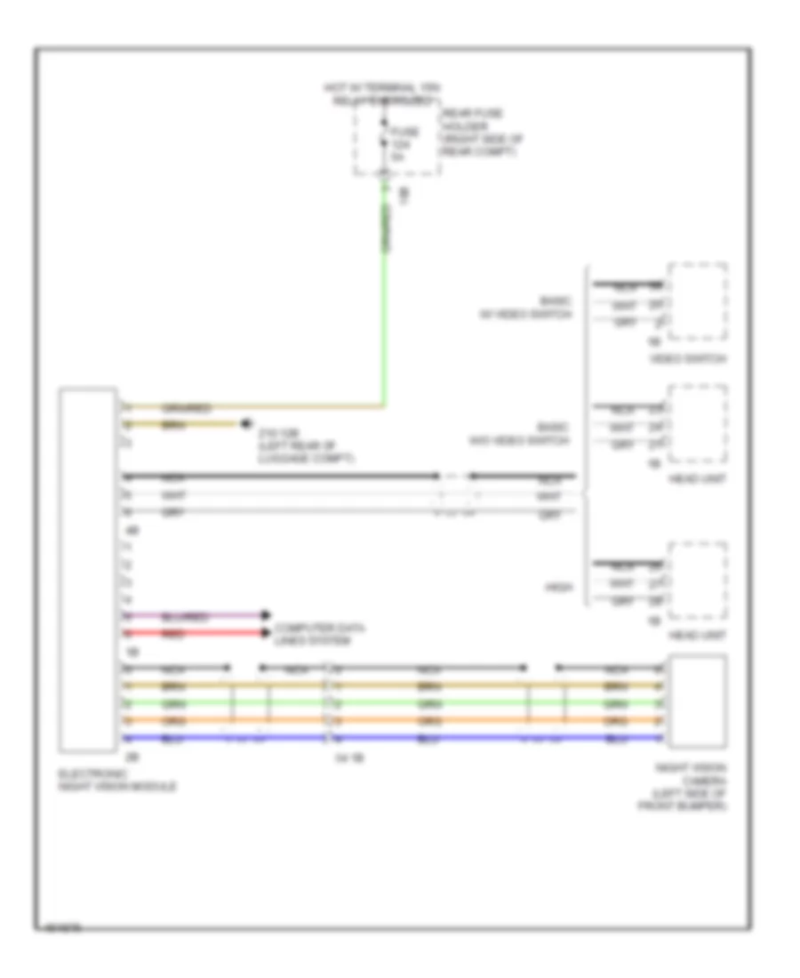
- Electronic night vision module
- Electronic transmission control
- Fuel tank pressure sensor
- Head unit
- Hifi amplifier
- Independent heating fuel metering pump
- Infotainment fan
- Interface box
- Left front entrance light
- Left outer tail light
- Left rear damper satellite
- Left rear entrance light
- Left rear footwell light
- Left rear lighting speaker 2
- Lockout circuit
- Luggage compartment seat adjustment switch cluster
- Natural vacuum leak detection
- Nca
- Nitrogen oxide sensor after scr catalytic converter
- Nitrogen oxide sensor before scr catalytic converter
- Passenger's side rear seat adjustment switch cluster
- Rear center armrest light
- Rear compartment controller
- Rear compartment display
- Rear eject box 1
- Rear eject box 2
- Rear seat entertainment
- Reverse gear switch
- Right rear
- Right rear footwell light
- Right rear lighting speaker 2
- S91 1b
- S92 1b
- Top hifi amplifier
- Touch box
- Transfer box
- Usb hub
- Video module
- Video switch
- W/ hifi amplifier
- W/ rear lumbar seat
- W/ top hifi amplifier
- W/o rear lumbar seat
- X10 1b
- X167 1b
- X2042 (3.0l turbo diesel)
- X230 1b
- X257 1b
- X6053
- X81 1b
- X82 1b
- Z10 12b (left rear of luggage compt)
- Z10 13b (sedan: right "c" pillar) (hatchback: right side of cargo area)
- Z10 14b (sedan: left "c" pillar) (hatchback: left side of cargo area)
- Z10 51b
- Z10 9b (left kick panel)
Ground Distribution Wiring Diagram (4 of 6) for BMW 535i GT 2014
List of elements for Ground Distribution Wiring Diagram (4 of 6) for BMW 535i GT 2014:
- (3.0l turbo diesel) scr control unit
- (3.0l turbo) a/c compressor
- (gt) automatic luggage compartment lid actuation
- (gt) fuel pump control (ekps)
- (if equipped) rear driver's side seat belt buckle contact
- (if equipped) rear passenger's side seat belt buckle contact
- (w/ panorama glass roof) left rear interior light
- (w/ panorama glass roof) right rear interior light
- (w/o rear compartment automatic climate control) driver's side rear seat heating switch
- (w/o rear compartment automatic climate control) passenger's side rear seat heating switch
- 12v connection 2
- Active steering servo motor shield
- Active tank fuel level sensor
- Auc sensor
- Automatic air recirculation control (auc) sensor
- Basic variant roof functions module
- Boot lid lift
- Boot lid/ tailgate lock
- Camera-based driver assistance systems
- Center console operating unit
- Center rear seat belt buckle contact
- Central gateway module
- Compressor relay
- Crash safety module
- Diagnosis socket
- Dosing line heating
- Driver's seat belt buckle contact
- Electrochromic interior rear view mirror
- Electronic ride height control
- Exterior boot lid button
- Footwell module
- High variant roof functions module
- Hotel position switch
- Integrated chassis management
- Lane change warning
- Left front vanity mirror switch
- Left inner tail light
- Left license plate light
- License plate light
- Nca
- Parking brake button
- Parking brake control unit
- Parking distance control
- Parking maneuvering assistant
- Passenger's seat belt buckle contact
- Passenger's seat occupancy deactivation sensor
- Premium top hifi amplifier
- Rear compartment automatic climate control
- Rear compartment display 2
- Rear lid lock 2
- Right front vanity mirror switch
- Right inner tail light
- Right license plate light
- Sedan
- Siren w/ tilt alarm sensor
- W/ automatic soft close system
- W/ basic variant
- W/ high variant
- W/ rear lid button
- W/o automatic soft close system
- Washer fluid level switch
- X12 1b
- X14 1b
- X231 1b
- X448 1b
- X6454 (rear of engine block)
- Y25 1b
- Z10 10b (under front of center console)
- Z10 11b (right kick panel)
- Z10 17b (right side of cargo area)
- Z10 18b
- Z10 20b (top of right "c" pillar)
- Z10 22b (left kick panel)
- Z10 50b
- Z10 58b
Ground Distribution Wiring Diagram (5 of 6) for BMW 535i GT 2014
List of elements for Ground Distribution Wiring Diagram (5 of 6) for BMW 535i GT 2014:
- (2.0l turbo) ignition coil cylinder 3
- (2.0l turbo) ignition coil cylinder 4
- (4.4l turbo) ignition coil cylinder 2
- (4.4l turbo) ignition coil cylinder 3
- (4.4l turbo) ignition coil cylinder 4
- (except m5) auxiliary water pump
- (hybrid) starter motor generator
- (m5) auxiliary water pump
- (m5) charge air cooler coolant pump
- (m5) charge air cooler coolant pump 2
- (not used)
- 2.0l turbo
- 3.0l turbo
- A/c compressor (electrical)
- Active cruise control
- Automatic transmission
- Bonnet contact switch
- Brake pad wear sensor
- Center washer nozzle heater
- Digital diesel electronics
- Electric fan
- Electronic transmission control
- Except m5
- Fuel filter heating
- High range fanfare horn
- Hybrid
- Independent auxiliary heater
- Independent heating coolant changeover valve
- Left fog light
- Left front
- Left front damper satellite
- Left front direction indicator light repeater
- Left headlight
- Left targeted illumination
- Left washer nozzle heater
- Low range fanfare horn
- M254 1b
- Nca
- Oil level switch
- Radiator shutter center drive unit
- Right fog light
- Right front damper satellite
- Right headlight
- Right targeted illumination
- Right washer nozzle heater
- Sedan
- Starter motor generator
- Terminating resistor 3
- Transmission oil pump
- Vehicle sound generator
- W/ alarm system & automatic air flap control
- W/ sport package
- W/o alarm system & automatic air flap control
- W/o sport package
- Water valve assembly
- Wiper module
- X148 1b
- X149 1b
- X149 2b
- X149 3b
- X187 1b
- X217 1b
- X218 2b
- X252 1b
- X690 1b
- Y21 1b
- Z10 15b (left rear of engine compt)
- Z10 2b (lower left front of engine compt)
- Z10 3b (lower right front of engine compt)
- Z6000 2b
Ground Distribution Wiring Diagram (6 of 6) for BMW 535i GT 2014
List of elements for Ground Distribution Wiring Diagram (6 of 6) for BMW 535i GT 2014:
- (2.0l turbo) a/c compressor
- (2.0l turbo) digital motor electronics
- (2.0l turbo) reverse gear switch
- (2.0l turbo) transfer box
- (3.0l turbo diesel) electronic transmission control
- (4.4l turbo)
- (4.4l turbo) digital motor electronics
- (4.4l turbo) ignition coil cylinder 5
- (4.4l turbo) ignition coil cylinder 6
- (4.4l turbo) ignition coil cylinder 7
- (4.4l turbo) ignition coil cylinder 8
- (4.4l turbo) transfer box
- (535i gt & 535i gt xdrive) electric coolant pump
- (535i gt & 535i gt xdrive) intercooler coolant pump
- (550i, 550i gt, 550i gt xdrive & 550i xdrive) electronic transmission control
- (550i, 550i xdrive, 550i gt & 550i gt xdrive) a/c compressor
- (a/t) transfer box
- (hybrid) accumulator management electronics
- (hybrid) machine electronics electric
- (hybrid) rotor position sensor
- (hybrid) starter/ alternator electronics
- (m/t) input speed sensor
- (m/t) transfer box
- (m/t) transmission fluid pump
- (m/t) transmission oil pump relay
- (m5) a/c compressor
- (right side of rear compt) rear fuse holder
- (w/o noise suppressor filter) rear lid lock 2
- Bistable relay
- Contact free tailgate opening evaluation
- Contact free tailgate opening evaluation electronics
- Cooler box
- Dc/dc converter
- Dynamic stability control (dsc)
- Electric coolant pump
- Electronic transmission control
- Electronics
- Except m5
- Fully automatic towing hitch
- Gearbox input-speed sensor
- Intercooler coolant pump
- M6 1b
- Nca
- Noise suppressor filter
- Oil condition sensor
- Power tailgate acoustic sensor
- Pressure control
- Rear air conditioning system blower output stage
- Rear compartment air conditioning system
- Rear window defogger
- Rear window defogger relay
- Rear window locking
- Rear wiper
- Reverse gear switch
- Right outer taillight
- Right rear damper satellite
- Terminal 15n relay
- Terminal 30b relay
- Terminator resistor 2
- Tire
- Trailer module
- Trailer socket
- Trailer socket switch
- Transmission oil pump relay
- Turbocharger coolant pump
- W/ twin clutch gear box
- W/o twin clutch gear box
- X268 1b
- X6343
- X6460
- X697 1b
- X6985
- X7517 (right front of engine compt)
- X8532
- Z10 23b
- Z10 4b (left kick panel)
- Z10 8b (right side of cargo area)
- Z6000 3b
- Z6000 4b
- Z6000 5b
- Zero-gear sensor
HEADLIGHTS
Headlights Wiring Diagram, with LED Headlamps (1 of 2) for BMW 535i GT 2014
List of elements for Headlights Wiring Diagram, with LED Headlamps (1 of 2) for BMW 535i GT 2014:
- (left end of dash) central gateway module
- (left kick panel) z10 22b
- 10b
- Computer data lines system
- Design light
- Electrochromic interior rearview mirror
- Electronics junction box
- Footwell module (left kick panel)
- Fuse 10a
- Fuse 15a
- Fuse 30a
- Fuse 40a
- Fuse 5a
- Gnd
- Headlight beam height control drive unit
- Headlight driver module
- High beam assistant sensor & control
- High beam headlight
- Hot at all times
- Hot w/ bi-stable relay energized
- Hot w/ terminal 15n relay energized
- Junction box (right side of dash)
- K-can bus sig
- Led main light module
- Left fog light
- Left headlight
- Light switch unit
- Lin bus sig
- Low beam headlight
- Outer fan
- Pnk
- Pwr sply
- Red
- Right fog light
- Sedan
- Sedan w/ adaptive light control
- Sedan w/o adaptive light control
- Side lights/ daytime driving light
- Sply 15
- Steering column switch cluster
- Swivel module
- Trn sig/ hi beam sw
- W/ sport package
- W/o sport package
- X149 1b
- X149 2b
- Z10 22b (left kick panel)
- Z10 2b (lower left front of engine compt)
- Z10 5b (left kick panel)
Headlights Wiring Diagram, with LED Headlamps (2 of 2) for BMW 535i GT 2014
List of elements for Headlights Wiring Diagram, with LED Headlamps (2 of 2) for BMW 535i GT 2014:
- (lower left center of dash) car access system
- (right side of cargo area) z10 17b
- 11b
- Basic variant roof function module
- Computer data lines system
- Design light
- Dynamic stability control (under right front of vehicle)
- Except m5
- Fuse 10a
- Fuse 15a
- Fuse 40a
- Fuse 5a
- Fuse 7.5a
- Headlight driver module
- Headlight range control drive unit
- High beam headlight
- High variant roof functions module
- Hot at all times
- Hot w/ bi-stable
- Hot w/ bi-stable relay energized
- Hot w/ terminal 30b relay energized
- Interior lights system
- Junction box (right side of dash)
- Led ind
- Led main light module
- Low beam headlight
- Outer fan
- Parking brake button
- Parking brake control module (center rear of luggage compt)
- Power distribution system
- Rain/light/ condensation/ solar sensor (rain sensor: front center of roof)
- Rear fuse holder (right side of rear compt)
- Red
- Relay energized
- Right headlight
- Sedan
- Sedan w/ adaptive light control
- Sedan w/o adaptive light control
- Side lights/ daytime driving light
- Sw sig
- Swivel module
- W/ basic variant
- W/ high variant
- Z10 11b (right kick panel)
- Z10 3b (lower right front of engine compt)
Headlights Wiring Diagram, without LED Headlamps (1 of 3) for BMW 535i GT 2014
List of elements for Headlights Wiring Diagram, without LED Headlamps (1 of 3) for BMW 535i GT 2014:
- (left end of dash) central gateway module
- 10b
- Bi-xenon
- Computer data lines system
- Cornering light
- Electrochromic interior rearview mirror
- Electronics junction box
- Footwell module (left kick panel)
- Fuse 10a
- Fuse 30a
- Fuse 40a
- Fuse 5a
- Gnd
- Gt & sedan w/o adaptive light control
- Headlight driver module
- Headlight high beam drive control unit
- Hi beam
- High beam
- High beam assistant sensor & control
- High beam sw
- Hot w/ bi-stable relay energized
- Hot w/ terminal 15n relay energized
- Junction box (right side of dash)
- K-can bus sig
- Left fog light
- Left headlight
- Lin bus sig
- Low beam
- Parking light/ daytime driving light
- Pnk
- Pwr sply
- Red
- Right fog light
- Sedan
- Sedan w/ adaptive light control
- Shutter bi-xenon
- Sply 15
- Steering column switch cluster
- Swivel module
- W/ sport package
- W/ xenon
- W/o sport package
- W/o xenon
- X149 1b
- X149 2b
- Xenon lamp
- Xenon light module
- Z10 22b (left kick panel)
- Z10 2b (lower left front of engine compt)
- Z10 5b (left kick panel)
Headlights Wiring Diagram, without LED Headlamps (2 of 3) for BMW 535i GT 2014
List of elements for Headlights Wiring Diagram, without LED Headlamps (2 of 3) for BMW 535i GT 2014:
- (lower left center of dash) car access system
- Adaptive light control
- Cornering light
- Fuse 10a
- Fuse 40a
- Gt & sedan w/o adaptive light control
- Headlight driver module
- Headlight high beam drive control unit
- High beam
- Hot w/ bi-stable relay energized
- Light switch unit
- Low beam
- Parking light/daytime driving light
- Rear fuse holder (right side of rear compt)
- Right headlight
- Sedan
- Sedan w/
- Shutter bi-xenon
- Swivel module
- W/ xenon
- W/o xenon
- Xenon lamp
- Xenon light module
- Z10 3b (lower right front of engine compt)
Headlights Wiring Diagram, without LED Headlamps (3 of 3) for BMW 535i GT 2014
List of elements for Headlights Wiring Diagram, without LED Headlamps (3 of 3) for BMW 535i GT 2014:
- (rain sensor: front center of roof)
- (right side of cargo area) z10 17b
- 11b
- Basic variant roof function module
- Computer data lines system
- Dynamic stability control (under right front of vehicle)
- Except m5
- Fuse 5a
- Fuse 7.5a
- High variant roof function module
- Hot at all times
- Hot w/ terminal 30b relay energized
- Interior lights system
- Junction box (right side of dash)
- Led ind
- Parking brake button
- Parking brake control module (center rear of luggage compt)
- Power distribution system
- Rain/light condensation/ solar sensor
- Rear fuse holder (right side of rear compt)
- Red
- Sw sig
- W/ basic variant
- W/ high variant
- Z10 11b (right kick panel)
HORN
Horn Wiring Diagram for BMW 535i GT 2014
List of elements for Horn Wiring Diagram for BMW 535i GT 2014:
- 10b
- 11b
- 15b
- Early production
- Electronic steering wheel module (part of steering wheel)
- Electronics junction box
- Fuse 10a
- Fuse 15a
- Fuse 250a
- Fuse box (under spare tire)
- High range fanfare horn (right front wheelwell)
- Horn button
- Horn relay
- Hot at all times
- Junction box (right side of dash)
- Late production
- Low range fanfare horn (right front wheel- well)
- Low range fanfare horn (right front wheelwell)
- Red
- Right multi-function steering wheel switch block
- Steering column switch cluster
- Terminal 30b relay
- X149 1b
INSTRUMENT CLUSTER
Electronic Night Vision Wiring Diagram for BMW 535i GT 2014
List of elements for Electronic Night Vision Wiring Diagram for BMW 535i GT 2014:
- 10b
- Basic w/ video switch
- Basic w/o video switch
- Computer data lines system
- Electronic night vision module
- Fuse 5a
- Head unit
- High
- Hot w/ terminal 15n relay energized
- Nca
- Night vision camera (left side of front bumper)
- Rear fuse holder (right side of rear compt)
- Red
- Video switch
- X4 1b
- Z10 12b (left rear of luggage compt)
Instrument Cluster Wiring Diagram for BMW 535i GT 2014
List of elements for Instrument Cluster Wiring Diagram for BMW 535i GT 2014:
- A34 1b
- A34 2b
- A34 3b
- Car access system (lower left center of dash)
- Computer data lines system
- Coolant level switch (right side of engine compt)
- Electronics junction box
- Fuel level sensor
- Fuel level sensor 2
- Fuse 10a
- Fuse 5a
- Head-up display
- Hot at all times
- Hot w/ terminal 30b relay energized
- Instrument cluster control unit
- Junction box (right side of dash)
- K can2-h
- K can2-l
- Nca
- Outside temperature sensor (under right front of vehicle)
- Red
- Sound systems
- Wake up sig
- X149 1b
- X94 1b
- Z1 10b
- Z10 6b (right kick panel)
- Z10 9b (left kick panel)
INTERIOR LIGHTS
Courtesy Lamps Wiring Diagram (1 of 3) for BMW 535i GT 2014
List of elements for Courtesy Lamps Wiring Diagram (1 of 3) for BMW 535i GT 2014:
- Ambient light
- Electronics junction box
- Fuse 5a
- Fuse 7.5a
- Glove compartment light
- Glove compartment light switch
- High variant roof functions module (w/ high variant) basic variant roof functions module (w/ basic variant)
- Hot at all times
- Hot w/ terminal 30b relay energized
- Instrument illumination circuit
- Interior light
- Junction box (right side of dash)
- Left front vanity mirror light
- Left front vanity mirror switch
- Left map reading light
- Power distribution system
- Rear interior light
- Red
- Right front vanity mirror light
- Right front vanity mirror switch
- Right map reading light
- W/ basic variant
- W/ high variant
- Z10 11b (right kick panel)
Courtesy Lamps Wiring Diagram (2 of 3) for BMW 535i GT 2014
List of elements for Courtesy Lamps Wiring Diagram (2 of 3) for BMW 535i GT 2014:
- Boot lid/ tailgate lock
- Boot lid/tailgate luggage compartment light
- Fuse 5a
- Hot w/ terminal 30b relay energized
- Inside rear lid button
- Left front entrance light
- Left rear entrance light
- Left rear footwell light
- Luggage compartment light
- Luggage compartment light 2
- Noise suppression filter
- Rear fuse holder (right side of rear compt)
- Rear lid central arrest button
- Rear lid lock 2
- Rear lid luggage compartment light 2
- Right front entrance light
- Right rear entrance light
- Right rear footwell light
- W/ noise suppressor filter
- W/o noise suppressor filter
- Z10 13b (right side of cargo area)
- Z10 14b (left side of cargo area)
- Z10 17b (right side of cargo area)
- Z10 20b (top of right "c" pillar)
- Z10 5b (left kick panel)
- Z10 6b (right kick panel)
- Z10 8b (right side of cargo area)
Courtesy Lamps Wiring Diagram (3 of 3) for BMW 535i GT 2014
List of elements for Courtesy Lamps Wiring Diagram (3 of 3) for BMW 535i GT 2014:
- (left kick panel) z10 5b
- Computer data lines system
- Courtesy lighting
- Driver's door entrance light
- Electronics junction box
- Entrance lt
- Footwell module (left kick panel)
- Fuse 40a
- Gnd
- Hot w/ bi-stable relay energized
- Interior lt
- Junction box (right side of dash)
- K-can bus sig
- Left footwell lt
- Left front footwell light
- Passenger's door entrance light
- Pwr sply
- Rear driver's side courtesy lighting
- Rear driver's side entry light
- Rear passenger's side courtesy lighting
- Rear passenger's side entry light
- Right footwell lt
- Right front footwell light
- Signal, switch
- Switch signal
- X28 1b
- X5 1b
- X8 1b
- X9 1b
- Z10 5b (left kick panel)
- Z10 6b (right kick panel)
Instrument Illumination Wiring Diagram (1 of 2) for BMW 535i GT 2014
List of elements for Instrument Illumination Wiring Diagram (1 of 2) for BMW 535i GT 2014:
- (right kick panel) z10 6b
- (under center console) integrated chassis management
- Ambient light
- Ambient lt
- Basic variant roof functions module
- Center console operating unit
- Center front ventilation grille
- Central locking button operating unit hazard warning switch
- Computer data lines system
- Driver's side dashboard decor strip lighting
- Dvd changer (left side of rear compt)
- Footwell module (left kick panel)
- Fuse 10a
- Fuse 5a
- Gnd
- Ground
- Heating/air conditioning system
- High variant roof functions module
- Hot w/ bi-stable relay energized
- Interior rear lid button
- Junction box (right side of dash)
- Junction box electronics
- K-can bus sig
- Left front ventilation grille
- Left side center console panel lighting
- Light switch unit
- Lin bus sig
- Parking brake button
- Passenger's door pocket lighting
- Passenger's door power window switch
- Passenger's door trim panel lighting
- Passenger's side dashboard decor strip lighting
- Passenger's side dashboard decor strip lighting 2
- Pwr sply
- Rear interior light
- Rear seat entertainment
- Right front ventilation grille
- Right side center console panel lighting
- W/ basic variant
- W/ high variant
- X5 1b
- X501 1b
- Z10 10b (under front of center console)
- Z10 11b (right kick panel)
- Z10 12b (left rear of luggage compt)
- Z10 17b (right side of cargo area)
- Z10 5b (left kick panel)
- Z10 6b (right kick panel)
Instrument Illumination Wiring Diagram (2 of 2) for BMW 535i GT 2014
List of elements for Instrument Illumination Wiring Diagram (2 of 2) for BMW 535i GT 2014:
- Computer data lines system
- Driver's door panel lighting
- Driver's door pocket lighting
- Front center armrest light
- Fuse 5a
- Hot w/ terminal 15n relay energized
- Left backrest lighting
- Left targeted illumination
- Rear center armrest light
- Rear compartment automatic climate control
- Rear compartment ventilation grille
- Rear driver's side door panel lighting
- Rear driver's side door pocket lighting
- Rear driver's side power window switch (w/o electrically operated roller sun blinds)
- Rear fuse holder (right side of rear compt)
- Rear passenger's side door panel lighting
- Rear passenger's side door pocket lighting
- Rear passenger's side power window switch (w/o electrically operated roller sun blinds)
- Right backrest lighting
- Right targeted illumination
- W/ sports package
- W/o sports package
- X12 1b
- X14 1b
- X148 1b
- X149 1b
- X149 3b
- X187 1b
- X28 1b
- X8 1b
- X9 1b
- Z10 13b (right side of cargo area)
- Z10 2b (lower left front of engine compt)
- Z10 3b (lower right front of engine compt)
- Z10 5b (left kick panel)
- Z10 6b (right kick panel)
MEMORY SYSTEMS
Driver"s Memory Seat Wiring Diagram (1 of 2) for BMW 535i GT 2014
List of elements for Driver"s Memory Seat Wiring Diagram (1 of 2) for BMW 535i GT 2014:
- Actuator motor
- Angle
- Bus sig
- Computer data lines system
- Depth
- Driver's door seat switch cluster
- Driver's seat angle adjustment drive (under driver's seat)
- Driver's seat depth adjustment drive (w/ multi-function seat or sport seat) (under driver's seat)
- Driver's seat forward/ backward adjustment drive (under driver seat)
- Driver's seat height adjustment drive (under driver's seat)
- Driver's seat module (under right side of seat)
- Footwell module (left kick panel)
- For/back
- Fuse 10a
- Fuse 30a
- Fuse 7.5a
- Gnd
- Gnd hall sens
- Hall sens sig
- Hall sensor
- Height
- Hot w/ terminal 30b relay energized
- Junction box (right side of dash)
- Nca
- Power distribution system
- Pwr sply
- Red
- Seat backrest
- Seat cushion
- Seats system
- Sig temp sens
- X14 1b
- Z10 5b (left kick panel)
Driver"s Memory Seat Wiring Diagram (2 of 2) for BMW 535i GT 2014
List of elements for Driver"s Memory Seat Wiring Diagram (2 of 2) for BMW 535i GT 2014:
- (w/ multi-function seat) driver's side seat adjustment switch cluster
- (w/o multi-function seat) driver's side seat adjustment switch cluster
- Actuator motor
- Back act fan
- Back angle
- Back gnd fan
- Back head
- Back width
- Bus sig
- Cam operated
- Driver's seat backrest angle adjustment drive
- Driver's seat backrest head adjustment drive (w/ multi-function seat) (left side of seat back)
- Driver's seat backrest width adjustment drive (w/ multi-function seat or sport seat) (bottom right of seat back)
- Driver's seat headrest height adjustment drive
- Driver's seat module (under right side of seat)
- Gnd
- Hall sens gnd
- Hall sens sig
- Hall sensor
- Headrest
- Lum sup active
- Lum sup gnd
- Lum sup vlv 1
- Lum sup vlv 2
- Lum sup vlv 3
- Lum sup vlv 4
- Lum sup volt
- Pressure gnd
- Pwr sply
- Red
- Seat act fan
- Seat gnd fan
- Seats system
- Vlv block gnd
- Volt sply
- Z10 5b (left kick panel)
Left Memory Rear Seat Wiring Diagram (1 of 2) for BMW 535i GT 2014
List of elements for Left Memory Rear Seat Wiring Diagram (1 of 2) for BMW 535i GT 2014:
- Actuator motor
- Bus sig
- Computer data lines system
- Footwell module (left kick panel)
- For/back
- Fuse 30a
- Fuse 5a
- Gnd
- Gnd hall sens
- Hall sens gnd
- Hall sens sig
- Hall sensor
- Headrest
- Hot w/ terminal 30b relay energized
- Power distribution system
- Pwr sply
- Rear driver's side door seat switch cluster
- Rear driver's side headrest height adjustment drive
- Rear driver's side seat forward/ backward adjustment drive
- Rear driver's side seat module
- Rear fuse holder (right side of rear compt)
- Seat backrest
- Seat cushion
- Seats system
- Sig temp sens
- X8 1b
- Z10 13b (hatch back: right side of cargo area) (sedan: right "c" pillar)
- Z10 5b (left kick panel)
Left Memory Rear Seat Wiring Diagram (2 of 2) for BMW 535i GT 2014
List of elements for Left Memory Rear Seat Wiring Diagram (2 of 2) for BMW 535i GT 2014:
- Actuator motor
- Back act fan
- Back angle
- Back gnd fan
- Back width
- Bus sig
- Fuse 5a
- Gnd
- Hall sens gnd
- Hall sens sig
- Hall sensor
- Hot w/ terminal 30b relay energized
- Luggage compartment seat adjustment switch cluster
- Lum sup gnd
- Lum sup vlv 1
- Lum sup vlv 2
- Lum sup vlv 3
- Lum sup vlv 4
- Lum sup volt
- Nca
- Power distribution system
- Pwr sply
- Rear driver's side backrest angle adjustment drive
- Rear driver's side backrest head adjustment drive
- Rear driver's side seat adjustment switch cluster
- Rear driver's side seat module
- Rear fuse holder (right side of rear compt)
- Red
- S91 1b
- Seat act fan
- Seat gnd fan
- Seats system
- Vlv block gnd
- Volt sply
- X257 1b
- X81 1b
- Z10 13b (hatch back: right side of cargo area) (sedan: right "c" pillar)
- Z10 14b (hatch back: left side of cargo area) (sedan: left "c" pillar)
Memory Mirrors Wiring Diagram, with LIN bus Function for BMW 535i GT 2014
List of elements for Memory Mirrors Wiring Diagram, with LIN bus Function for BMW 535i GT 2014:
- (left kick panel) z10 5b
- Adjustment drive
- Bus sig
- Computer data lines system
- Driver's door switch block
- Footwell module (left kick panel)
- Fuse 7.5a
- Hot w/ terminal 30b relay energized
- In drive
- Junction box (right side of dash)
- Left exterior mirror
- Mirror fold- m
- Mirror heater
- Navigation system
- Nca
- Outside mirror camera
- Right exterior mirror
- X28 1b
- X5 1b
- Z10 6b (right kick panel)
Memory Mirrors Wiring Diagram, without LIN bus Function for BMW 535i GT 2014
List of elements for Memory Mirrors Wiring Diagram, without LIN bus Function for BMW 535i GT 2014:
- (left kick panel) z10 5b
- Adjustment drive
- Bus sig
- Computer data lines system
- Driver's door switch block
- Electronics junction box
- Footwell module (left kick panel)
- Fuse 7.5a
- Hot w/ terminal 30b relay energized
- Junction box (right side of dash)
- Left exterior mirror
- Mirror heater
- Right exterior mirror
- X28 1b
- X5 1b
- Z10 5b (left kick panel)
- Z10 6b (right kick panel)
Passenger"s Memory Seat Wiring Diagram (1 of 2) for BMW 535i GT 2014
List of elements for Passenger"s Memory Seat Wiring Diagram (1 of 2) for BMW 535i GT 2014:
- Actuator motor
- Angle
- Bus sig
- Computer data lines system
- Depth
- Footwell module (left kick panel)
- For/back
- Fuse 10a
- Fuse 30a
- Fuse 7.5a
- Gnd
- Gnd hall sens
- Hall sens sig
- Hall sensor
- Height
- Hot w/ terminal 30b relay energized
- Junction box (right side of dash)
- Nca
- Passenger's door seat switch cluster
- Passenger's seat angle adjustment drive (under front passenger's seat)
- Passenger's seat depth adjustment drive (w/ multi-function seat or sport seat) (under front passenger's seat)
- Passenger's seat forward/ backward adjustment drive
- Passenger's seat height adjustment drive (under front passenger's seat)
- Passenger's seat module (under passenger's seat)
- Power distribution system
- Pwr sply
- Red
- Seat backrest
- Seat cushion
- Seats system
- Sig temp sens
- X12 1b
- Z10 6b (right kick panel)
Passenger"s Memory Seat Wiring Diagram (2 of 2) for BMW 535i GT 2014
List of elements for Passenger"s Memory Seat Wiring Diagram (2 of 2) for BMW 535i GT 2014:
- (w/ multi-function seat) passenger's side seat adjustment switch cluster
- (w/o multi-function seat) passenger's side seat adjustment switch cluster
- Actuator motor
- Back act fan
- Back angle
- Back gnd fan
- Back head
- Back width
- Bus sig
- Cam operated
- Cam sw sig
- Gnd
- Hall sens gnd
- Hall sens sig
- Hall sensor
- Headrest
- Lum sup active
- Lum sup gnd
- Lum sup vlv 1
- Lum sup vlv 2
- Lum sup vlv 3
- Lum sup vlv 4
- Lum sup volt
- Passenger's seat backrest angle adjustment drive (right side of passenger's seat back)
- Passenger's seat backrest head adjustment drive (w/ multi-function seat) (right side of seat back)
- Passenger's seat backrest width adjustment drive (w/ multi-function seat or sport seat) (bottom left of seat back)
- Passenger's seat headrest height adjustment drive
- Passenger's seat module (under passenger's seat)
- Pressure gnd
- Pwr sply
- Red
- Seat act fan
- Seat gnd fan
- Seat sw gnd
- Seat sw sply
- Seats system
- Sw sig
- Vlv block gnd
- Volt sply
- Z10 6b (right kick panel)
Right Memory Rear Seat Wiring Diagram (1 of 2) for BMW 535i GT 2014
List of elements for Right Memory Rear Seat Wiring Diagram (1 of 2) for BMW 535i GT 2014:
- Actuator motor
- Bus sig
- Computer data lines system
- Footwell module (left kick panel)
- For/back
- Fuse 30a
- Fuse 5a
- Gnd
- Gnd hall sens
- Hall sens sig
- Hall sensor
- Headrest
- Hot w/ terminal 30b relay energized
- Power distribution system
- Pwr sply
- Rear fuse holder (right side of rear compt)
- Rear passenger's side door seat switch cluster
- Rear passenger's side headrest height adjustment drive
- Rear passenger's side seat forward/ backward adjustment drive
- Rear passenger's side seat module
- Seat backrest
- Seat cushion
- Seats system
- Sig temp sens
- X9 1b
- Z10 13b (hatch back: right side of cargo area) (sedan: right "c" pillar)
- Z10 6b (right kick panel)
Right Memory Rear Seat Wiring Diagram (2 of 2) for BMW 535i GT 2014
List of elements for Right Memory Rear Seat Wiring Diagram (2 of 2) for BMW 535i GT 2014:
- Actuator motor
- Back act fan
- Back angle
- Back gnd fan
- Back width
- Bus sig
- Fuse 5a
- Gnd
- Hall sens gnd
- Hall sens sig
- Hall sensor
- Hot w/ terminal 30b relay energized
- Luggage compartment seat adjustment switch cluster
- Lum sup gnd
- Lum sup vlv 1
- Lum sup vlv 2
- Lum sup vlv 3
- Lum sup vlv 4
- Lum sup volt
- Nca
- Power distribution system
- Pwr sply
- Rear fuse holder (right side of rear compt)
- Rear passenger's side backrest angle adjustment drive
- Rear passenger's side backrest head adjustment drive
- Rear passenger's side seat adjustment switch cluster
- Rear passenger's side seat module
- Red
- S92 1b
- Seat act fan
- Seat gnd fan
- Seats system
- Shield
- Vlv block gnd
- Volt sply
- X10 1b
- X82 1b
- Z10 13b (hatch back: right side of cargo area) (sedan: right "c" pillar)
- Z10 14b (hatch back: left side of cargo area) (sedan: left "c" pillar)
Steering Column Memory Wiring Diagram for BMW 535i GT 2014
List of elements for Steering Column Memory Wiring Diagram for BMW 535i GT 2014:
- 10b
- Bus sig
- Column
- Computer data lines system
- Driver's door seat switch cluster
- Footwell module (left kick panel)
- Fuse 10a
- Fuse 30a
- Fuse 7.5a
- Gnd
- Hall sens
- Hall sens sig
- Hot w/ bistable relay energized
- Hot w/ terminal 15n relay energized
- Hot w/ terminal 30b relay energized
- Junction box (right side of dash)
- Pnk
- Pwr sply
- Red
- Sply
- Steering column adjustment motor (right of steering column)
- Steering column inclination motor
- Steering column switch cluster
- Steering wheel heater & steering column adjustment switch
- Z10 5b (left kick panel)
NAVIGATION
All Around Vision Camera Wiring Diagram for BMW 535i GT 2014
List of elements for All Around Vision Camera Wiring Diagram for BMW 535i GT 2014:
- (left rear of luggage compt) z10 12b
- 10b
- All-round vision camera (left rear of luggage compt)
- Computer data lines system
- Exterior mirror camera
- Fuse 5a
- Head unit
- Hot w/ terminal 15n relay energized
- Left bumper camera (left end of front fascia)
- Left exterior mirror
- Nca
- Rear fuse holder (right side of rear compt)
- Red
- Reversing camera (center rear of trunk lid)
- Right bumper camera (right end of front fascia)
- Right exterior mirror
- Sedan
- Video switch
- W/ video switch
- W/o video switch
- X198 1b
- X199 1b
Lane Departure Warning Wiring Diagram, with Camera for BMW 535i GT 2014
List of elements for Lane Departure Warning Wiring Diagram, with Camera for BMW 535i GT 2014:
- A34 3b
- Camera-based driver assistance systems (left end of dash)
- Camera-based driver support systems heating (left end of dash)
- Computer data lines system
- Driver assistance systems operating unit
- Electronics junction box
- Footwell module (left kick panel)
- Fuse 5a
- Hot w/ bistable relay energized
- Hot w/ terminal 15n relay energized
- Junction box (right side of dash)
- Lane departure warning camera (base of interior rearview mirror assembly)
- Nca
- Red
- Z1 7b
- Z10 22b (left kick panel)
Lane Departure Warning Wiring Diagram, without Camera for BMW 535i GT 2014
List of elements for Lane Departure Warning Wiring Diagram, without Camera for BMW 535i GT 2014:
- Central gateway module (left end of dash)
- Computer data lines system
- Footwell module (left kick panel)
- Fuse 5a
- Hot w/ terminal 15n relay energized
- Lane departure warning camera (base of interior rearview mirror assembly)
- Pnk
- Rear fuse holder (right side of rear compt)
- Slave lane departure warning
- Steering column switch cluster
- Z10 17b (right side of cargo area)
Navigation Wiring Diagram, with Hifi Radio without Active Sound Design (1 of 2) for BMW 535i GT 2014
List of elements for Navigation Wiring Diagram, with Hifi Radio without Active Sound Design (1 of 2) for BMW 535i GT 2014:
- (left rear of luggage compt) z10 12b
- (or red)
- (sedan: bottom of left "c" pillar) noise suppression filter
- 10b
- 11b
- 15b
- 16b
- Aerial diversity
- All-round vision camera (left rear of luggage compt)
- Aux-in connection
- Central gateway module (left end of dash)
- Computer data lines system
- Dvd changer (left side of rear compt)
- Entertainment
- Fuse 10a
- Fuse 15a
- Fuse 5a
- Glove compartment usb connection
- Head unit
- Hot w/ terminal 30b relay energized
- Interior lights system
- Most data bus circuit
- Nca
- Power distribution system
- Rear fuse holder (right side of rear compt)
- Rear seat entertainment
- Rear seat entertainment circuit
- Rear window aerial
- Red
- Roof aerial
- Video module (sedan: left side of rear compt)
- Video switch
- W/ dvd changer
- W/ night vision camera
- W/ phase diversity
- W/ rear seat
- W/ scan diversity
- W/ video module
- W/ video switch
- W/o night vision camera
- W/o video switch
- W/o video switch & all round vision camera
- W/o video switch & w/ all round vision camera
- W/o video switch, night vision camera & w/ all round vision camera
- X188 1b
Navigation Wiring Diagram, with Hifi Radio without Active Sound Design (2 of 2) for BMW 535i GT 2014
List of elements for Navigation Wiring Diagram, with Hifi Radio without Active Sound Design (2 of 2) for BMW 535i GT 2014:
- (lower left front of engine compt)
- Base plate
- Central information display
- Computer data lines system
- Electronic night vision module
- Front center mid- range speaker
- Front center tweeter
- Fuse 30a
- Fuse 5a
- Head unit
- Hifi amplifier (sedan: left side of rear compt)
- Hot at all times
- Hot w/ terminal 15n relay energized
- Hot w/ terminal 30b relay energized
- Junction box (right side of dash)
- Left front mid- range speaker
- Left front tweeter
- Left front woofer
- Left rear mid range speaker (gt) left 2b rear mid range speaker 2 (sedan)
- Left rear tweeter (gt) left rear tweeter 2 (sedan)
- Microphone (w/o telephone) (in overhead console)
- Nca
- Power distribution system
- Rear fuse holder (right side of rear compt)
- Red
- Right front mid- range speaker
- Right front tweeter
- Right front woofer
- Right rear mid range speaker (gt) right 2b rear mid range speaker 2 (sedan)
- Right rear tweeter (gt) right rear tweeter 2 (sedan)
- Vehicle sound generator (right front of engine compt)
- Vision camera
- W/ night vision camera
- W/o night
- X188 1b
- X19 1b
- X28 1b
- X5 1b
- X8 1b
- X9 1b
- Z1 4b
- Z1 7b
- Z10 12b (left rear of luggage compt)
- Z10 2b
Navigation Wiring Diagram, without Hifi Radio & Active Sound Design (1 of 2) for BMW 535i GT 2014
List of elements for Navigation Wiring Diagram, without Hifi Radio & Active Sound Design (1 of 2) for BMW 535i GT 2014:
- (left rear of luggage compt) z10 12b
- (or red)
- (sedan: bottom of left "c" pillar) noise suppression filter
- 10b
- 11b
- 15b
- 16b
- Aerial diversity
- All-round vision camera (left rear of luggage compt)
- Aux-in connection
- Central gateway module (left end of dash)
- Computer data lines system
- Dvd changer (left side of rear compt)
- Entertainment
- Fuse 10a
- Fuse 15a
- Fuse 5a
- Glove compartment usb connection
- Head unit
- Hot w/ terminal 30b relay energized
- Interior lights system
- Most data bus circuit
- Nca
- Power distri- bution system
- Power distribution system
- Rear fuse holder (right side of rear compt)
- Rear seat entertainment
- Rear seat entertainment circuit
- Rear window aerial
- Red
- Roof aerial
- Video module (sedan: left side of rear compt)
- Video switch
- W/ dvd changer
- W/ night vision camera
- W/ rear seat
- W/ video module
- W/ video switch
- W/o night vision camera
- W/o video switch
- W/o video switch & all round vision camera
- W/o video switch & w/ all round vision camera
- W/o video switch, night vision camera & w/ all round vision camera
- X188 1b
Navigation Wiring Diagram, without Hifi Radio & Active Sound Design (2 of 2) for BMW 535i GT 2014
List of elements for Navigation Wiring Diagram, without Hifi Radio & Active Sound Design (2 of 2) for BMW 535i GT 2014:
- (right front of engine compt) vehicle sound generator
- Base plate
- Central information display
- Computer data lines system
- Electronic night vision module
- Fuse 5a
- Head unit
- Hot at all times
- Hot w/ terminal 15n relay energized
- Junction box (right side of dash)
- Left front mid range speaker
- Left front woofer
- Left rear mid range speaker (gt) left rear mid range speaker 2 (sedan)
- Microphone (w/o telephone) (in overhead console)
- Nca
- Power distribution system
- Red
- Right front mid range speaker
- Right front woofer
- Right rear mid range speaker (gt) right rear mid range speaker 2 (sedan)
- W/ night vision camera
- W/o night vision camera
- X188 1b
- X28 1b
- X5 1b
- X8 1b
- X9 1b
- Z1 4b
- Z1 7b
- Z10 12b (left rear of luggage compt)
- Z10 2b (lower left front of engine compt)
Parking Assistant Wiring Diagram, with Parking Maneuvering Assistant for BMW 535i GT 2014
List of elements for Parking Assistant Wiring Diagram, with Parking Maneuvering Assistant for BMW 535i GT 2014:
- (right kick panel) z10 11b
- Body can bus sig
- Computer data lines system
- Fuse 5a
- Gnd
- Hot w/ terminal 15n relay energized
- Left front center ultrasonic sensor (front of bumper)
- Left front ultrasonic sensor (front of bumper)
- Left parking maneuvering assistant ultrasonic sensor
- Left rear centre ultrasonic sensor (sedan: rear bumper)
- Left rear ultrasonic sensor (sedan: rear bumper)
- Park distance control (right side of glove compt)
- Parking maneuvering assistant
- Pnk
- Power sply
- Rear fuse holder (right side of rear compt)
- Right front center ultrasonic sensor (front of bumper)
- Right front ultrasonic sensor (front of bumper)
- Right parking maneuvering assistant ultrasonic sensor
- Right rear centre ultrasonic sensor (sedan: rear bumper)
- Right rear ultrasonic sensor (sedan: rear bumper)
- Sensor gnd
- Sig
- Sply, terminal 15
- X187 1b
- Z10 11b (right kick panel)
Parking Assistant Wiring Diagram, without Parking Maneuvering Assistant for BMW 535i GT 2014
List of elements for Parking Assistant Wiring Diagram, without Parking Maneuvering Assistant for BMW 535i GT 2014:
- 15b
- A34 1b
- A34 2b
- A34 6b
- Computer data lines system
- Fuse 250a
- Fuse box (under spare tire)
- Hot at all times
- Junction box (right side of dash)
- Left front center ultrasonic sensor (front of bumper)
- Left front ultrasonic sensor (front of bumper)
- Left rear center ultrasonic sensor (sedan: rear bumper)
- Left rear ultrasonic sensor (sedan: rear bumper)
- Red
- Right front center ultrasonic sensor (front of bumper)
- Right front ultrasonic sensor (front of bumper)
- Right rear center ultrasonic sensor (sedan: rear bumper)
- Right rear ultrasonic sensor (sedan: rear bumper)
- X187 1b
- Z1 11b
- Z10 6b (right kick panel)
PASSIVE RESTRAINTS
Passive Restraints Wiring Diagram for BMW 535i GT 2014
List of elements for Passive Restraints Wiring Diagram for BMW 535i GT 2014:
- Computer data lines system
- Fuse 30a
- Fuse 5a
- Ground
- Hot at all times
- Hot w/ terminal 30b relay energized
- Junction box (right side of dash)
- Left reversible electromotive electrically motorized reel
- Power distribution system
- Pt can-h
- Pt can-l
- Rear fuse holder (right side of rear compt)
- Red
- Right reversible electromotive electrically motorized reel
- Term 30 sply
- Term 30b sply
- Z10 5b (left kick panel)
- Z10 6b (right kick panel)
POWER DISTRIBUTION
Power Distribution Wiring Diagram (1 of 6) for BMW 535i GT 2014
List of elements for Power Distribution Wiring Diagram (1 of 6) for BMW 535i GT 2014:
- (3.0l turbo diesel) dde main relay
- (hybrid) reverse polarity protection
- (right side of rear compt) rear fuse holder
- 10b
- 11b
- 12b
- 15b
- 17b
- 2.0l turbo
- 25b
- 3.0l turbo
- 3.0l turbo diesel
- 3b red) (or nca
- A34 1b
- A34 2b
- Accumulator management electronics (hybrid)
- Alternator
- Battery
- Bi-stable relay
- Boot lid lift
- Central gateway module
- Compr- essor relay
- Computer data lines system
- Contact free tailgate opening evaluation electronics
- Cut-off relay (hybrid)
- Diagnosis socket
- Dme main relay
- Driver electronic outer door handle module
- Dynamic stability control (dsc) (except hybrid)
- Dynamic stability control (hybrid)
- Electric coolant pump
- Electric fan cut-off relay (w/ fan 800/1000w)
- Electric machine electronics (hybrid)
- Electro- mechanical power steering
- Electronics junction box
- Except 3.0l turbo diesel
- Except 3.0l turbo diesel red/
- Except hybrid
- Footwell module
- From fuse box (diagram 1 of 6)
- Fuse 100a
- Fuse 10a
- Fuse 125a
- Fuse 150a
- Fuse 20a
- Fuse 250a
- Fuse 30a
- Fuse 40a
- Fuse 50a
- Fuse 50a 30a
- Fuse 5a
- Fuse 60a
- Fuse box (under spare tire)
- Fuse holder
- Fuse n/a
- Hybrid
- Ignition & fuel injection relay
- Intelligent battery sensor (below right side luggage compt)
- Jump start terminal point (left side of engine compt)
- Junction box (right side of dash)
- Left headlight
- Left rear electric auxiliary heater
- Natural vacuum leak detection
- Nca
- Parking brake control module
- Parking brake control module (sedan)
- Passenger electronic outer door handle module
- Pre-heating control unit (3.0l turbo diesel)
- Premium top hifi amplifier
- Rear axle king pin inclination control
- Rear compartment fan motor output stage
- Rear driver's side outer door handle electronic module
- Rear passenger's side outer door handle electronic module
- Red
- Right headlight
- Safety battery terminal generator (right side of rear compt) x2
- Sedan
- Siren w/ tilt sensor alarm
- Starter
- Starter/ alternator electronics (hybrid)
- To dc/dc converter (2 of 6)
- To dc/dc converter (diagram 2 of 6)
- To fuse (diagram 4 of 6)
- To fuse 14 (diagram 2 of 6)
- To fuse 4 (diagram 2 of 6)
- To rear fuse holder (diagram 1 of 6)
- Top hifi amplifier
- Trailer module
- Transfer box
- Transfer terminal point
- Valve- tronic relay
- W/ coolant pump 200w
- W/ coolant pump 400w
- X10272
- X13 10b
- X13 3b
- X19 1b
- X2 1b
- X28 1b
- X5 1b
- X664 2b
- X671 1b
- X8 1b
- X9 1b
- X9143
- Z1 11b
- Z1 5b
- Z10 8b (right side of cargo area)
Power Distribution Wiring Diagram (2 of 6) for BMW 535i GT 2014
List of elements for Power Distribution Wiring Diagram (2 of 6) for BMW 535i GT 2014:
- (right side of cargo area) z10 8b
- (right side of dash) junction box
- A34 2b
- A34 3b
- Active steering module
- Basic variant roof functions module
- Blower output stage
- Car access system
- Combox (if equipped)
- Controller
- Dc/dc converter (gt) (forward of rear power distribution box)
- Digital motor electr- onics
- Driver assistance systems operating unit
- Dynamic stability control (dsc)
- Elect- ronics junction box
- Electric fan cut-out relay (w/ fan 400/600w)
- Electronics junction box
- Footwell module
- From b bi-stable relay (diagram 1 of 6)
- From c fuse 1 (diagram 1 of 6)
- From e fuse 71 (diagram 2 of 6)
- From fuse box (diagram 1 of 6)
- From q
- From rear fuse holder (diagram 1 of 6)
- From rear fuse holder (diagram n 6 of 6)
- Fuel filter heating
- Fuse 10a
- Fuse 15a
- Fuse 20a
- Fuse 30a
- Fuse 31 (diagram 4 of 6)
- Fuse 40a
- Fuse 50a
- Fuse 5a
- Fuse 60a
- Fuse 7.5a
- Glove compartment light
- Head-up display
- Heating/air conditioning system
- High variant roof functions module
- Instrument cluster control
- Junction box (right side of dash)
- Left headlight
- Light switch unit
- Menu
- N2 1b
- Noise supp- ressor filter
- Parking brake button
- Prompting auxiliary module
- Rear compartment controller
- Rear fuse holder (right side of rear compt)
- Red
- Steering column switch cluster
- Telematics communication box (if equipped)
- Telematics control unit (if equipped)
- Terminal 30b relay
- To fuse (diagram 2 of 6)
- To fuse 66 (diagram 3 of 6)
- To junction box (diagram 4 of 6)
- To rear fuse holder (diagram 6 of 6)
- To terminal 15n relay (diagram 3 of 6)
- Touch box
- Trailer module
- Unit
- Vertical dynamics management
- W/ automatic engine start/stop system
- W/ basic variant roof
- W/ high variant roof
- W/o automatic engine start/stop system
- Washer pump relay
- X167 1b
- X2544
- Z1 10b
- Z1 12b
- Z1 13b
- Z1 1b
- Z1 2b
- Z1 3b
- Z1 4b
- Z1 5b
- Z1 9b
- Z10 6b (right kick panel)
Power Distribution Wiring Diagram (3 of 6) for BMW 535i GT 2014
List of elements for Power Distribution Wiring Diagram (3 of 6) for BMW 535i GT 2014:
- (gt)
- (right side of dash) junction box
- (sedan)
- 12 v con- nection
- 12 v conne- ction 4
- 12 v connection 1
- A34 3b
- Auc sensor
- Automatic transmission control (3.0l turbo diesel)
- Automatic transmission control (except 3.0l turbo diesel)
- B111 2b
- Basic variant roof functions module
- Camera based driver assistance systems
- Car access system
- Compressor bypass plate change over valve
- Coolant pump egr cooling
- Driver's door seat switch cluster
- Driver's door switch block
- Driver's door switch cluster
- Driver's lumbar support switch
- Driver's lumbar support valve block
- Driver's seat module
- Driver's side seat adjustment switch cluster
- Ecg cooler electric change over & bypass valve
- Elec- tronics junction box
- Electric change over valve engine mount (hybrid)
- Electrochromic interior rear view mirror
- Electronic machine electronics (hybrid)
- Engine breather heater (3.0l turbo diesel)
- Engine mount electric change over valve
- Engine mounts electric change over valve (hybrid)
- Except hybrid
- From f washer pump relay (diagram 2 of 6)
- From fuse 31 (diagram 4 of 6)
- From g fuse 29 (diagram 2 of 6)
- From h fuse 54 (diagram 3 of 6)
- Front cigar- ette lighter 12v connection
- Front cigarette lighter 12 v con- nection
- Fuse 10a
- Fuse 20a
- Fuse 20a (3.0l turbo diesel)
- Fuse 30a
- Fuse 30a (3.0l turbo diesel)
- Fuse 40a
- Fuse 5a
- Fuse 7.5a
- Gear selector switch
- High variant roof functions module
- Horn relay
- Hot-film air mass meter
- Hybrid
- Independent auxiliary heater
- Instrument cluster control unit
- Integrated chassis management
- Interior lights system
- Left rear vanity mirror light
- Low temperature egr cooling change over valve
- Nca
- Oil condition sensor
- Oxygen sensor after catalytic converter
- Oxygen sensor before catalytic converter
- Passenger's door seat switch cluster
- Passenger's lumbar support switch
- Passenger's lumbar support valve block
- Passenger's seat module
- Passenger's side seat adjustment switch cluster
- Rear cigarette lighter 12 v con- nection
- Rear cigarette lighter 12 v conne- ction
- Red
- Right exterior mirror
- Right rear vanity mirror light
- Roof function center
- Sedan
- Steering column switch cluster
- Terminal 15n relay
- To fuse 35 (diagram 4 of 6)
- To fuse 45 (diagram 4 of 6)
- To fuse 50 (diagram 3 of 6)
- Vehicle sound generator (hybrid)
- W/ automatic engine start/stop system
- W/ basic variant roof
- W/ high variant roof
- W/ multi- function seat
- W/ seat module
- W/ semi electrical seat adjustment
- W/ vehicle sound generator
- W/o automatic engine start/stop system
- W/o multi- function seat
- W/o seat module
- W/o semi electrical seat adjustment
- W/o vehicle sound generator
- Wastegate valve pressure converter
- Wiper module
- X12 1b
- X13 11b
- X13 12b
- X13 13b
- X13 1b
- X13 3b
- X14 1b
- X14 1b red
- X218 1b
- X28 1b
- X5 1b
- X671 3b
- Y21 1b
- Z1 10b
- Z1 1b
- Z1 2b
- Z1 4b
- Z1 6b
- Z1 7b
- Z1 8b
- Z10 6b (right kick panel)
- Z10 7b
Power Distribution Wiring Diagram (4 of 6) for BMW 535i GT 2014
List of elements for Power Distribution Wiring Diagram (4 of 6) for BMW 535i GT 2014:
- (except gt)
- (gt)
- (not used)
- (right side of dash) junction box
- (right side of rear compt) rear fuse holder
- 11b
- 2.0l turbo
- 3.0l turbo
- Accumulator management electronics (hybrid)
- Active cruise control
- Active steering module
- Air conditioning compressor (hybrid)
- Auxiliary egr cooler by pass flap change over valve (3.0l turbo diesel)
- Auxiliary water pump (hybrid)
- Base plate
- Camshaft sensor (3.0l turbo diesel)
- Car access system
- Charge air cooler coolant pump 2 (gt)
- Dde main relay (3.0l turbo diesel)
- Digital motor electronics (dme) control module
- Driver's door automatic soft close drive
- Eject box
- Electric machine electronics (hybrid)
- Electro- mecha- nical power steering (if equipped)
- Extendible dash board speaker
- From d fuse 178 (diagram 1 of 6)
- From dc/dc converter (diagram 2 of 6)
- From fuse (diagram 6 of 6)
- From fuse 42 r (diagram 3 of 6)
- From j fuse 67 (diagram 3 of 6)
- Front refrig- erent shut off valve (hybrid)
- Fuel tank non- return valve (hybrid)
- Fuse (gt) 5a
- Fuse 10a
- Fuse 10a 15a
- Fuse 15a
- Fuse 20a
- Fuse 30a
- Fuse 5a
- High voltage safety connector
- Left reversible electro- motive electrically automatic reel
- Nca
- Preheating control unit
- Radiator shutter drive unit
- Rail pressure control valve (3.0l turbo diesel)
- Rear compartment automatic climate control
- Rear driver's side door seat switch cluster
- Rear driver's side seat adjustment switch cluster
- Rear driver's side seat heating switch
- Rear eject box
- Rear eject box 2
- Rear passenger's side door seat switch cluster
- Rear passenger's side seat adjustment switch cluster
- Rear passenger's side seat heating switch
- Red
- Right headlight
- Right reversible electromotive electrically automatic reel
- Right reversible electromotive electrically motorized reel
- Safety battery terminal generator
- Scr control unit (3.0l turbo diesel)
- Starter motor generator (hybrid)
- Tank vent shutoff valve (w/o bosch)
- Tank vent valve (w/o bosch)
- Terminal 30b relay
- To fuse (diagram 5 of 6)
- To fuse (diagram 6 of 6)
- To fuse 29 (diagram 2 of 6)
- To fuse 32 (diagram 3 of 6)
- Transfer box (2.0l turbo & 3.0l turbo)
- Transfer box (3.0l turbo diesel)
- Vertical dynamics management
- Volume control valve (3.0l turbo diesel)
- W/ automatic engine start/stop system
- W/ rear compartment automatic climate control
- W/ rear keypad handset
- W/o automatic engine start/stop system
- W/o rear compartment automatic climate control
- X10 1b
- X13 10b
- X13 12b
- X13 1b
- X13 2b
- X148 1b
- X167 1b
- X2402
- X252 1b
- X257 1b
- X28 1b
- X664 1b
- X8 1b
- X81 1b
- X82 1b
- X9 1b
- Z1 10b
- Z1 3b
- Z1 6b
- Z1 7b
- Z10 8b (right side of cargo area)
Power Distribution Wiring Diagram (5 of 6) for BMW 535i GT 2014
List of elements for Power Distribution Wiring Diagram (5 of 6) for BMW 535i GT 2014:
- (right side of rear compt) rear fuse holder
- 10b
- 12 v connection 2
- 12 v connection 3
- 12 v connection 4
- 12b
- Active sound design
- Auxiliary battery (hybrid)
- Boot lid lift
- Boot lid/ tailgate lock
- Boot lid/ tailgate luggage compartment light (gt)
- Boot lid/ tailgate luggage compartment light (sedan)
- Central information display
- Cut off relay (hybrid)
- Cut-off relay
- Driver's seat heating module
- Driver's side rear automatic soft close drive
- Dvd changer
- Electric fan cut-out relay
- Electronic ride height control (gt)
- Except hybrid
- From fuse 117 (diagram 6 of 6)
- From t fuse 114 (diagram 4 of 6)
- From y fuse 116 (diagram 5 of 6)
- Fuel pump control (ekps)
- Fuel tank leakage diagnostic module
- Fuel tank pressure sensor (hybrid)
- Fuse 100a
- Fuse 10a
- Fuse 15a
- Fuse 20a
- Fuse 30a
- Fuse 5a
- Fuse 5a 7.5a
- Fuse 7.5a
- Fuse box 2
- Head unit
- Hybrid
- Infotainment fan
- Inside rear lid button (gt)
- Inside rear lid button (sedan)
- Intelligent battery sensor 2 (below right side luggage compt)
- Interference suppression filter 4 (gt)
- Luggage compa- rtment light (gt)
- Luggage compa- rtment light 2 (gt)
- Luggage compartment light (sedan)
- Nca
- Noise suppressor filter (gt)
- Passenger's door automatic soft close drive
- Passenger's seat heating module
- Passenger's side rear automatic soft close drive
- Rear compartment display
- Rear compartment display 2
- Rear driver's side power window switch
- Rear lid central arrest button (gt)
- Rear lid luggage compartment light 2 (gt)
- Rear passenger's side power window switch
- Rear seat entertainment
- Red
- Safety battery terminal 1b generator (right side of rear compt)
- Starter motor generator
- Starter/ alternator electronics (hybrid)
- Tire pressure control
- To fuse (diagram 5 of 6)
- To fuse 187 (diagram 6 of 6)
- Top-hifi amplifier (if equipped)
- Trailer module
- Trailer socket
- Transfer terminal point 3
- Video switch
- W/ automatic engine start/stop system
- W/ noise suppressor filter
- W/o automatic engine start/stop system
- W/o noise suppressor filter
- X10885
- X12 1b
- X13 12b
- X14 1b
- X230 1b
- X231 1b
- X268 1b
- X5 1b
- X601 1b
- X8 1b
- X9 1b
- Z10 14b (gt) z10 17b (sedan) (sedan: right side of cargo area) (gt: left side of cargo area)
- Z10 6b (right kick panel)
Power Distribution Wiring Diagram (6 of 6) for BMW 535i GT 2014
List of elements for Power Distribution Wiring Diagram (6 of 6) for BMW 535i GT 2014:
- (forward of rear power distribution box) (sedan) dc/dc converter
- (right side of rear compt) rear fuse holder
- 10b
- 2.0l turbo
- 3.0l turbo
- 3.0l turbo diesel
- A34 2b
- All round vision camera
- Automatic transmission
- Car access system
- Combox
- Convertible top module
- Digital motor electronics (except 3.0l turbo diesel) digital diesel electronics (3.0l turbo diesel)
- Electronic night vision module
- Electronics junction box
- Except hybrid
- Exhaust flap electric changeover valve
- From dc/dc converter (diagram 2 of 6)
- From s terminal 30b relay (diagram 4 of 6)
- From v fuse 186 (diagram 6 of 6)
- From x fuse 155 (diagram 5 of 6)
- Fuse (gt) 5a
- Fuse 20a
- Fuse 30a
- Fuse 5a
- Hifi amplifier
- High interface box
- Hybrid
- Independent auxiliary heater (gt)
- Interface box
- Junction box (right side of dash)
- Lane departure warning camera
- Left reversible electromotive electrically motorized reel
- Left targeted illumination
- Luggage compartment seat adjustment switch cluster
- Nca
- Package
- Park distance control
- Parking maneuvering assistant
- Rear axle king pin inclination control
- Rear driver's side seat heating module
- Rear driver's side seat module
- Rear fuse holder (right side of rear compt)
- Rear passenger's side seat heating module
- Rear passenger's side seat module
- Rear window defogger relay
- Red
- Right rear electric auxiliary heater
- Right targeted illumination
- S91 1b
- S92 1b
- Sedan
- Servo- tronic
- Start-stop button
- Terminal 15n relay
- To dc/dc converter (diagram 2 of 6)
- To fuse 114 (diagram 4 of 6)
- To fuse 116 (diagram 5 of 6)
- To fuse 142 (diagram 6 of 6)
- Usb hub
- Video module
- W/ automatic engine start-stop function
- W/ automatic engine start/stop system
- W/ combox
- W/ high interface box
- W/ interface box
- W/ rear basic seat
- W/ rear comfort seat
- W/ sport package
- W/o automatic engine start/stop system
- W/o sport
- X13 13b
- X148 1b
- X149 1b
- X149 3b
- X187 1b
- X19 1b
- X218 1b
- X690 1b
- Z10 8b (right side of cargo area)
- Z10 8b (right side side of cargo area)
POWER DOOR LOCKS
Power Door Locks Wiring Diagram (1 of 2) for BMW 535i GT 2014
List of elements for Power Door Locks Wiring Diagram (1 of 2) for BMW 535i GT 2014:
- (right rear wheelwell) siren w/ tilt alarm sensor
- Aerial diversity
- Anti-theft alarm system
- Boot lid/ tailgate lock
- Car access system (lower left center of dash)
- Central locking button hazard warning switch operating facility
- Central locking drive fuel filler flap
- Computer data lines system
- Driver's door automatic soft-close drive
- Driver's door system lock (rear of driver's door)
- Electrochromic interior rearview mirror
- Electronics junction box
- Footwell module (left kick panel)
- Fuse 15a
- Fuse 20a
- High variant roof functions module
- Hot at all times
- Hotel position switch
- Interior lights system
- Interior rear lid button
- Junction box (right side of dash)
- Nca
- Noise suppression filter
- Rear lid central arrest button
- Rear lid lock 2
- X188 1b
- X28 1b
- X5 1b
- X8 1b
- X9 1b
- Z10 11b (right kick panel)
- Z10 17b (right side of cargo area)
- Z10 20b (top of right "c" pillar)
- Z10 5b (left kick panel)
Power Door Locks Wiring Diagram (2 of 2) for BMW 535i GT 2014
List of elements for Power Door Locks Wiring Diagram (2 of 2) for BMW 535i GT 2014:
- (left kick panel) z10 5b
- (right kick panel) z10 6b
- 11b
- Fuse 10a
- Fuse 5a
- Hot at all times
- Hot w/ terminal 30b relay energized
- Nca
- Passenger's door automatic soft-close drive
- Passenger's door system lock (rear of front passenger's door)
- Power distribution system
- Rear driver's side automatic soft-close drive
- Rear driver's side door lock
- Rear fuse holder (right side of rear compt)
- Rear passenger's side automatic soft-close drive
- Rear passenger's side door lock
- X28 1b
- X5 1b
- X8 1b
- X9 1b
- Z10 5b (left kick panel)
- Z10 6b (right kick panel)
POWER MIRRORS
Power Mirrors Wiring Diagram for BMW 535i GT 2014
List of elements for Power Mirrors Wiring Diagram for BMW 535i GT 2014:
- Anti-theft alarm system
- Anti-theft system
- Computer data lines system
- Electrochromic interior rearview mirror
- Electronics junction box
- Fuse 5a
- High beam assistant sensor & control
- Hot w/ terminal 15n relay energized
- Junction box (right side of dash)
- Lin bus sig
- Power distribution system
- Ter 15 sply
- Z10 11b (right kick panel)
POWER SEATS
Front Heated Seats Wiring Diagram, with Memory for BMW 535i GT 2014
List of elements for Front Heated Seats Wiring Diagram, with Memory for BMW 535i GT 2014:
- Bus sig
- Central gateway module (left end of dash)
- Computer data lines system
- Dr seat backrest
- Dr seat cushion
- Driver's seat backrest heating element (in driver's seat backrest)
- Driver's seat cushion heating element (in driver's seat cushion)
- Driver's seat module (under right side of seat)
- Electronics junction box
- Fuse 30a
- Fuse 7.5a
- Gnd
- Heating/air conditioning system
- Hot w/ bistable relay energized
- Hot w/ terminal 30b relay energized
- Junction box (right side of dash)
- Nca
- Pass seat backrest
- Pass seat cushion
- Passenger's seat backrest heating element (in front passenger's seat backrest)
- Passenger's seat cushion heating element (in front passenger's seat cushion)
- Passenger's seat module (under passenger's seat)
- Pwr sply
- Sig temp sens
- Volt sply
- W/ lumbar support
- W/o lumbar support
- X12 1b
- X14 1b
- Z10 5b (left kick panel)
- Z10 6b (right kick panel)
Front Heated Seats Wiring Diagram, without Memory for BMW 535i GT 2014
List of elements for Front Heated Seats Wiring Diagram, without Memory for BMW 535i GT 2014:
- (right kick panel) z10 6b
- 12b
- Bus sig
- Central gateway module (left end of dash)
- Computer data lines system
- Dr seat backrest
- Dr seat cushion
- Driver's seat backrest heating element (in driver's seat backrest)
- Driver's seat cushion heating element (in driver's seat cushion)
- Driver's seat heating module
- Electronics junction box
- Fuse 30a
- Fuse 7.5a
- Gnd
- Heating/air conditioning system
- Hot w/ bistable relay energized
- Hot w/ terminal 30b relay energized
- Junction box (right side of dash)
- Nca
- Pass seat backrest
- Pass seat cushion
- Passenger's seat backrest heating element (in front passenger's seat backrest)
- Passenger's seat cushion heating element (in front passenger's seat cushion)
- Passenger's seat heating module
- Pwr sply
- Rear fuse holder (right side of rear compt)
- Sig temp sens
- X12 1b
- X14 1b
- Z10 5b (left kick panel)
- Z10 6b (right kick panel)
Front Lumbar Wiring Diagram, with Memory with Active Seats for BMW 535i GT 2014
List of elements for Front Lumbar Wiring Diagram, with Memory with Active Seats for BMW 535i GT 2014:
- (right kick panel) z10 6b
- Bus sig
- Cam operated mot
- Cam sw sig
- Computer data lines system
- Driver active seat pressure distributor
- Driver lumbar support-active seat drive unit
- Driver's door seat switch cluster
- Driver's lumbar support valve block (driver's seatback)
- Driver's seat module (under right side of seat)
- Driver's side seat adjustment switch cluster
- Front passenger lumbar support-active seat drive unit
- Fuse 10a
- Fuse 30a
- Fuse 7.5a
- Gnd
- Hot w/ terminal 30b relay energized
- Junction box (right side of dash)
- Lum sup active
- Lum sup gnd
- Lum sup vlv 1
- Lum sup vlv 2
- Lum sup vlv 3
- Lum sup vlv 4
- Lum sup volt
- Passenger active seat pressure distributor
- Passenger's door seat switch cluster
- Passenger's lumbar support valve block (passenger's seatback)
- Passenger's seat module (under passenger's seat)
- Passenger's side seat adjustment switch cluster
- Pressure gnd
- Pwr sply
- Red
- Valve 1
- Valve 2
- Valve 3
- Valve 4
- Vlv block gnd
- X12 1b
- X14 1b
- Z10 5b (left kick panel)
- Z10 6b (right kick panel)
Front Lumbar Wiring Diagram, with Memory without Active Seats for BMW 535i GT 2014
List of elements for Front Lumbar Wiring Diagram, with Memory without Active Seats for BMW 535i GT 2014:
- (left kick panel) z10 5b
- (right kick panel) z10 6b
- Bus sig
- Computer data lines system
- Driver's lumbar support valve block (driver's seatback)
- Driver's seat module (under right side of seat)
- Driver's side seat adjustment switch cluster
- Driver's side seat lumbar support drive (under driver's seat)
- Fuse 10a
- Fuse 30a
- Gnd
- Hot w/ terminal 30b relay energized
- Junction box (right side of dash)
- Lum sup gnd
- Lum sup vlv 1
- Lum sup vlv 2
- Lum sup vlv 3
- Lum sup vlv 4
- Lum sup volt
- Nca
- Passenger's seat lumbar support drive (under front passenger's seat)
- Passenger's seat module (under passenger's seat)
- Passenger's side lumbar support valve block (passenger's seatback)
- Passenger's side seat adjustment switch cluster
- Pwr sply
- Red
- Valve 1
- Valve 2
- Valve 3
- Valve 4
- Vlv block gnd
- X12 1b
- X14 1b
- Z10 5b (left kick panel)
- Z10 6b (right kick panel)
Front Lumbar Wiring Diagram, without Memory for BMW 535i GT 2014
List of elements for Front Lumbar Wiring Diagram, without Memory for BMW 535i GT 2014:
- Driver's lumbar support switch
- Driver's lumbar support valve block (driver's seatback)
- Driver's seat lumbar support drive (under driver's seat)
- Fuse 10a
- Hot w/ terminal 30b relay energized
- Junction box (right side of dash)
- Passenger's lumbar support switch
- Passenger's lumbar support valve block (passenger's seatback)
- Passenger's seat lumbar support drive (under front passenger's seat)
- Red
- Valve 1
- Valve 2
- Valve 3
- Valve 4
- X12 1b
- X14 1b
- Z10 5b (left kick panel)
- Z10 6b (right kick panel)
Front Seat Ventilation Wiring Diagram (1 of 2) for BMW 535i GT 2014
List of elements for Front Seat Ventilation Wiring Diagram (1 of 2) for BMW 535i GT 2014:
- Back act fan
- Back gnd fan
- Bus sig
- Central gateway module (left end of dash)
- Computer data lines system
- Driver's seat backrest fan 1 (in driver's seat back)
- Driver's seat backrest fan 2 (in driver's seat back)
- Driver's seat backrest fan 3 (in driver's seat back)
- Driver's seat backrest fan 4 (in driver's seat back)
- Driver's seat cushion fan 1 (in driver's seat cushion)
- Driver's seat cushion fan 2 (in driver's seat cushion)
- Driver's seat cushion fan 3 (in driver's seat cushion)
- Driver's seat cushion fan 4 (in driver's seat cushion)
- Driver's seat cushion fan 5 (in driver's seat cushion)
- Driver's seat module (under right side of seat)
- Electronics junction box
- Fuse 30a
- Fuse 7.5a
- Gnd
- Heating/air conditioning system
- Hot w/ bistable relay energized
- Hot w/ terminal 30b relay energized
- Junction box (right side of dash)
- Pwr sply
- Red
- Seat act fan
- Seat gnd fan
- Volt sply
- W/ lumbar support
- W/o lumbar support
- X12 1b
- X127 1b
- X128 1b
- X14 1b
- Z10 5b (left kick panel)
Front Seat Ventilation Wiring Diagram (2 of 2) for BMW 535i GT 2014
List of elements for Front Seat Ventilation Wiring Diagram (2 of 2) for BMW 535i GT 2014:
- Back act fan
- Back gnd fan
- Bus sig
- Gnd
- Passenger's seat backrest fan 1 (in passenger's seat back)
- Passenger's seat backrest fan 2 (in passenger's seat back)
- Passenger's seat backrest fan 3 (in passenger's seat back)
- Passenger's seat backrest fan 4 (in passenger's seat back)
- Passenger's seat cushion fan 1 (in front passenger's seat cushion)
- Passenger's seat cushion fan 2 (in front passenger's seat cushion)
- Passenger's seat cushion fan 3 (in front passenger's seat cushion)
- Passenger's seat cushion fan 4 (in front passenger's seat cushion)
- Passenger's seat cushion fan 5 (in front passenger's seat cushion)
- Passenger's seat module (under passenger's seat)
- Pwr sply
- Red
- Seat act fan
- Seat gnd fan
- Volt sply
- X12 1b
- X129 1b
- X130 1b
- Z10 6b (right kick panel)
Heated Steering Wheel Wiring Diagram for BMW 535i GT 2014
List of elements for Heated Steering Wheel Wiring Diagram for BMW 535i GT 2014:
- 10b
- Ausw
- Electronic steering wheel module (part of steering wheel)
- Electronics junction box
- Fuse 10a
- Gnd
- Horn button
- Hot w/ terminal 15n relay energized
- Junction box (right side of dash)
- Left steering wheel multi-function switch block
- Lhz+
- Lhz-
- Nca
- Pwr bfi
- Raendel
- Red
- Right steering wheel multi-function switch block
- Sply
- Steering column switch cluster
- Steering wheel heater
- Steering wheel heater & steering column adjustment switch
- T lhz+
- T lhz-
- Touch detection electronics
- Vibration actuator (in steering wheel spoke)
- Z10 6b (right kick panel)
Passenger Power Seat Wiring Diagram for BMW 535i GT 2014
List of elements for Passenger Power Seat Wiring Diagram for BMW 535i GT 2014:
- Angle
- Back
- Front
- Fuse 30a
- Fwd/bwd
- Headrest
- Height
- Hot w/ terminal 30b relay energized
- Junction box (right side of dash)
- Passenger's seat backrest angle adjustment drive (right side of passenger's seat back)
- Passenger's seat forward/ backward adjustment drive
- Passenger's seat headrest height adjustment drive
- Passenger's seat height adjustment drive (under front passenger's seat)
- Passenger's seat tilt adjustment drive
- Passenger's side seat adjustment switch cluster
- Tilt
- W/ semi-electrical seat adjustment
- W/o semi-electrical seat adjustment
- X12 1b
- Z10 6b (right kick panel)
Rear Heated Seats Wiring Diagram, with Memory for BMW 535i GT 2014
List of elements for Rear Heated Seats Wiring Diagram, with Memory for BMW 535i GT 2014:
- Bus sig
- Central gateway module (left end of dash)
- Computer data lines system
- Dr seat backrest
- Dr seat cushion
- Electronics junction box
- Fuse 30a
- Fuse 5a
- Gnd
- Hot w/ terminal 30b relay energized
- Junction box (right side of dash)
- Pass seat backrest
- Pass seat cushion
- Pwr sply
- Rear compartment automatic climate control (w/ rear compartment automatic climate control)
- Rear driver's side seat backrest heating element (in left rear seat backrest)
- Rear driver's side seat cushion heating element (in left rear seat cushion)
- Rear driver's side seat heating switch (w/o rear compartment automatic climate control)
- Rear driver's side seat module
- Rear fuse holder (right side of rear compt)
- Rear passenger's side seat backrest heating element (in right rear seat backrest)
- Rear passenger's side seat cushion heating element (in right rear seat cushion)
- Rear passenger's side seat heating switch (w/o rear compartment automatic climate control)
- Rear passenger's side seat module
- Sig temp sens
- Z10 11b (right kick panel)
- Z10 13b (right side of cargo area)
Rear Heated Seats Wiring Diagram, without Memory for BMW 535i GT 2014
List of elements for Rear Heated Seats Wiring Diagram, without Memory for BMW 535i GT 2014:
- (hatch back: right side of cargo area) (sedan: right "c" pillar) z10 13b
- Auc sensor (on air recirculation control microfilter compt)
- Central gateway module (left end of dash)
- Computer data lines system
- Electronics junction box
- Fuse 30a
- Fuse 5a
- Hot w/ terminal 30b relay energized
- Junction box (right side of dash)
- Nca
- Rear compartment automatic climate control (if equipped)
- Rear driver's side seat backrest heating element (in left rear seat backrest)
- Rear driver's side seat cushion heating element (in left rear seat cushion)
- Rear driver's side seat heating module
- Rear driver's side seat heating switch (w/o rear compartment automatic climate control)
- Rear fuse holder (right side of rear compt)
- Rear passenger's side seat backrest heating element (in right rear seat backrest)
- Rear passenger's side seat cushion heating element (in right rear seat cushion)
- Rear passenger's side seat heating module
- Rear passenger's side seat heating switch (w/o rear compartment automatic climate control)
- Z10 11b (right kick panel)
- Z10 13b (hatch back: right side of cargo area) (sedan: right "c" pillar)
Rear Lumbar Wiring Diagram, with Massage Seats for BMW 535i GT 2014
List of elements for Rear Lumbar Wiring Diagram, with Massage Seats for BMW 535i GT 2014:
- 2nd stage
- Bus sig
- Cam operated mot
- Cam sw sig
- Computer data lines system
- Fuse 30a
- Fuse 5a
- Gnd
- Hot w/ terminal 30b relay energized
- Luggage compartment seat adjustment switch cluster
- Lum sup active
- Lum sup gnd
- Lum sup vlv 1
- Lum sup vlv 2
- Lum sup vlv 3
- Lum sup vlv 4
- Lum sup volt
- Pressure gnd
- Pwr sply
- Rear driver's side door seat switch cluster
- Rear driver's side lumbar massage seat drive
- Rear driver's side lumbar support valve block
- Rear driver's side massage seat pressure distributor
- Rear driver's side seat adjustment switch cluster
- Rear driver's side seat module
- Rear fuse holder (right side of rear compt)
- Rear passenger's side door seat switch cluster
- Rear passenger's side lumbar massage seat drive
- Rear passenger's side lumbar support valve block
- Rear passenger's side massage seat pressure distributor
- Rear passenger's side seat adjustment switch cluster
- Rear passenger's side seat module
- S91 1b
- S92 1b
- Valve 1
- Valve 2
- Valve 3
- Valve 4
- Vlv block gnd
- X10 1b
- X257 1b
- X8 1b
- X81 1b
- X82 1b
- X9 1b
- Z10 13b (right side of cargo area)
- Z10 5b (left kick panel)
- Z10 6b (right kick panel)
Rear Lumbar Wiring Diagram, without Massage Seats for BMW 535i GT 2014
List of elements for Rear Lumbar Wiring Diagram, without Massage Seats for BMW 535i GT 2014:
- Bus sig
- Computer data lines system
- Fuse 30a
- Fuse 5a
- Gnd
- Hot w/ terminal 30b relay energized
- Luggage compartment seat adjustment switch cluster
- Lum sup gnd
- Lum sup vlv 1
- Lum sup vlv 2
- Lum sup vlv 3
- Lum sup vlv 4
- Lum sup volt
- Nca
- Pwr sply
- Rear driver's side lumbar support drive
- Rear driver's side lumbar support valve block
- Rear driver's side seat adjustment switch cluster
- Rear driver's side seat module
- Rear fuse holder (right side of rear compt)
- Rear passenger's side lumbar support drive
- Rear passenger's side lumbar support valve block
- Rear passenger's side seat adjustment switch cluster
- Rear passenger's side seat module
- S91 1b
- S92 1b
- Valve 1
- Valve 2
- Valve 3
- Valve 4
- Vlv block gnd
- X10 1b
- X257 1b
- X81 1b
- X82 1b
- Z10 13b (right side of cargo area)
Rear Seat Ventilation Wiring Diagram for BMW 535i GT 2014
List of elements for Rear Seat Ventilation Wiring Diagram for BMW 535i GT 2014:
- Back act fan
- Back gnd fan
- Bus sig
- Computer data lines system
- Fuse 30a
- Gnd
- Hot w/ terminal 30b relay energized
- Nca
- Pwr sply
- Rear compartment automatic climate control
- Rear driver's side backrest fan
- Rear driver's side seat cushion fan
- Rear driver's side seat module
- Rear fuse holder (right side of rear compt)
- Rear passenger's side backrest fan
- Rear passenger's side seat cushion fan
- Rear passenger's side seat module
- Seat act fan
- Seat gnd fan
- Volt sply
- Z10 13b (right side of cargo area)
POWER TOP/SUNROOF
Power Top/Sunroof Wiring Diagram for BMW 535i GT 2014
List of elements for Power Top/Sunroof Wiring Diagram for BMW 535i GT 2014:
- Computer data lines system
- Fuse 20a
- Fuse 5a
- Fuse 7.5a
- Hot at all times
- Hot w/ terminal 30b relay energized
- Junction box (right side of dash)
- Power distribution system
- Red
- Roof function center
- Slide/tilt sunroof drive unit
- Sunroof shade drive (sedan) electric motor roller sunblind panorama glass roof (gt)
- Z10 11b (right kick panel)
- Z10 6b (right kick panel)
POWER WINDOWS
Power Windows Wiring Diagram for BMW 535i GT 2014
List of elements for Power Windows Wiring Diagram for BMW 535i GT 2014:
- (left kick panel) z10 5b
- Computer data lines system
- Driver's door switch block
- Driver's power window drive
- Driver's rear side power window drive
- Driver's rear side power window switch
- Electronics junction box
- Footwell module (left kick panel)
- Fuse 30a
- Fuse 40a
- Fuse 7.5a
- Hot at all times
- Hot w/ bi-stable relay energized
- Hot w/ terminal 30b relay energized
- Interior lights system
- Junction box (right side of dash)
- Passenger power window drive
- Passenger's door power window switch
- Passenger's rear side power window drive
- Passenger's rear side power window switch
- Power distribution system
- W/ electrically operated roller sun blinds
- W/o electrically operated roller sun blinds
- X28 1b
- X5 1b
- X8 1b
- X9 1b
- Z10 22b (left kick panel)
- Z10 5b (left kick panel)
- Z10 6b (right kick panel)
Roller Sun Blind Wiring Diagram for BMW 535i GT 2014
List of elements for Roller Sun Blind Wiring Diagram for BMW 535i GT 2014:
- (left kick panel) z10 5b
- Auxiliary seat functions w/ switch cluster
- Computer data lines system
- Driver's door switch block
- Electronics junction box
- Footwell module (left kick panel)
- Fuse 10a
- Fuse 30a
- Fuse 7.5a
- Hot at all times
- Hot w/ terminal 30b relay energized
- Junction box (right side of dash)
- Power distribution system
- Rear driver's side power window switch
- Rear driver's side roller sun blind drive
- Rear fuse holder (right side of rear compt)
- Rear passenger's side power window switch
- Rear passenger's side roller sun blind drive
- Rear window roller sun blind drive
- W/ seat switch block driver's door
- X28 1b
- X8 1b
- X9 1b
- Z10 5b (left kick panel)
- Z10 6b (right kick panel)
RADIO
Base Radio Wiring Diagram, with Active Sound Design (1 of 3) for BMW 535i GT 2014
List of elements for Base Radio Wiring Diagram, with Active Sound Design (1 of 3) for BMW 535i GT 2014:
- (left rear of luggage compt) z10 12b
- (or red)
- (sedan: bottom of left "c" pillar) noise suppression filter
- 10b
- 11b
- 15b
- 16b
- Aerial diversity
- Aux-in connection
- Central gateway module (left end of dash)
- Computer data lines system
- Fuse 10a
- Fuse 15a
- Fuse 5a
- Glove compartment usb connection
- Head unit
- Hot w/ terminal 30b relay energized
- Most data bus circuit
- Nca
- Power distribution system
- Rear fuse holder (right side of rear compt)
- Rear seat entertainment
- Rear seat entertainment circuit
- Rear window aerial
- Red
- Roof aerial
- X188 1b
Base Radio Wiring Diagram, with Active Sound Design (2 of 3) for BMW 535i GT 2014
List of elements for Base Radio Wiring Diagram, with Active Sound Design (2 of 3) for BMW 535i GT 2014:
- (left rear of luggage compt) z10 12b
- (or red)
- (right front of engine compt) vehicle sound generator
- All-round vision camera (left rear of luggage compt)
- Base plate
- Central information display
- Computer data lines system
- Dvd changer (left side of rear compt)
- Fuse 5a
- Head unit
- Hot at all times
- Hot w/ terminal 15n relay energized
- Interior lights system
- Junction box (right side of dash)
- Most data bus circuit
- Nca
- Power distribution system
- Red
- Video module (sedan: left side of rear compt)
- Video switch
- W/ dvd changer
- W/ night vision camera
- W/ rear seat entertainment
- W/ video module
- W/ video switch
- W/o night vision camera
- W/o video switch
- W/o video switch & all round vision camera
- W/o video switch & w/ all round vision camera
- W/o video switch, night vision camera & w/ all round vision camera
- Z1 4b
- Z1 7b
- Z10 12b (left rear of luggage compt)
- Z10 2b (lower left front of engine compt)
Base Radio Wiring Diagram, with Active Sound Design (3 of 3) for BMW 535i GT 2014
List of elements for Base Radio Wiring Diagram, with Active Sound Design (3 of 3) for BMW 535i GT 2014:
- Active sound design
- Computer data lines system
- Electronic night vision module
- Left front mid range speaker
- Left front woofer
- Left rear mid range speaker (gt) left rear mid range speaker 2 (sedan)
- Microphone (w/o telephone) (in overhead console)
- Nca
- Right front mid range speaker
- Right front woofer
- Right rear mid range speaker 2 (sedan) right rear mid range speaker (gt)
- X188 1b
- X28 1b
- X5 1b
- X8 1b
- X9 1b
- Z10 12b (left rear of luggage compt)
Base Radio Wiring Diagram, without Active Sound Design (1 of 2) for BMW 535i GT 2014
List of elements for Base Radio Wiring Diagram, without Active Sound Design (1 of 2) for BMW 535i GT 2014:
- (left rear of luggage compt) z10 12b
- (or red)
- (sedan: bottom of left "c" pillar) noise suppression filter
- 10b
- 11b
- 15b
- 16b
- Aerial diversity
- All-round vision camera (left rear of luggage compt)
- Aux-in connection
- Central gateway module (left end of dash)
- Computer data lines system
- Dvd changer (left side of rear compt)
- Entertainment
- Fuse 10a
- Fuse 15a
- Fuse 5a
- Glove compartment usb connection
- Head unit
- Hot w/ terminal 30b relay energized
- Interior lights system
- Most data bus circuit
- Nca
- Power distri- bution system
- Power distribution system
- Rear fuse holder (right side of rear compt)
- Rear seat entertainment
- Rear seat entertainment circuit
- Rear window aerial
- Red
- Roof aerial
- Video module (sedan: left side of rear compt)
- Video switch
- W/ dvd changer
- W/ night vision camera
- W/ rear seat
- W/ video module
- W/ video switch
- W/o night vision camera
- W/o video switch
- W/o video switch & all round vision camera
- W/o video switch & w/ all round vision camera
- W/o video switch, night vision camera & w/ all round vision camera
- X188 1b
Base Radio Wiring Diagram, without Active Sound Design (2 of 2) for BMW 535i GT 2014
List of elements for Base Radio Wiring Diagram, without Active Sound Design (2 of 2) for BMW 535i GT 2014:
- (right front of engine compt) vehicle sound generator
- Base plate
- Central information display
- Computer data lines system
- Electronic night vision module
- Fuse 5a
- Head unit
- Hot at all times
- Hot w/ terminal 15n relay energized
- Junction box (right side of dash)
- Left front mid range speaker
- Left front woofer
- Left rear mid range speaker (gt) left rear mid range speaker 2 (sedan)
- Microphone (w/o telephone) (in overhead console)
- Nca
- Power distribution system
- Red
- Right front mid range speaker
- Right front woofer
- Right rear mid range speaker (gt) right rear mid range speaker 2 (sedan)
- W/ night vision camera
- W/o night vision camera
- X188 1b
- X28 1b
- X5 1b
- X8 1b
- X9 1b
- Z1 4b
- Z1 7b
- Z10 12b (left rear of luggage compt)
- Z10 2b (lower left front of engine compt)
Hifi Radio Wiring Diagram, with Active Sound Design (1 of 3) for BMW 535i GT 2014
List of elements for Hifi Radio Wiring Diagram, with Active Sound Design (1 of 3) for BMW 535i GT 2014:
- (left rear of luggage compt) z10 12b
- (or red)
- (sedan: bottom of left "c" pillar) noise suppression filter
- 10b
- 11b
- 15b
- 16b
- Aerial diversity
- Aux-in connection
- Central gateway module (left end of dash)
- Computer data lines system
- Fuse 10a
- Fuse 15a
- Fuse 5a
- Glove compartment usb connection
- Head unit
- Hot w/ terminal 30b relay energized
- Most data bus circuit
- Nca
- Power distribution system
- Rear fuse holder (right side of rear compt)
- Rear seat entertainment
- Rear seat entertainment circuit
- Rear window antena
- Red
- Roof aerial
- W/ phase diversity
- W/ scan diversity
- X188 1b
Hifi Radio Wiring Diagram, with Active Sound Design (2 of 3) for BMW 535i GT 2014
List of elements for Hifi Radio Wiring Diagram, with Active Sound Design (2 of 3) for BMW 535i GT 2014:
- (left rear of luggage compt) z10 12b
- (or red)
- Active sound design
- All-round vision camera (left rear of luggage compt)
- Base plate
- Dvd changer (left side of rear compt)
- Interior lights system
- Most data bus circuit
- Nca
- Red
- System data lines computer
- Video module (sedan: left side of rear compt)
- Video switch
- W/ dvd changer
- W/ night vision camera
- W/ rear seat entertainment
- W/ video module
- W/ video switch
- W/o night vision camera
- W/o video switch
- W/o video switch & all round vision camera
- W/o video switch & w/ all round vision camera
- W/o video switch, night vision camera & w/ all round vision camera
- Z10 12b (left rear of luggage compt)
Hifi Radio Wiring Diagram, with Active Sound Design (3 of 3) for BMW 535i GT 2014
List of elements for Hifi Radio Wiring Diagram, with Active Sound Design (3 of 3) for BMW 535i GT 2014:
- (lower left front of engine compt)
- Central information display
- Computer data lines system
- Electronic night vision module
- Front center mid- range speaker
- Front center tweeter
- Fuse 30a
- Fuse 5a
- Head unit
- Hifi amplifier (left side of rear compt)
- Hot at all times
- Hot w/ terminal 15n relay energized
- Hot w/ terminal 30b relay energized
- Junction box (right side of dash)
- Left front mid- range speaker
- Left front tweeter
- Left front woofer
- Left rear mid range speaker (gt) left 2b rear mid range speaker 2 (sedan)
- Left rear tweeter (gt) left rear tweeter 2 (sedan)
- Microphone (w/o telephone) (in overhead console)
- Nca
- Power distribution system
- Rear fuse holder (right side of rear compt)
- Red
- Right front mid- range speaker
- Right front tweeter
- Right front woofer
- Right rear mid range speaker (gt) right 2b rear mid range speaker 2 (sedan)
- Right rear tweeter (gt) right rear tweeter 2 (sedan)
- Vehicle sound generator (right front of engine compt)
- X188 1b
- X19 1b
- X28 1b
- X5 1b
- X8 1b
- X9 1b
- Z1 4b
- Z1 7b
- Z10 12b (left rear of luggage compt)
- Z10 2b
Hifi Radio Wiring Diagram, without Active Sound Design (1 of 2) for BMW 535i GT 2014
List of elements for Hifi Radio Wiring Diagram, without Active Sound Design (1 of 2) for BMW 535i GT 2014:
- (left rear of luggage compt) z10 12b
- (or red)
- (sedan: bottom of left "c" pillar) noise suppression filter
- 10b
- 11b
- 15b
- 16b
- Aerial diversity
- All-round vision camera (left rear of luggage compt)
- Aux-in connection
- Central gateway module (left end of dash)
- Computer data lines system
- Dvd changer (left side of rear compt)
- Entertainment
- Fuse 10a
- Fuse 15a
- Fuse 5a
- Glove compartment usb connection
- Head unit
- Hot w/ terminal 30b relay energized
- Interior lights system
- Most data bus circuit
- Nca
- Power distribution system
- Rear fuse holder (right side of rear compt)
- Rear seat entertainment
- Rear seat entertainment circuit
- Rear window aerial
- Red
- Roof aerial
- Video module (sedan: left side of rear compt)
- Video switch
- W/ dvd changer
- W/ night vision camera
- W/ phase diversity
- W/ rear seat
- W/ scan diversity
- W/ video module
- W/ video switch
- W/ video switvh
- W/o night vision camera
- W/o video switch & all round vision camera
- W/o video switch & w/ all round vision camera
- W/o video switch, night vision camera & w/ all round vision camera
- W/o video switvh
- X188 1b
Hifi Radio Wiring Diagram, without Active Sound Design (2 of 2) for BMW 535i GT 2014
List of elements for Hifi Radio Wiring Diagram, without Active Sound Design (2 of 2) for BMW 535i GT 2014:
- (lower left front of engine compt)
- Base plate
- Central information display
- Computer data lines system
- Electronic night vision module
- Front center mid- range speaker
- Front center tweeter
- Fuse 30a
- Fuse 5a
- Head unit
- Hifi amplifier (sedan: left side of rear compt)
- Hot at all times
- Hot w/ terminal 15n relay energized
- Hot w/ terminal 30b relay energized
- Junction box (right side of dash)
- Left front mid- range speaker
- Left front tweeter
- Left front woofer
- Left rear mid range speaker (gt) left 2b rear mid range speaker 2 (sedan)
- Left rear tweeter (gt) left rear tweeter 2 (sedan)
- Microphone (w/o telephone) (in overhead console)
- Nca
- Power distribution system
- Rear fuse holder (right side of rear compt)
- Red
- Right front mid- range speaker
- Right front tweeter
- Right front woofer
- Right rear mid range speaker (gt) right 2b rear mid range speaker 2 (sedan)
- Right rear tweeter (gt) right rear tweeter 2 (sedan)
- Vehicle sound generator (right front of engine compt)
- Vision camera
- W/ night vision camera
- W/o night
- X188 1b
- X19 1b
- X28 1b
- X5 1b
- X8 1b
- X9 1b
- Z1 4b
- Z1 7b
- Z10 12b (left rear of luggage compt)
- Z10 2b
MOST Data Bus Wiring Diagram for BMW 535i GT 2014
List of elements for MOST Data Bus Wiring Diagram for BMW 535i GT 2014:
- Central gateway module (left end of dash)
- Combox
- Dvd changer (left side of rear compt)
- Head unit
- High interface box
- Instrument cluster control unit
- Interface box
- Rear seat entertainment
- Telematics control unit
- Top-hifi amplifier
- Video module (sedan: left side of rear compt)
- W/ combox
- W/ telematics control unit
- W/o telematics control unit & combox
Rear Seat Entertainment Wiring Diagram for BMW 535i GT 2014
List of elements for Rear Seat Entertainment Wiring Diagram for BMW 535i GT 2014:
- (left kick panel) z10 9b
- (right kick panel) z10 11b
- 10b
- A34 1b
- A34 3b
- Computer data lines system
- Controller
- Dvd changer (left side of rear compt)
- Electronic junction box
- Fuse 10a
- Fuse 5a
- Fuse 7.5a
- Head unit
- Hot w/ terminal 30b relay energized
- Interior lights system
- Junction box (right side of dash)
- Left infrared transmitter
- Left rear compartment operating unit
- Most data bus circuit
- Nca
- Rear compartment controller
- Rear compartment display
- Rear compartment display 2
- Rear fuse holder (right side of rear compt)
- Rear seat entertainment
- Red
- Right infrared transmitter
- Right rear compartment operating unit
- Touch box
- Video module (sedan: left side of rear compt)
- Video switch
- W/ dvd changer
- W/ high version
- W/ video module
- W/o video module & dvd changer
- X167 1b
- X188 1b
- X230 1b
- X230 2b
- X231 1b
- X231 2b
- Z1 10b
- Z10 12b (left rear of luggage compt)
- Z10 6b (right kick panel)
Top Hifi Radio Wiring Diagram, Except Premium with Active Sound Design (1 of 2) for BMW 535i GT 2014
List of elements for Top Hifi Radio Wiring Diagram, Except Premium with Active Sound Design (1 of 2) for BMW 535i GT 2014:
- 10b
- Active sound design
- Computer data lines system
- Fuse 15a
- Hot w/ terminal 30b relay energized
- Left rear mid range speaker
- Left rear tweeter
- Nca
- Noise suppressor filter (sedan: bottom of left "c" pillar)
- Rear fuse holder (right side of rear compt)
- Right rear mid range speaker
- Right rear mid range speaker 2
- Right rear tweeter
- Right rear tweeter 2
- X188 1b
- X8 1b
- X9 1b
- Z10 12b (left rear of luggage compt)
Top Hifi Radio Wiring Diagram, Except Premium with Active Sound Design (2 of 2) for BMW 535i GT 2014
List of elements for Top Hifi Radio Wiring Diagram, Except Premium with Active Sound Design (2 of 2) for BMW 535i GT 2014:
- 10b
- Front center mid range speaker
- Front center tweeter
- Fuse 40a
- Fuse 5a
- Hot at all times
- Hot w/ terminal 30b relay energized
- Left front mid range speaker
- Left front tweeter
- Left front woofer
- Left rear mid range speaker 2
- Left rear tweeter 2
- Most data bus circuit
- Nca
- Rear fuse holder (right side of rear compt)
- Right front mid range speaker
- Right front tweeter
- Right front woofer
- Top hifi amplifier
- X188 1b
- X19 1b
- X28 1b
- X5 1b
- Z10 12b (left rear of luggage compt)
Top Hifi Radio Wiring Diagram, Except Premium without Active Sound Design for BMW 535i GT 2014
List of elements for Top Hifi Radio Wiring Diagram, Except Premium without Active Sound Design for BMW 535i GT 2014:
- 10b
- 30b relay energized
- Front center mid- range speaker
- Front center tweeter
- Fuse 40a
- Fuse 5a
- Hot at all times
- Hot w/ terminal
- Infotainment fan
- Left front mid- range speaker
- Left front tweeter
- Left front woofer
- Left rear mid- range speaker
- Left rear mid- range speaker 2
- Left rear tweeter
- Left rear tweeter 2
- Most data bus circuit
- Nca
- Power distribution system
- Rear fuse holder (right side of rear compt)
- Right front mid- range speaker
- Right front tweeter
- Right front woofer
- Right rear mid- range speaker
- Right rear mid- range speaker 2
- Right rear tweeter
- Right rear tweeter 2
- Top-hifi amplifier
- X188 1b
- X19 1b
- X28 1b
- X5 1b
- X8 1b
- X9 1b
- Z10 12b (left rear of luggage compt)
Top Hifi Radio Wiring Diagram, Premium (1 of 3) for BMW 535i GT 2014
List of elements for Top Hifi Radio Wiring Diagram, Premium (1 of 3) for BMW 535i GT 2014:
- Active sound design
- Computer data lines system
- Fuse 5a
- Fuse box (under spare tire)
- Hot at all times
- Left front tweeter
- Left rear tweeter 2
- Most data bus circuit
- Nca
- Premium top hifi amplifier
- Red
- Right front tweeter
- Right rear tweeter 2
- X150 1b
- X28 1b
- X5 1b
- Z10 12b (left rear of luggage compt)
- Z10 58b
Top Hifi Radio Wiring Diagram, Premium (2 of 3) for BMW 535i GT 2014
List of elements for Top Hifi Radio Wiring Diagram, Premium (2 of 3) for BMW 535i GT 2014:
- (in overhead console) microphone
- 10b
- A34 3b
- Electronics
- Extendable dashboard speaker
- Fuse 15a
- Fuse 5a
- Hot w/ terminal 30b relay energized
- Junction box (right side of dash)
- Left rear tweeter
- Mid range speaker
- Nca
- Rear fuse holder (right side of rear compt)
- Right rear tweeter
- Sedan
- Tweeter speaker
- X8 1b
- X9 1b
- Z1 10b
Top Hifi Radio Wiring Diagram, Premium (3 of 3) for BMW 535i GT 2014
List of elements for Top Hifi Radio Wiring Diagram, Premium (3 of 3) for BMW 535i GT 2014:
- Left front lighting mid range speaker
- Left front lighting tweeter
- Left front mid range speaker
- Left front woofer
- Left rear lighting speaker
- Left rear lighting speaker 2
- Left rear mid range speaker
- Left rear mid range speaker 2
- Premium top hifi amplifier
- Right front lighting mid range speaker
- Right front lighting tweeter
- Right front mid range speaker
- Right front woofer
- Right rear lighting speaker
- Right rear lighting speaker 2
- Right rear mid range speaker
- Right rear mid range speaker 2
- Sedan
- X150 1b
- X188 1b
- X28 1b
- X5 1b
- X8 1b
- X9 1b
- Z10 12b (left rear of luggage compt)
- Z10 5b (left kick panel)
- Z10 6b (right kick panel)
Video System Wiring Diagram for BMW 535i GT 2014
List of elements for Video System Wiring Diagram for BMW 535i GT 2014:
- 10b
- Aerial diversity
- Computer data lines system
- Computer data lines system navigation system
- Dvd changer (left side of rear compt)
- Electronic night vision module (if equipped)
- Fuse 5a
- Head unit
- Hot w/ terminal 30b relay energized
- Lock out circuit
- Most data bus circuit
- Navigation system
- Nca
- Power distribution system
- Rear fuse holder (right side of rear compt)
- Rear seat entertainment
- Red
- Sedan
- Tv aerial 2
- Tv aerial 3 (gt w/ rear seat entertainment) lock out circuit (sedan)
- Video module (sedan: left side of rear compt)
- Video switch (if equipped)
- W/ high version
- W/ omnidirectional camera & night vision camera
- W/ omnidirectional camera & w/o night vision camera
- W/ video switch
- W/o omnidirectional camera
- W/o video switch
- Z10 12b (left rear of luggage compt)
SHIFT INTERLOCK
Shift Interlock Wiring Diagram for BMW 535i GT 2014
List of elements for Shift Interlock Wiring Diagram for BMW 535i GT 2014:
- 11b
- Computer data lines system
- Dynamic stability control (dsc) (under right front of vehicle)
- Fuse 30a
- Fuse 5a
- Gnd
- Ground
- Hot at all times
- Interior lights system
- Junction box (right side of dash)
- Led ind
- Parking brake button (rear center console)
- Parking brake control module (center rear of luggage compt)
- Parking brk sig
- Pt-can bus sig
- Rear fuse holder (right side of rear compt)
- Red
- Spd sig
- Sply terminal 30
- Sw sig
- Term 30 sply
- Terminal 30 sply
- Wake-up sig
- Wheel spd sig
- Z10 17b (right side of cargo area)
- Z10 4b (left kick panel)
STARTING/CHARGING
Charging Wiring Diagram for BMW 535i GT 2014
List of elements for Charging Wiring Diagram for BMW 535i GT 2014:
- 2.0l turbo
- 3.0l turbo
- Alternator
- Battery
- Computer data lines system
- Digital motor electronics (dme) control module (3.0l turbo: right rear engine compt) (2.0l turbo: top rear of engine)
- Engine controls system
- Fuse box (under spare tire)
- Fuse n/a
- Intelligent battery sensor (below right side of rear compt)
- Jump start terminal point (left side of engine compt)
- Nca
- Radiator shutter drive unit
- Red
- Safety battery terminal generator (right side of rear compt)
- Starter
- Transfer terminal point
- X10272
- X148 1b
Starting Wiring Diagram for BMW 535i GT 2014
List of elements for Starting Wiring Diagram for BMW 535i GT 2014:
- Automatic transmission
- Battery
- Car access system (lower left center of dash)
- Charging circuit
- Clutch module switch (m/t) (under left side of dash)
- Computer data lines system
- Digital motor electronics (dme) control module (right rear of engine compt)
- Fuse 40a
- Hot at all times
- Jump start terminal point (left side of engine compt)
- Junction box (right side of dash)
- Nca
- Red
- Safety battery terminal generator (right side of rear compt)
- Start-stop button
- Starter
- Transfer terminal point
- W/ automatic engine start-stop function
- X13 10b
- X671 1b
- Z10 5b (left kick panel)
- Z10 9b (left kick panel)
SUPPLEMENTAL RESTRAINTS
Supplemental Restraints Wiring Diagram (1 of 3) for BMW 535i GT 2014
List of elements for Supplemental Restraints Wiring Diagram (1 of 3) for BMW 535i GT 2014:
- (behind left side of front bumper) left front air bag sensor
- (front of driver's door) left front door air bag sensor
- (front of front passenger's door) right front door air bag sensor
- (lower left center of dash) car access system
- Air bag ind lamp
- Combox
- Computer data lines system
- Crash safety module (right side of dash)
- Driver's air bag inflator assemblies (part of steering wheel)
- Driver's knee air bag inflator assembly (under left side of dash)
- Fuse 5a
- Fuse 7.5a
- Hot at all times
- Hot w/ terminal 30b relay energized
- Junction box (right side of dash)
- Nca
- Passenger's air bag inflator assemblies (top right side of dash)
- Passenger's knee air bag inflator assembly
- Power distribution system
- Red
- Roof function center
- Steering column switch cluster
- Telematic communication box
- W/ combox
- W/ telematic communication box
- X28 1b
- X5 1b
- Z10 10b (under front of center console)
Supplemental Restraints Wiring Diagram (2 of 3) for BMW 535i GT 2014
List of elements for Supplemental Restraints Wiring Diagram (2 of 3) for BMW 535i GT 2014:
- (behind right side of front bumper) right front air bag sensor
- (in driver's seat back) driver's seat active head restraint generator
- (in passenger's seat back) passenger's seat active head restraint generator
- (on driver's inner seat rail) driver's seat belt tensioner generator
- (on passenger inner seat rail) passenger seat belt tensioner generator
- (right side of rear compt) safety battery terminal generator
- (under passenger's seat) passenger's seat occupancy deactivation sensor
- Driver's seat belt buckle contact
- Integrated chassis management (under center console)
- Nca
- Passenger's seat belt buckle contact
- W/ quadruple-drilled wiring
- X12 1b
- X12 2b
- X14 1b
- X14 2b
- Z10 10b (under front of center console)
Supplemental Restraints Wiring Diagram (3 of 3) for BMW 535i GT 2014
List of elements for Supplemental Restraints Wiring Diagram (3 of 3) for BMW 535i GT 2014:
- (base of left "a" pillar) left head air bag inflator assembly
- (base of right "a" pillar) right head air bag inflator assembly
- (hybrid) battery safty terminal alternator starter unit
- (in left "b" pillar)
- (in right "b" pillar) right "b" pillar air bag sensor
- (right side of dash) crash safety module
- (top rear of driver's door) driver side air bag inflator assembly
- (top rear of front passenger's door) passenger side air bag inflator assembly
- Computer data lines system
- Left "b" pillar air bag sensor
- Left front seat belt force limiter generator
- Right front seat belt force limiter generator
- X12 2b
- X14 2b
TRANSMISSION
A/T Wiring Diagram for BMW 535i GT 2014
List of elements for A/T Wiring Diagram for BMW 535i GT 2014:
- Can 2h
- Can 2l
- Can-2h
- Can-2l
- Can-h
- Can-l
- Computer data lines system
- Electronic transmission control (right rear of transmission)
- Fuse 10a
- Fuse 7.5a
- Gear selector switch
- Gnd
- Hot w/ terminal 30b relay energized
- Junction box (right side of dash)
- Left shift paddle
- Nca
- Pwr sply
- Red
- Right shift paddle
- Steering column switch cluster
- Wakeup sig
- X13 11b
- Z1 8b
- Z10 6b (right kick panel)
- Z6000 5b (4.4l turbo) z6000 1b (3.0l turbo) (3.0l turbo: left rear of engine)
Rear Axle Wiring Diagram for BMW 535i GT 2014
List of elements for Rear Axle Wiring Diagram for BMW 535i GT 2014:
- (under spare tire) z10 16b
- Activation actr
- Active steering
- Central gateway module (left end of dash)
- Flexray bus sig
- Fuse 5a
- Fuse 60a
- Fuse box (under spare tire)
- Gnd
- Gnd actuator
- Hot at all times
- Hot w/ terminal 15n relay energized
- Nca
- Pnk/red
- Power distribution system
- Rear axle king pin inclination control
- Rear axle king pin inclination control actuator (on rear axle assembly)
- Rear fuse holder (right side of rear compt)
- Red
- Shield
- Sig actuator
- Sply
- Sply actuator
- Terminal 15 sply
- Z10 51b
TRUNK, TAILGATE, FUEL DOOR
Contact-Free Tailgate Opening Wiring Diagram for BMW 535i GT 2014
List of elements for Contact-Free Tailgate Opening Wiring Diagram for BMW 535i GT 2014:
- A34 2b
- Aerial sig
- Bumper aerial
- Car access system (lower left center of dash)
- Computer data lines system
- Contact-free tailgate opening evaluation electronics
- Contact-free tailgate opening lower sensor
- Contact-free tailgate opening upper sensor
- Electronic junction box
- Fuse 5a
- Hot w/ bistable relay energized
- Junction box (right side of dash)
- K-can bus sig
- Red
- W/ non-contacting tailgate closing
- Z1 5b
- Z10 8b (right side of cargo area)
Trunk & Fuel Door Release Wiring Diagram (1 of 2) for BMW 535i GT 2014
List of elements for Trunk & Fuel Door Release Wiring Diagram (1 of 2) for BMW 535i GT 2014:
- (right side of cargo area)
- Boot lid lift
- Computer data lines system
- Exterior lights system
- Fuse 15a
- Fuse 40a
- Fuse 5a
- Hot at all times
- Hot w/ terminal 30b relay energized
- Interference suppressor filter 2 (gt)
- Interior lights system
- Left rear lid lift drive
- License plate light w/ rear lid button (gt)
- Nca
- Power distribution
- Power tailgate acoustic sensor
- Rear fuse holder (right side of rear compt)
- Rear lid button on inside of rear lid
- Rear lid central arrest button (gt)
- Right rear lid lift drive
- Sedan
- System
- W/ non-contacting tailgate closing
- Z10 11b (right kick panel)
- Z10 17b (right side of cargo area)
- Z10 20b (top of right "c" pillar)
- Z10 8b
Trunk & Fuel Door Release Wiring Diagram (2 of 2) for BMW 535i GT 2014
List of elements for Trunk & Fuel Door Release Wiring Diagram (2 of 2) for BMW 535i GT 2014:
- (gt) interference suppressor filter 4
- (gt) rear lid lock 2
- (right side of cargo area) z10 17b
- (top of right "c" pillar) z10 20b
- A34 1b
- A34 2b
- Auxiliary brake light
- Boot lid automatic soft-close drive
- Boot lid/ tailgate lock
- Car access system (lower left center of dash)
- Computer data lines system
- E120 1b
- E120 2b
- E67 1b
- E67 2b
- Exterior boot lid button (sedan)
- Fuel filler flap central locking drive (sedan: right side of rear compt) (wagon: below right rear window)
- Hotel position switch
- Interior lights system
- Interior rear lid button
- Junction box (right side of dash)
- Junction box electronics
- Noise suppression filter (gt) (right rear of roof)
- Power tailgate acoustic sensor
- Rear lid 2 automatic soft-close drive
- Red
- Sedan
- Sedan w/ automatic soft close drive & gt
- Sedan w/o automatic soft close drive
- W/ noise filter
- W/o noise filter
- Z10 11b (right kick panel)
- Z10 17b (right side of cargo area)
- Z10 5b (left kick panel)
- Z10 8b (right side of cargo area)
WARNING SYSTEMS
Warning Systems Wiring Diagram for BMW 535i GT 2014
List of elements for Warning Systems Wiring Diagram for BMW 535i GT 2014:
- Computer data lines system
- Fuse 5a
- Hot w/ terminal 30b relay energized
- Power distribution system
- Rear fuse holder (right side of rear compt)
- Tire pressure control (rdc) (under spare tire)
- Z10 8b (right side of cargo area)

 Čeština
 Dansk
Dansk Deutsch
 Ελληνικά
 English
 English
 Español
 Suomi
Suomi Français
 Français
 עברית
עברית Hrvatski
 Magyar
 Italiano
 日本語
日本語 한국어
한국어 Nederlands
 Polski
 Português
 Português
 Română
 Slovenčina
 Slovenščina
 Svenska
 Türkçe
 中文 (中国)