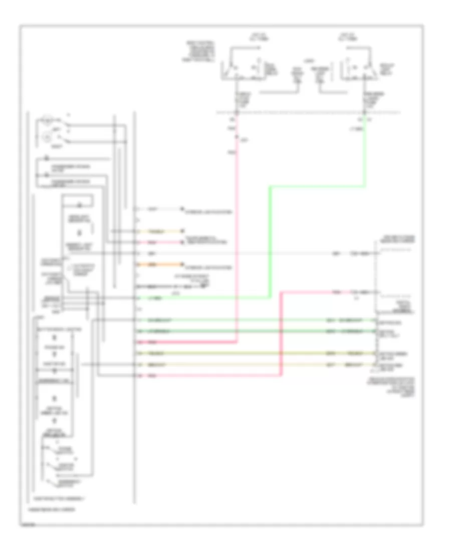
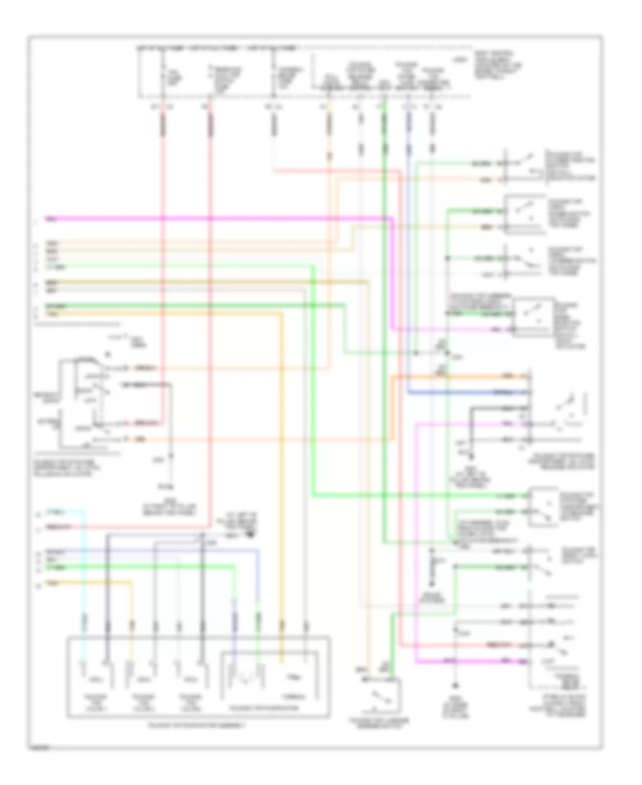
AIR CONDITIONING
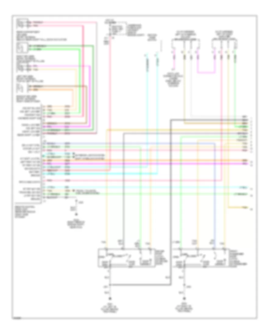
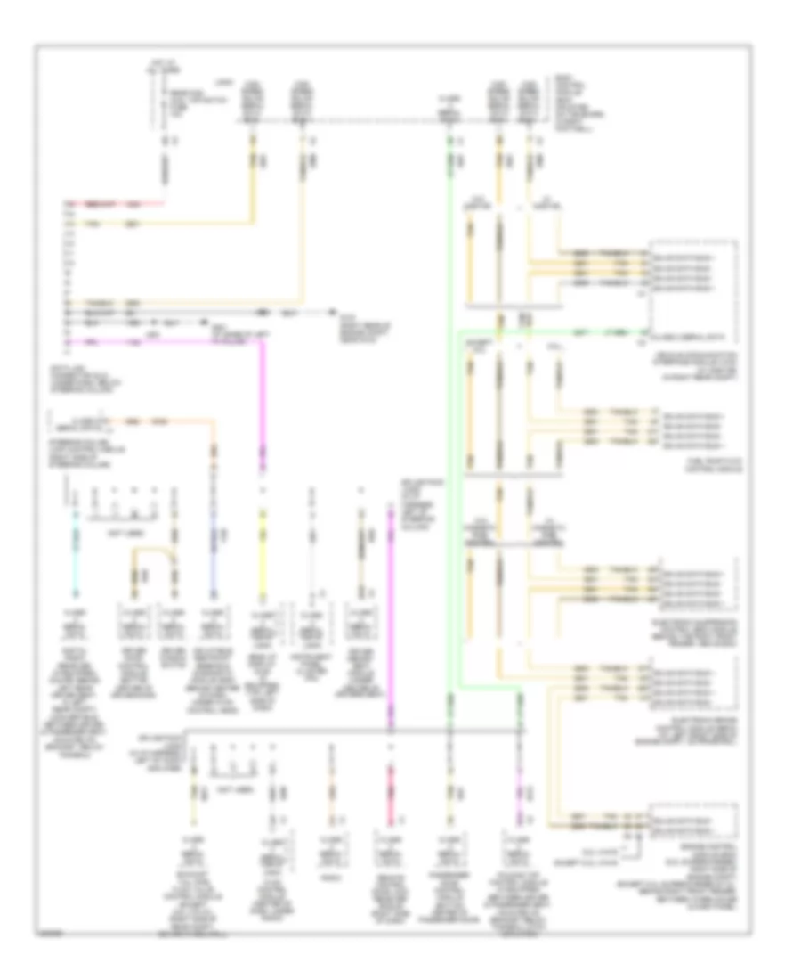
Automatic A/C Wiring Diagram (1 of 2) for Chevrolet Corvette 2009
 https://portal-diagnostov.com/license.html
Automotive Electricians Portal FZCO
Automotive Electricians Portal FZCO
https://portal-diagnostov.com/license.html
https://portal-diagnostov.com/license.html
Automotive Electricians Portal FZCO
Automotive Electricians Portal FZCO
List of elements for Automatic A/C Wiring Diagram (1 of 2) for Chevrolet Corvette 2009:
- A/c comp fuse 15 10a
- A/c comp relay 35
- A/c compressor clutch (right front of engine block)
- A/c off switch
- Bat
- Blower ctrl
- Blower speed switch
- Body control module (bcm) (mounted on toe board, in right footwell)
- Charge air coolant pump (right front of engine compt)
- Coolfan fuse 25 60a
- Defog rly ctrl
- Defogger system
- Defrost frost
- Defrost switch
- Dr ctrl a
- Dr ctrl b
- Drv htd st sig
- E1 x2
- E10
- F13
- F14
- G102 (on top of right frame rail, ground for sp102)
- G202 (at base of right)
- Gnd
- H13
- H14
- Hot at all times
- Hot w/ run/ crnk relay energized
- Hvac control module (center of dash, under radio)
- Hvac fuse 28 40a
- Hvac/ pwr snd fuse 10a
- Ign
- Ign 1 voltage
- Inclr pump/elsd fuse 32 30a (6.2l (vin r))
- Inclr pump/elsd relay
- Interior lights system
- Isrvm/ hvac fuse 10a
- J102
- J197
- J216
- J231
- Lamp ctrl
- Left air tempe- rature switch
- Light sens sig
- Logic
- Low ref
- Mirrors & shift interlock systems
- Mode ctrl
- Mode switch
- Mtr spd ctrl
- Off ctrl
- Pass htd st sig
- Pnk
- Powertrain ign 1 relay 44
- Recirc ctrl
- Recirculation switch
- Right air tempe- rature switch
- Seats system
- Sens sig
- Serial data
- Speed ctrl
- Sply voltage
- Sply voltage 4
- Sunload sig
- Tan
- Temp ctrl
- Temp ctrl sig
- Underhood fuse block (on right side of engine compt)
- X1 c10
- X4 d8
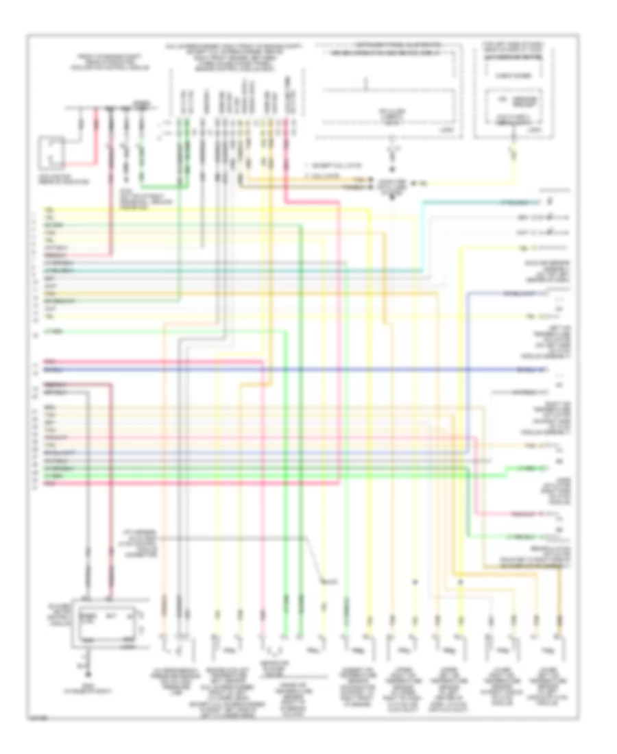
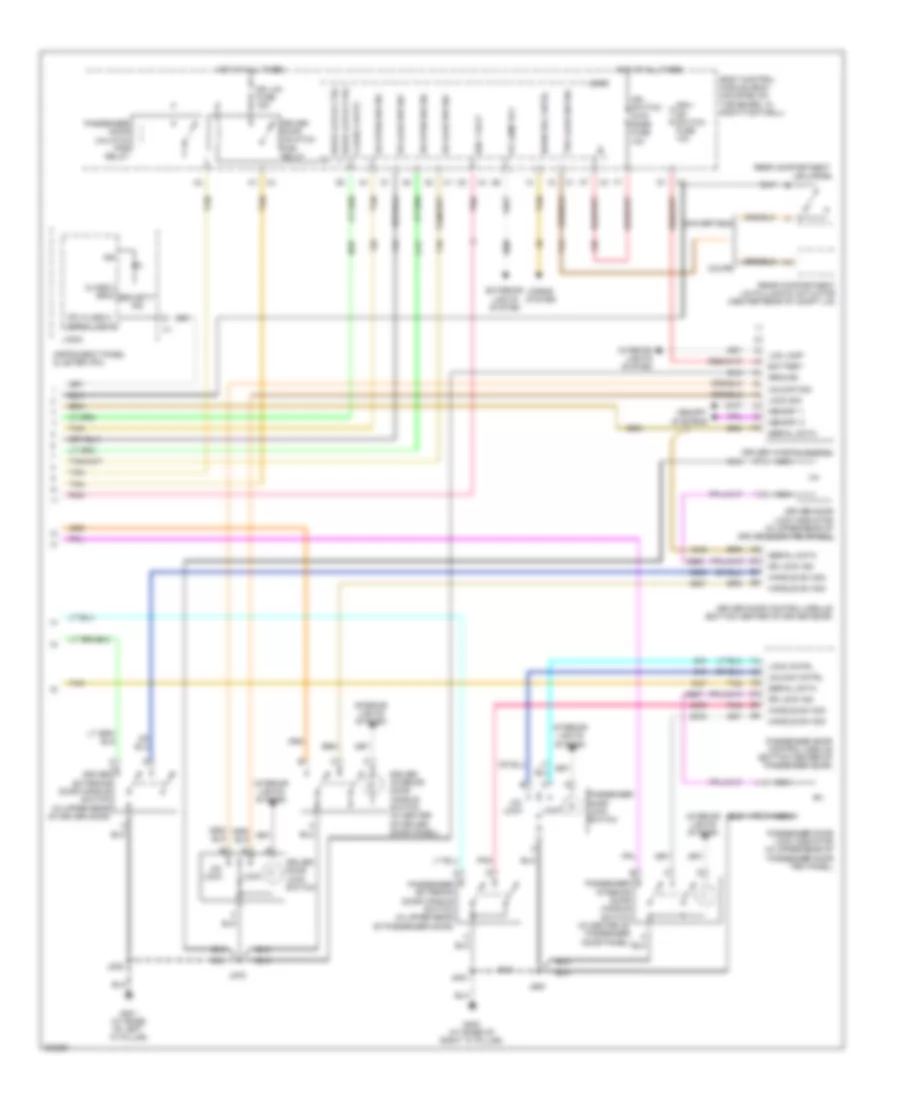
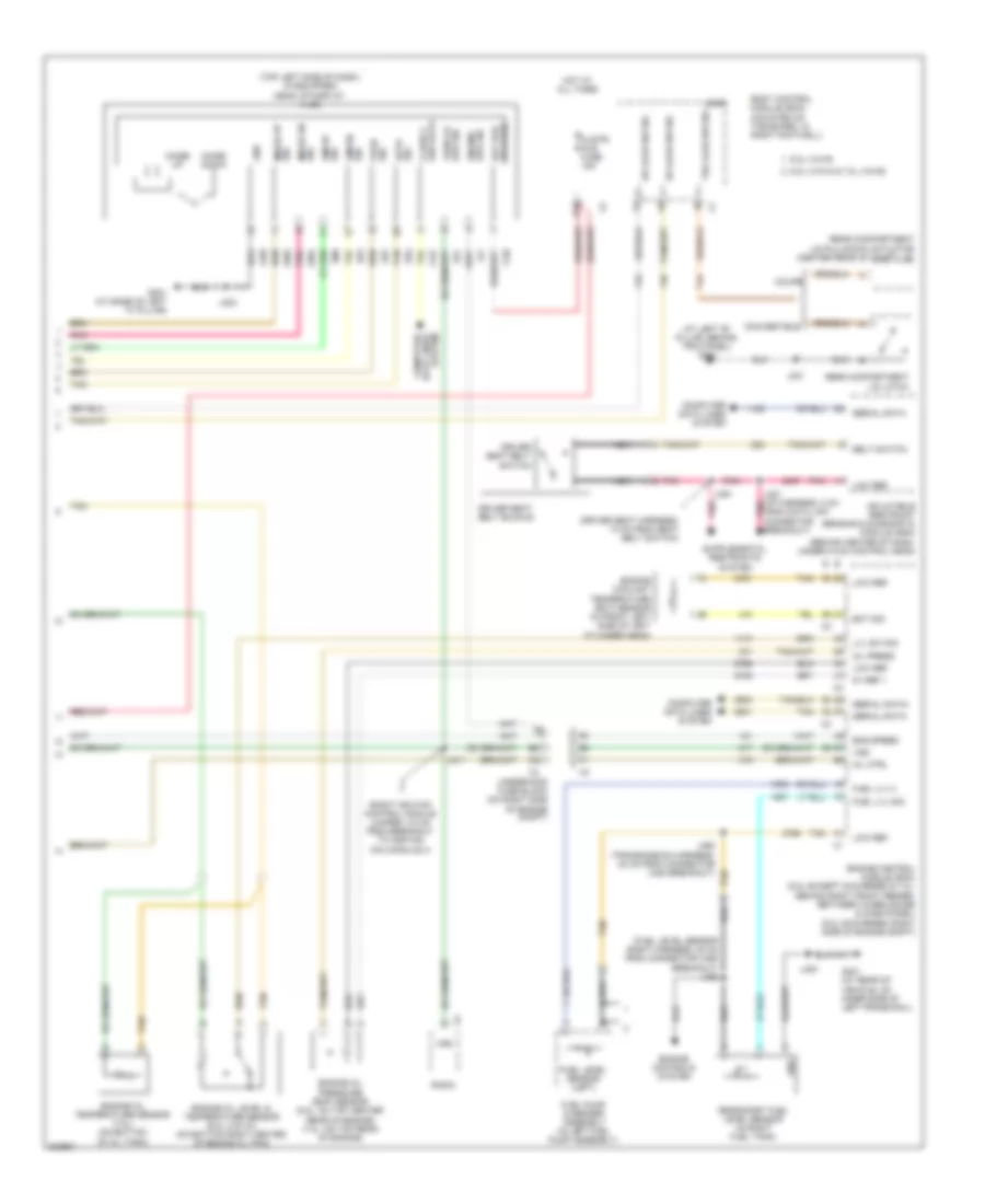
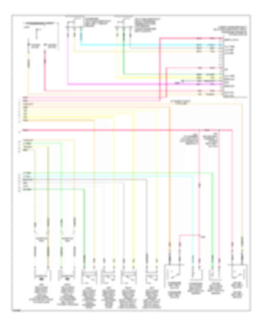
Automatic A/C Wiring Diagram (2 of 2) for Chevrolet Corvette 2009
List of elements for Automatic A/C Wiring Diagram (2 of 2) for Chevrolet Corvette 2009:
- (6.2l supercharged: right front of engine compt) (except 6.2l supercharged: behind right front fender, between wheelhouse & dash panel) engine control module (ecm)
- (front of engine compt, rear of radiator) cooling fan control module
- (i/p harness, 35 cm from hvac control module connector)
- (top left side of dash) head up display (hud)
- 5v ref
- 6.2l (vin r)
- A/c refrigerant pressure sensor (on a/c high pressure line)
- Ambient air temperature sensor (on radiator support, at right front of engine)
- Aspirator blower motor
- Bat
- Blower motor control module
- Check gages
- Computer data lines system
- Cooling fan (rear of radiator)
- Driver information center (dic) display
- Engine coolant temperature (ect) sensor (6.2l supercharged: front of left cylinder head) (except 6.2l supercharged: in front left side of left cylinder head)
- Except 6.2l (vin r)
- G102 (on top of right frame rail, ground for sp102)
- G202 (at base of right)
- Gnd
- Hud class 2 serial data
- Hud message center
- Ign
- Ignition 1
- Inside air temperature sensor (right of steering column)
- Instrument panel cluster (ipc)
- Ipc class 2 serial data
- J242
- Left air temperature actuator (on left side of hvac module assembly)
- Logic
- Low ref
- Lower left air temperature sensor (in left middle of hvac module)
- Lower right air temperature sensor (in right middle of hvac module)
- Message request
- Mode actuator (right side of hvac module)
- Nca
- Pnk
- Recirculation actuator (mounted to right side of blower motor assembly)
- Red
- Right air temperature actuator (on right side of hvac module assembly)
- Rly ctrl
- Rly ctrl coolant pumr
- Sens sig
- Serial data +
- Serial data -
- Speed ctrl
- Sunload sensor assembly (on top left center of dash)
- Tan
- Upper left air temperature sensor (in left center of dash, in hvac air flow duct)
- Upper right air temperature sensor (in upper right of dash, in hvac air flow duct)
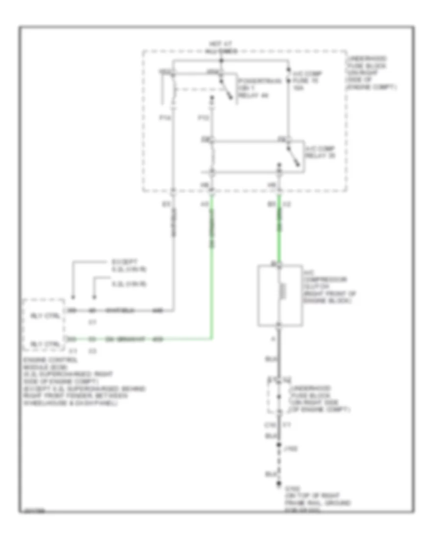
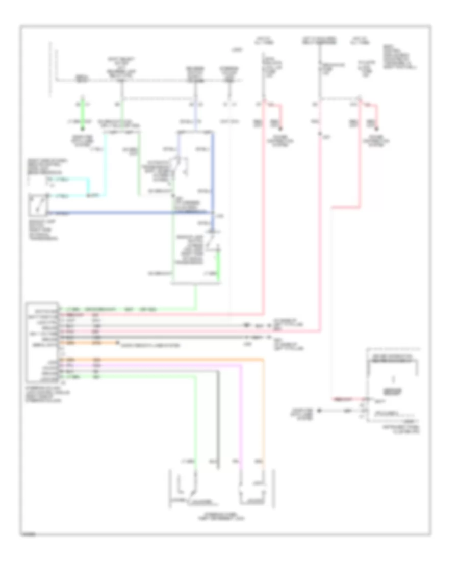
Compressor Wiring Diagram for Chevrolet Corvette 2009
List of elements for Compressor Wiring Diagram for Chevrolet Corvette 2009:
- 6.2l (vin r)
- A/c comp fuse 15 10a
- A/c comp relay 35
- A/c compressor clutch (right front of engine block)
- E1 x2
- Engine control module (ecm) (6.2l supercharged: right side of engine compt) (except 6.2l supercharged: behind right front fender, between wheelhouse & dash panel)
- Except 6.2l (vin r)
- F13
- F14
- G102 (on top of right frame rail, ground for sp102)
- H13
- H14
- Hot at all times
- J102
- Powertrain ign 1 relay 44
- Rly ctrl
- Underhood fuse block (on right side of engine compt)
- X1 c10
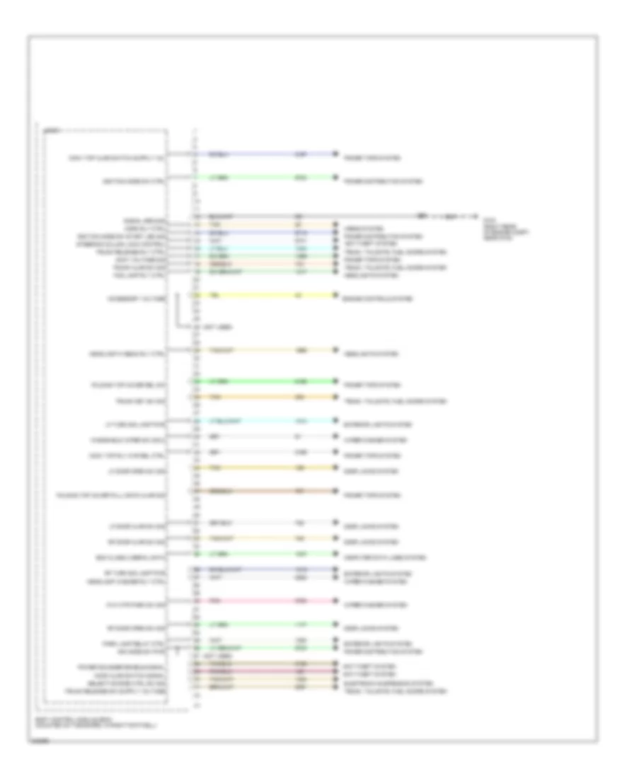
ANTI-LOCK BRAKES
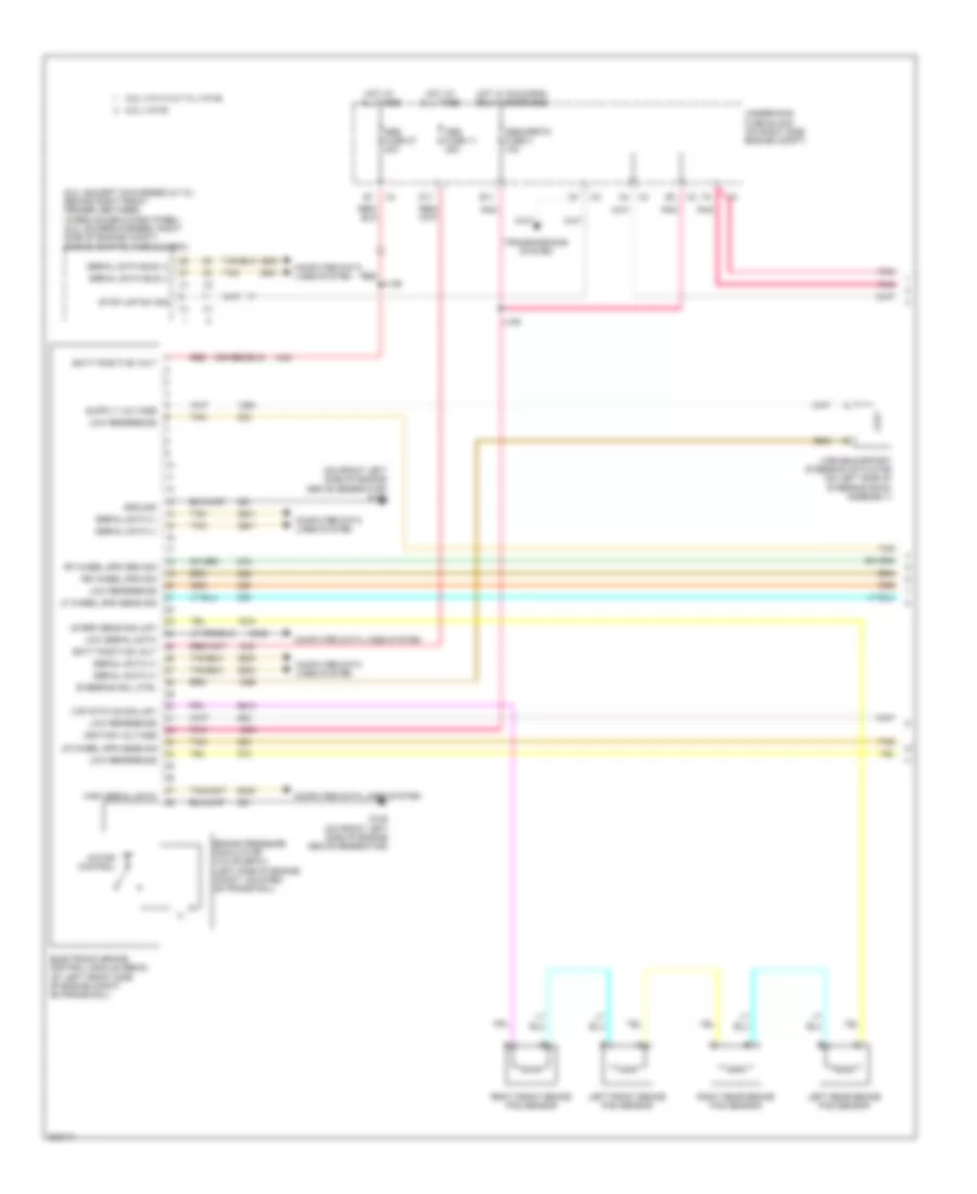
Anti-lock Brakes Wiring Diagram (1 of 2) for Chevrolet Corvette 2009
List of elements for Anti-lock Brakes Wiring Diagram (1 of 2) for Chevrolet Corvette 2009:
- (6.2l (except s/charged) & 7.0l: behind right front fender, between wheelhouse & dash panel) (6.2l (supercharger): right side of engine compt) engine control module (ecm)
- (on front left side of engine above generator) g105
- 6.2l (vin r)
- 6.2l (vin w) & 7.0l (vin e)
- Abs fuse 11 25a
- Abs fuse 27 40a
- Abs/mrrtd fuse 3 10a
- Batt positive volt
- Brake pressure modulator valve (bpmv) (left side of engine compt, mounted on frame rail)
- Computer data lines system
- D11
- E11
- Electronic brake control module (ebcm) (at left front side of engine compt, on frame rail)
- G105 (on front left side of engine above generator)
- Ground
- High serial data
- Hot at all times
- Hot w/ run/crnk relay energized
- Ignition voltage
- J139
- J195
- Left front brake pad sensor
- Left rear brake pad sensor
- Lf wheel spd sens sig
- Low reference
- Low serial data
- Lr brk sens sig (j57)
- Lr wheel spd sens sig
- Motor control
- Pnk
- Red
- Rf wheel spd sen sig
- Right front brake pad sensor
- Right rear brake pad sensor
- Rr wheel spd sig
- Serial data (+)
- Serial data (-)
- Serial data bus (+)
- Serial data bus (-)
- Steering sol ctrl
- Stop lmp sw sig
- Tan
- Transmissions system
- Underhood fuse block (on right side engine compt)
- Variable effort steering actuator (on left side of steering rack assembly)
- Vcp status sig (j57)
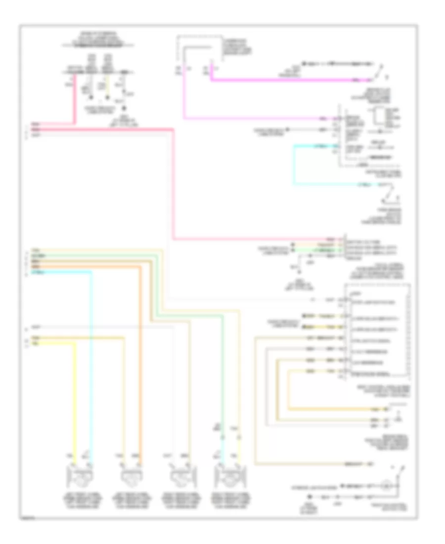
Anti-lock Brakes Wiring Diagram (2 of 2) for Chevrolet Corvette 2009
List of elements for Anti-lock Brakes Wiring Diagram (2 of 2) for Chevrolet Corvette 2009:
- (base of steering column, under dash) (w/ active brake control) steering angle sensor
- 5 volt reference
- Abs ind
- Body control module (bcm) (mounted on toe board, in right footwell)
- Brake fluid level switch (in master cylinder reservoir)
- Brake fluid lvl sens sig
- Brake ind
- Brake pedal position (bpp) sensor (mounted on brake pedal bracket)
- Can bus high serial data
- Can bus low serial data
- Class 2 serial data
- Computer data lines system
- Ctrl switch signal
- Driver info center (dic) display
- G101 (on left frame rail)
- G201 (at base of left "a" pillar)
- G202 (at base of right)
- Grd
- Ground
- Hi spd gmlan ser data +
- Hi spd gmlan ser data -
- Ignition voltage
- Instrument panel cluster (ipc)
- Interior lights system
- J101
- J200
- J246
- J275
- Left front wheel speed sensor (wss) (left front wheel hub assemblies)
- Left rear wheel speed sensor (wss) (left rear wheel hub assemblies)
- Logic
- Low reference
- Park brake switch (lower front of park brake handle)
- Pnk
- Position sw signal
- Prk brk sw sig
- Right front wheel speed sensor (wss) (right front wheel hub assemblies)
- Right rear wheel speed sensor (wss) (right rear wheel hub assemblies)
- Stop lamp switch sig
- Tan
- Traction control switch (tcs)
- Underhood fuse block (on right side engine compt)
- Yaw & lateral accelerometer sensor (w/ active brake control) (under hvac control head)
ANTI-THEFT
Forced Entry Wiring Diagram (1 of 2) for Chevrolet Corvette 2009
List of elements for Forced Entry Wiring Diagram (1 of 2) for Chevrolet Corvette 2009:
- (in i/p harness, left of audio amplifier) splice pack jx208
- (in i/p harness, left of steering column) splice pack jx205
- A/t shft lk ctrl
- Ajar
- Backup keyless entry antenna (right side of dash)
- Battery
- Closed
- D11
- Data link connector (dlc) (under dash, below steering column)
- Door ajar sw
- Door latch
- Door open sw
- Dr lk act ctrl
- Driver door latch (in rear of driver door)
- Dvr dr lk act
- Ecm/tcm/ easy key fuse 11 15a
- Exterior lights system
- Front passenger door latch (in rear of passenger door)
- G103 (right rear of engine compt, near g104)
- G301 (at left "b" pillar, behind trim panel)
- G302 (at right "b" pillar, behind trim panel)
- Ground
- Hot at all times
- Ign 1 volt
- Ign mod data
- Ignition mode switch
- J232
- J301
- J302
- K/e ant b-u sig
- K/e b-u low ref
- K/e left low ref
- K/e left sig
- K/e rear compt sig
- K/e right sig
- K/e rt low ref
- Left frnt int dr
- Left keyless entry antenna (top of left "b" pillar)
- Lf frt ext dr
- Open
- Pnk
- Rear compartment keyless entry antenna (below rear compt pull down actuator)
- Rear compt lo ref
- Remote control door lock receiver (rcdlr) (right side of dash)
- Rfa class 2 data
- Right keyless entry antenna (top of right "b" pillar)
- Rt frnt int dr
- Rt frt ext dr
- Shift interlock system
- Tan
- Trunk rel sw sig
- Trunk, tailgate, fuel doors system
- Underhood fuse block (on right side of engine compt)
- X2 a
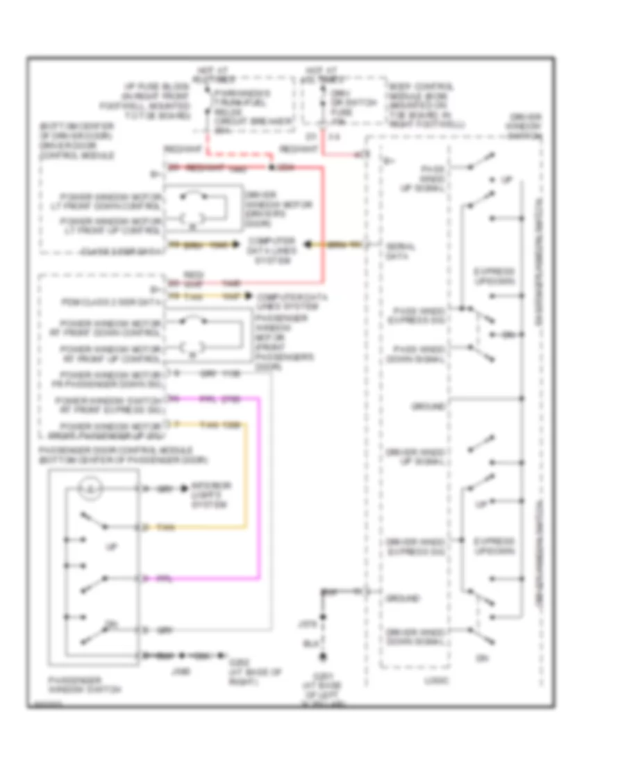
Forced Entry Wiring Diagram (2 of 2) for Chevrolet Corvette 2009
List of elements for Forced Entry Wiring Diagram (2 of 2) for Chevrolet Corvette 2009:
- A1 x3
- Battery
- Body control module (bcm) (mounted on toe board, in right footwell)
- Class 2 (bcm)
- Class 2 data
- Convertible
- Coupe
- Door latch ctrl
- Dr ajar sw sig
- Dr lck fuse 15a
- Dr lock ind
- Dr open sw sig
- Driv dr switch fuse 10a
- Driver door control module (bottom center of driver door)
- Driver door lock indicator (in upper rear of driver door trim panel)
- Driver door lock switch
- Driver door unlatch pcb relay
- Driver exterior door handle switch (in upper rear of driver door)
- Driver interior door handle switch (in center of driver door panel)
- Driver window switch
- Exterior lights system
- G201 (at base of left "a" pillar)
- G202 (at base of right "a" pillar)
- Ground
- Handle sw sig
- Horn rel cntrl
- Horns system
- Hot at all times
- Ign
- Ign 1 volt
- Ign switch/ intr snsr fuse 10a
- Instrument panel cluster (ipc)
- Interior lights system
- Ipc class 2 serial data
- J539
- J579
- J640
- J680
- Lcd lamp
- Lock
- Lock cntrl
- Lock sig
- Logic
- Memory 1
- Memory 2
- Memory systems
- Nca
- Passenger door control module (bottom center of passenger door)
- Passenger door lock indicator (in upper rear of passenger door trim panel)
- Passenger door lock switch
- Passenger door unlatch pcb relay
- Passenger exterior door handle switch (in upper rear of passenger door)
- Passenger interior door handle switch (in center of passenger door panel)
- Pk lamp rly
- Pnk
- Rear compartment lid latch
- Rear compartment lid pulldown actuator (center rear of compt lid)
- Security ind
- Serial data
- Tan
- Trk ajar sw sig
- Un- lock
- Unlock cntrl
- Unlock sig
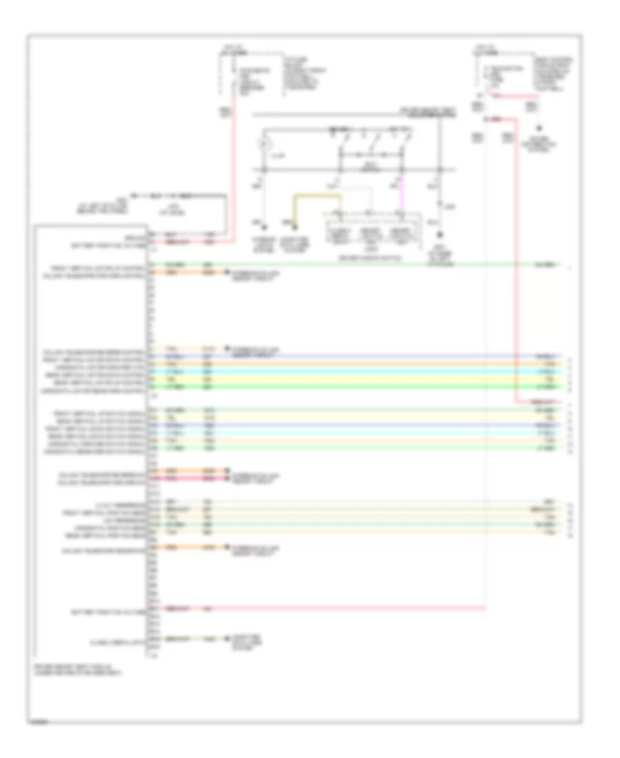
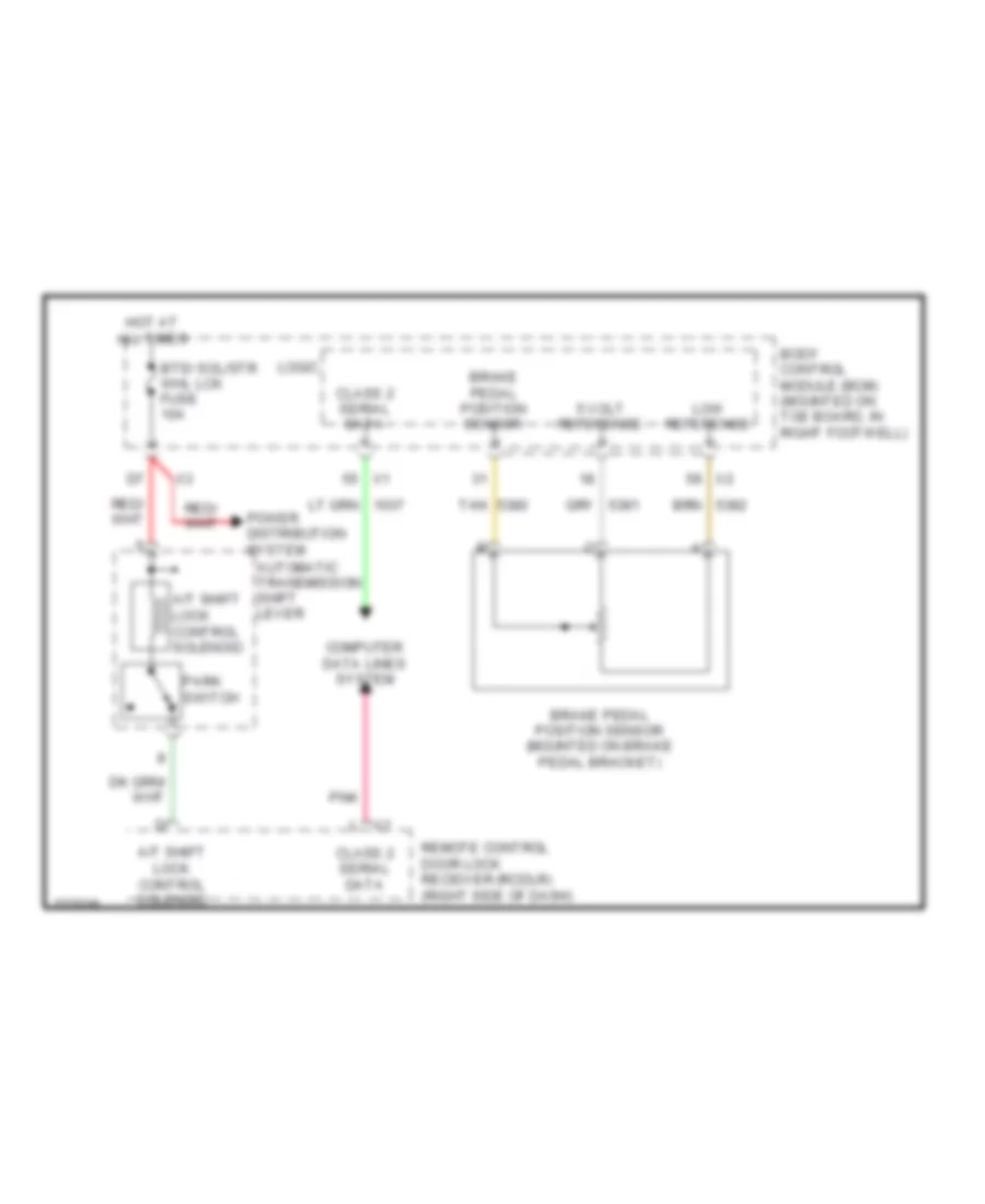
Steering Lock Wiring Diagram for Chevrolet Corvette 2009
List of elements for Steering Lock Wiring Diagram for Chevrolet Corvette 2009:
- (at base of left "a" pillar) g201
- (or 1932)
- (right side of dash) remote control door lock receiver (rcdlr)
- A lock sig
- A/t
- Automatic transmission shift lever (closed in park)
- B ground
- Backup lamp switch (right side of manual transmission)
- Backup lamp switch (w/rear fog lamp) (right side of manual transmission)
- Batt
- Batt positive
- Body control module (bcm) (mounted on toe board, in right footwell)
- Btsi sol/str whl lck fuse 10a
- C unlock
- Clstr/ hud fuse 15a
- Computer data lines system
- D lock
- D10
- Driver information center (dic) display
- G201 (at base of left "a" pillar)
- Ground
- Hot at all times
- Hot w/ run crnk relay energized
- Ign 1 voltage
- Instrument panel cluster (ipc)
- Ipc class 2
- Isrvm/hvac fuse 10a
- J100
- J218
- J231
- J251 (i/p harness, 6.5 cm from x150 breakout)
- J303
- J320
- Lock
- Lock ctrl
- Locked
- Logic
- M/t
- Message request
- Pnk
- Power distribution system
- Serial data
- Shift select sw sig (a/t) reverse lamp relay ctrl (m/t)
- Steering column lock control module (right side of steering column)
- Steering column lock ctrl
- Steering wheel theft deterrent lock
- Switch sig
- Unlock
- Unlocked
BODY CONTROL MODULES
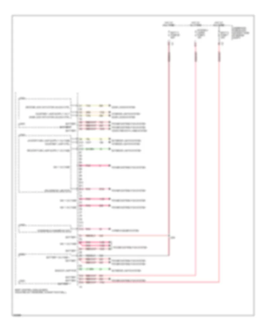
Body Control Modules Wiring Diagram (1 of 4) for Chevrolet Corvette 2009
List of elements for Body Control Modules Wiring Diagram (1 of 4) for Chevrolet Corvette 2009:
- (not used)
- Accessory voltage
- Accy voltage sig
- Anti-theft system
- Bcm class 2 serial data
- Body control module (bcm) (mounted on toe board, in right footwell)
- Computer data lines system
- Conv top rly cvr rel ctrl
- Door locks system
- Electronic suspension system
- Engine controls system
- Exterior lights system
- Fog lamp rly ctrl
- Folding top cover pull down ajar sig
- Folding top cover rel sw
- G103 (right rear of engine compt, near g104)
- Headlamp hi beam rly ctrl
- Headlamp washer rly ctrl
- Headlights system
- Hood ajar switch signal
- Horn rly ctrl
- Horns system
- Ign mode sw pwr
- Ignition mode sw ctrl
- Ignition mode sw start led sig
- J232
- Lf door ajar sw sig
- Lf door open sw sig
- Lf turn sig lamp pwr
- Logic
- Park lamp relay ctrl
- Pnk
- Power distribution system
- Power sounder enable signal
- Power tops system
- Rf door ajar sw sig
- Rf door open sw sig
- Rf turn sig lamp pwr
- Selective ride ctrl sw sig
- Signal ground
- Steering column lock control
- Tan
- Trunk ajar sw sig
- Trunk key sw sig
- Trunk release rly ctrl
- Trunk, tailgate, fuel doors system
- W/w mtr park sw sig
- Windshield wiper sw sig 2
- Wiper/washer system
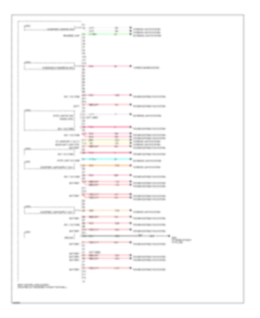
Body Control Modules Wiring Diagram (2 of 4) for Chevrolet Corvette 2009
List of elements for Body Control Modules Wiring Diagram (2 of 4) for Chevrolet Corvette 2009:
- A10
- A11
- A12
- B10
- B11
- B12
- Backup lamp pwr
- Batt 3 fuse 26 60a
- Batt 5 fuse 7 30a
- Battery
- Battery voltage +
- Body control module (bcm) (mounted on toe board, in right footwell)
- C10
- C11
- C12
- Computer data lines system
- Courtesy lamp ctrl
- D10
- D11
- D12
- Door lock actuator unlock ctrl
- Door locks system
- Drvr dr lock actuator unlock ctrl
- Exterior lights system
- Hot at all times
- Ign 1 voltage
- Ign mode sw led pwr
- Interior lights system
- J208
- Logic
- Pnk
- Power distribution system
- Stop/b/u/ lamps fuse 5 15a
- Tan
- Underhood fuse block (on right side of engine compt)
- Windshield washer sw sig
- Wiper/washer system
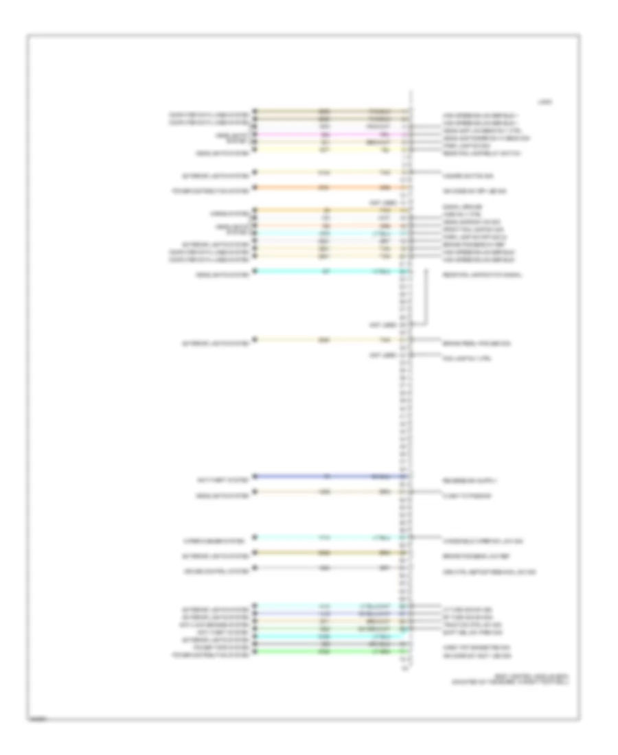
Body Control Modules Wiring Diagram (3 of 4) for Chevrolet Corvette 2009
List of elements for Body Control Modules Wiring Diagram (3 of 4) for Chevrolet Corvette 2009:
- (not used)
- A10
- A11
- A12
- B10
- B11
- B12
- Backlight lamp ctrl
- Batt
- Battery
- Body control module (bcm) (mounted on toe board, in right footwell)
- C10
- C11
- C12
- Courtesy lamp sw sig
- D10
- D11
- D12
- E10
- E11
- E12
- Exterior lights system
- F10
- F11
- F12
- G202 (at base of right "a" pillar)
- Ground
- I/p lamps sply volt 2
- Ign 1 voltage
- Inside logic
- Interior lights system
- J216
- Logic
- Pnk
- Power distribution system
- Reverse lamp
- Stop lamp sw sig
- Stop lamp voltage
- Windshield washer sw sig
- Wiper/washer system
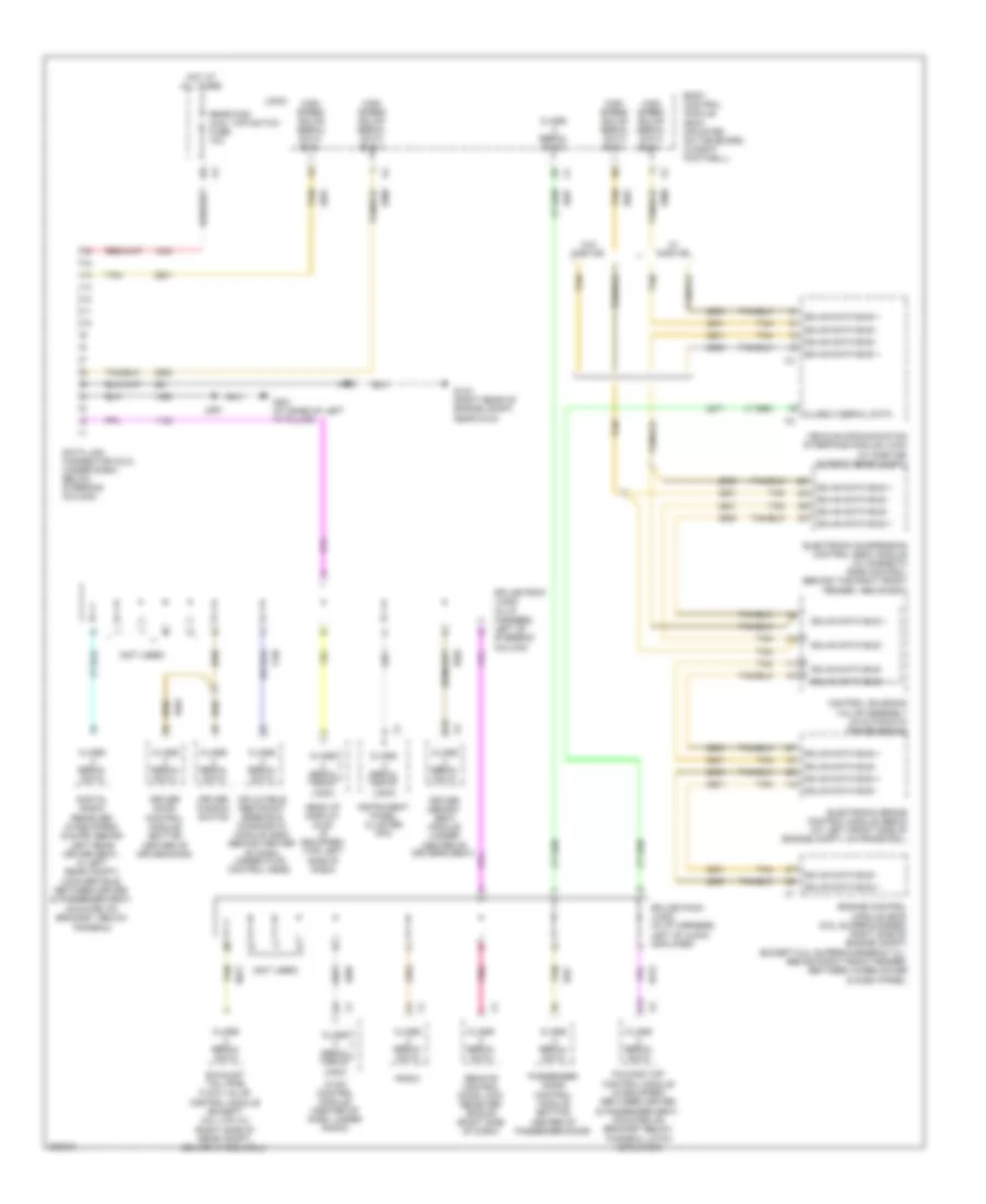
Body Control Modules Wiring Diagram (4 of 4) for Chevrolet Corvette 2009
List of elements for Body Control Modules Wiring Diagram (4 of 4) for Chevrolet Corvette 2009:
- (not used)
- Anti-lock brakes system
- Anti-theft system
- Body control module (bcm) (mounted on toe board, in right footwell)
- Brake pedal pos sen sig
- Brake pos sens 5v ref
- Brake pos sens low ref
- Computer data lines system
- Crs ctrl set/cst/res/accl sw sig
- Cruise control system
- Exterior lights system
- Flash to pass sig
- Fog lamp rly ctrl
- Front fog lamp sw sig
- Hard top connected sig
- Hazard switch sig
- Headlamp dimmer sw hi beam sig
- Headlamp low beam rly ctrl
- Headlamps sw on sig
- Headlights system
- High speed gmlan ser bus +
- High speed gmlan ser bus -
- Horn rly ctrl
- Horns system
- Ign mode sw accy led sig
- Ign mode sw off led sig
- Lf turn sig sw sig
- Logic
- Park lamp sw off sig (2)
- Park lamp sw sig
- Power distribution system
- Power tops system
- Rear fog lamp relay switch
- Rear fog lamp switch signal
- Rf turn sig sw sig
- Shift sel sw park sig
- Signal ground
- Tan
- Traction ctrl sw sig
- Windshield wiper sw low sig
- Wiper/washer system
COMPUTER DATA LINES
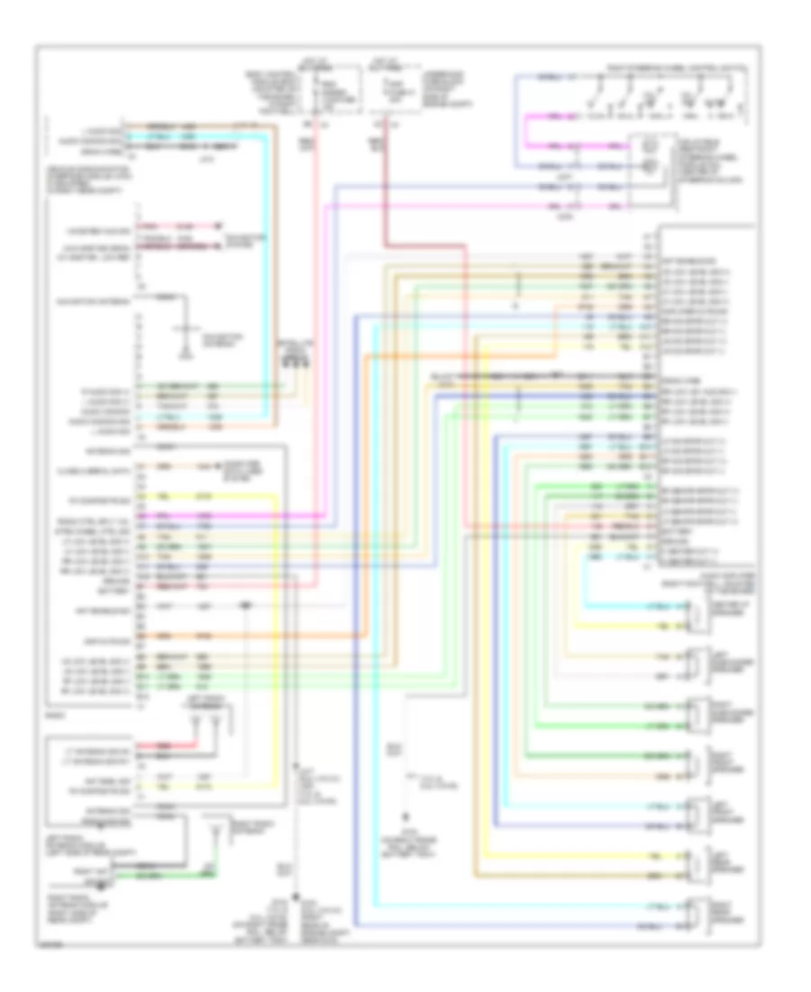
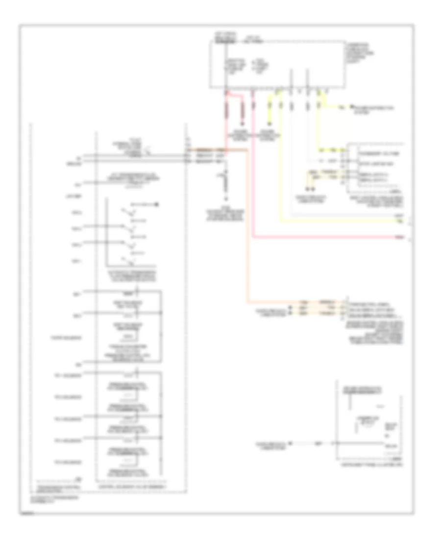
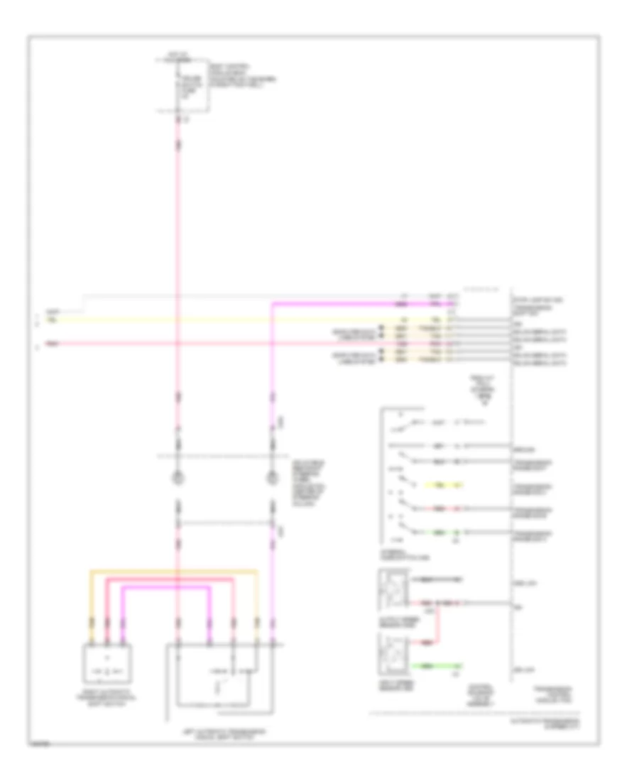
Computer Data Lines Wiring Diagram, A/T for Chevrolet Corvette 2009
List of elements for Computer Data Lines Wiring Diagram, A/T for Chevrolet Corvette 2009:
- (not used)
- B15
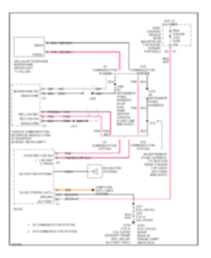
- Body control module (bcm) (mounted on toe board, in right footwell)
- Center of driver's seat)
- Class 2 serial data
- Class serial data
- Control solenoid valve assembly (in automatic transmission)
- D14
- Data link connector (dlc) (under dash, below steering column)
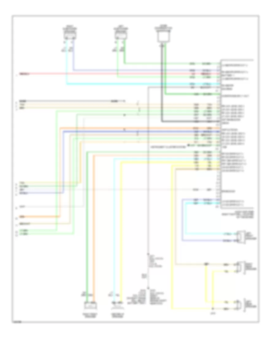
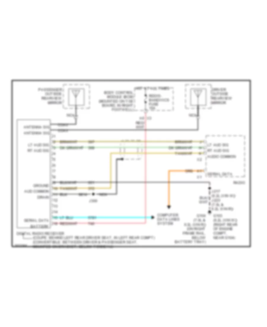
- Digital radio receiver (if equipped) (coupe: behind left rear driver seat, in left rear compt) (convertible: between driver & passenger seat, mounted on bracket, below tonneau)
- Driver door control module (bottom center of driver door)
- Driver memory seat module (under
- Driver window switch
- Electronic brake control module (ebcm) (at left front side of engine compt, on frame rail)
- Electronic suspension control (esc) module (w/ magnetic ride control) (behind the right front fender, above ecm)
- Engine control module (ecm) (6.2l supercharged: right side of engine compt) (except 6.2l supercharged & 7.2l: behind right front fender, between wheelhouse & dash panel)
- Exhaust tail pipe flow valve control module (except 6.2l (vin w)) (right side of rear compt, behind wheelwell)
- Folding top control module (if equipped) (between driver & passenger seat, mounted on bracket below tonneau latch actuator)
- G103 (right rear of engine compt, near g104)
- G201 (at base of left "a" pillar)
- Gmlan data bus +
- Gmlan data bus -
- Head up display (hud) (if equipped) (top left side of dash)
- High speed gmlan serial data bus +
- High speed gmlan serial data bus -
- Hot at all times
- Hvac control module (center of dash, under radio)
- Inflatable restraint sensing & diagnostic module (sdm) (behind center of dash, under hvac control head)
- Instrument panel cluster (ipc)
- J200
- J232
- Logic
- Passenger door control module (bottom center of passenger door)
- Pnk
- Radio
- Rear fog/ aldl top swtch fuse 10a
- Remote control door lock receiver (rcdlr) (right side of dash)
- Splice pack jx205 (in i/p harness, left of steering column)
- Splice pack jx208 (in i/p harness, left of audio amplifier)
- Tan
- Vehicle communication interface module (vcim) (w/ onstar) (in right rear compt)
- W/ onstar
- W/o onstar
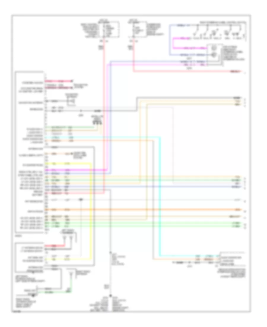
Computer Data Lines Wiring Diagram, M/T for Chevrolet Corvette 2009
List of elements for Computer Data Lines Wiring Diagram, M/T for Chevrolet Corvette 2009:
- (not used)
- 6.2l
- 6.2l (vin r)
- B14
- B15
- Body control module (bcm) (mounted on toe board, in right footwell)
- Center of drivers seat)
- Class 2
- Class 2 serial data
- Class serial data
- Data link connector (dlc) (under dash, below steering column)
- Digital radio receiver (if equipped) (coupe: behind left rear driver seat, in left rear compt) (convertible: between driver & passenger seat, mounted on bracket, below tonneau)
- Driver door control module (bottom center of driver door)
- Driver memory seat module (under
- Driver window switch
- Electronic brake control module (ebcm) (at left front side of engine compt, on frame rail)
- Electronic suspension control (esc) module (behind the right front fender, above ecm)
- Engine control module (ecm) (6.2l supercharged: right side of engine compt) (except 6.2l supercharged & 7.2l: behind right front fender, between wheelhouse & dash panel)
- Except 6.2l
- Except 6.2l (vin r)
- Exhaust tail pipe flow valve control module (except 6.2l (vin w)) (right side of rear compt, behind wheelwell)
- Folding top control module (if equipped) (between driver & passenger seat, mounted on bracket below tonneau latch actuator)
- Fuel pump flow control module
- G103 (right rear of engine compt, near g104)
- G201 (at base of left "a" pillar)
- Gmlan data bus +
- Gmlan data bus -
- Head up display (hud) (if equipped) (top left side of dash)
- High speed gmlan serial data bus +
- High speed gmlan serial data bus -
- Hot at all times
- Hvac control module (center of dash, under radio)
- Inflatable restraint sensing & diagnostic module (sdm) (behind center of dash, under hvac control head)
- Instrument panel cluster (ipc)
- J200
- J232
- Logic
- Passenger door control module (bottom center of passenger door)
- Pnk
- Radio
- Rear fog/ aldl top swtch fuse 10a
- Remote control door lock receiver (rcdlr) (right side of dash)
- Serial data x1
- Splice pack jx205 (in i/p harness, left of steering column)
- Splice pack jx208 (in i/p harness, left of audio amplifier)
- Steering column lock control module (right side of steering column)
- Tan
- Vehicle communication interface module (vcim) (w/ onstar) (in right rear compt)
- W/ magnetic ride control
- W/ onstar
- W/o magnetic ride control
- W/o onstar
COOLING FAN
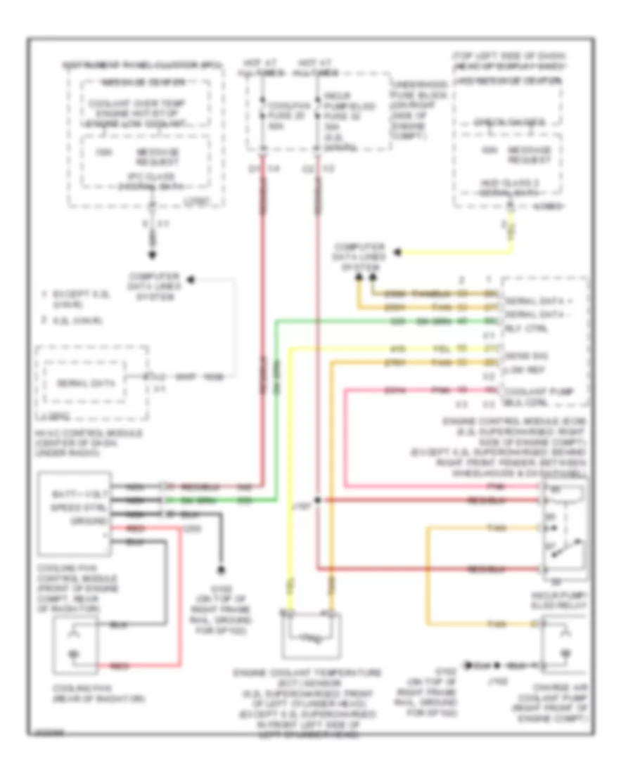
Cooling Fan Wiring Diagram for Chevrolet Corvette 2009
List of elements for Cooling Fan Wiring Diagram for Chevrolet Corvette 2009:
- (top left side of dash) head up display (hud)
- 6.2l (vin r)
- Batt+ volt
- Charge air coolant pump (right front of engine compt)
- Check gauges
- Computer data lines system
- Coolant over temp engine hot/stop engine low coolant
- Coolant pump rly ctrl
- Coolfan fuse 25 60a
- Cooling fan (rear of radiator)
- Cooling fan control module (front of engine compt, rear of radiator)
- Engine control module (ecm) (6.2l supercharged: right side of engine compt) (except 6.2l supercharged: behind right front fender, between wheelhouse & dash panel)
- Engine coolant temperature (ect) sensor (6.2l supercharged: front of left cylinder head) (except 6.2l supercharged: in front left side of left cylinder head)
- Except 6.2l (vin r)
- G102 (on top of right frame rail, ground for sp102)
- Ground
- Hot at all times
- Hud class 2 serial data
- Hud message center
- Hvac control module (center of dash, under radio)
- Ign
- Inclr pump/ elsd relay
- Inclr pump/elsd fuse 32 30a (6.2l (vin r))
- Instrument panel cluster (ipc)
- Ipc class 2 serial data
- J102
- J197
- Logic
- Low ref
- Message center
- Message request
- Nca
- Pnk
- Red
- Rly ctrl
- Sens sig
- Serial data
- Serial data +
- Serial data -
- Speed strl
- Tan
- Underhood fuse block (on right side of engine compt)
- X2 c2
CRUISE CONTROL
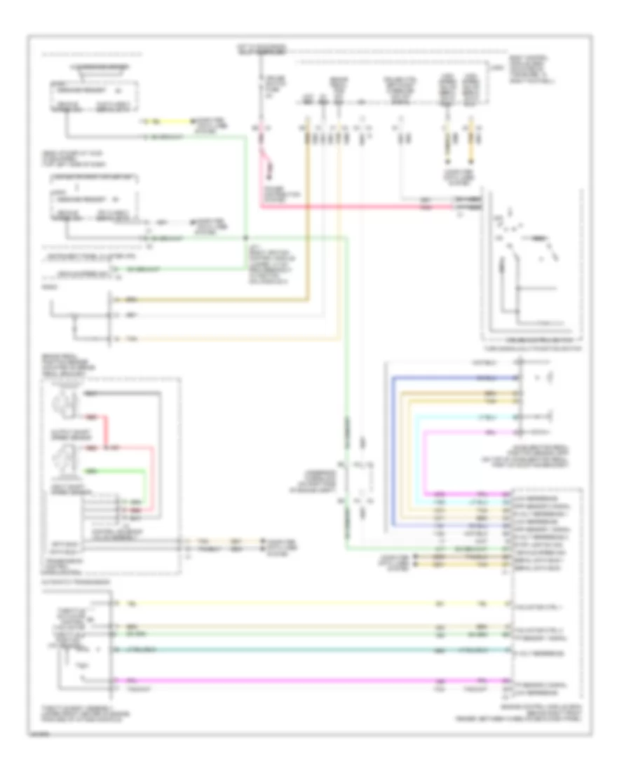
Cruise Control Wiring Diagram, A/T for Chevrolet Corvette 2009
List of elements for Cruise Control Wiring Diagram, A/T for Chevrolet Corvette 2009:
- 5 volt reference
- 5-volt reference 1
- 5-volt reference 2
- 5v ref
- Accelerator pedal position sensor (app) (on top of accelerator pedal, part of mounting bracket)
- App sensor 1 signal
- App sensor 2 signal
- Automatic transmission
- Body control module (bcm) (mounted on toe board, in right footwell)
- Brake pedal pos sw sig
- Brake pedal position sensor (mounted on brake pedal bracket)
- C4 x4
- Computer
- Computer data lines system
- Control (tac) motor
- Control solenoid valve assembly
- Cruise control switch
- Cruise ctrl set/coast & resume/ acc sw signal
- Cruise switch fuse 2a
- Data bus +
- Data bus -
- Data lines
- Driver information center
- E8 x4
- Engine control module (ecm) (behind right front fender, between wheelhouse & dash panel)
- Head up display (hud) (if equipped) (top left side of dash)
- High speed gmlan serial data bus +
- High speed gmlan serial data bus -
- Hot w/ run/crank relay energized
- Hud class 2 serial data
- Hud message center
- Input shaft speed sensor
- Instrument panel cluster (ipc)
- Ipc class 2 serial data
- J211 (right ignition control module jumper, 4.0 cm from breakout to ignition coil/module 4)
- J421
- Logic
- Low ref
- Low reference
- Message request
- Nca
- Off
- Output shaft speed sensor
- Pnk
- Power distribution system
- Radio
- Red
- Res+
- Serial data bus +
- Serial data bus -
- Set-
- Stop lamp sw sig
- System
- Tac motor ctrl 1
- Tac motor ctrl 2
- Tan
- Throttle actuator m
- Throttle body assembly (upper front center of engine, forward of intake manifold)
- Throttle position (tp) sensor
- Tp sensor 1 signal
- Tp sensor 2 signal
- Transmission control module (tcm)
- Turn signal/multi-function switch
- Underhood fuse block (on right side of engine compt)
- Vehicle speed sig
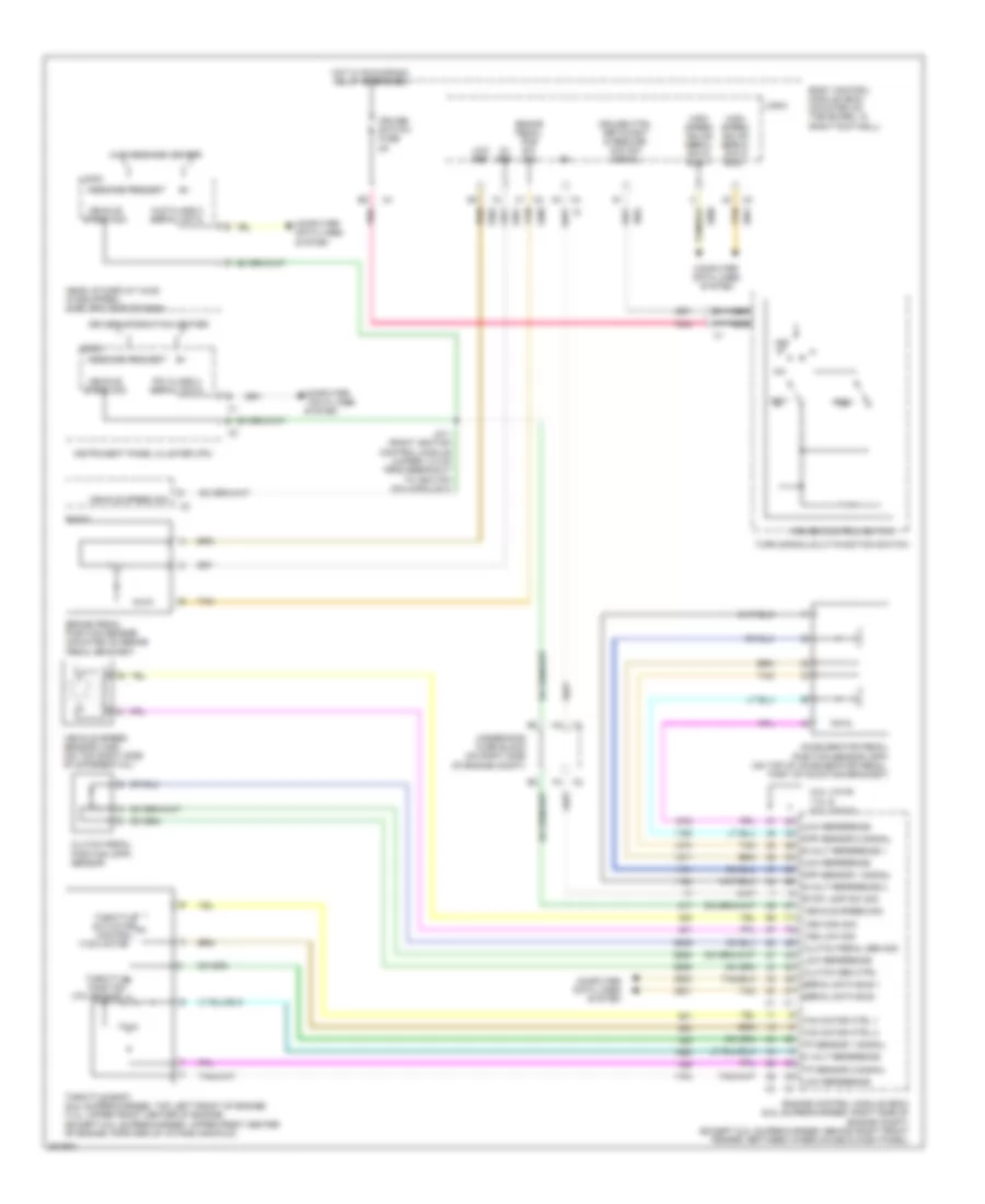
Cruise Control Wiring Diagram, M/T for Chevrolet Corvette 2009
List of elements for Cruise Control Wiring Diagram, M/T for Chevrolet Corvette 2009:
- (tac) motor
- (tp) sensor
- 5 volt reference
- 5-volt reference 1
- 5-volt reference 2
- 5v ref
- 6.2l (vin r)
- 7.0l & 6.2l (vin w)
- Accelerator pedal position sensor (app) (on top of accelerator pedal, part of mounting bracket)
- App sensor 1 signal
- App sensor 2 signal
- Body control module (bcm) (mounted on toe board, in right footwell)
- Brake pedal pos sw sig
- Brake pedal position sensor (mounted on brake pedal bracket)
- C4 x4
- Clutch pedal position (cpp) sensor
- Clutch pedal sen sig
- Clutch sen ctrl
- Computer
- Computer data lines system
- Control
- Cruise control switch
- Cruise ctrl set/coast & resume/ acc sw signal
- Cruise switch fuse 2a
- Data lines
- Driver information center
- Engine control module (ecm) (6.2l supercharged: right side of engine compt) (except 6.2l supercharged: behind right front fender, between wheelhouse & dash panel)
- Head up display (hud) (if equipped) (top left side of dash)
- High speed gmlan serial data bus +
- High speed gmlan serial data bus -
- Hot w/ run/crank relay energized
- Hud class 2 serial data
- Hud message center
- Instrument panel cluster (ipc)
- Ipc class 2 serial data
- J211 (right ignition control module jumper, 4.0 cm from breakout to ignition coil/module 4)
- Logic
- Low ref
- Low reference
- Message request
- Nca
- Off
- Pnk
- Radio
- Res+
- Serial data bus +
- Serial data bus -
- Set-
- Stop lamp sw sig
- System
- Tac motor ctrl 1
- Tac motor ctrl 2
- Tan
- Throttle actuator
- Throttle body (6.2l supercharged: top left front of engine) (7.0l: upper front center of engine) (except 6.2l supercharged: upper front center of engine, forward of intake manifold)
- Throttle position
- Tp sensor 1 signal
- Tp sensor 2 signal
- Turn signal/multi-function switch
- Underhood fuse block (on right side of engine compt)
- Vehicle speed sensor (vss) (on top right side of differential)
- Vehicle speed sig
- Vss high sig
- Vss low sig
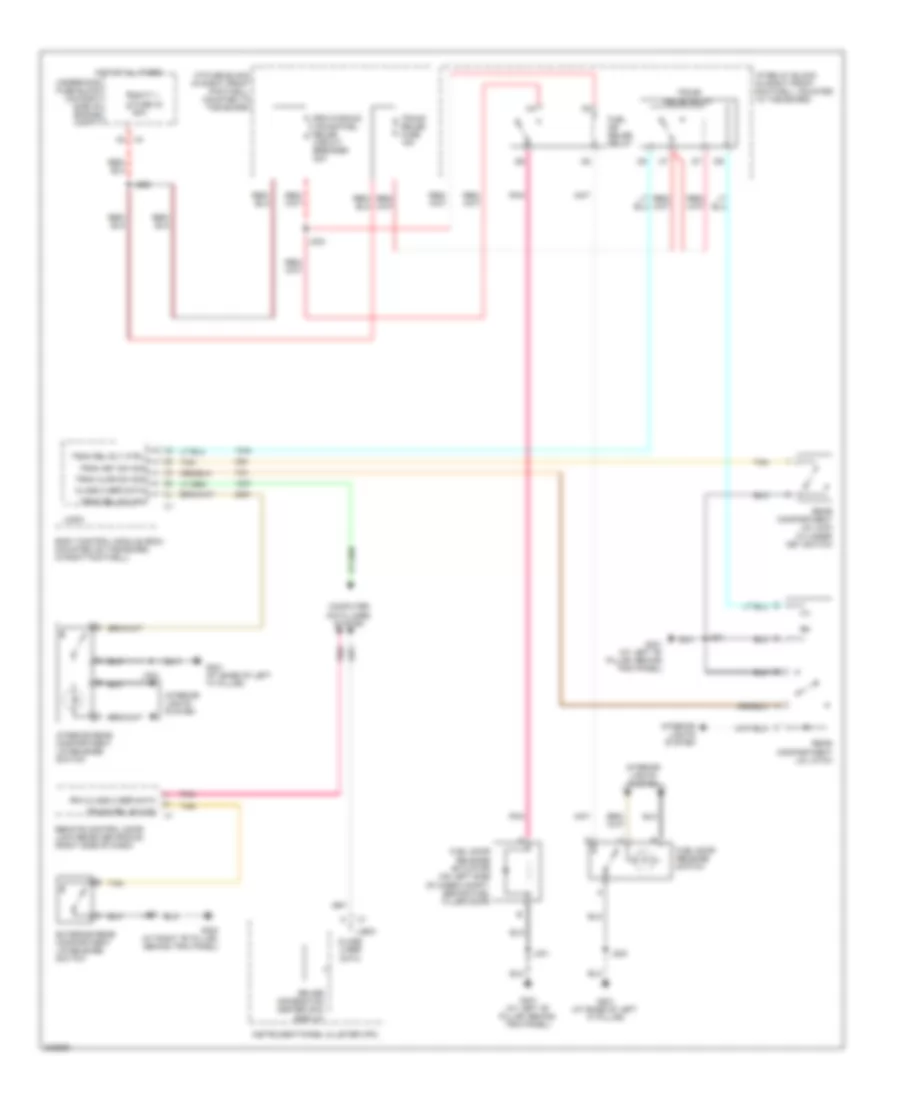
DEFOGGERS
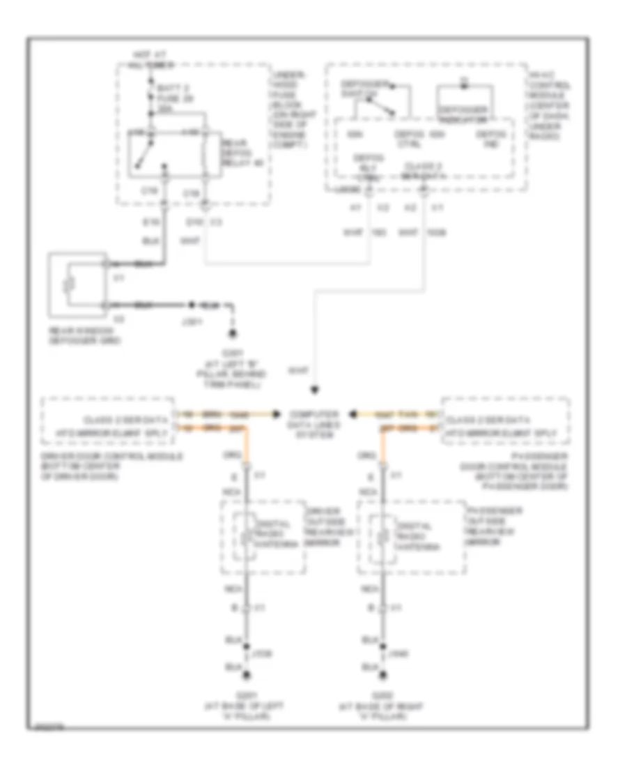
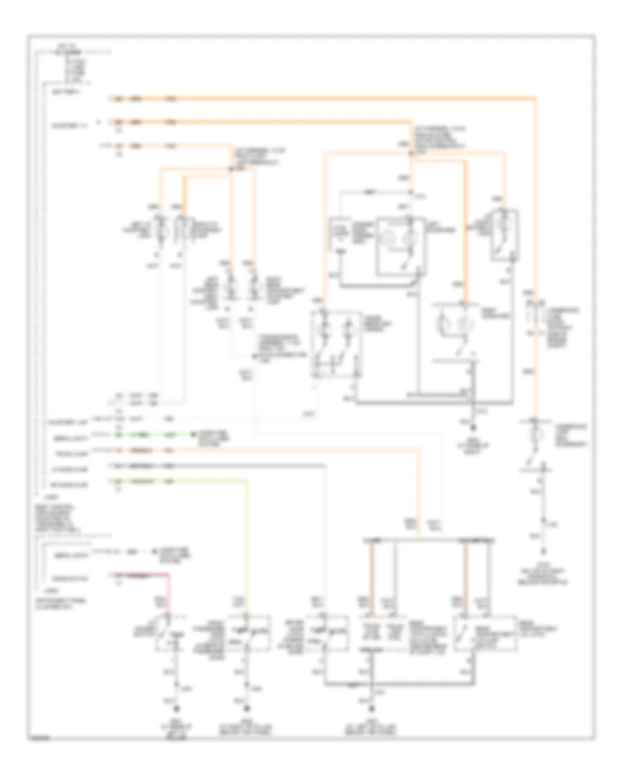
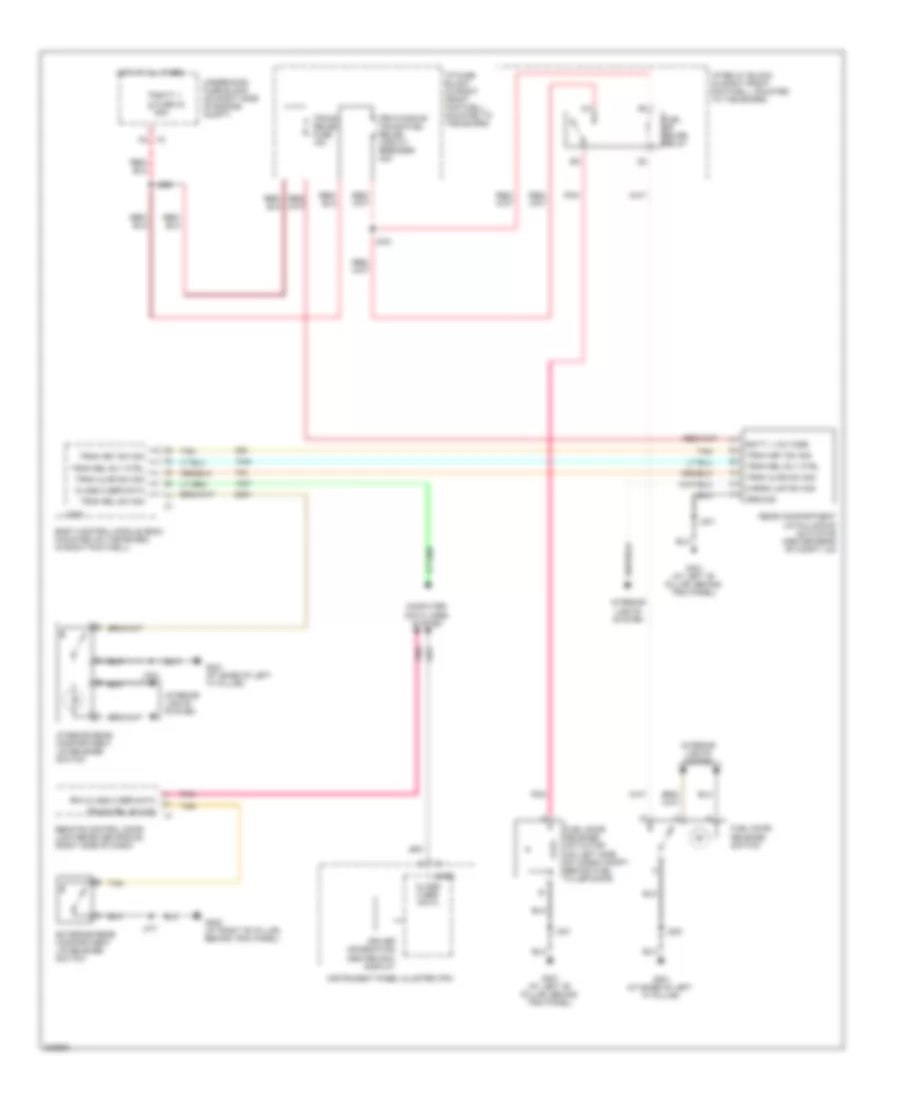
Defoggers Wiring Diagram for Chevrolet Corvette 2009
List of elements for Defoggers Wiring Diagram for Chevrolet Corvette 2009:
- A18
- A19
- Batt 2 fuse 29 30a
- C18
- C19
- Class 2 ser data
- Computer data lines system
- D10 x3
- Defog ctrl
- Defog ind
- Defog rly ctrl
- Defogger indicator
- Defogger switch
- Digital radio antenna
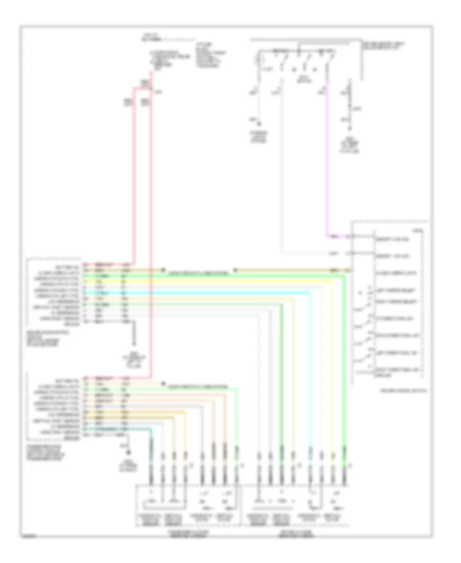
- Driver door control module (bottom center of driver door)
- Driver outside rearview mirror
- E10
- G201 (at base of left "a" pillar)
- G202 (at base of right "a" pillar)
- G301 (at left "b" pillar, behind trim panel)
- Hot at all times
- Htd mirror elmnt sply
- Hvac control module (center of dash, under radio)
- Ign
- J301
- J539
- J640
- Logic
- Nca
- Passenger door control module (bottom center of passenger door)
- Passenger outside rearview mirror
- Rear defog relay 40
- Rear window defogger grid
- Tan
- Under- hood fuse block (on right side of engine compt)
ELECTRONIC MUFFLER
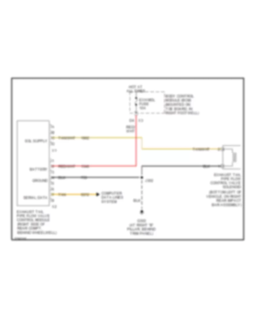
Electronic Muffler Wiring Diagram for Chevrolet Corvette 2009
List of elements for Electronic Muffler Wiring Diagram for Chevrolet Corvette 2009:
- (bottom left of vehicle, on right rear impact bar assembly)
- Battery
- Body control module (bcm) (mounted on toe board, in right footwell)
- Computer data lines system
- Exh mdl fuse 10a
- Exhaust tail pipe flow control valve solenoid
- Exhaust tail pipe flow valve control module (right side of rear compt, behind wheelwell)
- G302 (at right "b" pillar, behind trim panel)
- Ground
- Hot at all times
- J302
- Serial data
- Tan
- X3 d4
ELECTRONIC POWER STEERING
Electronic Power Steering Wiring Diagram for Chevrolet Corvette 2009
List of elements for Electronic Power Steering Wiring Diagram for Chevrolet Corvette 2009:
- (instrument panel body harness, near x231) j233
- (on left side of steering rack assembly) variable effort steering actuator
- Abs fuse 11 25a
- Abs fuse 27 40a
- Abs/mrrtd fuse 3 10a
- Battery positive voltage
- Can bus hi serial data
- Can bus high serial data
- Can bus lo serial data
- Can bus low serial data
- Computer data lines system
- D11
- E11
- E3 x2
- Electronic brake control module (ebcm) (at left front side of engine compt, on frame rail)
- G105 (on front left side of engine, above generator)
- G201 (at base of left "a" pillar)
- Gnd
- Ground
- Hi spd gmlan ser data +
- Hi spd gmlan ser data -
- Hot at all times
- Hot w/ run/crnk relay energized
- Ign 1 volt
- Ignition voltage
- J139
- J195
- J200
- J232 (instrument panel body harness, near x231)
- J275
- Pnk
- Red
- Sply volt
- Steering angle sensor (base of steering column, under dash)
- Tan
- Underhood fuse block (on right side of engine compt)
- Var efrt str sol ctrl
- X4 b1
- Yaw & lateral accelerometer sensor (under hvac control head)
ELECTRONIC SUSPENSION
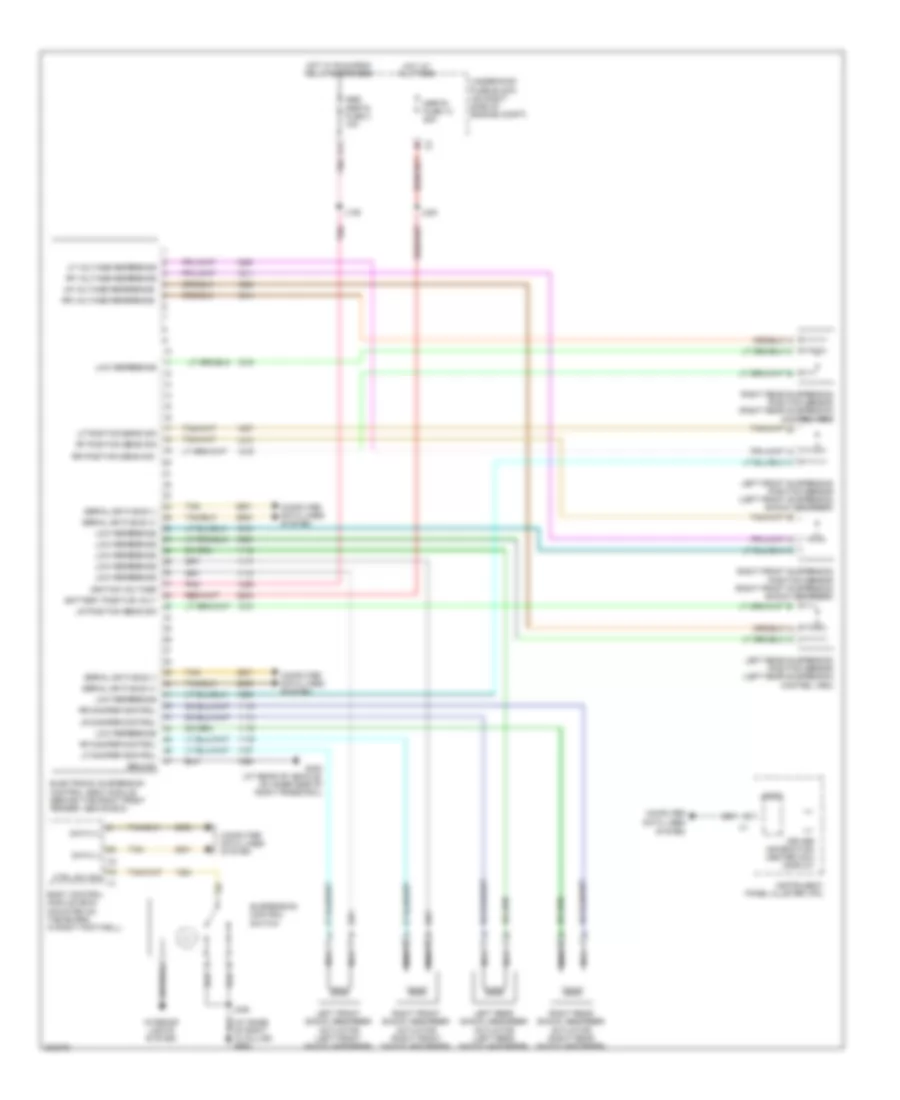
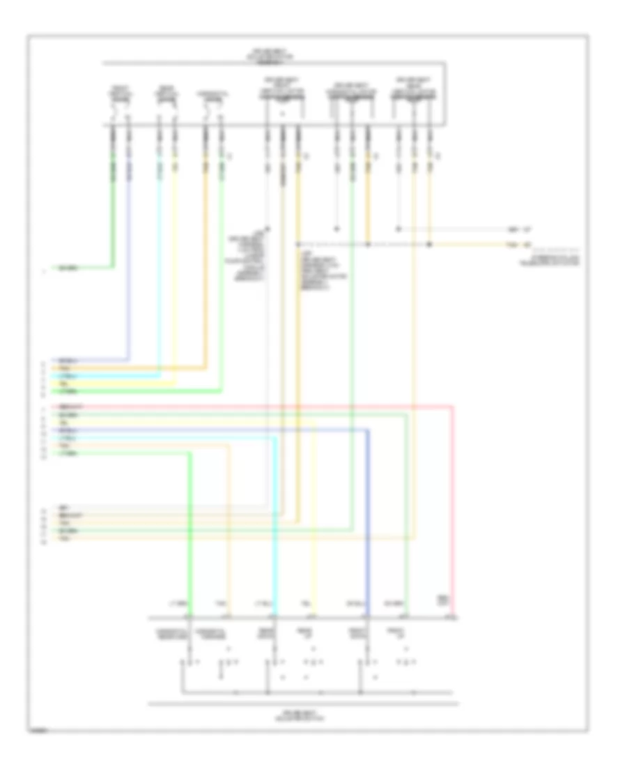
Electronic Suspension Wiring Diagram for Chevrolet Corvette 2009
List of elements for Electronic Suspension Wiring Diagram for Chevrolet Corvette 2009:
- Abs/ mrrtd fuse 3 10a
- Battery positive volt
- Body control module (bcm) (mounted on toe board, in right footwell)
- Computer
- Computer data lines system
- Ctrl sw sig
- Data (+)
- Data (-) x2
- Data lines system
- Driver information center (dic) display
- E11
- Electronic suspension control (esc) module (behind the right front fender, above ecm)
- G402 (at rear of vehicle, on inner side of right frame rail)
- Ground
- Hot at all times
- Hot w/ run/crnk relay energized
- Ignition voltage
- Instrument panel cluster (ipc)
- Interior lights system
- J139
- J246
- J420
- Left front shock absorber actuator (left front shock absorber)
- Left front suspension position sensor (left front suspension shock absorber)
- Left rear shock absorber actuator (left rear shock absorber)
- Left rear suspension position sensor (left rear suspension control arm)
- Lf damper control
- Lf position sens sig
- Lf voltage reference
- Logic
- Low reference
- Lr damper control
- Lr position sens sig
- Lr voltage reference
- Mrrtd fuse 13 25a
- Nca
- Pnk
- Rf damper control
- Rf position sens sig
- Rf voltage reference
- Right front shock absorber actuator (right front shock absorber)
- Right front suspension position sensor (right front suspension shock absorber)
- Right rear shock absorber actuator (right rear shock absorber)
- Right rear suspension position sensor (right rear suspension control arm)
- Rr damper control
- Rr position sens sig
- Rr voltage reference
- Serial data bus (+)
- Serial data bus (-)
- Suspension control switch
- Tan
- Underhood fuse block (on right side of engine compt)
ENGINE PERFORMANCE
6.2L VIN R
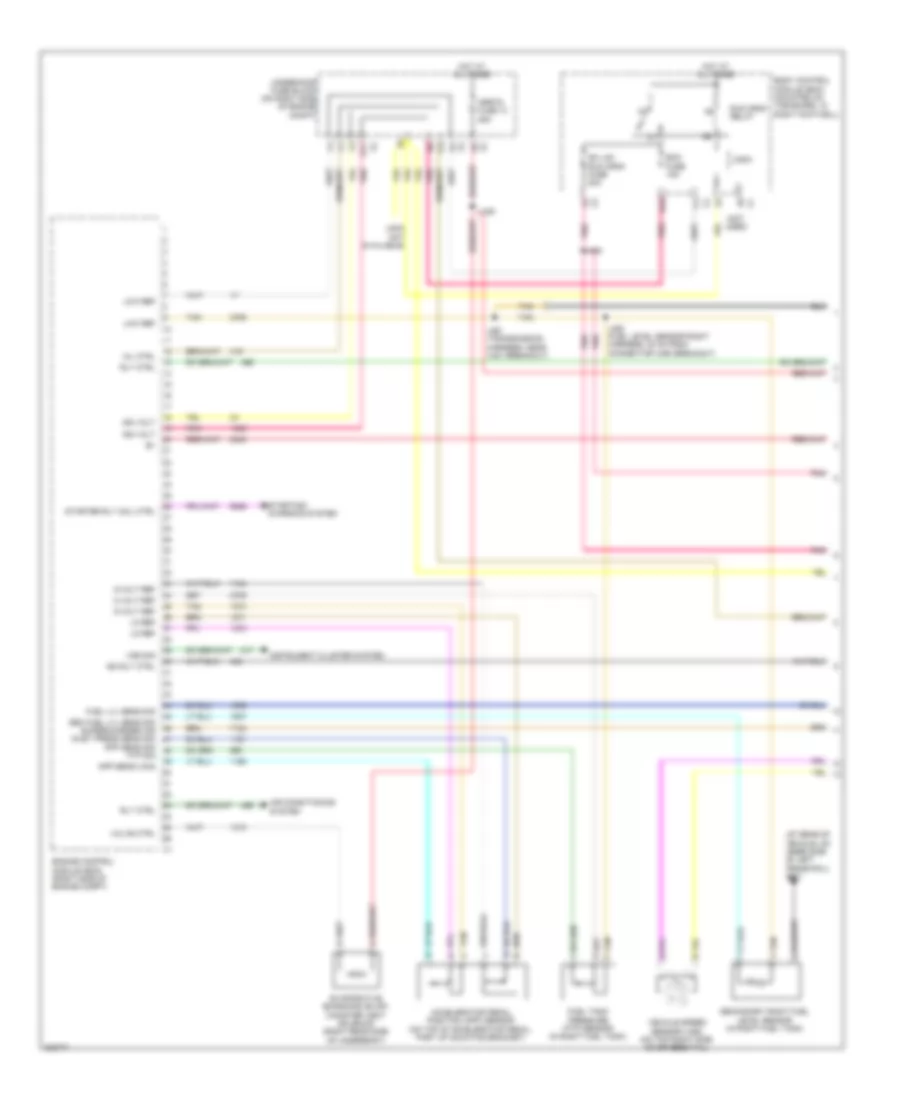
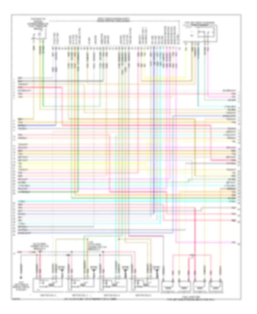
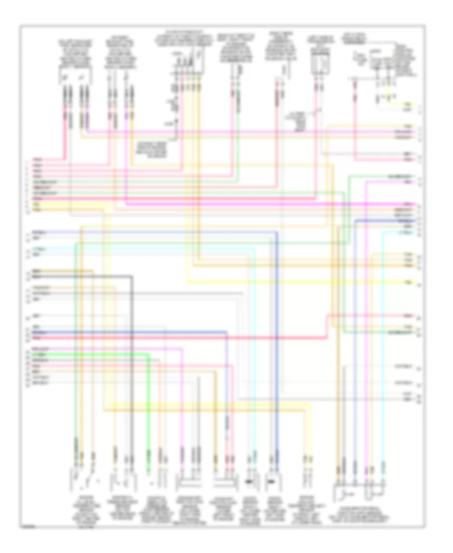
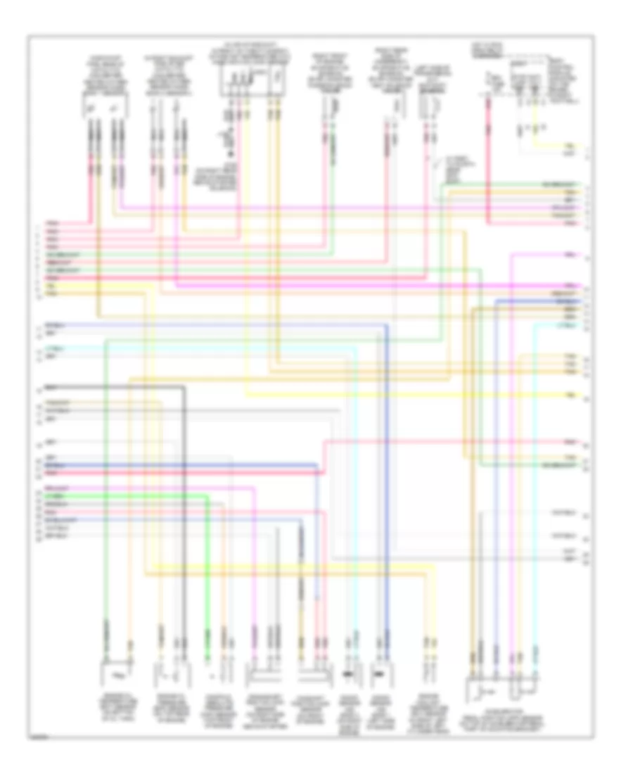
6.2L VIN R, Engine Performance Wiring Diagram (1 of 6) for Chevrolet Corvette 2009
List of elements for 6.2L VIN R, Engine Performance Wiring Diagram (1 of 6) for Chevrolet Corvette 2009:
- (at rear of vehicle, on inner side of left frame rail) g401
- (info not available)
- (not used)
- 5 volt ref
- 5-volt ref
- A11
- Accelerator pedal position (app) sensor (on top of accelerator pedal, part of mounting bracket)
- Air conditioning system
- App sens 2 sig
- App sens sig
- B10
- Body control module (bcm) (mounted on toe board, in right footwell)
- Ecm fuse 15a
- Engine control module (ecm) (right side of engine compt)
- Evaporative emissions (evap) canister vent solenoid (right rear side of underbody)
- Ftp sig
- Fuel lvl sens sig
- Fuel tank pressure (ftp) sensor (in right fuel tank)
- Gm lan run crnk fuse 20a
- Hot at all times
- Ign rly ctrl
- Ign volt
- Instrument cluster system
- J420
- J461 (transmission harness, near x421 breakout)
- J462 (fuel level sensor right harness, 20 cm from connector x460 breakout)
- J464
- Lo ref
- Logic
- Low ref
- Mil ctrl
- Mrrtd fuse 13 25a
- Pnk
- Rly ctrl
- Run crnk relay
- Sec fuel lvl sens sig supercharger air inlet press sens sig
- Secondary right fuel level sensor (in right fuel tank)
- Starter rly coil ctrl
- Starting/ charging system
- Tan
- Underhood fuse block (on right side of engine compt)
- Valve ctrl
- Vehicle speed sensor (vss) (on top right side of differential)
- Vss sig
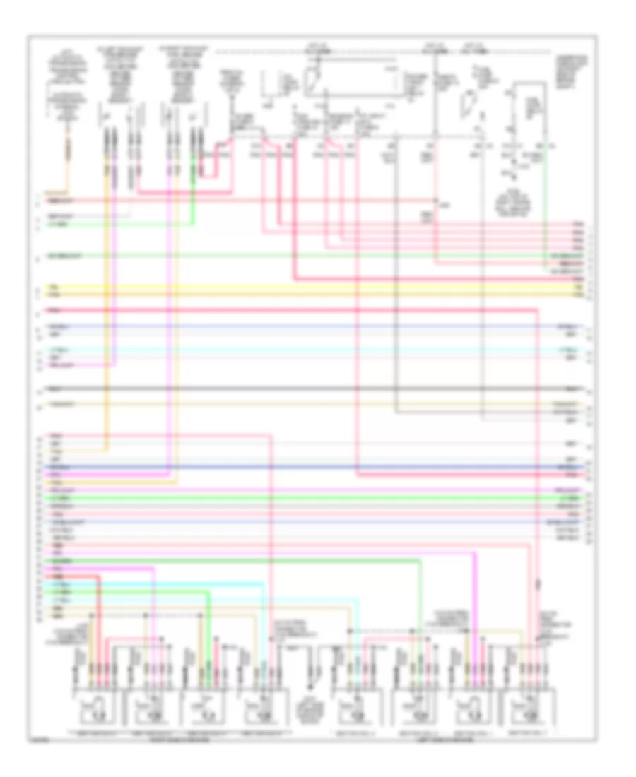
6.2L VIN R, Engine Performance Wiring Diagram (2 of 6) for Chevrolet Corvette 2009
List of elements for 6.2L VIN R, Engine Performance Wiring Diagram (2 of 6) for Chevrolet Corvette 2009:
- (in engine harness) j140
- (left side of transmission) skip shift solenoid
- A/c comp relay
- Clstr/ hud fuse 15a
- D10
- E10
- Ecm/tcm/ easy key fuse 56 15a
- Emission fuse 14 15a
- Evaporative emissions (evap) canister purge solenoid valve (top left front of engine)
- Even inj fuse 16 20a
- F13
- F14
- Fuel pump & sender assembly (in left fuel pump assembly)
- H13
- H14
- Heated oxygen sensor (ho2s) bank 1 sensor 1 (upstream of left catalytic converter)
- Heated oxygen sensor (ho2s) bank 1 sensor 2 (downstream of left catalytic converter)
- Heated oxygen sensor (ho2s) bank 2 sensor 1 (downstream of right catalytic converter)
- Heated oxygen sensor (ho2s) bank 2 sensor 2 (downstream of right catalytic converter)
- Hot at all times
- Man tran sol fuse 10 10a
- Nca
- O2 sen fuse 6 15a
- Odd inj fuse 12 20a
- Pnk
- Pnk a
- Power distribution system
- Powertrain ign 1 relay 44
- Pt input/ etc fuse 9 10a
- Red
- Supercharger bypass valve solenoid (top left front of engine)
- Tan
- Underhood fuse block (on right side of engine compt)
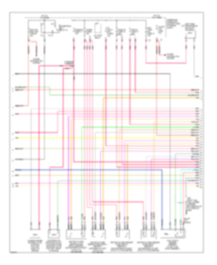
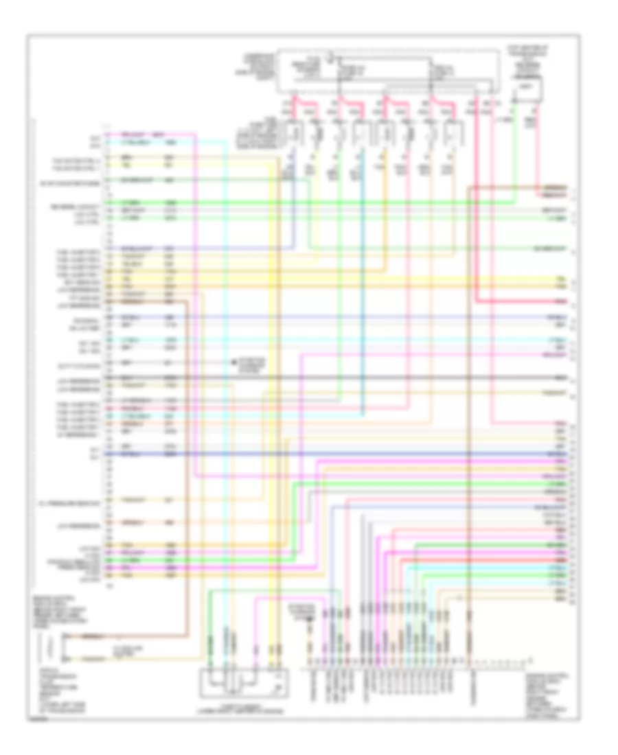
6.2L VIN R, Engine Performance Wiring Diagram (3 of 6) for Chevrolet Corvette 2009
List of elements for 6.2L VIN R, Engine Performance Wiring Diagram (3 of 6) for Chevrolet Corvette 2009:
- (right side of engine compt) engine control module (ecm)
- (top center of transmission) reverse lockout solenoid
- 5 volt ref
- 5-volt ref
- Baro sens sig
- Barometric pressure (baro) sensor (on right side of intake manifold)
- Boost sens sig
- Clutch pedal
- Clutch pedal position (cpp) sensor
- Computer data lines system
- Coolant pump ctrl
- Cooling fans system
- Ctrl
- Data bus+
- Data bus-
- Ect sens sig
- Engine control module (ecm) (right side of engine compt)
- Engine coolant temperature (ect) sensor (front of left cylinder head)
- Fan spd
- G106 (on right rear side of engine, above starter solenoid)
- Gen turn on sig
- Generator field duty cycle signal
- Gnd
- Ho2s hi sig b2s1
- Ho2s hi sig b2s2
- Ho2s htr ctrl b2s1
- Ho2s htr lo ctrl b2s2
- Ho2s lo sig b2s1
- Ho2s lo sig b2s2
- Intake air temperature (iat) sensor
- J106
- Low ref
- Manifold absolute pressure (map) sensor (top left side of engine)
- Mat sens sig
- Pnk
- Position sens sig
- Red
- Sens sig
- Skip shift sol
- Sol ctrl
- Starting/ charging system
- Tan
- Vss hi sig
- Vss low sig
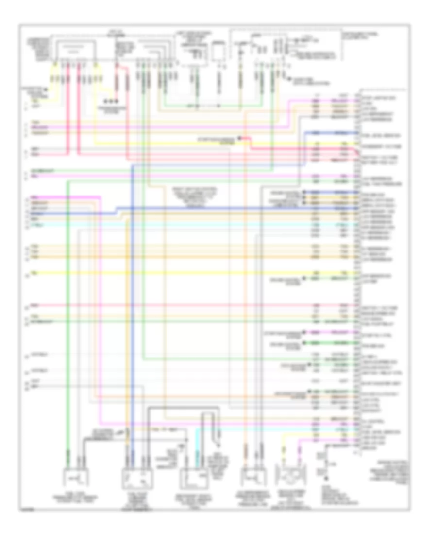
6.2L VIN R, Engine Performance Wiring Diagram (4 of 6) for Chevrolet Corvette 2009
List of elements for 6.2L VIN R, Engine Performance Wiring Diagram (4 of 6) for Chevrolet Corvette 2009:
- (lower left side of transmission) manual transmission fluid temperature sensor
- (on a/c high pressure line) a/c refrigerant pressure sensor
- (top center rear of engine) engine oil pressure (eop) sensor
- (top right of engine) g106
- Camshaft position (cmp) sensor (lower left front of engine)
- Computer data lines system
- Crankshaft position (ckp) sensor (lower right rear of engine)
- Driver information center (dic) display
- Fuel injectors (top right side of engine, below fuel rail)
- G201 (at base of left "a" pillar)
- Gnd
- Ign
- Instrument panel cluster (ipc)
- J106
- J149
- Knock sensor (ks) 1
- Knock sensor (ks) 2
- Logic
- Low speed
- Malfunction indicator lamp
- Mass air flow (maf)/ intake air temperature (iat) sensor (in air intake duct, in front of throttle body)
- Pnk
- Red
- Tan
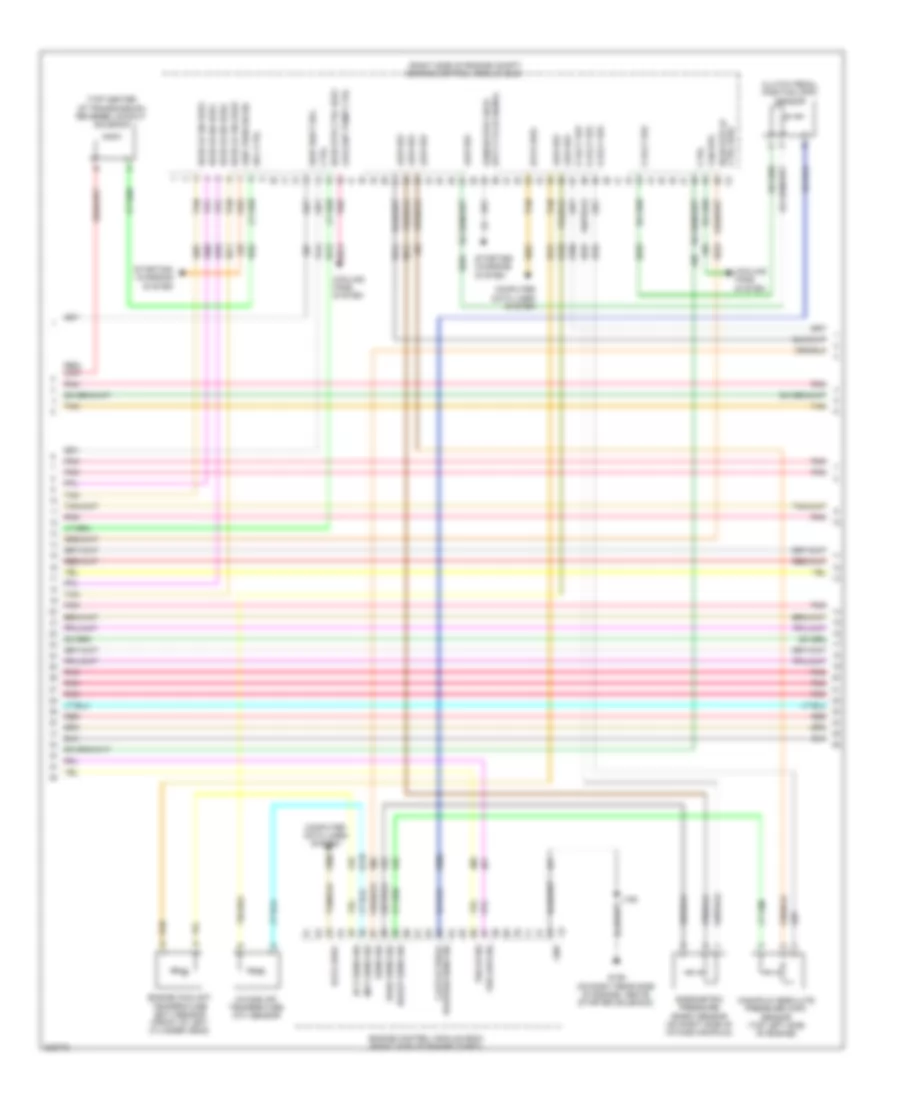
6.2L VIN R, Engine Performance Wiring Diagram (5 of 6) for Chevrolet Corvette 2009
List of elements for 6.2L VIN R, Engine Performance Wiring Diagram (5 of 6) for Chevrolet Corvette 2009:
- (6.0 cm from connector x140 breakout) j131
- (on valve cover, top of respective cylinder)
- (right side of engine compt) engine control module (ecm)
- (top left front of engine) throttle body
- (top right of engine) supercharger air inlet pressure sensor
- 5 volt ref
- Fuel inj 2 ctrl
- Fuel inj 3 ctrl
- Fuel injectors (top left side of engine, below fuel rail)
- G107 (left side of engine, middle of block)
- Ho2s hi sig b1s1
- Ho2s hi sig b1s2
- Ho2s lo sig b1s1
- Ho2s lo sig b1s2
- Ic 1 ctrl
- Ic 4 ctrl
- Ic 5 ctrl
- Ic 7 ctrl
- Ic 8 ctrl
- Ign volt
- Ignition coil 2
- Ignition coil 4
- Ignition coil 6
- Ignition coil 8
- J133
- J135 (2.5 cm from connector x140 breakout)
- J150
- Ks 1 sig
- Ks 2 sig
- Lo ref
- Low ref
- Nca
- Pnk
- Red
- Sens rtn
- Spark plug
- Tac mtr ctrl 1
- Tac mtr ctrl 2
- Tan
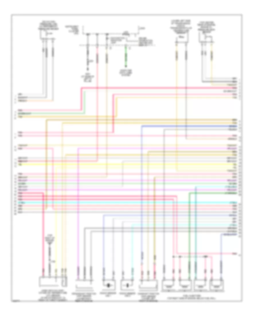
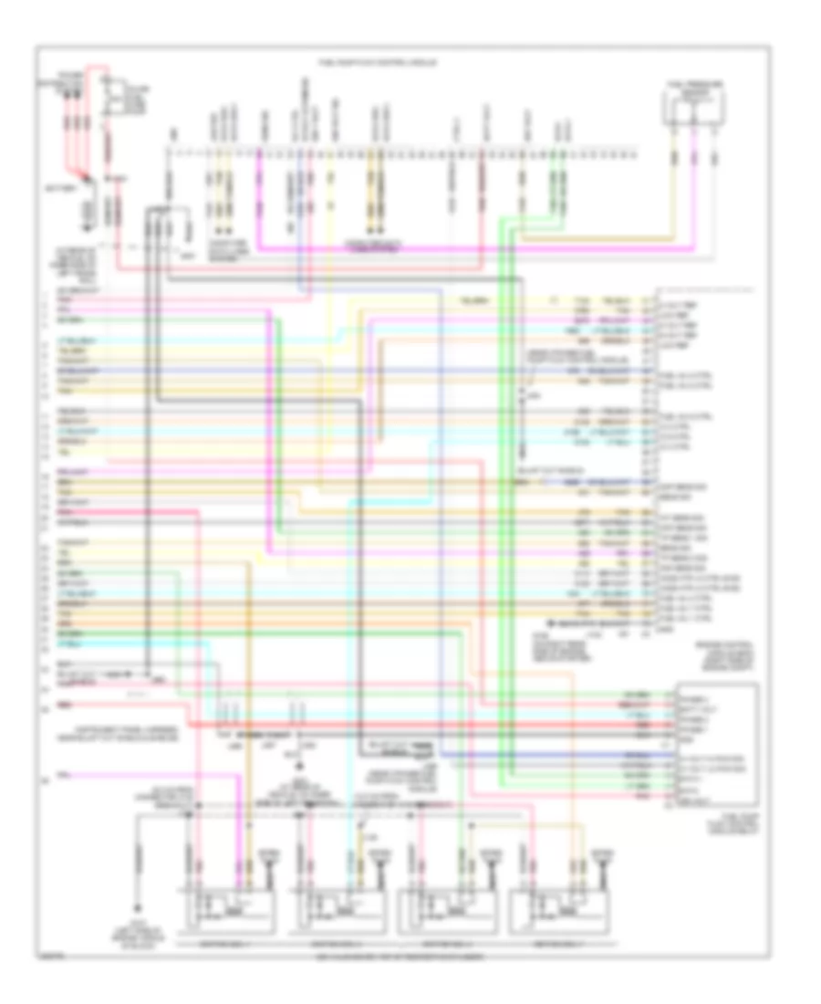
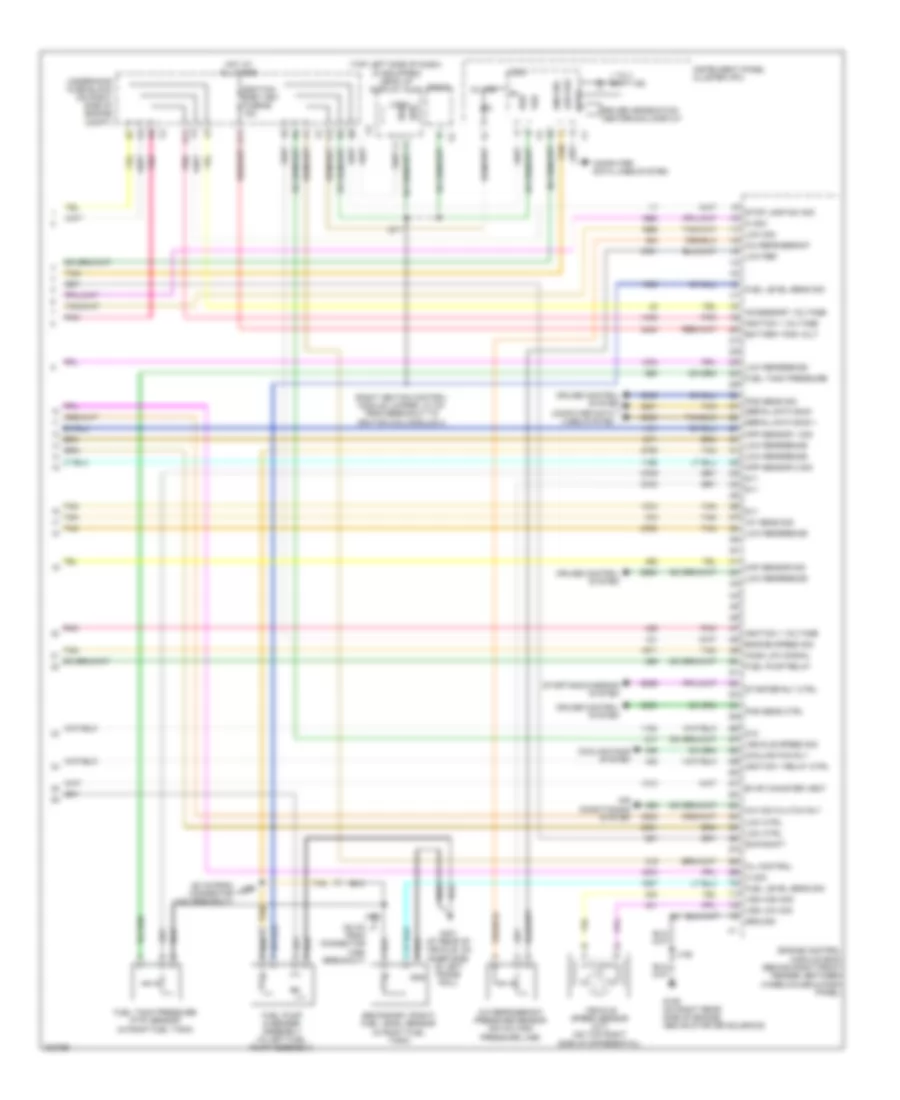
6.2L VIN R, Engine Performance Wiring Diagram (6 of 6) for Chevrolet Corvette 2009
List of elements for 6.2L VIN R, Engine Performance Wiring Diagram (6 of 6) for Chevrolet Corvette 2009:
- (12.0 cm from connector x140 breakout)
- (6.0 cm from connector x140 breakout) j142
- (at rear of vehicle, on inner side of left frame rail)
- (near 3-phase fuel pump flow control module)
- (on valve cover, top of respective cylinder)
- 30a
- 5 volt ref
- 5-volt ref
- Batt volt
- Battery
- Ckp sens sig
- Cmp sens sig
- Computer data lines system
- Ctrl 2
- Data +
- Data -
- Data bus +
- Data bus -
- Data-
- Engine control module (ecm) (right side of engine compt)
- Fuel inj 1 ctrl
- Fuel inj 4 ctrl
- Fuel inj 5 ctrl
- Fuel inj 6 ctrl
- Fuel inj 7 ctrl
- Fuel inj 8 ctrl
- Fuel pressure sensor
- Fuel pump flow control module
- Fuel pump flow control module relay
- G106 (on right rear side of engine, above starter)
- G107 (left side of engine, middle of block)
- G401
- G401 (at rear of vehicle, on inner side of left frame rail)
- Gnd
- Hi volt hi pwm sig
- Hi volt lo pwm sig
- Ho2s htr lo ctrl b1s2
- Iat sens sig
- Ic 2 ctrl
- Ic 3 ctrl
- Ic 6 ctrl
- Ign 1 volt
- Ign volt
- Ign volt sig
- Ignition coil 1
- Ignition coil 3
- Ignition coil 5
- Ignition coil 7
- Inline fuel fuse pump
- J106
- J144
- J146
- J444
- J452
- J453
- J454
- J456 (near 3-phase fuel pump flow control module)
- J463
- J466
- J467
- Low ref
- Maf sens sig
- Nca
- Phase 1
- Phase 2
- Phase 3
- Pnk
- Power distribution system
- Red
- Ref volt
- Rly ctrl
- Sens sig
- Spark plug
- Tan
- Tp sens 1 sig
- Tp sens 2 sig
6.2L VIN W
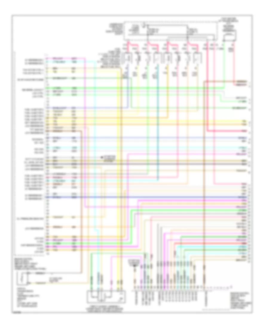
6.2L VIN W, Engine Performance Wiring Diagram (1 of 4) for Chevrolet Corvette 2009
List of elements for 6.2L VIN W, Engine Performance Wiring Diagram (1 of 4) for Chevrolet Corvette 2009:
- (top center of transmission) (m/t) reverse lockout solenoid
- 5v reference 1
- 5v reference 2
- B9 x2
- C10
- Ckp sensor
- Cmp sensor
- Duty cycle sig
- Ect sensor sig
- Engine control module (ecm) (behind right front fender, between wheelhouse & dash panel)
- Evap canister purge
- Even inj fuse 16 20a
- Fuel injector 1
- Fuel injector 2
- Fuel injector 3
- Fuel injector 4
- Fuel injector 5
- Fuel injector 6
- Fuel injector 7
- Fuel injector 8
- Fuel injectors (1, 3, 5 & 7: top left side of engine, below fuel rail) (2, 4, 6 & 8: top right side of engine, below fuel rail)
- Hi sig
- Ic 1 ctrl
- Ic 2 ctrl
- Ic 3 ctrl
- Ic 4 ctrl
- Ic 5 ctrl
- Ic 6 ctrl
- Ic 7 ctrl
- Ic 8 ctrl
- Ks 1 sig
- Ks 2 sig
- Ks signal
- Low ctrl
- Low ref
- Low reference
- Low sig
- Manual transmission fluid temperature (tft) sensor (m/t) (lower left side of transmission)
- Map sensor signal
- Odd inj fuse 12 20a
- Oil level sw sig
- Oil pressure sens sig
- Park/neu sig
- Pnk
- Red
- Reverse lockout
- Starting/ charging system
- Tac motor ctrl 1
- Tac motor ctrl 2
- Tan
- Tft sns sig
- Throttle body assembly (upper front center of engine, forward of intake manifold)
- To inj fuses (diagram 2 of 4)
- Tp sns 1 sig
- Tp sns 2 sig
- Turn on sig
- Underhood fuse block (on right side of engine compt)
- W/ cooling system
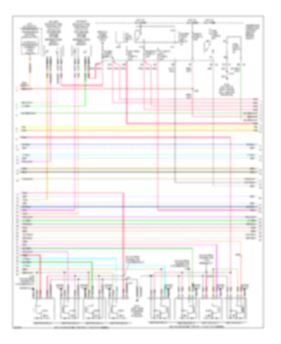
6.2L VIN W, Engine Performance Wiring Diagram (2 of 4) for Chevrolet Corvette 2009
List of elements for 6.2L VIN W, Engine Performance Wiring Diagram (2 of 4) for Chevrolet Corvette 2009:
- (12.5 cm from connector x140 breakout) j146
- (6.0 cm from connector x140 breakout)
- (a/t) automatic transmission
- (on left exhaust pipe, forward of catalytic converter) heated oxygen sensor (ho2s) bank 1 sensor 1
- (on right exhaust pipe, forward of catalytic converter) heated oxygen sensor (ho2s) bank 2 sensor 1
- (on valve cover, top of 1, 3, 5 & 7 cylinders)
- (on valve cover, top of 2, 4, 6 & 8 cylinders)
- A/c comp relay
- Automatic transmission internal
- C10 x1
- D10
- E10
- Emission fuse 14 15a
- F13
- F14
- From inj fuses (diagram 1 of 4)
- Fuel pump fuse 20 20a
- Fuel pump relay
- G102 (on top of right frame rail, ground for sp102)
- G107 (left side of engine, middle of block)
- H13
- H14
- Hot at all times
- Ignition coil 1
- Ignition coil 2
- Ignition coil 3
- Ignition coil 4
- Ignition coil 5
- Ignition coil 6
- Ignition coil 7
- Ignition coil 8
- J102
- J131
- J133
- J135 (12.5 cm from connector x140 breakout)
- J142
- J144
- J420
- Man tran sol fuse 10 10a
- Mode
- Mrrtd fuse 13 25a
- Nca
- O2 sen fuse 6 15a
- Pnk
- Pnk d
- Power- train ign 1 relay
- Pt input/ etc fuse 9 10a
- Red
- Red c
- Spark plug
- Switch
- Tan
- Transmission control module (tcm)
- Underhood fuse block (on right side of engine compt)
- X2 a6
- X2 b6
6.2L VIN W, Engine Performance Wiring Diagram (3 of 4) for Chevrolet Corvette 2009
List of elements for 6.2L VIN W, Engine Performance Wiring Diagram (3 of 4) for Chevrolet Corvette 2009:
- (back of throttle body, right front of engine) evaporative emission (evap) canister purge solenoid valve
- (in air intake duct, in front of throttle body) intake air temperature (iat)/ mass air flow (maf) sensor
- (left side of transmission) (m/t) skip shift solenoid
- (on left exhaust pipe, rearward of catalytic converter) heated oxygen sensor (ho2s) bank 1 sensor 2
- (on right exhaust pipe, rearward of catalytic converter)
- (on right rear side of engine, above starter solenoid)
- (right rear side of underbody) evaporative emission (evap) canister vent solenoid valve
- Accelerator pedal position (app) sensor (on top of accelerator pedal, part of mounting bracket)
- Accy volt sig
- B10
- Body control module (mounted on toe board, in right footwell)
- Camshaft position (cmp) sensor (lower left front of engine)
- Crankshaft position (ckp) sensor (on lower right side of engine, behind starter)
- Ecm fuse 15a
- Engine coolant temperature (ect) sensor (in front left side of left cylinder head)
- Engine oil level/ temperature sensor (on bottom right center of engine oil pan)
- Engine oil pressure (eop) sensor (on top center rear of engine)
- G106
- Gnd
- Heated oxygen sensor (ho2s) bank 2 sensor 2
- Hot w/ run crank relay energized
- Ign 1
- Knock sensor bank 1 (on center left side of engine)
- Knock sensor bank 2 (on lower center right side of engine)
- Logic
- Maf
- Manifold absolute pressure (map) sensor (front center of engine, behind throttle body)
- Nca
- Pnk
- Red
- Stop lamp sig
- Tan
- W/ first to fourth gear skip shift
6.2L VIN W, Engine Performance Wiring Diagram (4 of 4) for Chevrolet Corvette 2009
List of elements for 6.2L VIN W, Engine Performance Wiring Diagram (4 of 4) for Chevrolet Corvette 2009:
- (20 cm from connector x420 breakout)
- (20 cm from connector x460 breakout)
- (left side of dash) (if equipped) head up display (hud)
- (right ignition control module jumper, 4.0 cm from breakout to ignition coil/ module 4)
- 1 to 4 shift ind
- 5v ref 2
- 5v reference 1
- A/c com clutch rly
- A/c refrigerant
- A/c refrigerant pressure sensor (on a/c high pressure line)
- A11
- Accessory voltage
- Air conditioning system
- App sensor 1 sig
- App sensor 2 sig
- Battery pos volt
- Computer data lines system
- Cooling fan rly
- Cooling fans system
- Cruise control system
- Data
- Driver information center (dic) display
- Ecm/tcm/ easy key fuse 56 15a
- Engine control module (ecm) (behind right front fender, between wheelhouse & dash panel)
- Engine speed sig
- Ess
- Evap canister vent
- Fuel level sens sig
- Fuel pump & sender assembly (in left fuel pump assembly)
- Fuel pump relay
- Fuel tank pressure
- Fuel tank pressure (ftp) sensor (in right fuel tank)
- G106 (on right rear side of engine, above starter solenoid)
- G401 (at rear of vehicle, on inner side of left frame rail)
- Gnd
- Ground
- Hi sig
- Hot at all times
- Iat sens sig
- Ignition 1 relay ctrl
- Ignition 1 voltage
- Instrument panel cluster (ipc)
- J106
- J211
- J460
- J462
- Logic
- Low ctrl
- Low ref
- Low reference
- Low sig
- Low signal
- Maf sensor sig
- Mil control
- Mil ind
- Navigation & sound
- Pnk
- Pos sen sig
- Radio
- Secondary (right) fuel level sensor (in right fuel tank)
- Serial data bus +
- Serial data bus -
- Skip/shift
- Sns sig
- Start rly ctrl
- Starting/charging system
- Stop lamp sw sig
- Systems
- Tan
- Transmissions system
- Underhood fuse block (on right side of engine compt)
- Vehicle speed sensor (vss) (m/t) (on top right side of differential)
- Vehicle speed sig
- Vss
- Vss high sig
- Vss low sig
7.0L VIN E
7.0L VIN E, Engine Performance Wiring Diagram (1 of 4) for Chevrolet Corvette 2009
List of elements for 7.0L VIN E, Engine Performance Wiring Diagram (1 of 4) for Chevrolet Corvette 2009:
- (top center of transmission) (m/t) reverse lockout solenoid
- 5v reference 1
- 5v1
- 5v2
- B9 x2
- C10
- Ckp sensor
- Cmp sensor
- Duty cycle sig
- Ect sens sig
- Engine control module (ecm) (behind right front fender, between wheelhouse & dash panel)
- Evap canister purge
- Even inj fuse 16 20a
- Fuel injector 1
- Fuel injector 2
- Fuel injector 3
- Fuel injector 4
- Fuel injector 5
- Fuel injector 6
- Fuel injector 7
- Fuel injector 8
- Fuel injectors (1, 3, 5 & 7: left side of engine) (2, 4, 6 & 8: right side of engine)
- Hi sig manifold absolute press sens sig hi sig
- Ic 1 ctrl
- Ic 2 ctrl
- Ic 3 ctrl
- Ic 4 ctrl
- Ic 5 ctrl
- Ic 6 ctrl
- Ic 7 ctrl
- Ic 8 ctrl
- Ks 1 sig
- Ks low ref
- Ks signal
- Low ctrl
- Low ref
- Low reference
- Low sig
- Manual transmission fluid temperature sensor (m/t) (lower left side of transmission)
- Odd inj fuse 12 20a
- Oil pressure sens sig
- Park/neu sig
- Pnk
- Red
- Reverse lockout
- Starting/ charging system
- Tac motor ctrl 1
- Tac motor ctrl 2
- Tan
- Tft sns sig
- Throttle body (upper front center of engine)
- To 02 sens fuse (diagram 2 of 4)
- Tp sns 1 sig
- Tp sns 2 sig
- Turn on sig
- Underhood fuse block (on right side of engine compt)
- W/ cooling system
7.0L VIN E, Engine Performance Wiring Diagram (2 of 4) for Chevrolet Corvette 2009
List of elements for 7.0L VIN E, Engine Performance Wiring Diagram (2 of 4) for Chevrolet Corvette 2009:
- (12.5 cm from connector x140 breakout) j146
- (6.0 cm from connector x140 breakout)
- (6.0 cm from connector x140 breakout) j131
- (a/t) automatic transmission
- (in left exhaust pipe before catalytic converter)
- (in right exhaust pipe, before
- (left side of engine)
- (right side of engine)
- A/c comp relay
- A6 x2
- Automatic transmission internal lock switch
- C10 x1
- Catalytic converter)
- D10
- E10
- Emission fuse 14 15a
- F13
- F14
- From inj fuses (diagram 1 of 4)
- Fuel pump fuse 20 20a
- Fuel pump relay
- G102 (on top of right frame rail, ground for sp102)
- G107 (left side of engine, middle of block)
- H13
- H14
- Heated oxygen sensor (ho2s) bank 1 sensor 1
- Heated oxygen sensor (ho2s) bank 2 sensor 1
- Hot at all times
- Ignition coil 1
- Ignition coil 2
- Ignition coil 3
- Ignition coil 4
- Ignition coil 5
- Ignition coil 6
- Ignition coil 7
- Ignition coil 8
- J102
- J133
- J135 (12.5 cm from connector x140 breakout)
- J142
- J144
- J420
- Man tran sol fuse 10 10a
- Mrrtd fuse 13 25a
- Nca
- O2 sen fuse 6 15a
- Plug spark
- Pnk
- Power- train ign 1 relay
- Pt input/ etc fuse 9 10a
- Red
- Spark plug
- Tan
- Transmission control module (tcm)
- Underhood fuse block (on right side of engine compt)
- X2 b6
7.0L VIN E, Engine Performance Wiring Diagram (3 of 4) for Chevrolet Corvette 2009
List of elements for 7.0L VIN E, Engine Performance Wiring Diagram (3 of 4) for Chevrolet Corvette 2009:
- (in air intake duct, in front of throttle body) intake air temperature (iat)/ mass air flow (maf) sensor
- (in exhaust pipe, rear of catalytic converter) heated oxygen sensor (ho2s) bank 1 sensor 2
- (in right exhaust pipe after catalytic converter) heated oxygen sensor (ho2s) bank 2 sensor 2
- (left side of transmission) (m/t) skip shift solenoid
- (right front of engine) evaporative emission (evap) canister
- (right rear side of underbody) evaporative emission (evap) canister
- Accelerator pedal position (app) sensor (on top of accelerator pedal, part of mounting bracket)
- Accy volt sig
- B10
- Body control module (mounted on toe board, in right footwell)
- Camshaft position (cmp) sensor (on front of engine)
- Crankshaft position (ckp) sensor (on right side of engine above starter)
- Ecm fuse 15a
- Engine coolant temperature (ect) sensor (in front left side of left cylinder head)
- Engine oil pressure (eop) sensor (on top rear of engine)
- Engine oil temperature (eot) sensor (on bottom of oil tank)
- G106 (on right rear side of engine, above starter solenoid)
- Gnd
- Hot w/ run crnk relay energized
- Ign 1
- Knock sensor (ks) bank 1 (left side of engine)
- Knock sensor (ks) bank 2 (on right side of engine)
- Logic
- Maf
- Manifold absolute pressure (map) sensor (top front of engine)
- Nca
- Pnk
- Purge solenoid valve
- Red
- Stop lamp sig
- Tan
- Vent solenoid valve
- W/ first to fourth gear skip shift
7.0L VIN E, Engine Performance Wiring Diagram (4 of 4) for Chevrolet Corvette 2009
List of elements for 7.0L VIN E, Engine Performance Wiring Diagram (4 of 4) for Chevrolet Corvette 2009:
- (20 cm from connector x420 breakout)
- (20 cm from connector x460 breakout)
- (right ignition control module jumper, 4.0 cm from breakout to ignition coil/module 4)
- (top left side of dash) (if equipped) head up display (hud)
- 1 to 4 shift ind
- 5v1
- 5v2
- A/c com clutch rly
- A/c refrigerant
- A/c refrigerant pressure sensor (on a/c high pressure line)
- Accessory voltage
- Air conditioning system
- App sensor 1 sig
- App sensor 2 sig
- Battery pos volt
- Computer data lines system
- Cooling fan rly
- Cooling fans system
- Cruise control system
- D11
- Data
- Driver information center (dic) display
- Ecm/tcm/ easy key fuse 56 15a
- Engine control module (ecm) (behind right front fender, between wheelhouse & dash panel)
- Engine speed sig
- Ess
- Evap canister vent
- F4 a11
- Fuel level sens sig
- Fuel pump & sender assembly (in left fuel pump assembly)
- Fuel pump relay
- Fuel tank pressure
- Fuel tank pressure (ftp) sensor (in right fuel tank)
- G106 (on right rear side of engine, above starter solenoid)
- G401 (at rear of vehicle, on inner side of left frame rail)
- Gnd
- Ground
- Hi sig
- Ho2s low signal
- Hot at all times
- Iat sens sig
- Ignition 1 relay ctrl
- Ignition 1 voltage
- Instrument panel cluster (ipc)
- J106
- J211
- J460
- J462
- Logic
- Low ctrl
- Low ref
- Low reference
- Low sig
- Maf sensor sig
- Mil control
- Mil ind
- Pnk
- Pos sens ctrl
- Pos sens sig
- Radio
- Secondary (right) fuel level sensor (in right fuel tank)
- Serial data bus +
- Serial data bus -
- Skip/shift
- Sns sig
- Starter rly ctrl
- Starting/charging system
- Stop lamp sw sig
- Tan
- Underhood fuse block (on right side of engine compt)
- Vehicle speed sensor (m/t) (on top right side of differential)
- Vehicle speed sig
- Vss
- Vss high sig
- Vss low sig
EXTERIOR LIGHTS
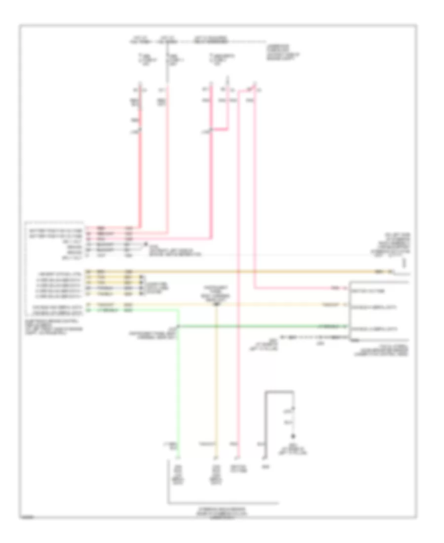
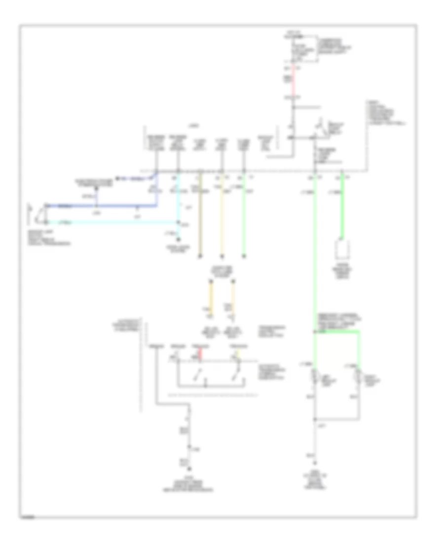
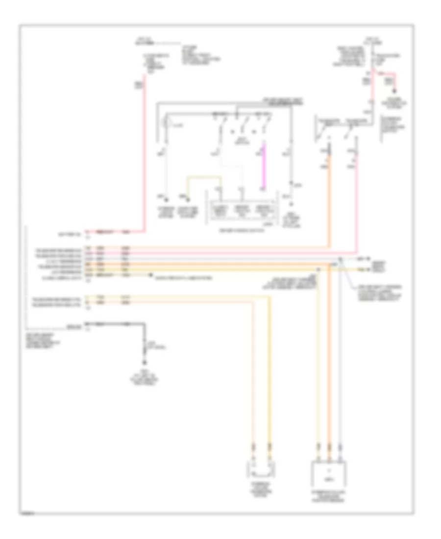
Backup Lamps Wiring Diagram for Chevrolet Corvette 2009
List of elements for Backup Lamps Wiring Diagram for Chevrolet Corvette 2009:
- (rear body harness, approximately 17.5 cm from right license lamp breakout) j470
- Automatic transmission (if equipped)
- Automatic transmission internal mode switch
- B11
- Backup lamp rly ctrl
- Backup lamp switch (right side of manual transmission)
- Bck/up lamp relay
- Body control module (bcm) (mounted on toe board, in right footwell)
- Class 2 ser data
- Computer data lines system
- D10
- Door locks system
- Electronic power steering system
- G106 (on right rear side of engine, above starter solenoid)
- G302 (at right "b" pillar, behind trim panel)
- Gm lan ser data bus +
- Gm lan ser data bus -
- Ground
- Hi spd ser data +
- Hi spd ser data -
- Hot at all times
- Inside rearview mirror (isrvm)
- J100
- J106
- J218
- J471
- Left backup lamp
- Logic
- M/t
- Red
- Reverse lamp relay control
- Reverse lamps fuse 10a
- Right backup lamp
- Stop/ b/u/lamps fuse 5 15a
- Tan
- Transmission control module (tcm)
- Trs a sig
- Trs b sig
- Underhood fuse block (on right side of engine compt)
Exterior Lamps Wiring Diagram (1 of 2) for Chevrolet Corvette 2009
List of elements for Exterior Lamps Wiring Diagram (1 of 2) for Chevrolet Corvette 2009:
- (6.2l supercharged: right side of engine compt) (except 6.2l supercharged: behind right front fender, between wheelhouse & dash panel) engine control module (ecm)
- (6.2l vin w) automatic transmission
- (in forward lamp harness, 26 cm from horn assembly breakout) j105
- A12
- Auto
- B11
- Body control module (bcm) (mounted on toe board, in right footwell)
- Brake pedal position (bpp) sensor (mounted on brake pedal bracket)
- Brk pos sens sig
- C11
- C12
- Center high mounted stop lamp (chmsl)
- Class 2 ser data
- Computer data lines system
- Control solenoid valve assembly
- F10
- F11
- G101 (on left frame rail)
- G102 (on top of right frame rail, ground for sp102)
- G201 (at base of left "a" pillar)
- G302 (at right "b" pillar, behind trim panel)
- Hazard sw sig
- Head
- Hot at all times
- Instrument cluster system
- J101
- J102
- J119
- J120
- J275
- J471
- Left front side marker lamp
- Left park/ turn signal lamp
- Lf trn sig vlt
- Logic
- Low ref
- Lt trn sig sw
- Off
- Park
- Park lamp relay 37
- Pk lamps fuse 8 10a
- Prk lmp rly cntl
- Prk lmp sw on sig
- Rf trn sig vlt
- Right front side marker lamp
- Right park/ turn signal lamp
- Rt trn sig sw
- Stop/ b/u/ lamps fuse 5 15a
- Stp lmp sw sig
- Tan
- Turn
- Turn signal/ multi-function switch
- Under- hood fuse block (on right side of engine compt)
- Underhood fuse block (on right side of engine compt)
- Underhood fuse block (on right side of engine compt) x3
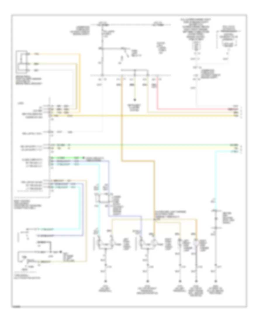
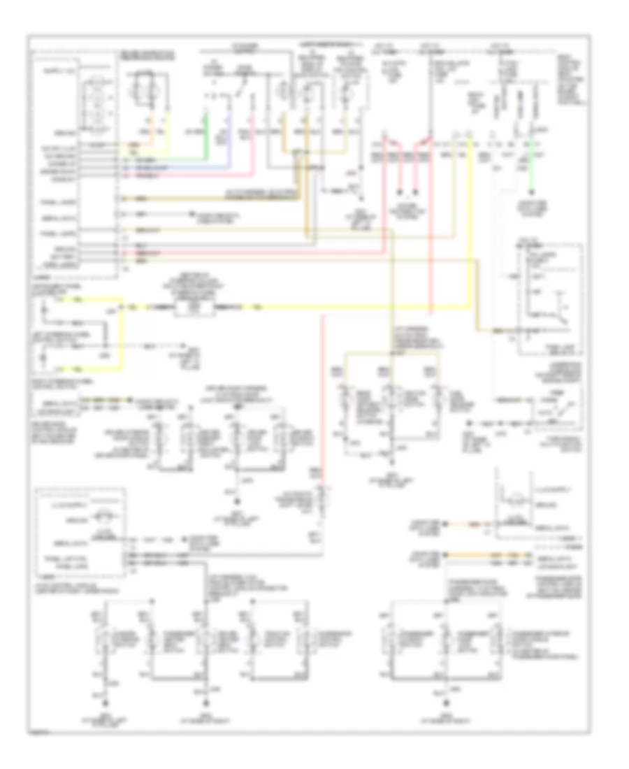
Exterior Lamps Wiring Diagram (2 of 2) for Chevrolet Corvette 2009
List of elements for Exterior Lamps Wiring Diagram (2 of 2) for Chevrolet Corvette 2009:
- (rear body harness, 11 cm from connector x455 breakout) j459
- (rear body harness, 6.5 cm from connector x455 breakout) j455
- (w/ rear fog lamp)
- Body control module (bcm) (mounted on toe board, in right footwell)
- Cluster/ hud fuse 15a
- Computer data lines system
- D10
- G201 (at base of left "a" pillar)
- G302 (at right "b" pillar, behind trim panel)
- Hazard switch
- Hot at all times
- Hzrd flash sig
- Instrument panel cluster
- Interior lights system
- Ipc
- Ipc class 2 data
- J200
- J457 (rear body harn, 15 cm from connector x455 breakout)
- J471
- Left inner tail/ stop & turn signal lamp (w/o rear fog lamp)
- Left license lamp
- Left outer tail/ stop & turn signal lamp (w/o rear fog lamp)
- Left rear side marker lamp
- Left rear turn signal lamp
- Left tail/ stop lamp
- Left turn sig ind
- Logic
- Off
- Power distribution system
- Right inner tail/ stop & turn signal lamp (w/o rear fog lamp)
- Right license lamp
- Right outer tail/ stop & turn signal lamp (w/o rear fog lamp)
- Right rear side marker lamp
- Right rear turn signal lamp (w/ rear fog lamp)
- Right tail/ stop lamp (w/ rear fog lamp)
- Right turn sig ind
- Stop lamp relay
- Stp lmp rly ctrl
- Stp lmp sw sig
- Tan
- W/ rear fog lamp
- W/o rear fog lamp
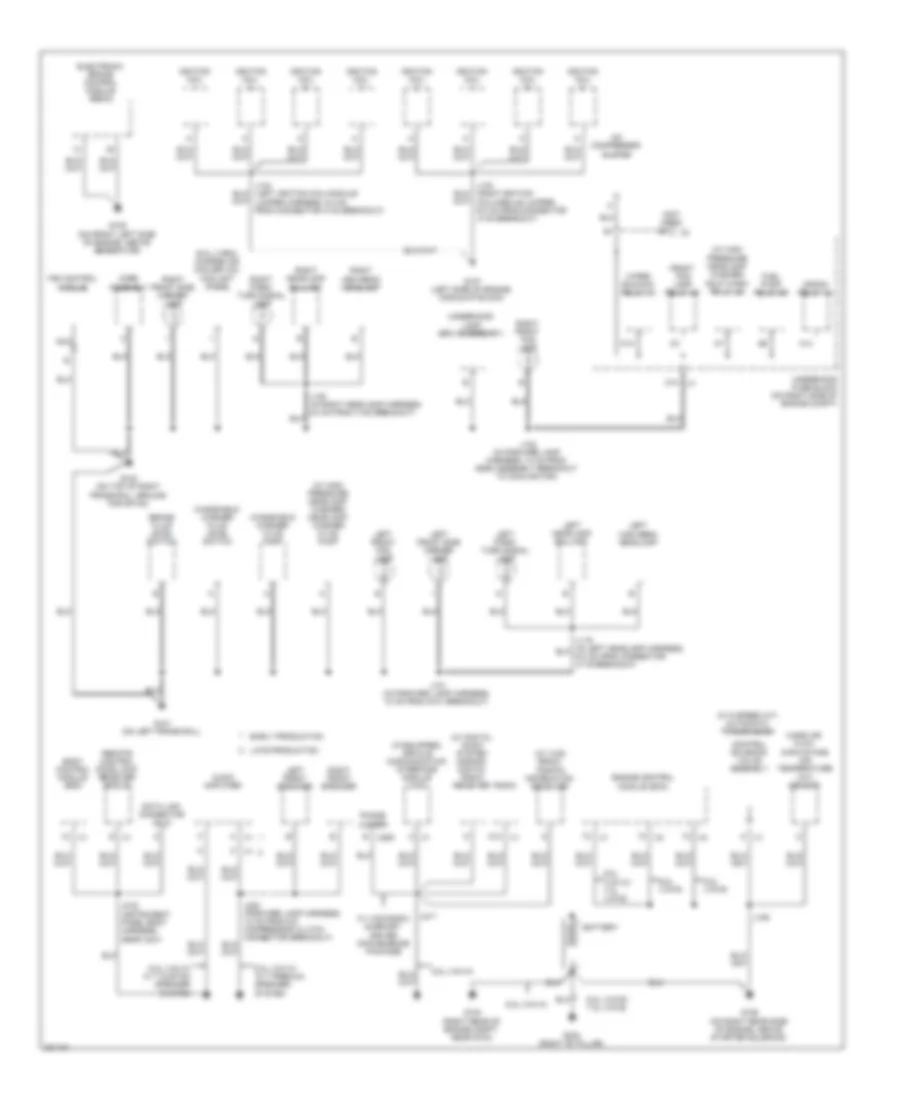
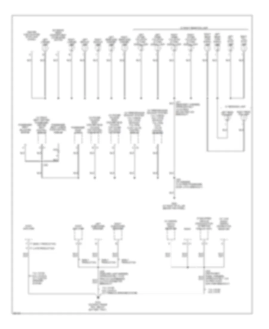
GROUND DISTRIBUTION
Ground Distribution Wiring Diagram (1 of 4) for Chevrolet Corvette 2009
List of elements for Ground Distribution Wiring Diagram (1 of 4) for Chevrolet Corvette 2009:
- (6.2l (virn)) charge air cooler (ac) coolant pump
- (if equipped) vehicle communication interface module (vcim)
- (not used)
- (w/ 6 speed a/t) automatic transmission
- (w/ digital audio system s-band) digital radio receiver
- (w/ high pressure headlamp washer) hdlp wash relay 46
- (w/ high pressure headlamp washer) headlamp washer fluid pump
- (w/ vics radio) traffic information receiver
- 6.2l (vin r)
- 6.2l (vin r)/ 7.0l (vin e)
- 6.2l (vin w)
- 6.2l (vin w) w/ 7 custom speaker system
- 6.2l (vin w) w/ 7 premium speaker system
- 6.2l (vin w)/ 7.0l (vin e)
- A x1
- A/c compressor clutch
- A12 x1
- A14
- Audio amplifier
- Battery
- Body control module (bcm)
- Brake fluid level switch
- C10
- Control solenoid valve assembly
- Crank relay 43
- Data link connector (dlc)
- E x285
- Early production
- Electronic brake control module (ebcm)
- Engine control module (ecm)
- Fan control module
- Front fog lamp relay 38
- Fuel pump relay 55
- G101 (on left frame rail)
- G102 (on top of right frame rail, ground for sp102)
- G103 (right rear of engine compt, near g104)
- G105 (on front left side of engine, above generator)
- G106 (on right rear side of engine, above starter solenoid)
- G107 (left side of engine, middle of block)
- G303 (right "b" pillar)
- Horn assembly
- Ignition coil
- J101 (in forward lamp harness, 10 cm from g101 breakout)
- J102 (in forward lamp harness, 10 cm from horn assembly breakout to cooling fan)
- J106
- J217
- J232 (instrument panel body harness, near x231)
- Late production
- Left front fog lamp
- Left front side marker lamp
- Left front speaker
- Left headlamp ballast
- Left high beam headlamp
- Left park/ turn signal lamp
- M14
- Mass air flow (maf)/intake air temperature (iat) sensor
- Nca
- Phone jumper
- Radio
- Remote control door lock receiver (rcdlr)
- Right front fog lamp
- Right front side marker lamp
- Right front speaker
- Right headlamp ballast
- Right high beam headlamp
- Right park/ turn signal lamp
- S x1
- Underhood fuse block (on right side of engine compt)
- Underhood lamp (spo accessory)
- W/ vics radio & memory driver convenience package
- Windshield washer fluid level switch
- Windshield washer fluid pump
- Wiper run/acc relay 42
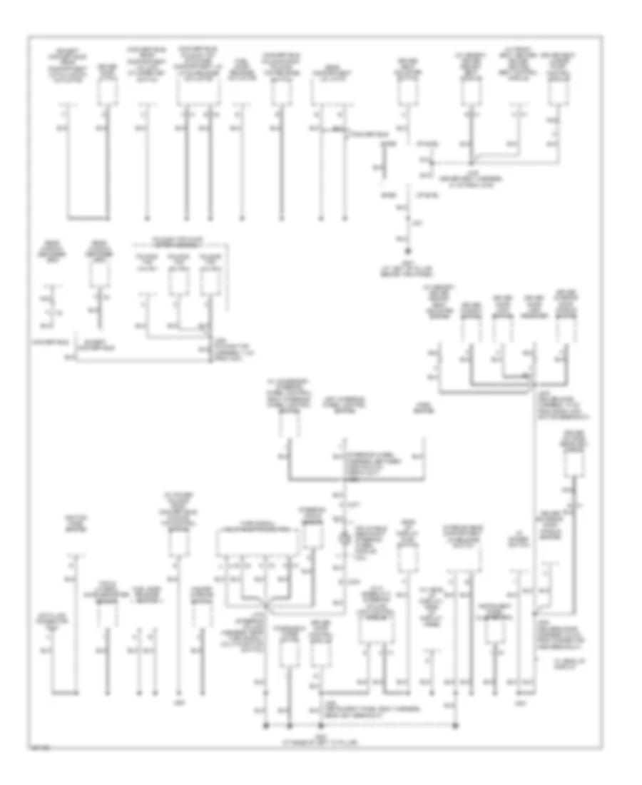
Ground Distribution Wiring Diagram (2 of 4) for Chevrolet Corvette 2009
List of elements for Ground Distribution Wiring Diagram (2 of 4) for Chevrolet Corvette 2009:
- (convertible folding roof) folding top release switch
- (convertible) folding top stowage compartment lid latch release actuator
- (convertible) rear compartment lid lock cylinder key switch
- (except convertible) rear compartment lid pulldown actuator
- (w/ 6 speed a/t) steering column lock control module
- (w/ accessory, steering wheel control) right steering wheel control switch
- (w/ front seat heater) driver heated seat control module
- (w/ head up display) head up display (hud)
- (w/ memory) driver memory seat adjuster switch
- (w/ memory) driver memory seat module
- (w/ power folding roof- convertible) folding top control switch
- A x2
- B x1
- B x2
- Base
- Convertible
- Data link connector (dlc)
- Driver door control module
- Driver door latch
- Driver door lock indicator
- Driver door lock switch
- Driver exterior door handle switch
- Driver interior door handle switch
- Driver outside rearview mirror
- Driver seat adjuster switch
- Driver seat lumbar pump/ control module
- Driver window switch
- Except convertible
- Folding top pump/ motor assembly
- Folding top valve 1
- Folding top valve 2
- Folding top valve 3
- Fuel door release actuator
- Fuel door release switch
- G x4
- G201 (at base of left "a" pillar)
- G301 (at left "b" pillar, behind trim panel)
- Hazard warning switch
- Head up display (hud) switch
- Horn switch
- I/p dimmer switch
- Ignition mode switch
- Inflatable restraint steering wheel module coil
- Instrument panel cluster (ipc)
- Interior rear compartment lid release switch
- J200
- J275 (steering column harness, near turn signal/ multi-function switch)
- J301
- J303
- J379 (driver seat harness, 21 cm from x375)
- J539 (drivers door harness, 6.5 cm from connector x555 breakout)
- J579 (driver door harness, 10 cm from door lock switch breakout)
- K x1
- K x3
- Left steering wheel control switch
- Nca
- Near x501 breakout)
- Rear compartment lid latch
- Rear window defogger grid
- Steering angle sensor
- Turn signal/ multi-function switch
- Uplevel
- W/ head up display
- Windshield wiper motor
- X1 b
- X276 b
- X277
- Yaw & lateral accelerometer sensor
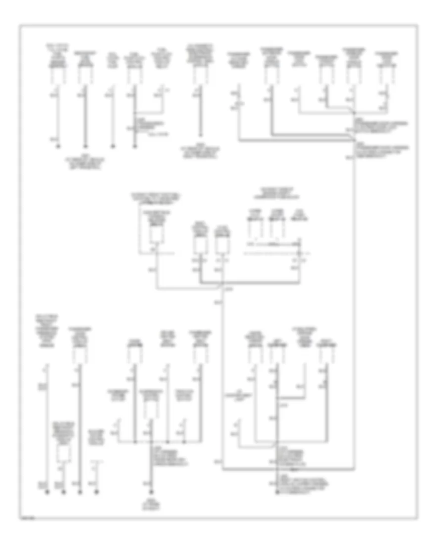
Ground Distribution Wiring Diagram (3 of 4) for Chevrolet Corvette 2009
List of elements for Ground Distribution Wiring Diagram (3 of 4) for Chevrolet Corvette 2009:
- (6.2l (vin r)) fuel pump
- (6.2l (vin w)/ 7.0l (vin e)) fuel pump & sender assembly
- (convertible) tonneau release relay
- (if equipped) garage door opener (gdo)
- (in right front footwell, mounted to toe board) i/p relay block
- (on right side of engine compt) underhood fuse block
- (w/ magnetic ride control) electronic suspension control (esc) module
- 6.2l (vin r)
- Accessory power outlet
- B x1
- Blower motor control module
- Body control module (bcm)
- Cigar lighter
- D1 x3
- Driver heated seat switch
- Fuel pump flow control module
- Fuel pump flow control module relay
- G202 (at base of right)
- G401 (at rear of vehicle, on inner side of left frame rail)
- G402 (at rear of vehicle, on inner side of right frame rail)
- Hvac control module
- I/p compartment lamp
- Inflatable restraint front passenger presence system (pps) module
- Inflatable restraint sensing & diagnostic module (sdm)
- Inside rearview mirror (isrvm)
- J202 (right ignition control module jumper harness, 5.0 cm from connector x110 breakout)
- J216
- J246 (i/p harness, 39.5 cm from inside rearview mirror breakout)
- J315
- J640
- Left sunshade
- M10
- M18
- Nca
- Passenger door control module (pdm)
- Passenger door lock indicator
- Passenger door lock switch
- Passenger exterior door handle switch
- Passenger heated seat switch
- Passenger interior door handle switch
- Passenger outside rearview mirror
- Passenger window switch
- Right sunshade
- Secondary fuel level sensor
- Suspension control switch
- Traction control switch
- W/s wash relay 36
- Wiper hi/lo relay 41
- Wiper on/off relay 45
- X1 a1
- X4 e12
Ground Distribution Wiring Diagram (4 of 4) for Chevrolet Corvette 2009
List of elements for Ground Distribution Wiring Diagram (4 of 4) for Chevrolet Corvette 2009:
- (early production)
- (if equipped) vehicle communication interface module (vcim)
- (late production)
- (w/ front seat heater) passenger heated seat control module
- (w/ performance exhaust system/ 7.0l (vine e)/ 6.2l (vin r) exhaust tail pipe flow valve control module
- (w/ performance exhaust system/ 7.0l (vine e)/ 6.2l (vin r) exhaust tail pipe flow valve control solenoid
- (w/ power folding roof- convertible) folding top control module (ftm)
- (w/ power folding roof- convertible) folding top cover pulldown actuator
- (w/ s-band) digital radio receiver
- (w/ vcis radio) traffic information receiver
- 7.0l (vin e)/ 6.2l (vin r)
- 7.0l (vin e)/ 6.2l (vin r) & w/ 7 custom speaker system
- 7.0l (vin e)/ 6.2l (vin r) & w/ 7 premium speaker system
- Audio amplifier
- Center high mounted stop lamp (chmsl)
- Early production
- Exterior rear compartment lid release switch
- F x1
- G104 (on right frame rail, below battery tray)
- G302 (at right "b" pillar, behind trim panel)
- J302 (i/p harness, 10 cm from passenger door latch breakout)
- J382
- Left backup lamp
- Left inner tail/stop & turn signal lamp
- Left license lamp
- Left outer tail/stop & turn signal lamp
- Left rear fog lamp
- Left rear side marker lamp
- Left rear turn signal lamp
- Left subwoofer speaker
- Left tail/ stop lamp
- Nca
- Passenger door latch
- Passenger seat adjuster switch
- Passenger seat lumbar pump/control module
- Radio
- Right backup lamp
- Right inner tail/stop & turn signal lamp
- Right license lamp
- Right outer tail/stop & turn signal lamp
- Right rear fog lamp
- Right rear side marker lamp
- Right rear turn signal lamp
- Right subwoofer speaker
- Right tail/ stop lamp
- W/ rear fog lamp
- W/ right rear fog lamp
- X1 a
- X1 a12
- X1 b
- X1 k
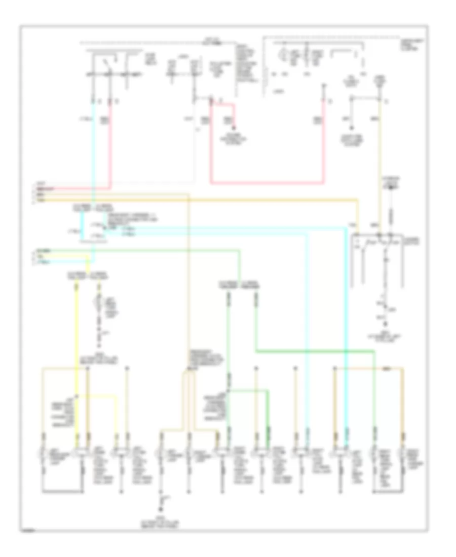
HEADLIGHTS
Headlights Wiring Diagram for Chevrolet Corvette 2009
List of elements for Headlights Wiring Diagram for Chevrolet Corvette 2009:
- (in right front footwell, mounted to toe board) i/p relay block
- (not used)
- (rear body harness, approximately 6.5 cm from left backup lamp connector breakout) j472
- Air conditioning system
- Auto
- Body control module (bcm) (mounted on toe board, in right footwell)
- C10
- Class 2 (bcm)
- Class 2 ser data
- Computer data lines system
- D10
- F11
- Fog lamp ind
- Fog lmp rly ctrl
- Front fog
- Front fog lmp sw sig
- Frt fog lp fuse 22 15a
- Frt fog lp relay 38
- Ftp
- Ftp sw sig
- G101 (on left frame rail)
- G102 (on top of right frame rail, ground for sp102)
- G201 (at base of left "a" pillar)
- G302 (at right "b" pillar, behind trim panel)
- Head
- Headlamp on sig
- Hi beam sig
- Hi bm rly ctrl
- High
- High beam ind
- High beam relay
- Hot at all times
- Hvac control module (center of dash, under radio)
- Instrument panel cluster (ipc)
- J101
- J102
- J119
- J120
- J242 (i/p harness, 35 cm from hvac control module connector)
- J275
- J471
- Lamp switch
- Left front fog lamp
- Left headlamp assembly
- Left headlamp ballast
- Left high beam headlamp
- Left rear fog lamp
- Logic
- Low
- Low beam relay
- Low bm rly ctrl
- Low ref
- Lt hi bm fuse 24 10a
- Lt lo bm fuse 21 20a
- Nca
- Off
- Park
- Prk lmp sw off sig
- Prk lmp sw on sig
- Rear fog lamp switch
- Rear fog lmp rly ctrl
- Rear fog lmp sw sig
- Rear fog/ aldl/top switch fuse 10a
- Rear/fog relay (if equipped)
- Right front fog lamp
- Right headlamp assembly
- Right headlamp ballast
- Right high beam headlamp
- Right rear fog lamp
- Rt hi bm fuse 23 10a
- Rt lo bm fuse 19 20a
- Sen sig
- Ser data
- Ser data class 2
- Sunload sensor assembly (on top left center of dash)
- Turn signal/ multi-function switch
- Underhood fuse block (on right side of engine compt)
HORN
Horn Wiring Diagram for Chevrolet Corvette 2009
List of elements for Horn Wiring Diagram for Chevrolet Corvette 2009:
- A x276
- A10 x1
- A12 x3
- Body control module (bcm) (mounted on toe board, in right footwell)
- G102 (on top of right frame rail, ground for sp102)
- G201 (at base of left "a" pillar)
- Horn assembly (right front of engine compt)
- Horn relay 34
- Horn rly ctrl
- Horn switch
- Horn/alt sense fuse 2 15a
- Hot at all times
- Inflatable restraint steering wheel module coil (center of steering column)
- J102
- J292
- Logic
- Tan
- Underhood fuse block (on right side of engine compt)
- X277
INSTRUMENT CLUSTER
Instrument Cluster Wiring Diagram (1 of 2) for Chevrolet Corvette 2009
List of elements for Instrument Cluster Wiring Diagram (1 of 2) for Chevrolet Corvette 2009:
- (at base of left "a" pillar) g201
- (left side of dash) head up display (hud) switch
- A12
- A13
- A14
- A16
- Abs ind
- Air bag ind
- Ajar
- B14
- B15
- B16
- Bat + voltage
- Brake fluid level switch (in master cylinder reservoir)
- Brake ind
- Brk fluid lvl sens sig
- Charging gauge
- Class 2 (bcm)
- Class 2 (ecm)
- Class 2 (sdm)
- Closed
- Computer data lines system
- Coolant temp gauge
- Dic fuel sw sig
- Dic gauges sw sig
- Dic option sw sig
- Dic reset sw sig
- Dic trip sw sig
- Dome lmp sw sig
- Door ajar sw
- Driver door latch (in rear of driver door)
- Driver information center (dic)
- Driver information center (dic) switch
- Eng spd sig
- Engine speed sig
- Exterior lights system
- Fog lamp ind
- Front passenger door latch (in rear of passenger door)
- Fuel level gauge
- Fuel switch
- G101 (on left frame rail)
- G201 (at base of left "a" pillar)
- G301 (at left "b" pillar, behind trim panel)
- G302 (at right "b" pillar, behind trim panel)
- Gauges switch
- Gmlan (ebcm)
- Gmlan (ecm)
- Gnd
- Haz flasher sig
- High beam ind
- Hud dim dn
- Hud dim up
- Hud dn
- Hud up
- I/p dim sw dn sig
- I/p dim sw up sig
- I/p lmp dim ctrl
- I/p lmp sply voltage 2
- Ign
- Illum
- Illumination (3 bulbs)
- Inst panel lmp sply volt
- Instrument panel cluster (ipc)
- Interior lights system
- Ipc
- Ipc class 2 serial data
- J101
- J301
- J302
- J303
- Km/h ind
- Lamp outage ind
- Left turn ind
- Logic
- Low ref
- Low tire pressure ind
- Malfunction ind
- Mode
- Mph ind
- Oil level gauge
- Oil temp sens sig
- Open
- Option switch
- Page
- Park brake switch (lower front of park brake handle)
- Pnk
- Prk brk sw sig
- Prk lmp sply voltage
- Reset switch
- Right turn ind
- Rpm x 1000 gauge
- Seat belt ind
- Security ind
- Speedometer
- Tan
- Traction off ind
- Trip switch
- Turn signal audible ind
- Underhood fuse block (on right side of engine compt) x1
- Upshift ind
- Veh spd sig
- Vehicle speed sig
- W/w fluid lvl sens sig
- Wiper/washer system
- X1 (conn a)
- X2 (conn b)
Instrument Cluster Wiring Diagram (2 of 2) for Chevrolet Corvette 2009
List of elements for Instrument Cluster Wiring Diagram (2 of 2) for Chevrolet Corvette 2009:
- (at left "b" pillar, behind trim panel) g301
- (driver seat harness, 10 cm from seat belt switch)
- (fuel level sensor right harness, 20 cm from connector x460 breakout) j462
- (right ignition control module jumper, 4.0 cm from breakout to ignition coil/module 4)
- (top left side of dash) (if equipped) head up display (hud)
- 5v ref 1
- 6.2l (vin n) & 7.0l (vin e)
- 6.2l (vin r)
- Bat pos voltage
- Belt switch
- Body control module (bcm) (mounted on toe board, in right footwell)
- Class 2 ser data
- Clstr/ hud fuse 15a
- Computer data lines system
- Convertible
- Coupe
- D10
- Data sig
- Dim up sig
- Dr ajar sw sig
- Driver seat belt buckle
- Driver seat belt switch
- Ect sig
- Eng speed
- Engine control module (ecm) (6.2l except s/charged & 7.0l: behind right front fender, between wheelhouse & dash panel) (6.2l s/charged: right side of engine compt)
- Engine controls system
- Engine coolant temperature (ect) sensor (in front left side of left cylinder head)
- Engine oil level & temperature sensor (6.2l (vin w)) (on bottom right center of engine oil pan)
- Engine oil pressure (eop) sensor (6.2l: on top center rear of engine) (7.0l: on top rear of engine)
- Engine oil temperature sensor (7.0l) (on bottom of oil tank)
- Engine spd sig
- From data link connector breakout)
- Fuel level sensor (left)
- Fuel lvl 2
- Fuel lvl sig
- Fuel pump & sender assembly (in left fuel pump assembly)
- G201 (at base of left "a" pillar)
- G401 (at rear of vehicle, on inner side of left frame rail)
- Gnd
- Hot at all times
- Image dn sig
- Image down
- Image up
- Inflatable restraint sensing & diagnostic module (sdm) (behind center of dash, under hvac control head)
- J211
- J221 (i/p harness, 8 cm pnk
- J301
- J303
- J391
- J400
- J460 (transmission harness, 20 cm from connector x420 breakout)
- Logic
- Low ref
- Lvl sw sig
- Mil ctrl
- Nca
- Oil press
- Page sig
- Pnk
- Radio
- Rear compartment lid latch
- Rear compartment lid pulldown actuator (center rear of compt lid)
- Secondary fuel level sensor (in right fuel tank)
- Serial data
- Serial data+
- Serial data-
- Sig dim dn
- Sig image up
- Tan
- Trk ajar sw sig
- Underhood fuse block (on right side of engine compt)
- Vehicle spd sig
- Vss
INTERIOR LIGHTS
Courtesy Lamps Wiring Diagram for Chevrolet Corvette 2009
List of elements for Courtesy Lamps Wiring Diagram for Chevrolet Corvette 2009:
- (i/p harness, 10 cm from blower motor control module breakout) j310
- (i/p harness, 10 cm from flood lamp breakout) j351
- (transmission harness, 11 cm from yaw rate connector) j422
- A10
- Ajar
- Battery+
- Body control module (bcm) (mounted on toe board, in right footwell)
- Close
- Computer data lines system
- Convertible
- Coupe
- Courtesy lmp
- Courtesy v+
- Ctsy lamps +v
- Ctsy/ lamp fuse 10a
- Dome
- Dome switch
- Driver door latch (in rear of driver door)
- Front passenger door latch (in rear of passenger door)
- G102 (on top of right frame rail, ground for sp102)
- G201 (at base of
- G202 (at base of
- G301 (at left "b" pillar, behind trim panel)
- G302 (at right "b" pillar, behind trim panel)
- Garage door opener (gdo)
- Gnd
- Ground
- Hot at all times
- I/p comp- artment lamp
- I/p dimmer switch
- Inside rearview mirror
- Instrument panel cluster (ipc)
- J102
- J301
- J302
- J303
- J312
- J314
- Left "a" pillar)
- Left i/p courtesy lamp
- Left rear compart- ment courtesy lamp
- Left sunshade
- Lf door ajar
- Logic
- Open
- Rear compartment lid ajar switch
- Rear compartment lid latch
- Rear compartment lid pulldown actuator (center rear of compt lid)
- Rf door ajar
- Right i/p courtesy lamp
- Right rear compartment courtesy lamp
- Right sunshade
- Right)
- Serial data
- Trunk ajar
- Trunk ajar sw sig
- Trunk lamp ctrl
- Underhood fuse block (on right side of engine compt)
- Underhood lamp (spo accessory)
- X1 d2
- X3 b1
Instrument Illumination Wiring Diagram for Chevrolet Corvette 2009
List of elements for Instrument Illumination Wiring Diagram for Chevrolet Corvette 2009:
- (center of steering column) inflatable restraint steering wheel module coil
- (driver door harness, 10 cm from door lock indicator breakout) j559
- (i/p harness, 22.5 cm from inside rearview mirror breakout) j237
- (i/p harness, 5 cm from blower motor control module connector breakout) j255
- (if equipped) folding top control switch
- (if equipped) head up display (hud) switch
- (in i/p harness, 25 cm from dimmer switch breakout)
- (left side of dash)
- (passenger door harness, 10 cm from door lock indicator) j660
- Auto
- Automatic transmission shift lever (a/t)
- Battery
- Battery+
- Body control module (bcm) (mounted on toe board, in right footwell)
- Btsi sol/str whl lck fuse 10a
- C11
- C12 x4
- Clstr/ hud fuse 15a
- Computer data
- Computer data lines system
- Ctsy/ lamp fuse 10a
- D10
- Dic ground
- Dic sw illum
- Dimmer down
- Dimmer up
- Dome sw
- Dome switch
- Driver door control module (bottom center of driver door)
- Driver door lock switch
- Driver heated seat switch
- Driver information center (dic) switch
- Driver interior door handle switch (in center of driver door panel)
- Driver memory seat adjuster switch
- Driver window switch
- Fuel door release switch
- G201 (at base of left "a" pillar)
- G202 (at base of right)
- Ground
- Hazard warning switch
- Head
- Hot at all times
- Hvac control module (center of dash, under radio)
- I/p dimmer switch
- Ignition mode switch
- Illum
- Illum (3 bulbs)
- Instrument panel cluster (ipc)
- J200
- J201
- J275
- J291
- J292
- J303
- J579
- J680
- Lcd backlight
- Left steering wheel control switch
- Lines system
- Logic
- Nca
- Off
- Panel lamps
- Panel lmp ctrl
- Panel lmps
- Park
- Park lamp
- Park lamp relay 37
- Park lamps
- Park sig
- Passenger door control module (bottom center of passenger door)
- Passenger door lock switch
- Passenger heated seat switch
- Passenger interior door handle switch (in center of passenger door panel)
- Passenger window switch
- Pk lamps fuse 8 10a
- Power distribution system
- Radio
- Rear comp- artment release switch (interior)
- Right steering wheel control switch
- Serial data
- Suspension control switch
- Swc dm fuse 2a
- Tan
- Traction control switch
- Turn signal/ multi-function switch
- Underhood fuse block (on right side of engine compt)
MEMORY SYSTEMS
Driver"s Memory Seat Wiring Diagram (1 of 2) for Chevrolet Corvette 2009
List of elements for Driver"s Memory Seat Wiring Diagram (1 of 2) for Chevrolet Corvette 2009:
- 5 volt reference
- A10
- A11
- A12
- A13
- A14
- A15
- A16
- B10
- B11
- B12
- B13
- B14
- B15
- B16
- Battery positive voltage
- Body control module (bcm) (mounted on toe board, in right footwell)
- Class 2 serial data
- Column telescope forward control
- Column telescope forward sw
- Column telescope reverse control
- Column telescope reverse sw
- Column telescope sensor sig
- Computer data lines system
- Driver 1
- Driver 2
- Driver memory seat adjuster switch
- Driver memory seat module (under center of drivers seat)
- Driver window switch
- Exit switch
- Front vertical down switch signal
- Front vertical motor down control
- Front vertical motor up control
- Front vertical position sens
- Front vertical up switch signal
- G201 (at base of left "a" pillar)
- G301 (at left "b" pillar, behind trim panel)
- Ground
- Horizontal forward switch signal
- Horizontal motor forward ctrl
- Horizontal motor rearward control
- Horizontal position sens
- Horizontal rearward switch signal
- Hot at all times
- I/p fuse block (in right front footwell, mounted to toe board)
- Illum
- Interior lights system
- J379 (up level)
- J393
- J579
- Logic
- Low reference
- Memory 1 switch sig
- Memory 2 switch sig
- Pnk
- Power distribution system
- Pwr seats msm circuit breaker 30a
- Rear vertical down switch signal
- Rear vertical motor down control
- Rear vertical motor up control
- Rear vertical position sens
- Rear vertical up switch signal
- Steering column memory circuit
- Tan
- Tele swtch/ msm fuse 10a
Driver"s Memory Seat Wiring Diagram (2 of 2) for Chevrolet Corvette 2009
List of elements for Driver"s Memory Seat Wiring Diagram (2 of 2) for Chevrolet Corvette 2009:
- Driver seat adjuster motor assembly
- Driver seat adjuster switch
- Driver seat front vertical motor position sensor
- Driver seat horizontal motor position sensor
- Driver seat rear vertical motor position sensor
- Front down
- Front up
- Front vertical motor
- Horizontal forward
- Horizontal motor
- Horizontal rearward
- J395 (driver seat harness, 4 cm from lumbar pump/control module assembly breakout)
- J397 (driver seat harness, 5 cm from seat adjuster motor assembly breakout)
- Nca
- Rear down
- Rear up
- Rear vertical motor
- Steering column telescope actuator
- Tan
Memory Mirrors Wiring Diagram for Chevrolet Corvette 2009
List of elements for Memory Mirrors Wiring Diagram for Chevrolet Corvette 2009:
- 5v reference
- Battery b+
- Class 2 serial data
- Computer data lines system
- Down directional sw
- Driver 1
- Driver 2
- Driver door control module (bottom center of driver door)
- Driver memory seat adjuster switch
- Driver outside rearview mirror
- Driver window switch
- Exit switch
- G201 (at base of left "a" pillar)
- G202 (at base of right)
- Ground
- Horiz posit sensor
- Horizontal motor
- Horizontal position sensor
- Hot at all times
- I/p fuse block (in right front footwell, mounted to toe board)
- Illum
- Interior lights system
- J234
- J579
- Left directional sw
- Left mirror select
- Logic
- Low reference
- Memory 1 sw sig
- Memory 2 sw sig
- Mirror mtr down ctrl
- Mirror mtr left ctrl
- Mirror mtr right ctrl
- Mirror mtr up ctrl
- Nca
- Passenger door control module (bottom center of passenger door)
- Passenger outside rearview mirror
- Pwr/wndws trunk/fuel relse circuit breaker 30a
- Right directional sw
- Right mirror select
- Tan
- Up directional sw
- Vertical motor
- Vertical posit sensor
- Vertical position sensor
Steering Column Memory Wiring Diagram for Chevrolet Corvette 2009
List of elements for Steering Column Memory Wiring Diagram for Chevrolet Corvette 2009:
- (driver seat harness, 4 cm from lumbar pump/control module assembly breakout)
- 5 volt reference
- A10
- A13
- A15
- B15
- Battery b+
- Body control module (bcm) (mounted on toe board, in right footwell)
- Class 2 serial data
- Computer data lines system
- Driver 1
- Driver 2
- Driver memory seat adjuster switch
- Driver memory seat module (under center of drivers seat)
- Driver window switch
- Exit switch
- G201 (at base of left "a" pillar)
- G301 (at left "b" pillar, behind trim panel)
- Ground
- Hot at all times
- I/p fuse block (in right front footwell, mounted to toe board)
- Illum
- Interior lights system
- J379 (up level)
- J395
- J397 (driver seat harness, 5 cm from seat adjuster motor assembly breakout)
- J579
- Logic
- Low reference
- Memory 1 switch sig
- Memory 2 switch sig
- Memory seats circuit
- Nca
- Pnk
- Power distribution system
- Pwr seats msm circuit breaker 30a
- Steering column telescope motor
- Steering column telescope position sensor
- Steering column telescope switch
- Tan
- Tele sw/msm fuse 10a
- Telescope forward ctrl
- Telescope forward sig
- Telescope in
- Telescope out
- Telescope reverse ctrl
- Telescope reverse sig
- Telescope sensor sig
NAVIGATION
Navigation Wiring Diagram for Chevrolet Corvette 2009
List of elements for Navigation Wiring Diagram for Chevrolet Corvette 2009:
- (in instrument panel harness, 7.5 cm (6.9 in) front folding top 5 bow switches breakout)
- (or nca)
- A12
- Battery
- Body control module (bcm) (mounted on toe board, in right footwell)
- Cellular telephone microphone (upper left ``a" pillar)
- Class 2 serial data
- Coax
- Computer data lines system
- Drain
- Drain wire
- G103 (6.2l (vin w)) (right rear of engine compt, near g104)
- G104 (7.0l & 6.2l (vin r)) (on right frame rail, below battery tray)
- Ground
- Hot at all times
- J217 (6.2l (vin w)) j223 (7.0l & 6.2l (vin r))
- J308 (in instrument panel harness, 24 cm (9 in) from center console flood lamp breakout)
- J309
- J311
- J316 (in instrument panel harness) nca
- J317
- Low ref drain
- Microphone sig
- Navigation antenna
- Nca
- Pnk
- Radio
- Rdo/ s-band/ vics fuse 15a
- Rec aud sig
- Rec low ref
- Signal
- Vehicle communication interface module (vcim) (if equipped) (in right rear compt)
- Voice rec aud sig
- W/ communication system
- W/o communication system
POWER DISTRIBUTION
Power Distribution Wiring Diagram (1 of 4) for Chevrolet Corvette 2009
List of elements for Power Distribution Wiring Diagram (1 of 4) for Chevrolet Corvette 2009:
- (6 cm from ebcm breakout) j195
- (on right side of engine compt) underhood fuse block
- 6.2l (vin w)/ 7.ol
- A x1
- A/c comp fuse 15 10a
- A/c comp relay 35
- A18
- A19
- Abs fuse 11 25a
- Abs fuse 27 40a
- Amp fuse 31 30a
- Audio amplifier
- Automatic transmission (a/t)
- Base
- Batt 1 fuse 33 60a
- Batt 2 fuse 29 30a
- Battery
- Blower motor control module
- C14
- Coolfan fuse 25 60a
- Crank relay 43
- Driver door control module
- Driver heated seat module (w/ front heated seats)
- Driver memory seat module (w/ memory)
- Driver seat adjuster switch (w/o memory)
- Driver seat lumbar pump/ control module
- Driver seat lumbar switch
- Drvr htd seat fuse 20a
- E x1
- Ecm/tcm/easy key fuse 56 15a
- Electronic brake control module (ebcm)
- Electronic suspension control (esc) module (w/ magnetic ride control)
- Engine control module (ecm)
- Evaporative emission (evap) canister vent solenoid valve
- F12 x3 x2
- Fan control module
- Folding top control module (w/ power folding roof)
- Frt fog lp fuse 22 15a
- Frt fog lp relay 38
- Fuel dr relse relay
- Fuel pump fuse 20 20a
- Fuel pump relay 55 (except 6.2l vin r)
- Generator
- H x1
- H13
- H14
- Hdlp wash fuse 18 20a
- Hdlp wash relay 46
- High beam relay 39
- Horn relay 34
- Horn/ alt sense fuse 2 15a
- Hvac fuse 28 40a
- I/p fuse block (in right front footwell, mounted to toe board)
- I/p relay block (in right front footwell, mounted to toe board)
- J203
- J234 (11.5 cm from the main harn, leading to pcm)
- J399
- K10
- K14
- Left front speaker
- Low beam relay 47
- Mrrtd fuse 13 25a
- Nca
- Park/pos lamp relay 37
- Pass htd seat fuse 20a
- Passenger door control module
- Passenger heated seat module (w/ front heated seats)
- Passenger seat adjuster switch (if equipped)
- Passenger seat lumbar pump/ control module
- Passenger seat lumbar switch
- Pk lamps fuse 8 10a
- Powertrain ign 1 relay 44
- Premium
- Prw/wndws trunk/fuel relse circuit breaker 30a
- Pwr seats msm circuit breaker 30a
- Rear defog relay 40
- Red
- Remote control door lock receiver (rcdlr)
- Reverse lockout solenoid (m/t)
- Right front speaker
- Starter fuse 30 40a
- Starter motor
- To batt 3 fuse 26 (diagram 2 of 4)
- To i/p fuse block (diagram 3 of 4)
- W/s wash fuse 17 15a
- W/s wash relay 36
- Wiper fuse 4 30a
- Wiper on/off relay 45
- Wiper run/acc relay 42
- X2 d11
- X3 d5
- X4 a2
- X4 b1
Power Distribution Wiring Diagram (2 of 4) for Chevrolet Corvette 2009
List of elements for Power Distribution Wiring Diagram (2 of 4) for Chevrolet Corvette 2009:
- (39 cm from the hvac control module connector) j231
- (5.0 cm from connector x109 breakout) j208
- (a/t)
- (mounted on toe board, in right footwell) body control module (bcm)
- A6 x3
- A8 x2
- A8 x3
- Automatic transmission shift lever (a/t)
- B x1
- B1 x1
- B11 x3
- Batt 3 fuse 26 60a
- Bck/up lamp relay
- Btsi sol/str whl lck fuse 10a
- C1 x4
- Clstr/hud fuse 15a
- Cruise swtch fuse 2a
- Ctsy/ lamp fuse 10a
- D1 x3
- D10
- D4 x3
- D8 x4
- Data link connector (dlc)
- Digital radio receiver
- Diode
- Dr lck fuse 15a
- Driver door unlatch pcb relay
- Driver heated seat control module (w/ front heated seats)
- E10 x4
- E11 x3
- Ex mdl fuse 10a
- Exhaust tail pipe flow valve control module (7.0l/ 6.2l (vin r))
- F19
- F4 (not used)
- F5 x4
- F6 x4
- Folding top control switch (w/ power folding roof)
- From batt 1 fuse (diagram 1 of 4)
- G19
- Head up display (hud) (if equipped)
- Htd seat/ wpr rly fuse 10a
- Hvac control module
- Hvac/ pwr snd fuse 10a
- I/p relay block (in right front footwell, mounted to toe board)
- Inadvertent load control pcb relay
- Inflatable restraint steering wheel module coil
- Inside air temperature sensor
- Inside rearview mirror (isrvm)
- Instrument panel cluster (ipc)
- Isrvm/ hvac fuse 10a
- K15
- Lamp
- Left automatic transmission manual shift switch
- Logic
- Nca
- Passenger door unlatch pcb relay
- Passenger heated seat control module (w/ front heated seats)
- Pnk
- Radio
- Rdo/s-band/ vics fuse 15a
- Rear fog/ aldl/top swtch fuse 10a
- Rear/fog relay
- Rly ctrl
- Run crnk relay
- Steering column lock control module (if equipped)
- Stop lamp relay
- Stop/b/u/ lamps fuse 5 15a
- To batt 5 fuse 7 (diagram 3 of 4)
- To gmlan run/crnk fuse (diagram 3 of 4)
- Tonneau relse fuse 10a
- Tonneau relse relay
- Traffic information receiver
- Turn signal/ multi-function switch
- Underhood fuse block (on right side of engine compt)
- W/ digital radio
- W/ rr fog
- W/o digital radio
- Wiper run/ acc relay 42
- Wiper/ washer system
- X276 c
- X277
- X3 c3
Power Distribution Wiring Diagram (3 of 4) for Chevrolet Corvette 2009
List of elements for Power Distribution Wiring Diagram (3 of 4) for Chevrolet Corvette 2009:
- (in right front footwell, mounted to toe board) i/p fuse block
- (mounted on toe board, in right footwell) body control module (bcm)
- (not used)
- A1 x4
- A11
- Abs/mrrtd fuse 3 10a
- Accessory power outlet
- Automatic transmission (a/t)
- Aux pwr fuse 20a
- B10
- B11 x2
- B12 x3
- B5 x3
- Batt 5 fuse 7 30a
- C10
- C5 x3
- C5 x4
- Cigar lighter
- Coupe
- D11 x3
- D12
- Driv dr switch fuse 10a
- Driver memory seat module (w/ memory)
- Driver seat adjuster switch
- Driver window switch
- E11
- Ecm fuse 15a
- Electronic brake control module (ebcm)
- Electronic suspension control (esc) module
- Engine control module (ecm)
- Except coupe
- F11
- Folding top stowage compartment lidlatch pulldown actuator (w/ power folding roof)
- From batt 1 fuse 33 (diagram 1 of 4)
- From htd seat/ d wpr rly fuse (diagram 2 of 4)
- From stop/ b/u/lamps fuse 5 (diagram 2 of 4)
- G202 (at base of right)
- Gmlan run/crnk fuse 20a
- I/p relay block (in right front footwell, mounted to toe board)
- Ign switch/ intr sens fuse 10a
- Inflatable restraint front passenger presence system (pps) module
- Inflatable restraint sensing & diagnostic module (sdm)
- J139 (in engine harness)
- J246
- J393
- Logic
- Ltr fuse 20a
- Nca
- Onstar fuse 10a
- Pnk
- Rear compartment lid pulldown actuator
- Sdm/aos switch air bag fuse 10a
- Steering column telescope switch (if equipped)
- Tcm/trans fuse 1 10a
- Tele switch/msm fuse 10a
- To ignition mode switch (diagram 4 of 4)
- Tpa fuse 20a
- Trunk relse fuse 15a
- Trunk relse relay
- Underhood fuse block (on right side of engine compt)
- Vehicle communication interface module (vcim) (w/ onstar)
- W/ magnetic ride control
Power Distribution Wiring Diagram (4 of 4) for Chevrolet Corvette 2009
List of elements for Power Distribution Wiring Diagram (4 of 4) for Chevrolet Corvette 2009:
- Acc ind
- Acc ind ctrl
- Back up sig
- Backup keyless entry antenna
- Body control module (bcm) (mounted on toe board, in right footwell)
- From body control module (diagram 3 of 4)
- Gnd
- Ign 1 volt
- Ign 1 voltage
- Ign data sig
- Ignition mode switch
- Interior lights system
- Left keyless entry antenna
- Left sig
- Logic
- Low ref
- Mode ctrl
- Mode voltage
- Off
- Off ind
- Off ind ctrl
- Pnk
- Rear compartment keyless entry antenna
- Remote control door lock receiver (rcdlr) (right side of dash)
- Right keyless entry antenna
- Right sig
- Sig
- Start
- Start ind
- Start ind ctrl
- Tan
POWER DOOR LOCKS
Power Door Locks Wiring Diagram (1 of 2) for Chevrolet Corvette 2009
List of elements for Power Door Locks Wiring Diagram (1 of 2) for Chevrolet Corvette 2009:
- (in i/p harness, left of audio amplifier) splice pack jx208
- (in i/p harness, left of steering column) splice pack jx205
- A/t shft lk ctrl
- Ajar
- Backup keyless entry antenna (right side of dash)
- Battery
- Closed
- D11
- Data link connector (dlc) (under dash, below steering column)
- Door ajar sw
- Door latch
- Door open sw
- Dr lk act ctrl
- Driver door latch (in rear of driver door)
- Dvr dr lk act
- Ecm/tcm/ easy key fuse 11 15a
- Exterior lights system
- Front passenger door latch (in rear of passenger door)
- G103 (right rear of engine compt, near g104)
- G301 (at left "b" pillar, behind trim panel)
- G302 (at right "b" pillar, behind trim panel)
- Ground
- Hot at all times
- Ign 1 volt
- Ign mod data
- Ignition mode switch
- J232
- J301
- J302
- K/e ant b-u sig
- K/e b-u low ref
- K/e left low ref
- K/e left sig
- K/e rear compt sig
- K/e right sig
- K/e rt low ref
- Left frnt int dr
- Left keyless entry antenna (top of left "b" pillar)
- Lf frt ext dr
- Open
- Pnk
- Rear compartment keyless entry antenna (below rear compt pull down actuator)
- Rear compt lo ref
- Remote control door lock receiver (rcdlr) (right side of dash)
- Rfa class 2 data
- Right keyless entry antenna (top of right "b" pillar)
- Rt frnt int dr
- Rt frt ext dr
- Shift interlock system
- Tan
- Trunk rel sw sig
- Trunk, tailgate, fuel doors system
- Underhood fuse block (on right side of engine compt)
- X2 a
Power Door Locks Wiring Diagram (2 of 2) for Chevrolet Corvette 2009
List of elements for Power Door Locks Wiring Diagram (2 of 2) for Chevrolet Corvette 2009:
- A1 x3
- Battery
- Body control module (bcm) (mounted on toe board, in right footwell)
- Class 2 (bcm)
- Class 2 data
- Convertible
- Coupe
- Door latch ctrl
- Dr ajar sw sig
- Dr lck fuse 15a
- Dr lock ind
- Dr open sw sig
- Driv dr switch fuse 10a
- Driver door control module (bottom center of driver door)
- Driver door lock indicator (in upper rear of driver door trim panel)
- Driver door lock switch
- Driver door unlatch pcb relay
- Driver exterior door handle switch (in upper rear of driver door)
- Driver interior door handle switch (in center of driver door panel)
- Driver window switch
- Exterior lights system
- G201 (at base of left "a" pillar)
- G202 (at base of right "a" pillar)
- Ground
- Handle sw sig
- Horn rel cntrl
- Horns system
- Hot at all times
- Ign
- Ign 1 volt
- Ign switch/ intr snsr fuse 10a
- Instrument panel cluster (ipc)
- Interior lights system
- Ipc class 2 serial data
- J539
- J579
- J640
- J680
- Lcd lamp
- Lock
- Lock cntrl
- Lock sig
- Logic
- Memory 1
- Memory 2
- Memory systems
- Nca
- Passenger door control module (bottom center of passenger door)
- Passenger door lock indicator (in upper rear of passenger door trim panel)
- Passenger door lock switch
- Passenger door unlatch pcb relay
- Passenger exterior door handle switch (in upper rear of passenger door)
- Passenger interior door handle switch (in center of passenger door panel)
- Pk lamp rly
- Pnk
- Rear compartment lid latch
- Rear compartment lid pulldown actuator (center rear of compt lid)
- Security ind
- Serial data
- Tan
- Trk ajar sw sig
- Un- lock
- Unlock cntrl
- Unlock sig
POWER MIRRORS
Automatic Day/Night Mirror Wiring Diagram for Chevrolet Corvette 2009
List of elements for Automatic Day/Night Mirror Wiring Diagram for Chevrolet Corvette 2009:
- (at base of right "a" pillar) g202
- Ambient light sensor ind
- Automatic day/night mirror
- Backup lamp pwr
- Bck/up lamp relay
- Body control module (bcm) (mounted on toe board, in right footwell)
- Button back lighting
- Day/night mirror low ref
- Day/night mirror sig
- Digital radio anteena
- Driver outside rearview mirror
- Emergency ind
- Emergency switch
- Gnd
- Headlight sensor ind
- Hot at all times
- Ign 1 volt
- Inside rearview mirror
- Interior lights system
- Isrvm/ hvac fuse 10a
- J231
- J312
- Keypad green led ind
- Keypad green led sig
- Keypad red led ind
- Keypad red led sig
- Keypad sig
- Keypad sply volt
- Left
- Logic
- Nca
- Onstar button assembly
- Onstar ind
- Onstar switch
- Passenger air bag off ind
- Passenger air bag on ind
- Phone ind
- Phone switch
- Pnk
- Reverse lamp rly ctrl
- Reverse lamps fuse 10a
- Right
- Run crnk relay
- Run/ crank rly ctrl
- Vehicle communication interface module (vcim) (w/ onstar) (in right rear compt)
Power Mirror Wiring Diagram for Chevrolet Corvette 2009
List of elements for Power Mirror Wiring Diagram for Chevrolet Corvette 2009:
- 5v reference
- Automatic day/night mirror circuit
- Battery b+
- Class 2 serial data
- Computer data lines system
- Defogger system
- Down directional sw
- Driver door control module (bottom center of driver door)
- Driver outside rearview mirror
- Driver outside rearview mirror glass
- Driver window switch
- G201 (at base of left "a" pillar)
- G202 (at base of of right "a" pillar)
- Ground
- Horiz posit sensor
- Horizontal motor
- Horizontal position sensor
- Hot at all times
- I/p fuse block (in right front footwell, mounted to toe board)
- J234
- Left directional sw
- Left mirror select
- Logic
- Low reference
- Mirror mtr down ctrl
- Mirror mtr left ctrl
- Mirror mtr right ctrl
- Mirror mtr up ctrl
- Nca
- Passenger door module (bottom center of passenger door)
- Passenger outside rearview mirror
- Passenger outside rearview mirror glass
- Pnk
- Pwr/wndws trunk/fuel relse circuit breaker 30a
- Right directional sw
- Right mirror select
- Tan
- Up directional sw
- Vertical motor
- Vertical posit sensor
- Vertical position sensor
POWER SEATS
Driver Seat Wiring Diagram for Chevrolet Corvette 2009
List of elements for Driver Seat Wiring Diagram for Chevrolet Corvette 2009:
- Driver seat adjuster motor assembly
- Driver seat adjuster switch
- Dwn
- Front vertical motor
- Frt dn
- Frt up
- Fwd
- G301 (at left "b" pillar, behind trim panel)
- Horizontal motor
- Hot at all times
- I/p fuse block (in right front footwell, mounted to toe board)
- J379 (uplevel)
- Nca
- Pwr seats msm circuit breaker 30a
- Rear vertical motor
- Rr dn
- Rr up
- Rwd
- Tan
Heated Seats Wiring Diagram for Chevrolet Corvette 2009
List of elements for Heated Seats Wiring Diagram for Chevrolet Corvette 2009:
- (at base of right "a" pillar) g202
- Battery
- Body control module (bcm) (mounted on toe board, in right footwell)
- Driver heated seat back (under center of driver seat back)
- Driver heated seat cushion (under the center of driver seat cushion)
- Driver heated seat module (under center of driver seat)
- Driver heated seat switch
- Drvr htd seat fuse 20a
- Element ctrl
- G202 (at base of right "a" pillar)
- G301 (at left "b" pillar, behind trim panel)
- G302 (at right "b" pillar, behind trim panel)
- Ground
- Hi temp ind
- Hi/lo
- Hi/low sig
- High
- Hot at all times
- Htd seat/ wpr rly fuse 10a
- Hvac control module (center of dash, under radio)
- I/p fuse block (in right front footwell, mounted to toe board)
- Ign 1 volt
- Illum
- Inhibit sig
- Interior lights system
- J246
- J304
- J305
- J306
- J307
- J379 (up level)
- J382
- Logic
- Low
- Low temp ind
- Nca
- Off
- Off sig
- Pass htd seat fuse 20a
- Passenger heated seat back element (under center of passenger seat back)
- Passenger heated seat cushion element (under center of passenger seat cushion)
- Passenger heated seat module (under center of passenger seat)
- Passenger heated seat switch
- Pnk
- Power distribution system
- Run crnk relay
- Sens low ref
- Sply volt
- Status sig
- Temp ctrl sig
- Temp sens sig
Lumbar Wiring Diagram for Chevrolet Corvette 2009
List of elements for Lumbar Wiring Diagram for Chevrolet Corvette 2009:
- Batt
- Bolster deflate ctrl
- Bolster inflate ctrl
- Driver seat lumbar pump/ control module (under center of driver seat)
- Driver seat lumbar switch
- Drvr htd seat fuse 20a
- G301 (at left "b" pillar, behind trim panel)
- G302 (at right "b" pillar, behind trim panel)
- Ground
- Hot at all times
- I/p fuse block (in right front footwell, mounted to toe board)
- J379 (up level)
- J380
- J382
- J399
- Lumbar deflate ctrl
- Lumbar inflate ctrl
- Nca
- Pass htd seat fuse 20a
- Passenger seat lumbar pump/ control module (under center of passenger seat)
- Passenger seat lumbar switch
- Pnk
- Power distribution system
Passenger Seat Wiring Diagram for Chevrolet Corvette 2009
List of elements for Passenger Seat Wiring Diagram for Chevrolet Corvette 2009:
- Dwn
- Front vertical motor
- Frt dn
- Frt up
- Fwd
- G302 (at right "b" pillar, behind trim panel)
- Horizontal motor
- Hot at all times
- I/p fuse block (in right front footwell, mounted to toe board)
- J382
- Nca
- Passenger seat adjuster motor assembly
- Passenger seat adjuster switch
- Pwr seats msm circuit breaker 30a
- Rear vertical motor
- Rr dn
- Rr up
- Rwd
- Tan
POWER TOP/SUNROOF
Convertible Top Wiring Diagram, with Manual Top for Chevrolet Corvette 2009
List of elements for Convertible Top Wiring Diagram, with Manual Top for Chevrolet Corvette 2009:
- (at left "b" pillar, behind trim panel)
- 10a
- Acc voltage
- Batt 3 fuse 26 60a
- Bcm class 2 serial data
- Body control module (bcm) (mounted on toe board, in right footwell)
- Computer data lines system
- Connected signal
- Driver information center (dic) display
- Folding top front latch switch
- Folding top release switch
- Folding top stowage compartment lid latch release actuator
- G202 (at base of right "a" pillar)
- G301
- Hot at all times
- I/p relay block (in right front footwell, mounted to toe board)
- Instrument panel cluster (ipc)
- J208
- J216
- J301
- Logic
- Nca
- Release sw sply volt
- Relse fuse
- Serial data
- Tonneau
- Tonneau relse relay
- Top cover ajar switch
- Top cover release relay
- Underhood fuse block (on right side of engine compt)
Convertible Top Wiring Diagram, with Power Top (1 of 2) for Chevrolet Corvette 2009
List of elements for Convertible Top Wiring Diagram, with Power Top (1 of 2) for Chevrolet Corvette 2009:
- (not used) x433
- 5v low reference
- Accessory voltage
- Batt 2 fuse 29 30a
- Battery positive voltage
- C10
- C11
- C12
- C13
- C14
- C15
- C16
- Class 2 serial data
- Close
- Computer data lines system
- D10
- D11
- D12
- D13
- D14
- D15
- D16
- Driver information center (dic)
- Fold top control switch close signal
- Fold top control switch open signal
- Folding top connected signal
- Folding top control module (ftm) (between driver & passenger seat, mounted on bracket below tonneau latch actuator)
- Folding top control switch (left side of dash)
- Folding top cover open sw sig
- G302 (at right "b" pillar, behind trim panel)
- Ground
- Header latched sw sig
- Header unlatched sw sig
- Hot at all times
- Instrument panel cluster (ipc)
- Interior lights system
- Ipc class 2 serial data
- J302
- Logic
- Luggage barrier switch sig
- Open
- Pump direction a
- Pump direction b
- Tan
- Thermal sensor signal
- Top closed switch
- Top open switch
- Underhood fuse block (on right side of engine compt)
- Valve 1 control
- Valve 2 control
- Valve 3 control
Convertible Top Wiring Diagram, with Power Top (2 of 2) for Chevrolet Corvette 2009
List of elements for Convertible Top Wiring Diagram, with Power Top (2 of 2) for Chevrolet Corvette 2009:
- (at left "b" pillar, behind trim panel) g301
- (folding top harness, 17.5 cm from 5 bow switches breakout) j333
- (i/p harness, 16 cm from folding top cover latch actuator breakout) j355
- (not used)
- Acc volt
- Body control module (bcm) (mounted on toe board, in right footwell)
- Down
- Extend up
- F9 x4
- Folding top 5 bow lowered switch (on folding top hinge)
- Folding top 5 bow raised switch (on folding top hinge)
- Folding top closed position switch (on pull down actuator)
- Folding top connected signal
- Folding top cover ajar switch
- Folding top cover release relay control
- Folding top front latch switch
- Folding top luggage barrier switch
- Folding top open position switch (on pull down actuator)
- Folding top pump/motor
- Folding top pump/motor assembly
- Folding top stowage compartment lid latch pulldown actuator
- Folding top stowage compartment lid latch release actuator
- Folding top stowage compartment lid release switch
- Folding top valve 1
- Folding top valve 2
- Folding top valve 3
- G202 (at base of right "a" pillar)
- G301 (at left "b" pillar, behind trim panel)
- G302 (at right "b" pillar, behind trim panel)
- Hot at all times
- I/p relay block (in right front footwell, mounted to toe board)
- J216
- J301
- J302
- J334
- J339
- Logic
- Pull down ajar sig
- Rear fog/ aldl/top swtch fuse 10a
- Retract down
- Sound systems
- Tan
- Thermal
- Tonneau relse fuse 10a
- Tonneau relse relay
- Tpa fuse 20a
- X3 d11
POWER WINDOWS
Power Windows Wiring Diagram for Chevrolet Corvette 2009
List of elements for Power Windows Wiring Diagram for Chevrolet Corvette 2009:
- (bottom center of driver door) driver door control module
- Body control module (bcm) (mounted on toe board, in right footwell)
- Class 2 ser data
- Computer data lines system
- Driv dr swtch fuse 10a
- Driver window motor (driver's door)
- Driver window switch
- Driver wndo down signal
- Driver wndo express sig
- Driver wndo up signal
- Express up/down
- G201 (at base of left "a" pillar)
- G202 (at base of right)
- Ground
- Hot at all times
- I/p fuse block (in right front footwell, mounted to toe board)
- Interior lights system
- J234
- J579
- J680
- Logic
- Pass wndo down signal
- Pass wndo express sig
- Pass wndo up signal
- Passenger door control module (bottom center of passenger door)
- Passenger window motor (front passenger's door)
- Passenger window switch
- Pdm class 2 ser data
- Power window motor fr passenger down sig
- Power window motor front passenger up sig
- Power window motor lt front down control
- Power window motor lt front up control
- Power window motor rt front down control
- Power window motor rt front up control
- Power window switch rt front express sig
- Pwr/wndws trunk/fuel relse circuit breaker 30a
- Serial data
- Tan
RADIO
Base Radio Wiring Diagram, Early Production for Chevrolet Corvette 2009
List of elements for Base Radio Wiring Diagram, Early Production for Chevrolet Corvette 2009:
- (7.0l & 6.2l (vin r))
- (or 9705)
- (w/ onstar)
- (w/o onstar)
- A10
- A11
- A12
- Amp fuse 31 30a
- Amp mute sig
- Amplifier mute sig
- Ant enable sig
- Ant enbl sig
- Antenna sig
- Audio amplifier (right footwell, mounted on toe board)
- Audio common
- Audio common sig
- B10
- B11
- B12
- Battery
- Body control module (bcm) (mounted on toe board, in right footwell)
- Center i/p speaker
- Class 2 serial data
- Coax
- Computer data lines system
- Drain wire
- F center out (+)
- F center out (-)
- Fm composite sig
- G103 (6.2l (vin w)) (right rear of engine compt, near g104)
- G104 (7.0l & 6.2l (vin r)) (on right frame rail, below battery tray)
- G104 (on right frame rail, below battery tray)
- Ground
- Hot at all times
- Inflatable restraint steering wheel module coil (center of steering column)
- J204
- J205
- J217 (6.2l (vin w)) j223 (7.0l & 6.2l (vin r))
- J313
- L audio sig
- L audio sig (+)
- Left front speaker
- Left radio antenna
- Left radio antenna module (left side of rear compt)
- Left rear speaker
- Left subwoofer speaker
- Lf low level sig (+)
- Lf low level sig (-)
- Lf mid spkr out (+)
- Lf mid spkr out (-)
- Lf sbwfr spkr out (+)
- Lf sbwfr spkr out (-)
- Low ref
- Lr low level sig (+)
- Lr low level sig (-)
- Lr mid spkr out (+)
- Lr mid spkr out (-)
- Lt antenna sig am
- Lt antenna sig fm1
- Mute
- Navigation antenna
- Navigation system
- Nca
- Pnk
- R audio sig (+)
- Radio
- Radio ctrl sply vol
- Radio mod sig
- Rdo/ s-band/ vics fuse 15a
- Red
- Rf low level sig (+)
- Rf low level sig (-)
- Rf mid spkr out (+)
- Rf mid spkr out (-)
- Rf sbwfr spkr out (+)
- Rf sbwfr spkr out (-)
- Right ant
- Right front speaker
- Right radio antenna
- Right radio antenna module (right side of rear compt)
- Right rear speaker
- Right steering wheel control switch
- Right subwoofer speaker
- Rr low lev aud sig (-)
- Rr low level sig (+)
- Rr low level sig (-)
- Rr mid spkr out (+)
- Rr mid spkr out (-)
- Satellite radio circuit
- Sig fm2
- Strg wheel ctrl sig
- Tan
- Underhood fuse block (on right side of engine compt)
- Vehicle communication interface module (vcim) (if equipped) (in right rear compt)
- Voice rec aud sig
- Vol dn
- Vol up
- X276
- X277
Base Radio Wiring Diagram, Late Production (1 of 2) for Chevrolet Corvette 2009
List of elements for Base Radio Wiring Diagram, Late Production (1 of 2) for Chevrolet Corvette 2009:
- (or 9705)
- (w/ onstar)
- (w/o onstar)
- A10
- A11
- A12
- Amp fuse 31 30a
- Amp mute sig
- Ant enable sig
- Ant enbl sig
- Antenna sig
- Audio common
- Audio common sig
- B10
- B11
- B12
- Bare
- Battery
- Body control module (bcm) (mounted on toe board, in right footwell)
- Class 2 serial data
- Coax
- Computer data lines system
- Drain wire
- Enable sig
- Fm composite sig
- G103 (6.2l (vin w)) (right rear of engine compt, near g104)
- G104 (7.0l & 6.2l (vin r)) (on right frame rail, below battery tray)
- Ground
- Hot at all times
- Inflatable restraint steering wheel module coil (center of steering column)
- J204
- J205
- J217 (6.2l (vin w)) j223 (7.0l & 6.2l (vin r))
- J313
- L audio sig
- L audio sig (+)
- Left radio antenna
- Left radio antenna module (left side of rear compt)
- Lf low level sig (+)
- Lf low level sig (-)
- Low ref
- Lr low level sig (+)
- Lr low level sig (-)
- Lt antenna sig am
- Lt antenna sig fm1
- Mute
- Navigation antenna
- Navigation system
- Pnk
- R audio sig (+)
- Radio
- Radio ant
- Radio ctrl sply vol
- Radio mod sig
- Rdo/ s-band/ vics fuse 15a
- Red
- Rf low level sig (+)
- Rf low level sig (-)
- Right radio antenna
- Right radio antenna module (right side of rear compt)
- Right steering wheel control switch
- Rr low level sig (+)
- Rr low level sig (-)
- Satellite radio circuit
- Sig fm2
- Strg wheel ctrl sig
- Tan
- Underhood fuse block (on right side of engine compt)
- Vehicle communication interface module (vcim) (if equipped) (in right rear compt)
- Voice rec aud sig
- Vol dn
- Vol up
- X276
- X277
Base Radio Wiring Diagram, Late Production (2 of 2) for Chevrolet Corvette 2009
List of elements for Base Radio Wiring Diagram, Late Production (2 of 2) for Chevrolet Corvette 2009:
- Amp mute sig
- Ant enable sig
- Audio amplifier (right footwell, mounted on toe board)
- Bare
- Battery +
- Center i/p speaker
- Drain
- Enable sig
- Frt cen spkr out (+)
- Frt cen spkr out (-)
- G103 (6.2l (vin w)) (right rear of engine compt, near g104)
- G104 (7.0l & 6.2l (vin r)) (on right frame rail, below battery tray)
- Instrument cluster system
- J209
- J210
- J217 (6.2l (vin w)) j223 (7.0l & 6.2l (vin r))
- Left front speaker
- Left rear speaker
- Left subwoofer speaker
- Lf l0w level sig (+)
- Lf l0w level sig (-)
- Lf mid spkr out (+)
- Lf mid spkr out (-)
- Lh sbwfr spkr out (+)
- Lh sbwfr spkr out (-)
- Lr l0w level sig (+)
- Lr l0w level sig (-)
- Lr mid spkr out (+)
- Lr mid spkr out (-)
- Microphone sply volt
- Nca
- Noise compensation microphone
- Rf l0w level sig (+)
- Rf l0w level sig (-)
- Rf mid spkr out (+)
- Rf mid spkr out (-)
- Rh sbwfr
- Rh sbwfr spkr out (-)
- Right front speaker
- Right rear speaker
- Right subwoofer speaker
- Rr l0w level sig (+)
- Rr l0w level sig (-)
- Tan
- Vss
Premium Radio Wiring Diagram, Early Production for Chevrolet Corvette 2009
List of elements for Premium Radio Wiring Diagram, Early Production for Chevrolet Corvette 2009:
- & 6.2l (vinr))
- (coupe)
- (or 9705)
- (w/ onstar)
- (w/o onstar)
- A10
- A11
- A12
- Amp fuse 31 30a
- Amp mute sig
- Ant
- Ant enable sig
- Ant enbl sig
- Ant sig
- Antenna sig
- Audio amplifier (right footwell, mounted on toe board)
- Audio common
- Audio common sig
- B10
- B11
- B12
- Bat
- Battery
- Body control module (bcm) (mounted on toe board, in right footwell)
- Center i/p speaker
- Class 2 serial data
- Coax
- Computer data lines system
- Convertible
- Drain
- Drain wire
- E (convertible)
- Fm composite sig
- Frt cntr spkr out (+)
- Frt cntr spkr out (-)
- G103 (6.2l (vin w)) (right rear of engine compt, near g104)
- G104 (7.0l & 6.2l (vin r)) (on right frame rail, below battery tray)
- G104 (on right frame rail, below battery tray)
- Gnd
- Ground
- Hard top connected sig x2
- Hot at all times
- Inflatable restraint steering wheel module coil (center of steering column)
- Instrument cluster system
- J203
- J204
- J205
- J206
- J207 nca
- J209
- J210
- J213
- J223 (7.0l & 6.2l (vin r))
- J313
- L audio sig
- L audio sig (+)
- Left front speaker
- Left radio antenna
- Left radio antenna module (left side of rear compt)
- Left rear speaker
- Left subwoofer
- Lf low level sig (+)
- Lf low level sig (-)
- Lf mid spkr out (+)
- Lf mid spkr out (-)
- Lf sbwfr spkr out (+)
- Lf sbwfr spkr out (-)
- Low ref
- Lr low level sig (+)
- Lr low level sig (-)
- Lt antenna sig am
- Lt antenna sig fm1
- Mute
- Navigation antenna
- Navigation system
- Nca
- Noise comp enbl sig
- Noise comp mic pwr
- Noise compensation microphone
- Out +
- Out -
- Pnk
- Power tops system
- R audio sig (+)
- Radio
- Radio ctrl sply vol
- Radio mod sig
- Rdo/ s-band/ vics fuse 15a
- Rear spkr out (+)
- Rear spkr out (-)
- Red
- Rf low level sig (+)
- Rf low level sig (-)
- Rf mid spkr out (+)
- Rf mid spkr out (-)
- Rf sbwfr spkr out (+)
- Rf sbwfr spkr out (-)
- Right antenna
- Right front speaker
- Right radio antenna
- Right radio antenna module (right side of rear compt)
- Right rear speaker
- Right steering wheel control switch
- Right sub- woofer
- Rr low level sig (+)
- Rr low level sig (-)
- Satellite radio circuit
- Sig bat
- Sig fm2
- Strg wheel ctrl sig
- Tan
- Underhood fuse block (on right side of engine compt)
- Vehicle communication interface module (vcim) (if equipped) (in right rear compt)
- Voice rec aud sig
- Vol dn
- Vol up
- Vss
- X276
- X277
Premium Radio Wiring Diagram, Late Production for Chevrolet Corvette 2009
List of elements for Premium Radio Wiring Diagram, Late Production for Chevrolet Corvette 2009:
- (or 9705)
- (w/ onstar)
- (w/o onstar)
- A10
- A11
- A12
- Amp fuse 31 30a
- Amp mute sig
- Ant enable sig
- Ant enbl sig
- Antenna sig
- Audio amplifier (right footwell, mounted on toe board)
- Audio common
- Audio common sig
- B10
- B11
- B12
- Bare
- Battery
- Battery +
- Body control module (bcm) (mounted on toe board, in right footwell)
- Center i/p speaker
- Class 2 serial data
- Coax
- Computer data lines system
- Drain
- Drain wire
- Enable sig
- Fm composite sig
- G103 (6.2l (vin w)) (right rear of engine compt, near g104)
- G104 (7.0l & 6.2l (vin r)) (on right frame rail, below battery tray)
- Ground
- Hot at all times
- Inflatable restraint steering wheel module coil (center of steering column)
- Instrument cluster system
- J204
- J205
- J206
- J207 nca
- J209
- J210
- J217 (6.2l (vin w)) j223 (7.0l & 6.2l (vin r))
- J313
- L audio sig
- L audio sig (+)
- Left front speaker
- Left radio antenna
- Left radio antenna module (left side of rear compt)
- Left rear speaker
- Left speaker subwoofer
- Lf l0w level sig (+)
- Lf l0w level sig (-)
- Lf low level sig (+)
- Lf low level sig (-)
- Lf mid spkr out (+)
- Lf mid spkr out (-)
- Lh sbwfr spkr out (+)
- Lh sbwfr spkr out (-)
- Low ref
- Lr l0w level sig (+)
- Lr l0w level sig (-)
- Lr low level sig (+)
- Lr low level sig (-)
- Lr mid spkr out (+)
- Lr mid spkr out (-)
- Lt antenna sig am
- Lt antenna sig fm1
- Microphone
- Mute
- Navigation antenna
- Navigation system
- Nca
- Noise comp enbl sig
- Noise compensation microphone
- Pnk
- Power tops system
- R audio sig (+)
- Radio
- Radio ctrl sply vol
- Radio mod sig
- Rdo/ s-band/ vics fuse 15a
- Red
- Rf l0w level sig (+)
- Rf l0w level sig (-)
- Rf low level sig (+)
- Rf low level sig (-)
- Rf mid spkr out (+)
- Rf mid spkr out (-)
- Rh sbwfr
- Rh sbwfr spkr out (-)
- Right antenna
- Right front speaker
- Right radio antenna
- Right radio antenna module (right side of rear compt)
- Right rear speaker
- Right speaker subwoofer
- Right steering wheel control switch
- Rr l0w level sig (+)
- Rr l0w level sig (-)
- Rr low level sig (+)
- Rr low level sig (-)
- Satellite radio circuit
- Shield
- Sig fm2
- Strg wheel ctrl sig
- Tan
- Top commn sig
- Underhood fuse block (on right side of engine compt)
- Vehicle communication interface module (vcim) (if equipped) (in right rear compt)
- Voice rec aud sig
- Vol dn
- Vol up
- Vss
- X276
- X277
- X285
Satellite Radio Wiring Diagram for Chevrolet Corvette 2009
List of elements for Satellite Radio Wiring Diagram for Chevrolet Corvette 2009:
- (coupe: behind left rear driver seat, in left rear compt) (convertible: between driver & passenger seat, mounted on bracket, below tonneau)
- Antenna sig
- Aud common
- Audio common
- Battery
- Body control module (bcm) (mounted on toe board, in right footwell)
- Coax
- Computer data lines system
- Digital radio receiver
- Drain
- Driver outside rearview mirror
- G103 (6.2l (vin w)) (right rear of engine compt, near g104)
- G104 (7.0l & 6.2l (vin r)) (on right frame rail, below battery tray)
- Ground
- Hot at all times
- J300
- Lt aud sig
- Nca
- Passenger outside rearview mirror
- Radio
- Rdo/s- band/vics fuse 15a
- Rt aud sig
- Serial data
- X3 a6
SHIFT INTERLOCK
Shift Interlock Wiring Diagram for Chevrolet Corvette 2009
List of elements for Shift Interlock Wiring Diagram for Chevrolet Corvette 2009:
- 5 volt reference
- A/t shift lock control solenoid
- Automatic transmission shift lever
- Body control module (bcm) (mounted on toe board, in right footwell)
- Brake pedal position sensor
- Brake pedal position sensor (mounted on brake pedal bracket)
- Btsi sol/str whl lck fuse 10a
- Class 2 serial data
- Computer data lines system
- Hot at all times
- L x1
- Logic
- Low reference
- Park switch
- Pnk
- Power distribution system
- Remote control door lock receiver (rcdlr) (right side of dash)
- Tan
STARTING/CHARGING
Charging Wiring Diagram for Chevrolet Corvette 2009
List of elements for Charging Wiring Diagram for Chevrolet Corvette 2009:
- (not used) a
- 6.2l (vin r)
- 6.2l (vin w)
- 6.2l (vin w) & 7.0l
- 7.0l & 6.2l (vin r)
- 7.0l & 6.2l (vin w)
- Battery
- Battery positive voltage
- Body control module (bcm) (mounted on toe board, in right footwell)
- Charging gauge
- Class 2 (bcm)
- Class 2 serial data
- Clstr/hud fuse 15a
- Computer
- D10
- Data lines
- Engine control module (ecm) (except supercharged: behind right front fender, between wheelhouse & dash panel) (supercharged: right side of engine compt)
- G104 (on right frame rail, below battery tray)
- G106 (on right rear side of engine, above starter solenoid)
- G201 (at base of left "a" pillar)
- G303 (right "b" pillar)
- Generator
- Generator field duty cycle signal
- Generator turn on signal
- Ground
- Hi speed gmlan serial data +
- Hi speed gmlan serial data -
- Hi speed gmlan serial data bus +
- Hi speed gmlan serial data bus -
- Horn/ alt sense fuse 2 15a
- Hot at all times
- Ign
- Instrument panel cluster (ipc)
- J303
- Jx205 (in i/p harness, left of steering column)
- Jx208 (in i/p harness, left of audio amplifier)
- Logic
- Message center
- Power distribution system
- Red
- Starter motor
- System
- Tan
- Underhood fuse block (on right side of engine compt)
Starting Wiring Diagram for Chevrolet Corvette 2009
List of elements for Starting Wiring Diagram for Chevrolet Corvette 2009:
- (not used)
- (vin r) & 7.0l
- 6.2l
- 6.2l (vin r)
- 6.2l (vin w)
- 6.2l (vin w) & 7.0l
- A13
- A14
- Automatic transmission
- Automatic transmission internal mode switch (ims)
- Battery
- Bcm class 2 serial data
- Body control module (bcm) (mounted on toe board, in right footwell)
- C10
- C13
- C14
- Charging circuit
- Computer data lines system
- Control solenoid valve assembly
- Crank relay
- Driver information center (dic)
- E12
- Engine control module (ecm) (except supercharged: behind right front fender, between wheelhouse & dash panel) (supercharged: right side of engine compt)
- F12
- G102 (on top of right frame rail, ground for sp102)
- G104 (on right frame rail, below battery tray)
- G106 (on right rear side of engine, above starter solenoid)
- G303 (right "b" pillar)
- Hi speed gmlan serial data bus +
- Hi speed gmlan serial data bus -
- High speed gmlan serial data +
- High speed gmlan serial data -
- Ignition mode switch
- Ignition mode switch mode control
- Ignition mode switch mode voltage
- Instrument panel cluster (ipc)
- Ipc class 2 serial data
- J102
- J106
- Logic
- Off
- Park/neutral sig
- Red
- Start
- Starter enable relay control
- Starter fuse 30 40a
- Starter motor
- Tan
- Transmission control module (tcm)
- Underhood fuse block (on right side of engine compt)
- X2 f
SUPPLEMENTAL RESTRAINTS
Supplemental Restraints Wiring Diagram (1 of 2) for Chevrolet Corvette 2009
List of elements for Supplemental Restraints Wiring Diagram (1 of 2) for Chevrolet Corvette 2009:
- (at base of right "a" pillar)
- Air bag ind
- Body control module (bcm) (mounted on toe board, in right footwell)
- C10
- Case ground
- Class 2 serial data
- Data link connector (dlc) (under dash, below steering column)
- G202
- Ground
- Hot w/ run crank relay energized
- Ign
- Inflatable restraint ip module (at right side of dash)
- Inflatable restraint sensing & diagnostic module (sdm) (behind center of dash, under hvac control head)
- Inflatable restraint steering wheel module (center of steering wheel)
- Inflatable restraint steering wheel module coil (center of steering column)
- Instrument panel cluster (ipc)
- Jx205 (in i/p harness, left of steering column)
- L front end sens sig
- L pretensioner high
- L pretensioner low
- L seat position sw
- Left seat belt pretensioner (part of driver seat belt buckle)
- Left seat belt sw sig
- Lf side impact mod high
- Lf side impact mod low
- Lf side impact sig
- Logic
- Low ref
- Pass i/p stage 1 high
- Pass i/p stage 1 low
- Pass i/p stage 2 high
- Pass i/p stage 2 low
- Pnk
- R pretensioner high
- R pretensioner low
- R seat position sw
- Rf side impact mod high
- Rf side impact mod low
- Rf side impact sig
- Right seat belt pretensioner (part of passenger seat belt buckle)
- Right seat belt sw sig
- Sdm class2 serial data
- Sdm/aos switch air bag fuse 10a
- Seat belt ind
- Sens sig (1)
- Sens sig (2)
- Serial data
- Shorting bar
- Steer whl stage 1 high
- Steer whl stage 1 low
- Steer whl stage 2 high
- Steer whl stage 2 low
- Tan
Supplemental Restraints Wiring Diagram (2 of 2) for Chevrolet Corvette 2009
List of elements for Supplemental Restraints Wiring Diagram (2 of 2) for Chevrolet Corvette 2009:
- "a" pillar)
- (at base of right
- (under passenger seat) inflatable restraint front passenger presence system module
- Air bag off ind
- Air bag on ind
- Driver inflatable restraint seat position sensor
- Driver seat belt buckle
- Driver seat belt switch
- G202
- Gnd
- Ign
- Ind ctrl
- Inflatable restraint front passenger presence system (pps) sensor (inside passenger seat cushion)
- Inside rearview mirror
- J221 (i/p harness, 8 cm from data link connector breakout)
- J391 (driver seat harness, 10 cm from seat belt switch)
- J392
- Left inflatable restraint front end sensor (left front of engine compt, behind front fascia support)
- Left inflatable restraint side impact module (if equipped) (in driver seat back, toward door)
- Left inflatable restraint side impact sensor (if equipped) (inside driver door)
- Logic
- Low ref
- Nca
- Passenger inflatable restraint seat belt tension sensor
- Passenger inflatable restraint seat position sensor
- Passenger seat belt buckle
- Passenger seat belt switch
- Pnk
- Right inflatable restraint front end sensor (right front of engine compt, behind front fascia support)
- Right inflatable restraint side impact module (if equipped) (in passenger seat back, toward the door)
- Right inflatable restraint side impact sensor (if equipped) (inside passenger door)
- Sens sig
- Serial data
- Shorting bar
- Tan
- Volt ref
TRANSMISSION
Transmission Wiring Diagram (1 of 2) for Chevrolet Corvette 2009
List of elements for Transmission Wiring Diagram (1 of 2) for Chevrolet Corvette 2009:
- A/t transmission fluid temperature (tft) sensor
- Accessory voltage
- Automatic transmission (6 speed a/t)
- Automatic transmission fluid pressure manual valve position switch
- Body control module (bcm) (mounted on toe board, in right footwell)
- Computer data lines system
- Control solenoid valve assembly
- Driver information center (dic) display
- Ecm/tcm/ easy key fuse 56 15a
- Engine control module (ecm) (supercharged: right side of engine compt) (except s/charged: behind right front fender, wheelhouse & dash panel)
- F11
- G106 (on right rear side of engine, above starter solenoid)
- Gmlan
- Gmlan (ecm)
- Gmlan serial data bus +
- Gmlan serial data bus -
- Ground
- Hot at all times
- Hot w/run/ crnk relay energized
- Ign
- Instrument panel cluster (ipc)
- Logic
- Low ref
- Park/neutral signal
- Pc 1 solenoid
- Pc 2 solenoid
- Pc 3 solenoid
- Pc 4 solenoid
- Pc 5 solenoid
- Pnk
- Power distribution system
- Pressure control (pc) solenoid valve
- Pressure control (pc) solenoid valve 1
- Pressure control (pc) solenoid valve 2
- Pressure control (pc) solenoid valve 3
- Pressure control (pc) solenoid valve 4
- Pressure control (pc) solenoid valve 5
- Serial data (+)
- Serial data (-)
- Shift solenoid (ss) valve 1
- Shift solenoid (ss) valve 2
- Ss 1
- Ss 2
- Stop lamp sw sig
- Tan
- Tccpc solenoid
- Tcm/ trans fuse 1 10a
- Tfp 1
- Tfp 3
- Tfp 4
- Tfp 5
- Tft
- To a/t internal mode switch (ims) (diagram 2 of 2)
- Torque converter clutch (tcc)
- Transmission control module (tcm)
- Underhood fuse block (on right side of engine compt)
- Upshift ind
Transmission Wiring Diagram (2 of 2) for Chevrolet Corvette 2009
List of elements for Transmission Wiring Diagram (2 of 2) for Chevrolet Corvette 2009:
- (mounted on toe board, in right footwell)
- Automatic transmission (6 speed a/t)
- Body control module (bcm)
- Computer data lines system
- Control solenoid valve assembly
- Cruise switch fuse 2a
- From a/t pin 3 (diagram 1 of 2)
- Gmlan serial data
- Ground
- Hot at all times
- Ign
- Inflatable restraint steering wheel module coil (center of steering column)
- Input speed sensor (iss)
- Internal mode switch (ims)
- Iss low
- J421
- Left automatic transmission manual shift switch
- Nca
- Oss low
- Output speed sensor (oss)
- Pnk
- Red
- Right automatic transmission manual shift switch
- Stop lamp sw sig
- Tan
- Transmission control module (tcm)
- Transmission range sig a
- Transmission range sig b
- Transmission range sig c
- Transmission range sig p
- Transmission shift sw
- X276
- X277
TRUNK, TAILGATE, FUEL DOOR
Trunk & Fuel Door Release Wiring Diagram, Convertible for Chevrolet Corvette 2009
List of elements for Trunk & Fuel Door Release Wiring Diagram, Convertible for Chevrolet Corvette 2009:
- Batt 1 fuse 33 60a
- Body control module (bcm) (mounted on toe board, in right footwell)
- Class 2 ser data
- Computer data lines system
- Driver information center (dic) display
- Exterior rear compartment lid release switch
- Fuel door release actuator (on left side of cargo compt, behind fuel filler door)
- Fuel door release switch
- Fuel dr relse relay
- G201 (at base of left "a" pillar)
- G301 (at left "b" pillar, behind trim panel)
- G302 (at right "b" pillar, behind trim panel)
- Hot at all times
- I/p fuse block (in right front footwell, mounted to toe board)
- I/p relay block (in right front footwell, mounted to toe board)
- Instrument panel cluster (ipc)
- Interior lights system
- Interior rear compartment lid release switch
- J200
- J222
- J234
- J301
- J303
- J471
- Logic
- Pnk
- Prw/wndws trunk/fuel relse circuit breaker 30a
- Rear compartment lid latch
- Rear compartment lid lock cylinder key switch
- Remote control door lock receiver (rcdlr) (right side of dash)
- Rfa class 2 ser data
- Tan
- Trnk ajar sw sig
- Trnk key sw sig
- Trnk rel rly ctrl
- Trnk rel sw sig
- Trunk rel sw sig
- Trunk relse fuse 15a
- Trunk relse relay
- Underhood fuse block (on right side of engine compt)
Trunk & Fuel Door Release Wiring Diagram, Coupe for Chevrolet Corvette 2009
List of elements for Trunk & Fuel Door Release Wiring Diagram, Coupe for Chevrolet Corvette 2009:
- Batt + voltage
- Batt 1 fuse 33 60a
- Body control module (bcm) (mounted on toe board, in right footwell)
- Cargo lmp sw sig
- Class 2 ser data
- Computer data lines system
- Driver information center (dic) display
- Exterior rear compartment lid release switch
- Fuel door release actuator (on left side of cargo compt, behind fuel filler door)
- Fuel door release switch
- Fuel dr relse relay
- G201 (at base of left "a" pillar)
- G301 (at left "b" pillar, behind trim panel)
- G302 (at right "b" pillar, behind trim panel)
- Ground
- Hot at all times
- I/p fuse block (in right front footwell, mounted to toe board)
- I/p relay block (in right front footwell, mounted to toe board)
- Instrument panel cluster (ipc)
- Interior lights system
- Interior rear compartment lid release switch
- J200
- J222
- J234
- J301
- J303
- J471
- Logic
- Pnk
- Prw/wndws trunk/fuel relse circuit breaker 30a
- Rear compartment lid pulldown actuator (center rear of compt lid)
- Remote control door lock receiver (rcdlr) (right side of dash)
- Rfa class 2 ser data
- Tan
- Trnk ajar sw sig
- Trnk key sw sig
- Trnk rel rly ctrl
- Trnk rel sw sig
- Trunk rel sw sig
- Trunk relse fuse 15a
- Underhood fuse block (on right side of engine compt)
WARNING SYSTEMS
Warning Systems Wiring Diagram for Chevrolet Corvette 2009
List of elements for Warning Systems Wiring Diagram for Chevrolet Corvette 2009:
- (i/p harness, 8 cm from data link connector breakout) pnk
- 6.2l (vin r)
- 7.0l (vin e) & 6.2l (vin w)
- Ajar
- Auto
- Body control module (bcm) (mounted on toe board, in right footwell)
- Brake fluid level switch (in master cylinder reservoir)
- Brake ind
- Brk fluid lvl sens sig
- Class 2 (sdm)
- Class 2 serial data
- Closed
- Computer data lines system
- Driver door latch (in rear of driver door)
- Driver information center (dic) display
- Driver seat belt buckle
- Driver seat belt switch
- Engine control module (ecm) (except 6.2l supercharged: behind right front fender, between wheelhouse & dash panel) (6.2l supercharged: right side of engine compt)
- G101 (on left frame rail)
- G201 (at base of left "a" pillar)
- G301 (at left "b" pillar, behind trim panel)
- Gmlan (ebcm)
- Head
- High spd gmlan serial data bus +
- High spd gmlan serial data bus -
- Ign
- Inflatable restraint sensing & diagnostic module (sdm) (behind center of dash, under hvac control head)
- Instrument panel cluster (ipc)
- Internal antenna
- Ipc
- J101
- J221
- J275
- J301
- J391 (driver seat harness, 10 cm from seat belt switch)
- Left
- Left seat belt sw
- Left turn ind
- Lf dr open sw sig
- Lf turn sig sw
- Logic
- Low ref
- Low tire pressure ind
- Nca
- Off
- Open
- Park
- Park brake switch (lower front of park brake handle)
- Park brk sw sig
- Pk lmp sw on sig
- Pnk
- Radio
- Radio class 2 serial data
- Remote control door lock receiver (rcdlr) (right side of dash)
- Rf turn sig sw
- Rfa class 2 serial data
- Right
- Right turn ind
- Seat belt ind
- Tan
- Traction off ind
- Turn signal/ multi-function switch
- Underhood fuse block (on right side of engine compt) x1
WIPER/WASHER
Wiper/Washer Wiring Diagram (1 of 2) for Chevrolet Corvette 2009
List of elements for Wiper/Washer Wiring Diagram (1 of 2) for Chevrolet Corvette 2009:
- (not used)
- Accessory voltage signal
- Body control module (mounted on toe board, in right footwell)
- Diode 1
- Diode 2
- F16
- F19
- G102 (on top of right frame rail, ground for sp102)
- G16
- G19
- G201 (at base of left "a" pillar)
- G202 (at base of right "a" pillar)
- Gnd
- High
- Hot at all times
- Htd seat/ wpr rly fuse 10a
- I/p fuse block (in right front footwell, mounted to toe board)
- J102
- J216
- K10
- K14
- K15
- K18
- K19
- L10
- L18
- Logic
- Low
- M10
- M11
- M14
- M15
- M18
- M19
- Park switch
- Pnk
- Run crank relay
- Run/ crank relay control
- To w/s wash relay 36 (diagram 2 of 2)
- Under- hood fuse block (on right side of engine compt)
- Windshield wiper motor (on left side of firewall)
- Wiper diode
- Wiper fuse 4 30a
- Wiper hi/lo relay 41
- Wiper on/off relay 45
- Wiper run/acc relay 42
- Wpr dwell fuse 10a
- Wpr/ washer fuse 10a
- X3 c3
- X3 d1
- X3 e11
Wiper/Washer Wiring Diagram (2 of 2) for Chevrolet Corvette 2009
List of elements for Wiper/Washer Wiring Diagram (2 of 2) for Chevrolet Corvette 2009:
- Body control module (bcm) (mounted on toe board, in right footwell)
- Delay switch
- From wiper hi/lo relay (diagram 1 of 2)
- G101 (on left frame rail)
- G102 (on top of right frame rail, ground for sp102)
- Hdlp wash fuse 18 20a
- Hdlp wash relay 46
- Headlamp washer fluid pump (w/ washer headlamp) (rear of left wheel well, mounted in bottom of washer reservoir)
- Headlamp washer relay control
- High
- Hot at all times
- Instrument panel cluster (ipc)
- Int
- J101
- Logic
- Low
- Mist
- Off
- Pnk
- Sens sig
- Under- hood fuse block (on right side of engine compt)
- W/ washer headlamp
- W/s wash fuse 17 15a
- W/s wash relay 36
- Washer switch
- Windshield washer fluid level switch (at bottom of washer fluid reservoir)
- Windshield washer fluid pump (on left rear of engine compt, in washer fluid reservoir)
- Windshield washer relay control
- Windshield washer switch signal
- Windshield wiper switch low signal
- Windshield wiper switch signal 2
- Windshield wiper/washer switch
- Wiper motor park switch signal
- Wiper switch
- X3 c12
- X3 f2 pnk
- X4 b1 pnk

 Čeština
 Dansk
Dansk Deutsch
 Ελληνικά
 English
 English
 Español
 Suomi
Suomi Français
 Français
 עברית
עברית Hrvatski
 Magyar
 Italiano
 日本語
日本語 한국어
한국어 Nederlands
 Polski
 Português
 Português
 Română
 Slovenčina
 Slovenščina
 Svenska
 Türkçe
 中文 (中国)