ANTI-LOCK BRAKES
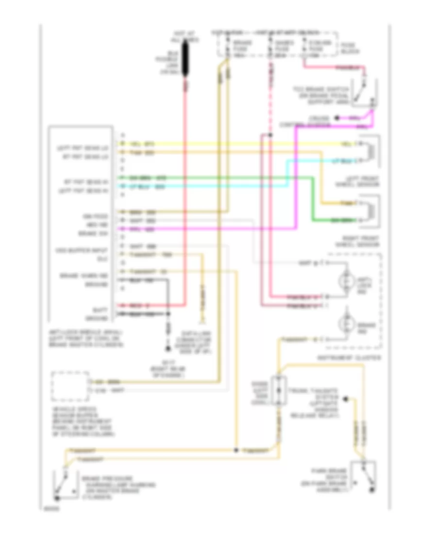
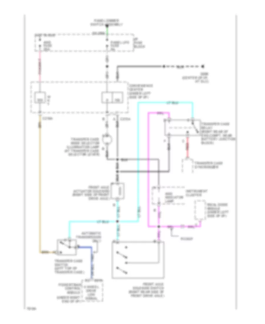
All-Wheel ABS Wiring Diagram, with DRL for GMC Pickup C1994 2500
 https://portal-diagnostov.com/license.html
Automotive Electricians Portal FZCO
Automotive Electricians Portal FZCO
https://portal-diagnostov.com/license.html
https://portal-diagnostov.com/license.html
Automotive Electricians Portal FZCO
Automotive Electricians Portal FZCO
List of elements for All-Wheel ABS Wiring Diagram, with DRL for GMC Pickup C1994 2500:
- (on master brake
- Abs ind
- Anti- lock ind
- Anti-lock module (4wal) (left front of cowl on brake master cylinder)
- Batt
- Brake fuse 15a
- Brake ind
- Brake pressure
- Brake sw
- Brake warn ind
- Bround
- C10
- Cruise control system
- Cylinder)
- Data link connector (under left side of i/p)
- Daytime running lights module (under left side of i/p)
- Diode (behind left side of i/p)
- Dlc
- Ecm-ign fuse 10a
- Fuse block
- G117 (right rear of engine)
- Gages fuse 20a
- Ground
- Hot at all times
- Hot in run
- Hot in start or run
- Ign feed
- Ignition switch
- Instrument cluster
- Left fnt sens hi
- Left fnt sens lo
- Left front wheel sensor
- Park brake switch (on park brake assembly)
- Red
- Right front wheel sensor
- Rt fnt sens hi
- Rt fnt sens lo
- Tan
- Tcc brake switch (on brake pedal support arm)
- Vehicle speed sensor buffer (behind instrument panel on right side of steering column)
- Vss buffer input
- Warning lamp warning
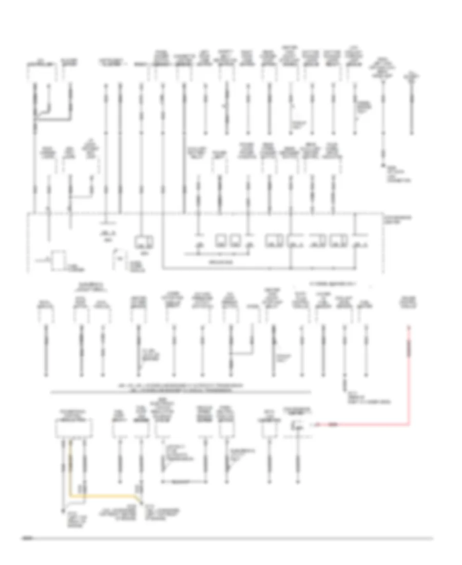
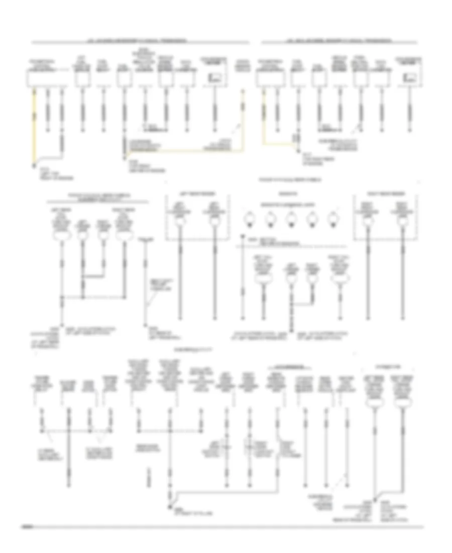
All-Wheel ABS Wiring Diagram, without DRL for GMC Pickup C1994 2500
List of elements for All-Wheel ABS Wiring Diagram, without DRL for GMC Pickup C1994 2500:
- (on master brake
- Abs ind
- Anti- lock ind
- Anti-lock module (4wal) (left front of cowl on brake master cylinder)
- Batt
- Brake fuse 15a
- Brake ind
- Brake pressure
- Brake sw
- Brake warn ind
- Bround
- C10
- Cruise control system
- Cylinder)
- Data link connector (under left side of i/p)
- Diode (left side cowl)
- Dlc
- Ecm-ign fuse 10a
- Fuse block
- G117 (right rear of engine)
- Gages fuse 20a
- Ground
- Hot at all times
- Hot in run
- Hot in start or run
- Ign feed
- Instrument cluster
- Left fnt sens hi
- Left fnt sens lo
- Left front wheel sensor
- Park brake switch (on park brake assembly)
- Red
- Right front wheel sensor
- Rt fnt sens hi
- Rt fnt sens lo
- Tan
- Tcc brake switch (on brake pedal support arm)
- Trunk, tailgate system (liftgate window release relay)
- Vehicle speed sensor buffer (behind instrument panel on right side of steering column)
- Vss buffer input
- Warning lamp warning
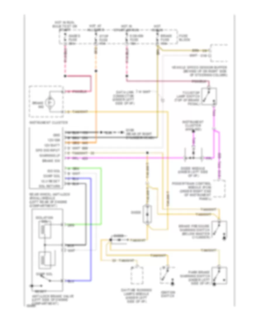
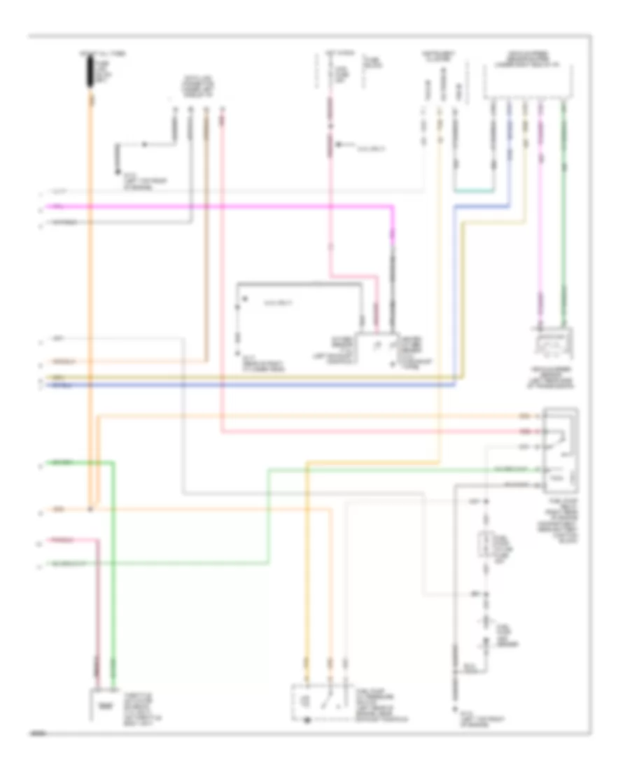
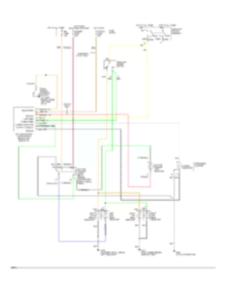
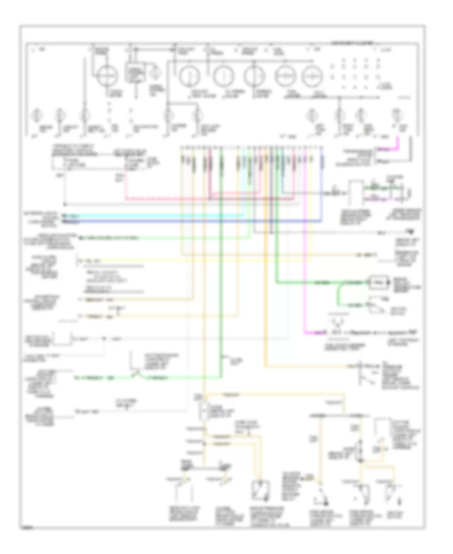
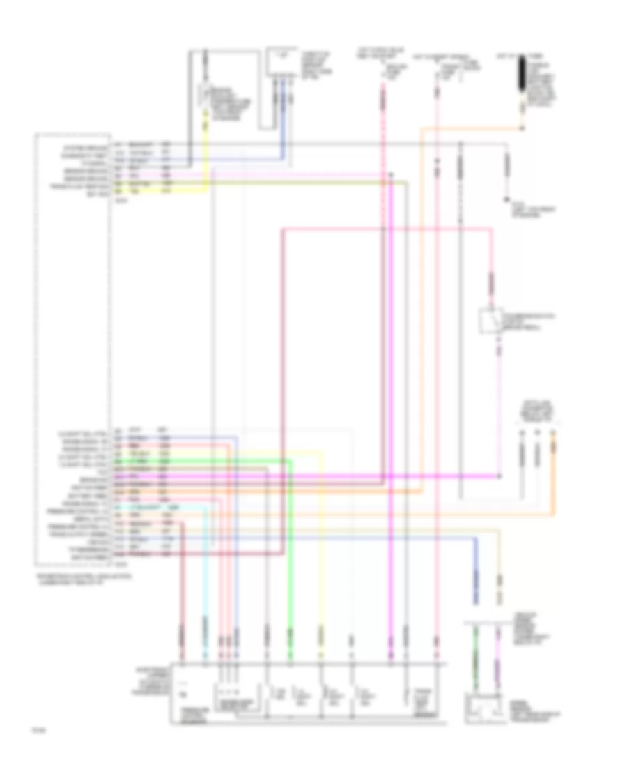
Rear ABS Wiring Diagram, with DRL for GMC Pickup C1994 2500
List of elements for Rear ABS Wiring Diagram, with DRL for GMC Pickup C1994 2500:
- 12v batt
- 12v ign
- Anti-lock brake valve (left side of engine compartment)
- Brake fuse 15a
- Brake ind
- Brake pressure warning switch (below master cylinder)
- Brake sw
- C10
- Data link connector (under left side of i/p)
- Daytime running lamps module (under left side of i/p)
- Diode
- Diode module (under left side of i/p)
- Dump sol
- E13
- Ecm-ign fuse 10a
- Fuse block
- G106 (rear of right cylinder head)
- Gages fuse 20a
- Gnd
- Hot at all times
- Hot in run
- Hot in run, bulb test or start
- Hot in start or run
- Ignition switch
- Instrument cluster
- Instrument cluster (4wd ind)
- Iso sol
- Isolation sol
- Park brake warning switch (under left side of i/p)
- Powertrain control module (pcm) (under right end of instrument panel)
- Rear wheel anti-lock (rwal) module (left rear of engine (compartment)
- Reset
- Sol return
- Spd sig input
- Stop fuse 15a
- Tcc/stop lamp switch (top of brake pedal)
- Vehicle speed sensor buffer (behind i/p on right side of steering column)
- Vlv reset
- Warning lp
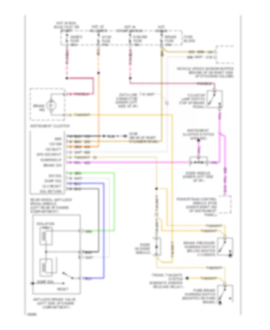
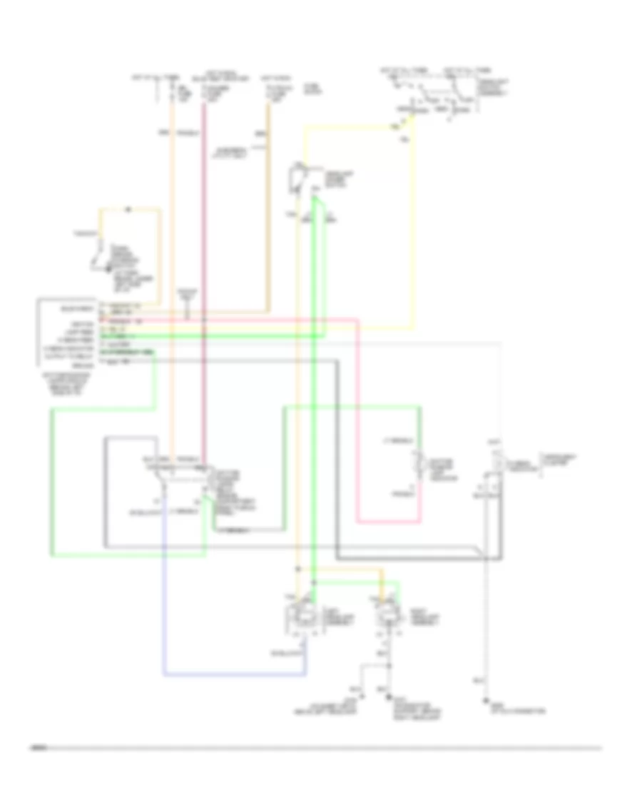
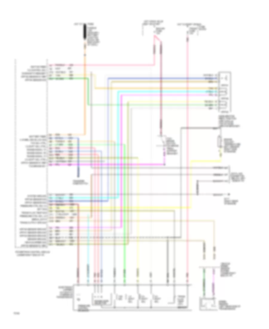
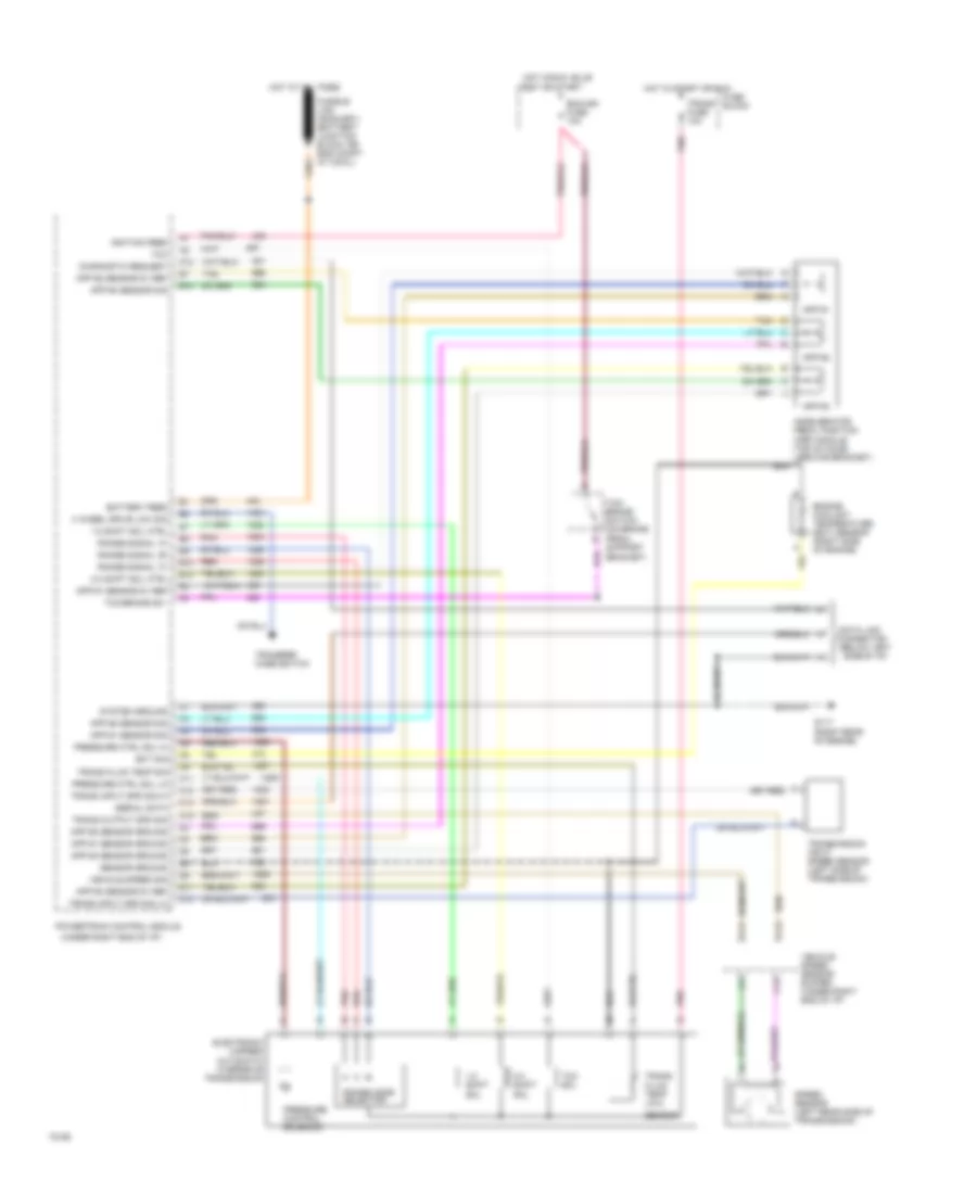
Rear ABS Wiring Diagram, without DRL for GMC Pickup C1994 2500
List of elements for Rear ABS Wiring Diagram, without DRL for GMC Pickup C1994 2500:
- (left side of engine compartment)
- 12v batt
- 12v ign
- Anti-lock brake valve
- Brake fuse 15a
- Brake ind
- Brake pressure warning switch (below master cylinder)
- Brake sw
- C10
- Data link connector (under left side of i/p)
- Diode (in diode module)
- Diode module (under left side of i/p)
- Dump sol
- E13
- Ecm-ign fuse 10a
- Fuse block
- G106 (rear of right cylinder head)
- Gages fuse 20a
- Gnd
- Hot at all times
- Hot in run
- Hot in run, bulb test or start
- Hot in start or run
- Instrument cluster
- Instrument cluster system (4wd ind)
- Iso sol
- Isolation sol
- Park brake warning switch (mounted on park brake)
- Powertrain control module (pcm) (under right ind of instrument panel)
- Rear wheel anti-lock (rwal) module (left rear of engine (compartment)
- Reset
- Sol return
- Spd sig input
- Stop fuse 15a
- Tcc/stop lamp switch (top of brake pedal)
- Trunk, tailgate system (endgate window release relay)
- Vehicle speed sensor buffer (behind i/p on right side of steering column)
- Vlv reset
- Warning lp
COMPUTER DATA LINES
4.3L
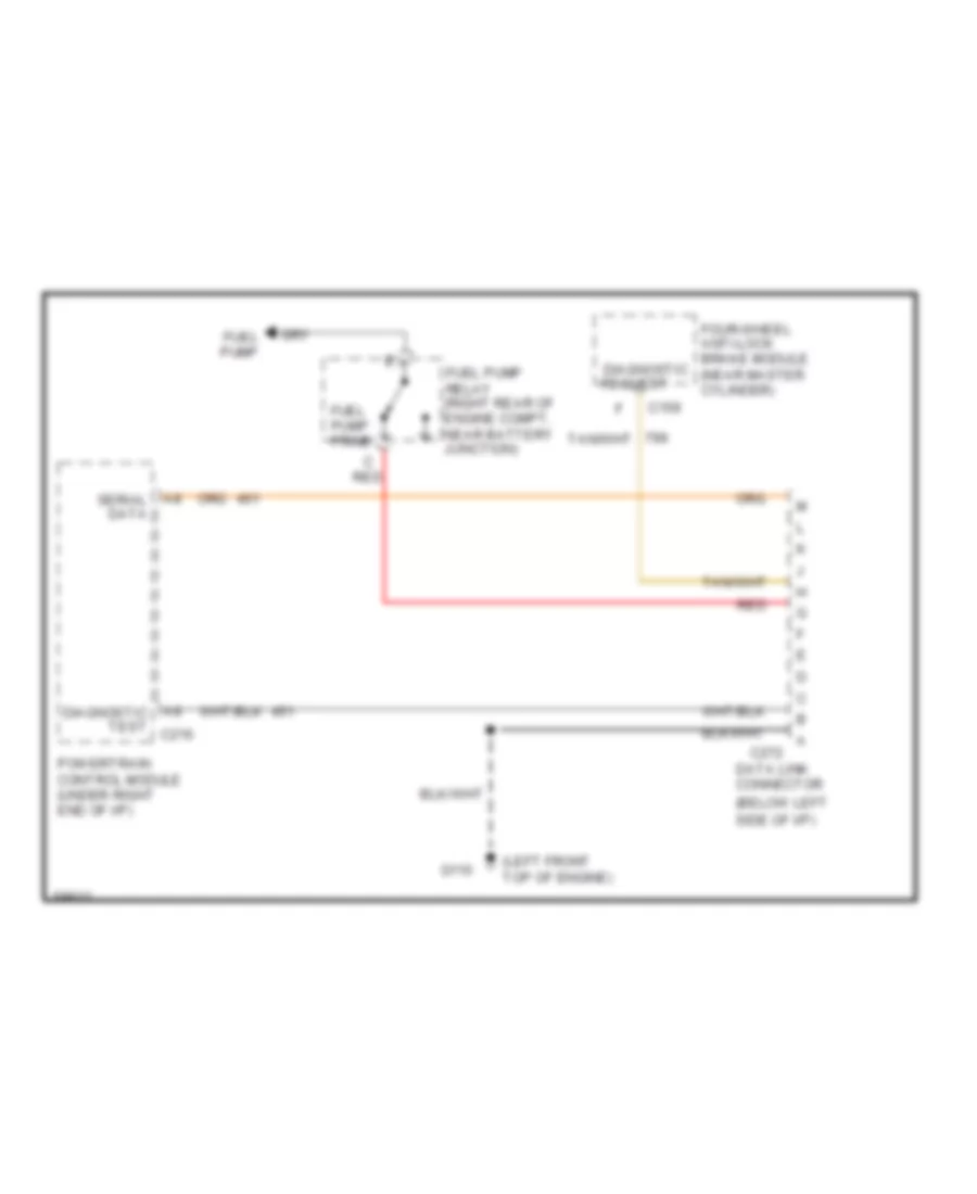
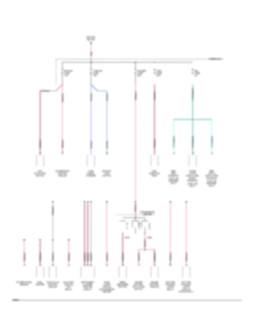
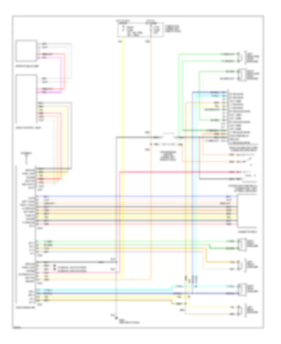
4.3L (VIN Z), Data Link Connector Wiring Diagram for GMC Pickup C1994 2500
List of elements for 4.3L (VIN Z), Data Link Connector Wiring Diagram for GMC Pickup C1994 2500:
- (below left side of i/p)
- (left front top of engine)
- A14 diagnostic test c218
- C159
- C272
- Data link connector
- F9 serial data c215
- Four-wheel anti-lock brake module diagnostic (near master cylinder)
- Fuel pump
- Fuel pump prime
- Fuel pump relay (right rear of engine compt, near battery junction)
- G110
- Powertrain control module (under right end of i/p)
- Red
- Request
5.0L
5.0L (VIN H), Data Link Connector Wiring Diagram, A/T for GMC Pickup C1994 2500
List of elements for 5.0L (VIN H), Data Link Connector Wiring Diagram, A/T for GMC Pickup C1994 2500:
- (below left side of i/p)
- (left front top of engine)
- A14 diagnostic test c218
- C159
- C272
- Data link connector
- F9 serial data c215
- Four-wheel anti-lock brake module diagnostic (near master cylinder)
- Fuel pump
- Fuel pump prime
- Fuel pump relay (right rear of engine compt, near battery junction)
- G110
- Powertrain control module (under right end of i/p)
- Red
- Request
5.0L (VIN H), Data Link Connector Wiring Diagram, M/T for GMC Pickup C1994 2500
List of elements for 5.0L (VIN H), Data Link Connector Wiring Diagram, M/T for GMC Pickup C1994 2500:
- (below left side of i/p)
- (left front top of engine)
- A8 serial data
- A9 diagnostic test c216
- C159
- C272
- Data link connector
- Four-wheel anti-lock brake module diagnostic (near master cylinder)
- Fuel pump
- Fuel pump prime
- Fuel pump relay (right rear of engine compt, near battery junction)
- G110
- Powertrain control module (under right end of i/p)
- Red
- Request
5.7L
5.7L (VIN K) HD, Data Link Connector Wiring Diagram, A/T for GMC Pickup C1994 2500
List of elements for 5.7L (VIN K) HD, Data Link Connector Wiring Diagram, A/T for GMC Pickup C1994 2500:
- (below left side of i/p)
- (left front top of engine)
- A14 diagnostic test c218
- C159
- C272
- Data link connector
- F9 serial data c215
- Four-wheel anti-lock brake module diagnostic (near master cylinder)
- Fuel pump
- Fuel pump prime
- Fuel pump relay (right rear of engine compt, near battery junction)
- G110
- Powertrain control module (under right end of i/p)
- Red
- Request
5.7L (VIN K) HD, Data Link Connector Wiring Diagram, M/T for GMC Pickup C1994 2500
List of elements for 5.7L (VIN K) HD, Data Link Connector Wiring Diagram, M/T for GMC Pickup C1994 2500:
- (below left side of i/p)
- (left front top of engine)
- A8 serial data
- A9 diagnostic test c216
- C159
- C272
- Data link connector
- Four-wheel anti-lock brake module diagnostic (near master cylinder)
- Fuel pump
- Fuel pump prime
- Fuel pump relay (right rear of engine compt, near battery junction)
- G110
- Powertrain control module (under right end of i/p)
- Red
- Request
5.7L (VIN K), Data Link Connector Wiring Diagram, A/T for GMC Pickup C1994 2500
List of elements for 5.7L (VIN K), Data Link Connector Wiring Diagram, A/T for GMC Pickup C1994 2500:
- (below left side of i/p)
- (left front top of engine)
- A14 diagnostic test c218
- C159
- C272
- Data link connector
- F9 serial data c215
- Four-wheel anti-lock brake module diagnostic (near master cylinder)
- Fuel pump
- Fuel pump prime
- Fuel pump relay (right rear of engine compt, near battery junction)
- G110
- Powertrain control module (under right end of i/p)
- Red
- Request
5.7L (VIN K), Data Link Connector Wiring Diagram, M/T for GMC Pickup C1994 2500
List of elements for 5.7L (VIN K), Data Link Connector Wiring Diagram, M/T for GMC Pickup C1994 2500:
- (below left side of i/p)
- (left front top of engine)
- A8 serial data
- A9 diagnostic test c216
- C159
- C272
- Data link connector
- Four-wheel anti-lock brake module diagnostic (near master cylinder)
- Fuel pump
- Fuel pump prime
- Fuel pump relay (right rear of engine compt, near battery junction)
- G110
- Powertrain control module (under right end of i/p)
- Red
- Request
6.5L
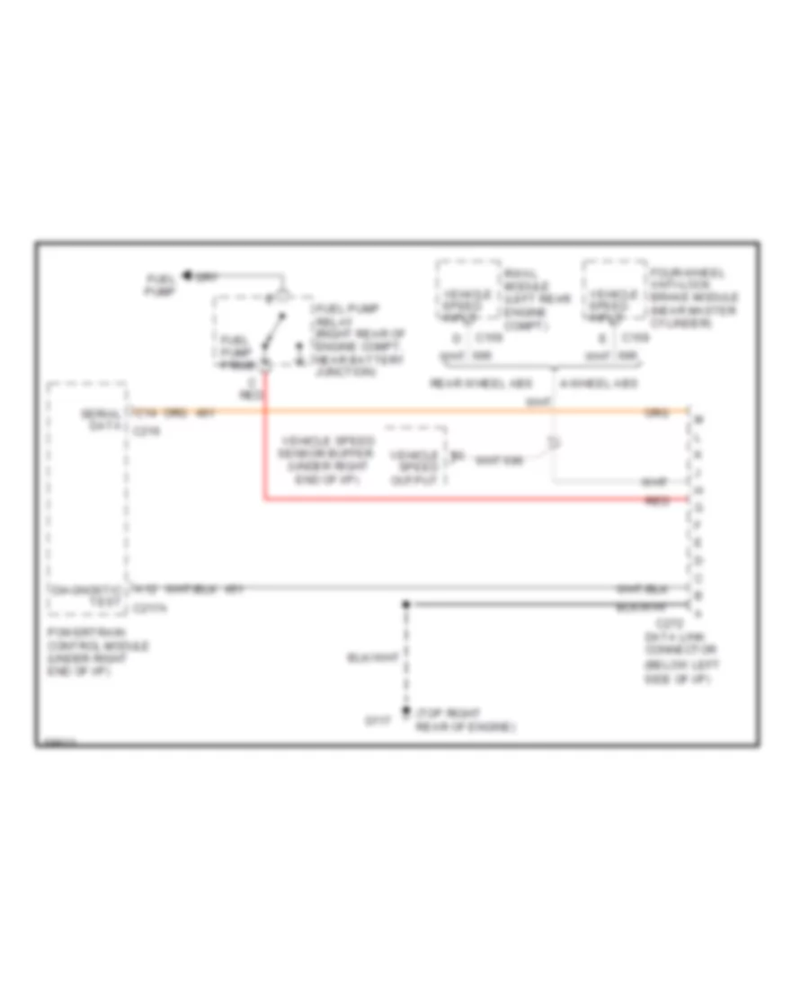
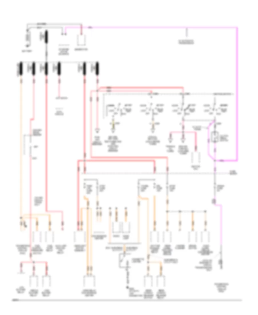
6.5L (VIN F), Data Link Connector Wiring Diagram for GMC Pickup C1994 2500
List of elements for 6.5L (VIN F), Data Link Connector Wiring Diagram for GMC Pickup C1994 2500:
- (below left side of i/p)
- (top right rear of engine)
- (under right
- 4-wheel abs
- A12 diagnostic test c217a
- C14 serial data c216
- C159
- C272
- Data link connector
- End of i/p)
- Four-wheel anti-lock brake module (near master cylinder)
- Fuel pump
- Fuel pump prime
- Fuel pump relay (right rear of engine compt, near battery junction)
- G117
- Powertrain control module (under right end of i/p)
- Rear wheel abs
- Red
- Rwal module vehicle (left rear engine compt)
- Speed input
- Speed output
- Vehicle
- Vehicle speed sensor buffer
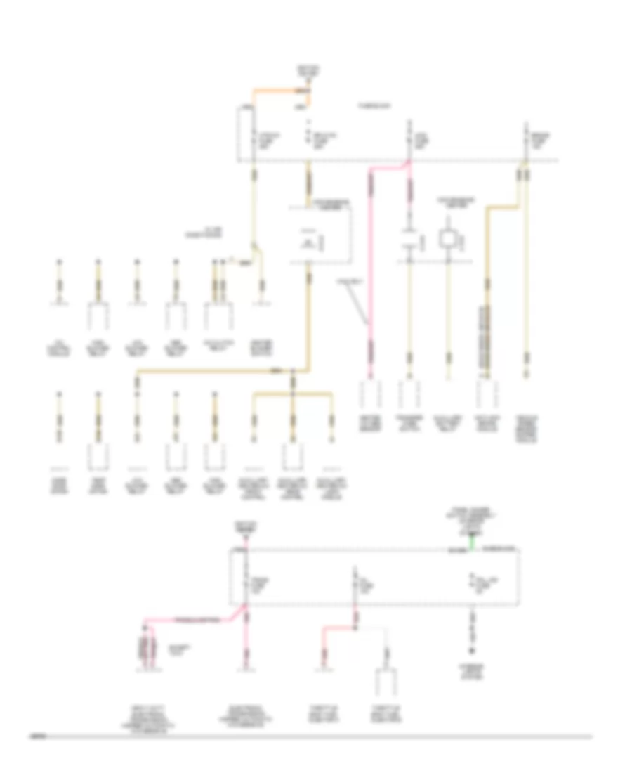
6.5L (VIN P), Data Link Connector Wiring Diagram for GMC Pickup C1994 2500
List of elements for 6.5L (VIN P), Data Link Connector Wiring Diagram for GMC Pickup C1994 2500:
- (below left side of i/p)
- (top right rear of engine)
- (under right
- 4-wheel abs
- A12 diagnostic test c217a
- C14 serial data c216
- C159
- C272
- Data link connector
- End of i/p)
- Four-wheel anti-lock brake module (near master cylinder)
- Fuel pump
- Fuel pump prime
- Fuel pump relay (right rear of engine compt, near battery junction)
- G117
- Powertrain control module (under right end of i/p)
- Rear wheel abs
- Red
- Rwal module vehicle (left rear engine compt)
- Speed input
- Speed output
- Vehicle
- Vehicle speed sensor buffer
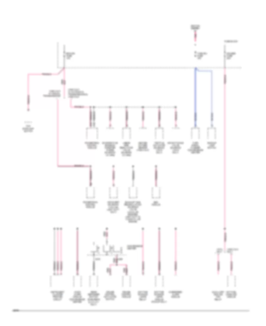
6.5L (VIN S), Data Link Connector Wiring Diagram for GMC Pickup C1994 2500
List of elements for 6.5L (VIN S), Data Link Connector Wiring Diagram for GMC Pickup C1994 2500:
- (below left side of i/p)
- (top right rear of engine)
- (under right
- 4-wheel abs
- A12 diagnostic test c217a
- C14 serial data c216
- C159
- C272
- Data link connector
- End of i/p)
- Four-wheel anti-lock brake module (near master cylinder)
- Fuel pump
- Fuel pump prime
- Fuel pump relay (right rear of engine compt, near battery junction)
- G117
- Powertrain control module (under right end of i/p)
- Rear wheel abs
- Red
- Rwal module vehicle (left rear engine compt)
- Speed input
- Speed output
- Vehicle
- Vehicle speed sensor buffer
7.4L
7.4L (VIN N), Data Link Connector Wiring Diagram for GMC Pickup C1994 2500
List of elements for 7.4L (VIN N), Data Link Connector Wiring Diagram for GMC Pickup C1994 2500:
- (below left side of i/p)
- (left front top of engine)
- A14 diagnostic test c218
- C159
- C272
- Data link connector
- F9 serial data c215
- Four-wheel anti-lock brake module diagnostic (near master cylinder)
- Fuel pump
- Fuel pump prime
- Fuel pump relay (right rear of engine compt, near battery junction)
- G110
- Powertrain control module (under right end of i/p)
- Red
- Request
CRUISE CONTROL
4.3L
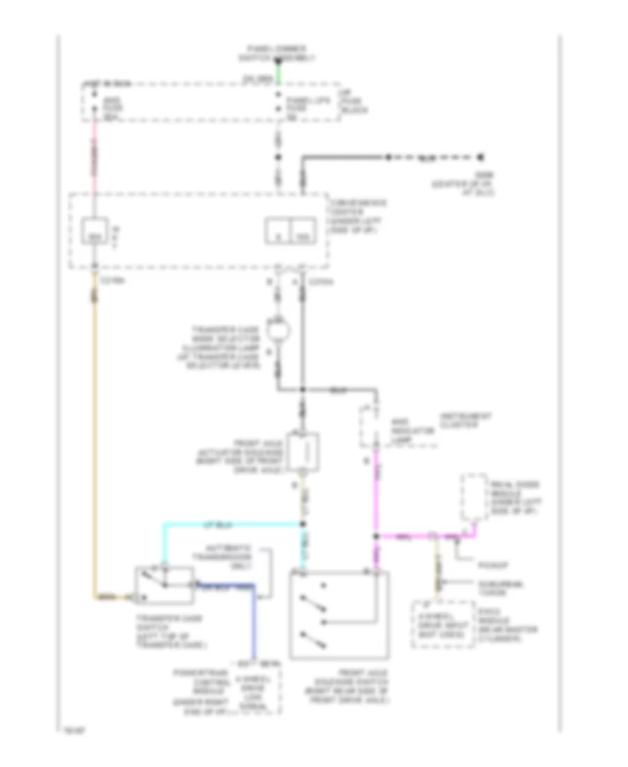
4.3L (VIN Z), Cruise Control Wiring Diagram for GMC Pickup C1994 2500
List of elements for 4.3L (VIN Z), Cruise Control Wiring Diagram for GMC Pickup C1994 2500:
- (4.3l vin z & 5.7l & 5.7l hd v8 vin k)
- (at top of
- (at top of brake
- (at top of clutch
- (behind right side of instrument panel)
- (under left side
- (under left side of
- 12vdc ign
- B10
- Brake fuse 15a
- Brake pedal)
- C12
- C227a
- C229
- C286
- C289
- C290
- Clutch switch
- Compartment)
- Convenience center
- Cruise control brake switch
- Cruise control module (left rear side of engine
- Cruise control switch
- Cruise input
- Cruise on input
- Cruise release
- Ecm-ign fuse 10a
- Fuse block
- G110 (top left front of engine)
- G125 (top front center of engine)
- Gauges fuse 20a
- Ground
- Hot at all times
- Hot in run
- Hot in run, bulb test or start
- Instrument panel)
- N/0
- N/c
- Nca
- Of instrument
- Off
- Panel)
- Pcm signal
- Pedal)
- Power distri- bution
- Powertrain control module (pcm)
- R/a
- R/a signal
- S/c
- S/c signal
- Servo posit input
- Solid state
- Speed sensor input
- Stop fuse 15a
- Stop lp sw input
- System
- Tan
- Tcc/ stoplamp switch
- Vehicle speed sensor (left rear side of transmission)
- Vehicle speed sensor buffer (behind upper right side of instrument panel)
- With manual transaxle
- Without manual transaxle
5.0L
5.0L (VIN H), Cruise Control Wiring Diagram for GMC Pickup C1994 2500
List of elements for 5.0L (VIN H), Cruise Control Wiring Diagram for GMC Pickup C1994 2500:
- (4.3l vin z & 5.7l & 5.7l hd v8 vin k)
- (at top of
- (at top of brake
- (at top of clutch
- (behind right side of instrument panel)
- (under left side
- (under left side of
- 12vdc ign
- B10
- Brake fuse 15a
- Brake pedal)
- C12
- C227a
- C229
- C286
- C289
- C290
- Clutch switch
- Compartment)
- Convenience center
- Cruise control brake switch
- Cruise control module (left rear side of engine
- Cruise control switch
- Cruise input
- Cruise on input
- Cruise release
- Ecm-ign fuse 10a
- Fuse block
- G110 (top left front of engine)
- G125 (top front center of engine)
- Gauges fuse 20a
- Ground
- Hot at all times
- Hot in run
- Hot in run, bulb test or start
- Instrument panel)
- N/0
- N/c
- Nca
- Of instrument
- Off
- Panel)
- Pcm signal
- Pedal)
- Power distri- bution
- Powertrain control module (pcm)
- R/a
- R/a signal
- S/c
- S/c signal
- Servo posit input
- Solid state
- Speed sensor input
- Stop fuse 15a
- Stop lp sw input
- System
- Tan
- Tcc/ stoplamp switch
- Vehicle speed sensor (left rear side of transmission)
- Vehicle speed sensor buffer (behind upper right side of instrument panel)
- With manual transaxle
- Without manual transaxle
5.7L
5.7L (VIN K), Cruise Control Wiring Diagram for GMC Pickup C1994 2500
List of elements for 5.7L (VIN K), Cruise Control Wiring Diagram for GMC Pickup C1994 2500:
- (4.3l vin z & 5.7l & 5.7l hd v8 vin k)
- (at top of
- (at top of brake
- (at top of clutch
- (behind right side of instrument panel)
- (under left side
- (under left side of
- 12vdc ign
- B10
- Brake fuse 15a
- Brake pedal)
- C12
- C227a
- C229
- C286
- C289
- C290
- Clutch switch
- Compartment)
- Convenience center
- Cruise control brake switch
- Cruise control module (left rear side of engine
- Cruise control switch
- Cruise input
- Cruise on input
- Cruise release
- Ecm-ign fuse 10a
- Fuse block
- G110 (top left front of engine)
- G125 (top front center of engine)
- Gauges fuse 20a
- Ground
- Hot at all times
- Hot in run
- Hot in run, bulb test or start
- Instrument panel)
- N/0
- N/c
- Nca
- Of instrument
- Off
- Panel)
- Pcm signal
- Pedal)
- Power distri- bution
- Powertrain control module (pcm)
- R/a
- R/a signal
- S/c
- S/c signal
- Servo posit input
- Solid state
- Speed sensor input
- Stop fuse 15a
- Stop lp sw input
- System
- Tan
- Tcc/ stoplamp switch
- Vehicle speed sensor (left rear side of transmission)
- Vehicle speed sensor buffer (behind upper right side of instrument panel)
- With manual transaxle
- Without manual transaxle
6.5L
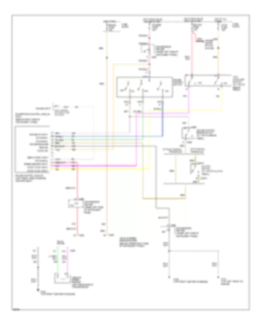
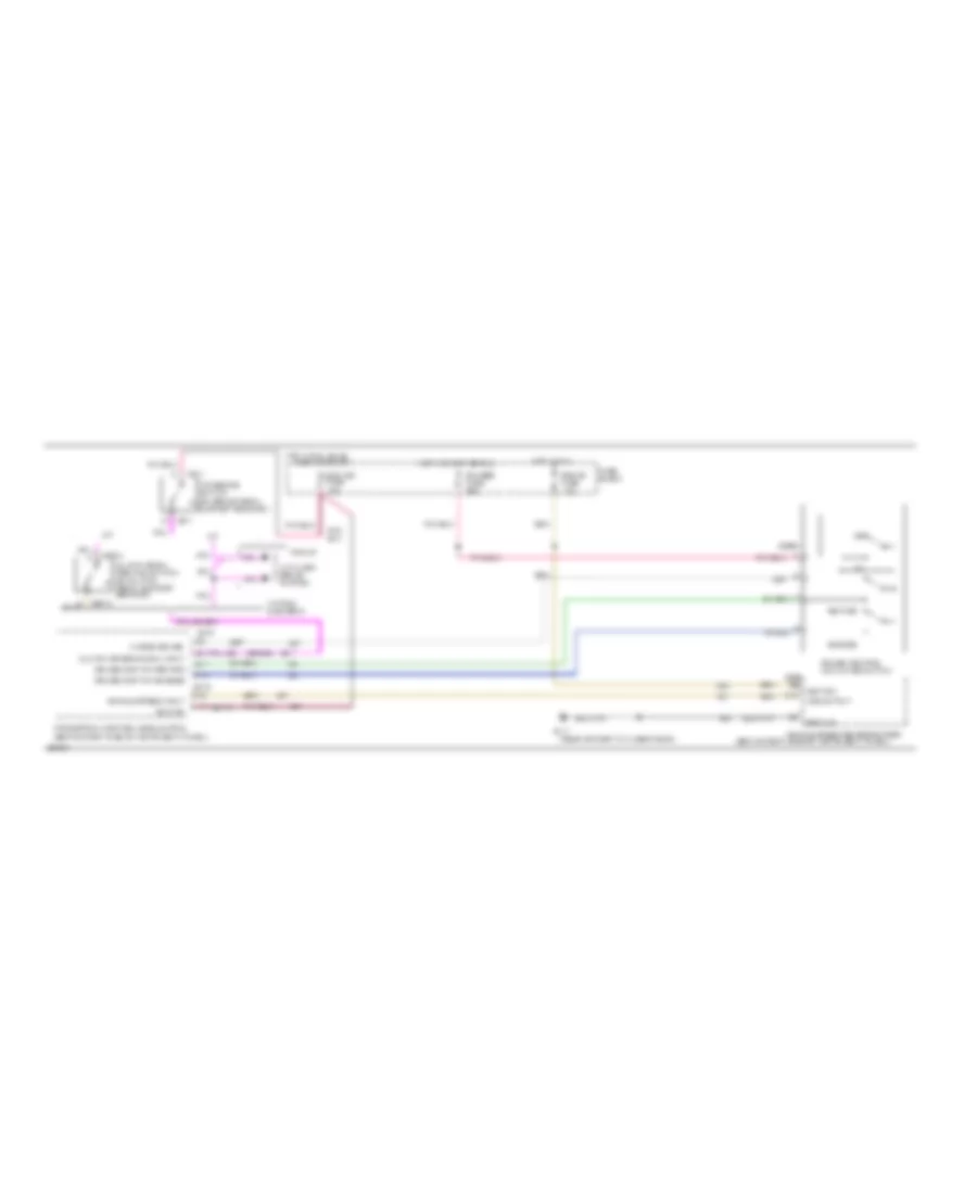
6.5L (VIN F), Cruise Control Wiring Diagram for GMC Pickup C1994 2500
List of elements for 6.5L (VIN F), Cruise Control Wiring Diagram for GMC Pickup C1994 2500:
- (behind right side of instrument panel)
- (on brake pedal support bracket)
- (rear of right cylinder head)
- 15a
- 3 mode cruise
- A/t
- Anti-lock brake system
- Brake fuse
- C13
- C215
- C216 c15
- C217a
- C226a
- C227a
- C271
- C289
- Clutch or (brake sw) input
- Clutch pedal position switch (on clutch pedal support bracket)
- Cruise cont sw-engage
- Cruise cont sw-retard
- Cruise control activator switch
- D11
- D15
- Ecm -ign fuse 10a
- Engage
- Fuse block
- G117
- Gauges fuse 20a
- Ground
- Hot in run
- Hot in run, bulb
- Hot in start or run
- Ignition
- M/t
- Off
- Pickup
- Powertrain control module (pcm) (behind right side of instrument panel)
- Retard
- Tcc/brake switch
- Test or start
- Vehicle speed input
- Vehicle speed sensor buffer
- Vss output
- Yukon& suburban
6.5L (VIN P), Cruise Control Wiring Diagram for GMC Pickup C1994 2500
List of elements for 6.5L (VIN P), Cruise Control Wiring Diagram for GMC Pickup C1994 2500:
- (behind right side of instrument panel)
- (on brake pedal support bracket)
- (rear of right cylinder head)
- 15a
- 3 mode cruise
- A/t
- Anti-lock brake system
- Brake fuse
- C13
- C215
- C216 c15
- C217a
- C226a
- C227a
- C271
- C289
- Clutch or (brake sw) input
- Clutch pedal position switch (on clutch pedal support bracket)
- Cruise cont sw-engage
- Cruise cont sw-retard
- Cruise control activator switch
- D11
- D15
- Ecm -ign fuse 10a
- Engage
- Fuse block
- G117
- Gauges fuse 20a
- Ground
- Hot in run
- Hot in run, bulb
- Hot in start or run
- Ignition
- M/t
- Off
- Pickup
- Powertrain control module (pcm) (behind right side of instrument panel)
- Retard
- Tcc/brake switch
- Test or start
- Vehicle speed input
- Vehicle speed sensor buffer
- Vss output
- Yukon& suburban
6.5L (VIN S), Cruise Control Wiring Diagram for GMC Pickup C1994 2500
List of elements for 6.5L (VIN S), Cruise Control Wiring Diagram for GMC Pickup C1994 2500:
- (behind right side of instrument panel)
- (on brake pedal support bracket)
- (rear of right cylinder head)
- 15a
- 3 mode cruise
- A/t
- Anti-lock brake system
- Brake fuse
- C13
- C215
- C216 c15
- C217a
- C226a
- C227a
- C271
- C289
- Clutch or (brake sw) input
- Clutch pedal position switch (on clutch pedal support bracket)
- Cruise cont sw-engage
- Cruise cont sw-retard
- Cruise control activator switch
- D11
- D15
- Ecm -ign fuse 10a
- Engage
- Fuse block
- G117
- Gauges fuse 20a
- Ground
- Hot in run
- Hot in run, bulb
- Hot in start or run
- Ignition
- M/t
- Off
- Pickup
- Powertrain control module (pcm) (behind right side of instrument panel)
- Retard
- Tcc/brake switch
- Test or start
- Vehicle speed input
- Vehicle speed sensor buffer
- Vss output
- Yukon& suburban
7.4L
7.4L (VIN N), Cruise Control Wiring Diagram for GMC Pickup C1994 2500
List of elements for 7.4L (VIN N), Cruise Control Wiring Diagram for GMC Pickup C1994 2500:
- (4.3l vin z & 5.7l & 5.7l hd v8 vin k)
- (at top of
- (at top of brake
- (at top of clutch
- (behind right side of instrument panel)
- (under left side
- (under left side of
- 12vdc ign
- B10
- Brake fuse 15a
- Brake pedal)
- C12
- C227a
- C229
- C286
- C289
- C290
- Clutch switch
- Compartment)
- Convenience center
- Cruise control brake switch
- Cruise control module (left rear side of engine
- Cruise control switch
- Cruise input
- Cruise on input
- Cruise release
- Ecm-ign fuse 10a
- Fuse block
- G110 (top left front of engine)
- G125 (top front center of engine)
- Gauges fuse 20a
- Ground
- Hot at all times
- Hot in run
- Hot in run, bulb test or start
- Instrument panel)
- N/0
- N/c
- Nca
- Of instrument
- Off
- Panel)
- Pcm signal
- Pedal)
- Power distri- bution
- Powertrain control module (pcm)
- R/a
- R/a signal
- S/c
- S/c signal
- Servo posit input
- Solid state
- Speed sensor input
- Stop fuse 15a
- Stop lp sw input
- System
- Tan
- Tcc/ stoplamp switch
- Vehicle speed sensor (left rear side of transmission)
- Vehicle speed sensor buffer (behind upper right side of instrument panel)
- With manual transaxle
- Without manual transaxle
DEFOGGERS
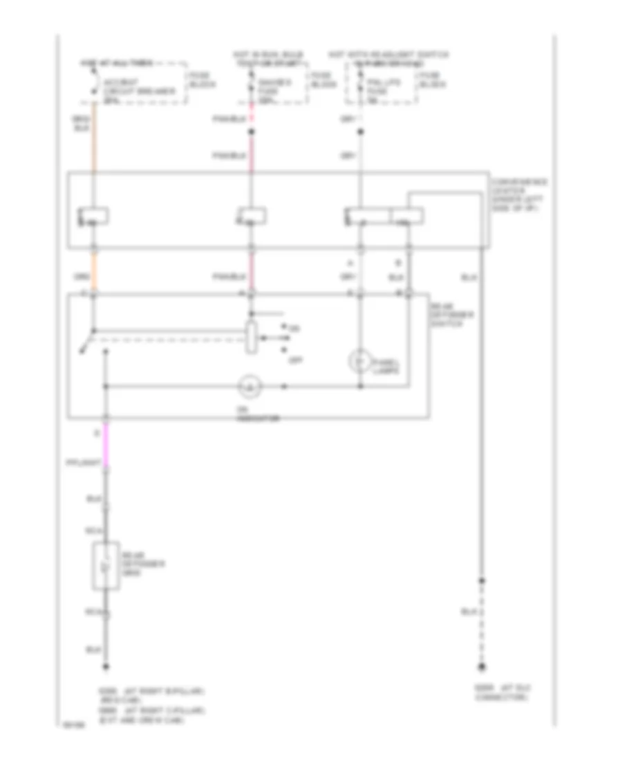
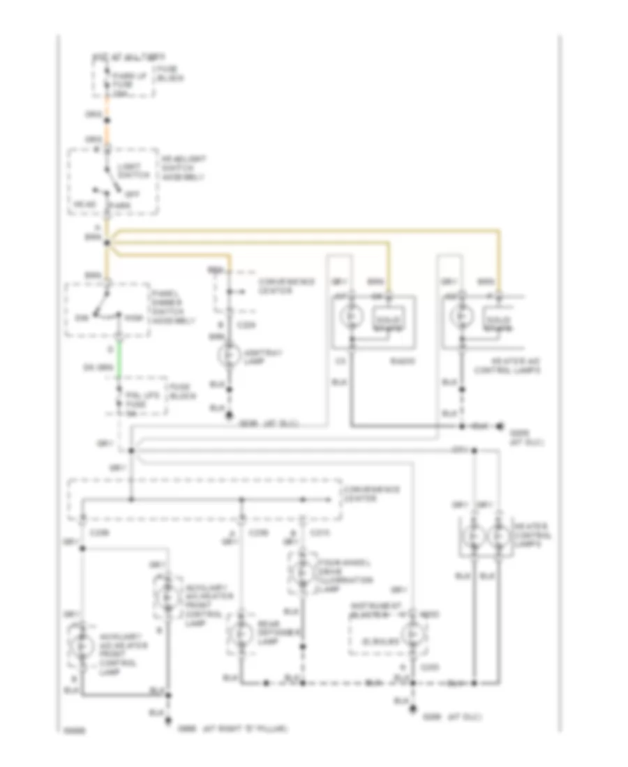
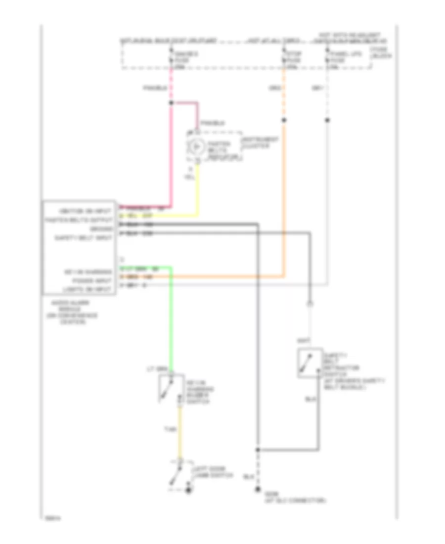
Defogger Wiring Diagram for GMC Pickup C1994 2500
List of elements for Defogger Wiring Diagram for GMC Pickup C1994 2500:
- (at dlc
- (at right b-pillar)
- (at right c-pillar)
- (ext and crew cab)
- (reg cab)
- Acc/bat circuit breaker 30a
- Connector)
- Convenience center (under left side of i/p)
- Fuse block
- G206
- G305
- G905
- Gauges fuse 20a
- Hot at all times
- Hot in run, bulb test or start
- Hot with headlight switch in park or head
- Nca
- Off
- On indicator
- Panel lamps
- Pnl lps fuse 5a
- Rear defogger grid
- Rear defogger switch
ENGINE PERFORMANCE
4.3L
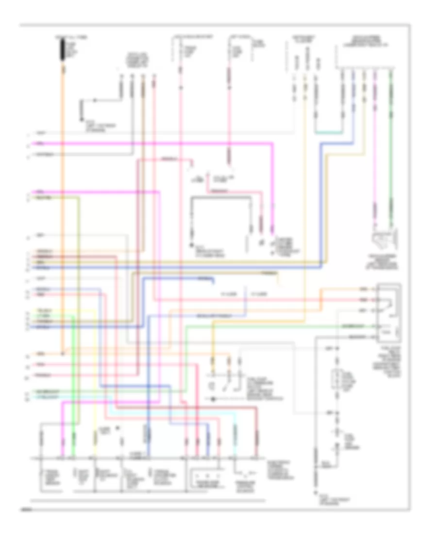
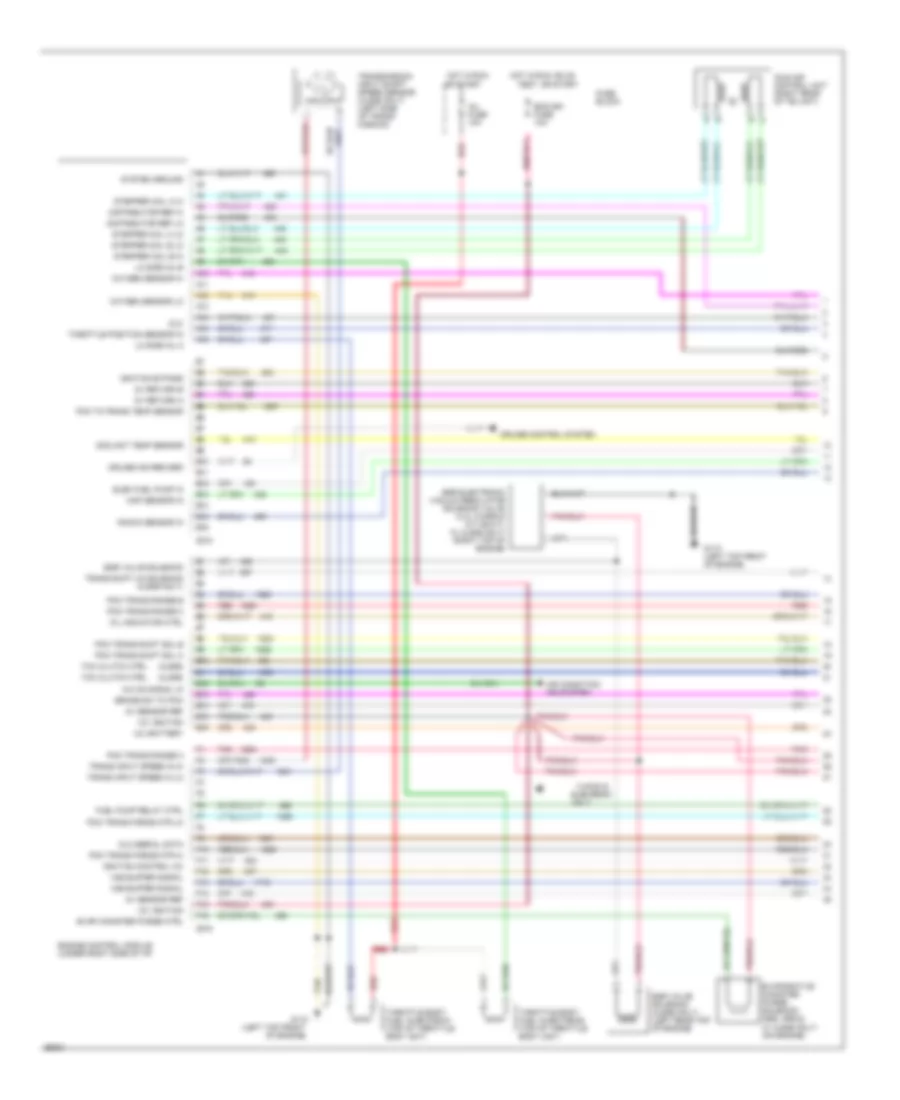
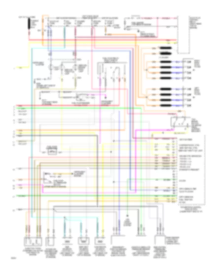
4.3L (VIN Z), Engine Performance Wiring Diagrams, A/T (1 of 3) for GMC Pickup C1994 2500
List of elements for 4.3L (VIN Z), Engine Performance Wiring Diagrams, A/T (1 of 3) for GMC Pickup C1994 2500:
- (4l60e)
- (4l80e)
- (left top front
- 12v battery
- 12v ignition
- 5v return a
- 5v return b
- 5v sensor ref
- A/c on signal in
- A10
- A11
- A12
- A13
- A14
- A15
- A16
- Air condition- ing system
- B10
- B11
- B12
- B13
- B14
- B15
- B16
- Brake sw to pcm
- C215
- C218
- Coolant temp sensor
- Cruise control system
- Cruise ind reg grd
- Distributor ref hi
- Distributor ref lo
- Dlc
- Dlc serial data
- E10
- E11
- E12
- E13
- E14
- E15
- E16
- Ecm-ign fuse 10a
- Egr electronic vacuum regulator solenoid valve (4.3l w/nrq & a/t or 5.7l w/ 4l80e only) (right top of engine)
- Egr valve solenoid
- Egr valve solenoid (4l60e only) (left rear top of engine)
- Elec fuel pump in
- Engine control module (under right side of i/p)
- Evap canister purge ctrl
- Evaporative canister purge solenoid (nb2, nrq & w/ 4l60e only) (on engine)
- F10
- F11
- F12
- F13
- F14
- F15
- F16
- Fuel pump relay ctrl
- Fuse block
- G110
- G110 (left top front of engine)
- Hot in run
- Hot in run, bulb
- Idle air control unit (right rear of tbi unit)
- Ignition bypass
- Ignition control (ic)
- Inj fuse 10a
- Knock sensor in
- Lo side inj a
- Lo side inj b
- Map sensor in
- Mil indicator ctrl
- Of engine)
- Only
- Or start
- Oxygen sensor hi
- Oxygen sensor lo
- Pcm to trans temp sensor
- Pcm trans force mtr hi
- Pcm trans force mtr lo
- Pcm trans range a
- Pcm trans range b
- Pcm trans range c
- Pcm trans shift sol a
- Pcm trans shift sol b
- Pnk
- Red
- Stepper coil a hi
- Stepper coil a lo
- Stepper coil b hi
- Stepper coil b lo
- System ground
- Tan
- Tcc clutch ctrl
- Test, or start
- Throttle body fuel injector #1 (top of throttle body unit)
- Throttle body fuel injector #2 (top of throttle body unit)
- Throttle position sensor in
- Trans input speed in hi
- Trans input speed in lo
- Trans shift 3/2 solenoid (4l60e only)
- Transmission input shaft speed sensor (4l80e only) (left side of trans- mission)
- Vss buffer signal
- Yukon & suburban
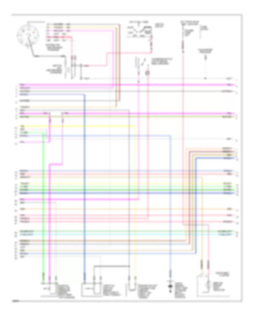
4.3L (VIN Z), Engine Performance Wiring Diagrams, A/T (2 of 3) for GMC Pickup C1994 2500
List of elements for 4.3L (VIN Z), Engine Performance Wiring Diagrams, A/T (2 of 3) for GMC Pickup C1994 2500:
- (4.3l only)
- (center rear
- Accy
- Bulb test
- Distributor
- Engine coolant temperature sensor (right top front of engine)
- Fuse block
- Gauges fuse 20a
- Hot at all times
- Hot in run, bulb test, or start
- Ignition coil (center rear of engine)
- Ignition switch
- Instrument cluster
- Knock sensor (4.3l only) (rear of engine)
- Knock sensor (right side of engine, below exhaust manifold)
- Lock
- Manifold absolute pressure sensor (right rear top of engine)
- Nca
- Of engine)
- Off
- Pnk
- Red
- Run
- Service engine soon indicator
- Start
- Tachometer test lead
- Tcc/brake switch (top of brake pedal bracket)
- Throttle position sensor (right side of throttle body)
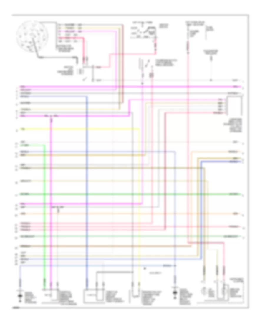
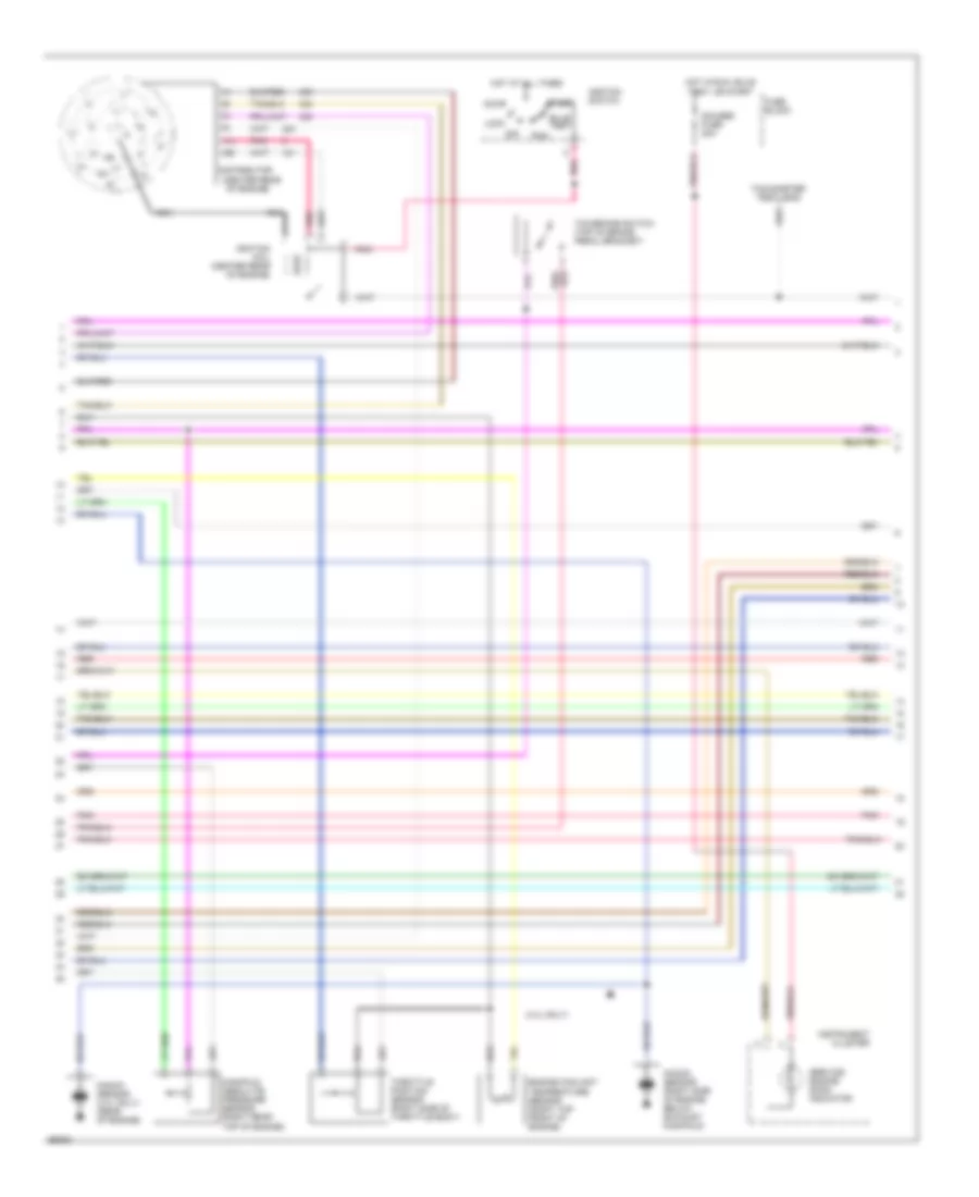
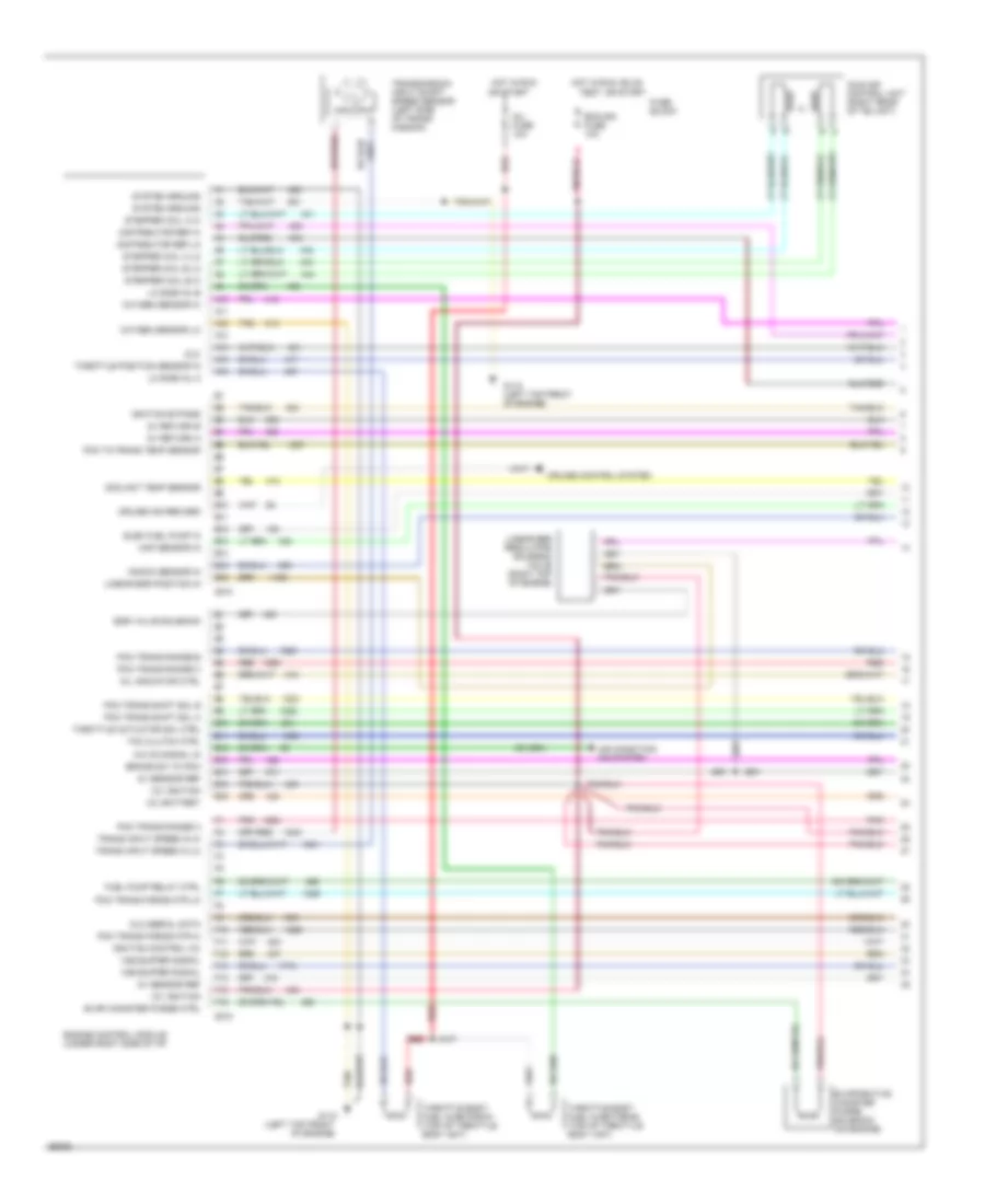
4.3L (VIN Z), Engine Performance Wiring Diagrams, A/T (3 of 3) for GMC Pickup C1994 2500
List of elements for 4.3L (VIN Z), Engine Performance Wiring Diagrams, A/T (3 of 3) for GMC Pickup C1994 2500:
- (4l60e
- (4l60e) t
- (4l80e) s
- 3-2 shift solenoid (4l60e only)
- 4.3l all or w/ nrq
- 4wd fuse 25a
- All
- C12
- C13
- C14
- C15
- Cluster
- Data link connector (under left side of i/p)
- Electronic 4-speed automatic overdrive transmission
- Fuel pump and sender
- Fuel pump in-line fuse 20a
- Fuel pump oil pressure switch (left rear of engine, near exhaust manifold)
- Fuel pump relay (right rear of engine compartment, near battery junction block)
- Fuse block
- G110 (left top front of engine)
- G117 (rear of right cylinder head)
- Heated oxygen sensor (in exhaust y-pipe)
- Hot at all times
- Hot in run
- Hot in run or start
- Instrument
- Oil press in
- Only)
- Other
- Pnk
- Pressure control solenoid
- Range mode selector
- Red
- Shift sole- noid 1-2
- Shift solenoid 2-3
- Tach in
- Tan
- Torque converter clutch solenoid
- Trans fuse 10a
- Trans- mission temp sensor
- Vehicle speed sensor (left rear side of transmission)
- Vehicle speed sensor buffer (under right end of i/p)
- Vss in
- W/ 4l60e
- W/ 4l80e
4.3L (VIN Z), Engine Performance Wiring Diagrams, M/T (1 of 3) for GMC Pickup C1994 2500
List of elements for 4.3L (VIN Z), Engine Performance Wiring Diagrams, M/T (1 of 3) for GMC Pickup C1994 2500:
- (4.3l only)
- (7.4l only)
- (left top front
- 12v battery
- 12v ignition
- 5v return a
- 5v return b
- 5v sensor ref
- A/c on signal in
- A10
- A11
- A12
- A13
- A14
- A15
- A16
- Air conditioning system
- B10
- B11
- B12
- B13
- B14
- B15
- B16
- Brake sw to pcm
- C215
- C218
- Coolant temp sensor
- Cruise control system
- Cruise ind reg grd
- Distributor ref hi
- Distributor ref lo
- Dlc
- Dlc serial data
- E10
- E11
- E12
- E13
- E14
- E15
- E16
- Ecm-ign fuse 10a
- Egr valve solenoid
- Egr valve solenoid (4.3l only) (left rear top of engine)
- Elec fuel pump in
- Engine control module (under right side of i/p)
- Evap canister purge ctrl
- Evaporative canister purge solenoid (on engine)
- F10
- F11
- F12
- F13
- F14
- F15
- F16
- Fuel pump relay ctrl
- Fuse block
- G110
- Hot in run
- Hot in run, bulb
- Idle air control unit (right rear of tbi unit)
- Ignition bypass
- Ignition control (ic)
- Inj fuse 10a
- Knock sensor in
- Linear egr position in
- Lo side inj a
- Lo side inj b
- Map sensor in
- Mil indicator ctrl
- Of engine)
- Or start
- Oxygen sensor hi
- Oxygen sensor lo
- Red
- Stepper coil a hi
- Stepper coil a lo
- Stepper coil b hi
- Stepper coil b lo
- System ground
- Tan
- Test, or start
- Throttle actuator ctrl
- Throttle body fuel injector #1 (top of throttle body unit)
- Throttle body fuel injector #2 (top of throttle body unit)
- Throttle position sensor in
- Upshift ind ctrl
- Vss buffer signal
4.3L (VIN Z), Engine Performance Wiring Diagrams, M/T (2 of 3) for GMC Pickup C1994 2500
List of elements for 4.3L (VIN Z), Engine Performance Wiring Diagrams, M/T (2 of 3) for GMC Pickup C1994 2500:
- (4.3l only)
- (center rear
- Accy
- Bulb test
- Distributor
- Engine coolant temperature sensor (right top front of engine)
- Fuse block
- Gauges fuse 20a
- Hot at all times
- Hot in run, bulb test, or start
- Ignition coil (center rear of engine)
- Ignition switch
- Instrument cluster
- Knock sensor (4.3l only) (rear of engine)
- Knock sensor (right side of engine, below exhaust manifold)
- Linear egr regulator solenoid valve (7.4l only) (right top of engine)
- Lock
- Manifold absolute pressure sensor (right rear top of engine)
- Nca
- Of engine)
- Off
- Pnk
- Run
- Service engine soon indicator
- Start
- Tachometer test lead
- Tcc/brake switch (top of brake pedal bracket)
- Throttle position sensor (right side of throttle body)
- Up- shift indic- ator
4.3L (VIN Z), Engine Performance Wiring Diagrams, M/T (3 of 3) for GMC Pickup C1994 2500
List of elements for 4.3L (VIN Z), Engine Performance Wiring Diagrams, M/T (3 of 3) for GMC Pickup C1994 2500:
- (4.3l only)
- (4.3l)
- (7.4l)
- 4wd fuse 25a
- C12
- C13
- C14
- C15
- Cluster
- Data link connector (under left side of i/p)
- Fuel pump and sender
- Fuel pump in-line fuse 20a
- Fuel pump oil pressure switch (left rear of engine, near exhaust manifold)
- Fuel pump relay (right rear of engine compartment, near battery junction block)
- Fuse block
- G110 (left top front of engine)
- G117 (rear of right cylinder head)
- Heated oxygen sensor (4.3l) (in exhaust y-pipe)
- Hot at all times
- Hot in run
- Instrument
- Oil press in
- Oxygen sensor (7.4l) (left exhaust manifold)
- Red
- Tach in
- Tan
- Throttle actuator solenoid (7.4l only) (on throttle body unit)
- Vehicle speed sensor (left rear side of transmission)
- Vehicle speed sensor buffer (under right end of i/p)
- Vss in
5.0L
5.0L (VIN H), Engine Performance Wiring Diagrams, A/T (1 of 3) for GMC Pickup C1994 2500
List of elements for 5.0L (VIN H), Engine Performance Wiring Diagrams, A/T (1 of 3) for GMC Pickup C1994 2500:
- (4l60e)
- (4l80e)
- (left top front
- 12v battery
- 12v ignition
- 5v return a
- 5v return b
- 5v sensor ref
- A/c on signal in
- A10
- A11
- A12
- A13
- A14
- A15
- A16
- Air condition- ing system
- B10
- B11
- B12
- B13
- B14
- B15
- B16
- Brake sw to pcm
- C215
- C218
- Coolant temp sensor
- Cruise control system
- Cruise ind reg grd
- Distributor ref hi
- Distributor ref lo
- Dlc
- Dlc serial data
- E10
- E11
- E12
- E13
- E14
- E15
- E16
- Ecm-ign fuse 10a
- Egr electronic vacuum regulator solenoid valve (4.3l w/nrq & a/t or 5.7l w/ 4l80e only) (right top of engine)
- Egr valve solenoid
- Egr valve solenoid (4l60e only) (left rear top of engine)
- Elec fuel pump in
- Engine control module (under right side of i/p)
- Evap canister purge ctrl
- Evaporative canister purge solenoid (nb2, nrq & w/ 4l60e only) (on engine)
- F10
- F11
- F12
- F13
- F14
- F15
- F16
- Fuel pump relay ctrl
- Fuse block
- G110
- G110 (left top front of engine)
- Hot in run
- Hot in run, bulb
- Idle air control unit (right rear of tbi unit)
- Ignition bypass
- Ignition control (ic)
- Inj fuse 10a
- Knock sensor in
- Lo side inj a
- Lo side inj b
- Map sensor in
- Mil indicator ctrl
- Of engine)
- Only
- Or start
- Oxygen sensor hi
- Oxygen sensor lo
- Pcm to trans temp sensor
- Pcm trans force mtr hi
- Pcm trans force mtr lo
- Pcm trans range a
- Pcm trans range b
- Pcm trans range c
- Pcm trans shift sol a
- Pcm trans shift sol b
- Pnk
- Red
- Stepper coil a hi
- Stepper coil a lo
- Stepper coil b hi
- Stepper coil b lo
- System ground
- Tan
- Tcc clutch ctrl
- Test, or start
- Throttle body fuel injector #1 (top of throttle body unit)
- Throttle body fuel injector #2 (top of throttle body unit)
- Throttle position sensor in
- Trans input speed in hi
- Trans input speed in lo
- Trans shift 3/2 solenoid (4l60e only)
- Transmission input shaft speed sensor (4l80e only) (left side of trans- mission)
- Vss buffer signal
- Yukon & suburban
5.0L (VIN H), Engine Performance Wiring Diagrams, A/T (2 of 3) for GMC Pickup C1994 2500
List of elements for 5.0L (VIN H), Engine Performance Wiring Diagrams, A/T (2 of 3) for GMC Pickup C1994 2500:
- (4.3l only)
- (center rear
- Accy
- Bulb test
- Distributor
- Engine coolant temperature sensor (right top front of engine)
- Fuse block
- Gauges fuse 20a
- Hot at all times
- Hot in run, bulb test, or start
- Ignition coil (center rear of engine)
- Ignition switch
- Instrument cluster
- Knock sensor (4.3l only) (rear of engine)
- Knock sensor (right side of engine, below exhaust manifold)
- Lock
- Manifold absolute pressure sensor (right rear top of engine)
- Nca
- Of engine)
- Off
- Pnk
- Red
- Run
- Service engine soon indicator
- Start
- Tachometer test lead
- Tcc/brake switch (top of brake pedal bracket)
- Throttle position sensor (right side of throttle body)
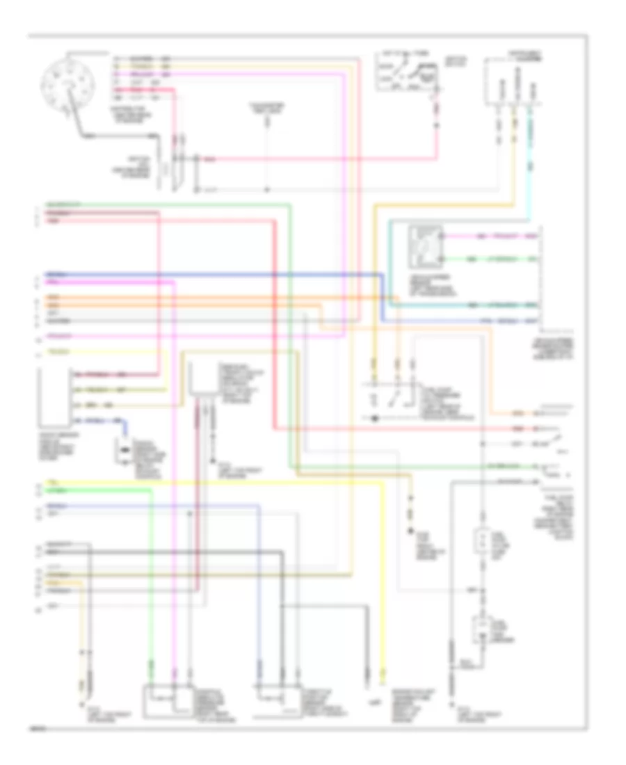
5.0L (VIN H), Engine Performance Wiring Diagrams, A/T (3 of 3) for GMC Pickup C1994 2500
List of elements for 5.0L (VIN H), Engine Performance Wiring Diagrams, A/T (3 of 3) for GMC Pickup C1994 2500:
- (4l60e
- (4l60e) t
- (4l80e) s
- 3-2 shift solenoid (4l60e only)
- 4.3l all or w/ nrq
- 4wd fuse 25a
- All
- C12
- C13
- C14
- C15
- Cluster
- Data link connector (under left side of i/p)
- Electronic 4-speed automatic overdrive transmission
- Fuel pump and sender
- Fuel pump in-line fuse 20a
- Fuel pump oil pressure switch (left rear of engine, near exhaust manifold)
- Fuel pump relay (right rear of engine compartment, near battery junction block)
- Fuse block
- G110 (left top front of engine)
- G117 (rear of right cylinder head)
- Heated oxygen sensor (in exhaust y-pipe)
- Hot at all times
- Hot in run
- Hot in run or start
- Instrument
- Oil press in
- Only)
- Other
- Pnk
- Pressure control solenoid
- Range mode selector
- Red
- Shift sole- noid 1-2
- Shift solenoid 2-3
- Tach in
- Tan
- Torque converter clutch solenoid
- Trans fuse 10a
- Trans- mission temp sensor
- Vehicle speed sensor (left rear side of transmission)
- Vehicle speed sensor buffer (under right end of i/p)
- Vss in
- W/ 4l60e
- W/ 4l80e
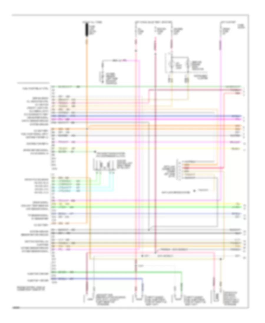
5.0L (VIN H), Engine Performance Wiring Diagrams, M/T (1 of 2) for GMC Pickup C1994 2500
List of elements for 5.0L (VIN H), Engine Performance Wiring Diagrams, M/T (1 of 2) for GMC Pickup C1994 2500:
- (5.7l hd only)
- (a/c compressor clutch)
- 12v battery
- 12v ignition
- 5v sensor ref
- A/c on signal in
- A10
- A11
- A12
- Air conditioning system
- Air switch solenoid
- Air switch solenoid (5.0l & 5.7l- pickup only) (right front of engine)
- Anti-lock brake system
- B10
- B11
- B12
- C10
- C11
- C12
- C13
- C14
- C15
- C16
- C216
- Coolant temp sens sig
- Crank fuse 5a
- Crank signal
- D10
- D11
- D12
- D13
- D14
- D15
- D16
- Data link connector (under left side of i/p)
- Distributor ref hi
- Distributor ref lo
- Dlc diagnostic test
- Dlc serial data
- Ecm-ign fuse 10a
- Egr solenoid
- Engine control module (under right side of i/p)
- Exhaust gas recirculation solenoid (5.0l & 5.7l ld only) (left rear top of engine)
- Fuel pump relay ctrl
- Fuel pump signal input
- Fuse block
- Gauges fuse 20a
- Hot at all times
- Hot in run, bulb test, or start
- Hot in start
- Iac coil a hi
- Iac coil a lo
- Iac coil b hi
- Iac coil b lo
- Ic bypass
- Idle air control unit (right rear of tbi unit)
- Ignition control (ic)
- Inj fuse 10a
- Injector 1 driver
- Injector 2 driver
- Instrument cluster
- Map 5v sensor ground
- Map sensor signal
- Mil indicator ctrl
- Oxygen sensor (left side exhaust manifold)
- Oxygen sensor ground
- Oxygen sensor signal
- Red
- Sensor return ground
- Service engine soon indicator
- Spark retard signal
- System ground
- Tan
- Throttle body fuel injector #1 (top of throttle body unit)
- Throttle body fuel injector #2 (top of throttle body unit)
- Tp sensor signal
- Up- shift lamp
- Upshift lamp ctrl
- Vss buffer signal
5.0L (VIN H), Engine Performance Wiring Diagrams, M/T (2 of 2) for GMC Pickup C1994 2500
List of elements for 5.0L (VIN H), Engine Performance Wiring Diagrams, M/T (2 of 2) for GMC Pickup C1994 2500:
- (center rear
- Accy
- Bulb test
- C12
- C14
- C15
- Distributor
- Egr elec- tronic vacuum regulator solenoid (5.7l hd only) (right top of engine)
- Engine coolant temperature sensor (right top front of engine)
- Fuel pump and sender
- Fuel pump in-line fuse 20a
- Fuel pump oil pressure switch (left rear of engine, near exhaust manifold)
- Fuel pump relay (right rear of engine compartment, near battery junction block)
- G110 (left top front of engine)
- G125 (top front center of engine)
- Hot at all times
- Ignition coil (center rear of engine)
- Ignition switch
- Instrument cluster
- Knock sensor (right side of engine, below exhaust manifold)
- Knock sensor module (above right side rocker cover)
- Lock
- Manifold absolute pressure sensor (right rear top of engine)
- Nca
- Of engine)
- Off
- Oil press in
- Pnk
- Red
- Run
- Start
- Tach in
- Tachometer test lead
- Tan
- Throttle position sensor (right side of throttle body)
- Vehicle speed sensor (left rear side of transmission)
- Vehicle speed sensor buffer (under right side end of i/p)
- Vss in
5.7L
5.7L (VIN K), Engine Performance Wiring Diagrams, A/T (1 of 3) for GMC Pickup C1994 2500
List of elements for 5.7L (VIN K), Engine Performance Wiring Diagrams, A/T (1 of 3) for GMC Pickup C1994 2500:
- (4l60e)
- (4l80e)
- (left top front
- 12v battery
- 12v ignition
- 5v return a
- 5v return b
- 5v sensor ref
- A/c on signal in
- A10
- A11
- A12
- A13
- A14
- A15
- A16
- Air condition- ing system
- B10
- B11
- B12
- B13
- B14
- B15
- B16
- Brake sw to pcm
- C215
- C218
- Coolant temp sensor
- Cruise control system
- Cruise ind reg grd
- Distributor ref hi
- Distributor ref lo
- Dlc
- Dlc serial data
- E10
- E11
- E12
- E13
- E14
- E15
- E16
- Ecm-ign fuse 10a
- Egr electronic vacuum regulator solenoid valve (4.3l w/nrq & a/t or 5.7l w/ 4l80e only) (right top of engine)
- Egr valve solenoid
- Egr valve solenoid (4l60e only) (left rear top of engine)
- Elec fuel pump in
- Engine control module (under right side of i/p)
- Evap canister purge ctrl
- Evaporative canister purge solenoid (nb2, nrq & w/ 4l60e only) (on engine)
- F10
- F11
- F12
- F13
- F14
- F15
- F16
- Fuel pump relay ctrl
- Fuse block
- G110
- G110 (left top front of engine)
- Hot in run
- Hot in run, bulb
- Idle air control unit (right rear of tbi unit)
- Ignition bypass
- Ignition control (ic)
- Inj fuse 10a
- Knock sensor in
- Lo side inj a
- Lo side inj b
- Map sensor in
- Mil indicator ctrl
- Of engine)
- Only
- Or start
- Oxygen sensor hi
- Oxygen sensor lo
- Pcm to trans temp sensor
- Pcm trans force mtr hi
- Pcm trans force mtr lo
- Pcm trans range a
- Pcm trans range b
- Pcm trans range c
- Pcm trans shift sol a
- Pcm trans shift sol b
- Pnk
- Red
- Stepper coil a hi
- Stepper coil a lo
- Stepper coil b hi
- Stepper coil b lo
- System ground
- Tan
- Tcc clutch ctrl
- Test, or start
- Throttle body fuel injector #1 (top of throttle body unit)
- Throttle body fuel injector #2 (top of throttle body unit)
- Throttle position sensor in
- Trans input speed in hi
- Trans input speed in lo
- Trans shift 3/2 solenoid (4l60e only)
- Transmission input shaft speed sensor (4l80e only) (left side of trans- mission)
- Vss buffer signal
- Yukon & suburban
5.7L (VIN K), Engine Performance Wiring Diagrams, A/T (2 of 3) for GMC Pickup C1994 2500
List of elements for 5.7L (VIN K), Engine Performance Wiring Diagrams, A/T (2 of 3) for GMC Pickup C1994 2500:
- (4.3l only)
- (center rear
- Accy
- Bulb test
- Distributor
- Engine coolant temperature sensor (right top front of engine)
- Fuse block
- Gauges fuse 20a
- Hot at all times
- Hot in run, bulb test, or start
- Ignition coil (center rear of engine)
- Ignition switch
- Instrument cluster
- Knock sensor (4.3l only) (rear of engine)
- Knock sensor (right side of engine, below exhaust manifold)
- Lock
- Manifold absolute pressure sensor (right rear top of engine)
- Nca
- Of engine)
- Off
- Pnk
- Red
- Run
- Service engine soon indicator
- Start
- Tachometer test lead
- Tcc/brake switch (top of brake pedal bracket)
- Throttle position sensor (right side of throttle body)
5.7L (VIN K), Engine Performance Wiring Diagrams, A/T (3 of 3) for GMC Pickup C1994 2500
List of elements for 5.7L (VIN K), Engine Performance Wiring Diagrams, A/T (3 of 3) for GMC Pickup C1994 2500:
- (4l60e
- (4l60e) t
- (4l80e) s
- 3-2 shift solenoid (4l60e only)
- 4.3l all or w/ nrq
- 4wd fuse 25a
- All
- C12
- C13
- C14
- C15
- Cluster
- Data link connector (under left side of i/p)
- Electronic 4-speed automatic overdrive transmission
- Fuel pump and sender
- Fuel pump in-line fuse 20a
- Fuel pump oil pressure switch (left rear of engine, near exhaust manifold)
- Fuel pump relay (right rear of engine compartment, near battery junction block)
- Fuse block
- G110 (left top front of engine)
- G117 (rear of right cylinder head)
- Heated oxygen sensor (in exhaust y-pipe)
- Hot at all times
- Hot in run
- Hot in run or start
- Instrument
- Oil press in
- Only)
- Other
- Pnk
- Pressure control solenoid
- Range mode selector
- Red
- Shift sole- noid 1-2
- Shift solenoid 2-3
- Tach in
- Tan
- Torque converter clutch solenoid
- Trans fuse 10a
- Trans- mission temp sensor
- Vehicle speed sensor (left rear side of transmission)
- Vehicle speed sensor buffer (under right end of i/p)
- Vss in
- W/ 4l60e
- W/ 4l80e
5.7L (VIN K), Engine Performance Wiring Diagrams, M/T (1 of 2) for GMC Pickup C1994 2500
List of elements for 5.7L (VIN K), Engine Performance Wiring Diagrams, M/T (1 of 2) for GMC Pickup C1994 2500:
- (5.7l hd only)
- (a/c compressor clutch)
- 12v battery
- 12v ignition
- 5v sensor ref
- A/c on signal in
- A10
- A11
- A12
- Air conditioning system
- Air switch solenoid
- Air switch solenoid (5.0l & 5.7l- pickup only) (right front of engine)
- Anti-lock brake system
- B10
- B11
- B12
- C10
- C11
- C12
- C13
- C14
- C15
- C16
- C216
- Coolant temp sens sig
- Crank fuse 5a
- Crank signal
- D10
- D11
- D12
- D13
- D14
- D15
- D16
- Data link connector (under left side of i/p)
- Distributor ref hi
- Distributor ref lo
- Dlc diagnostic test
- Dlc serial data
- Ecm-ign fuse 10a
- Egr solenoid
- Engine control module (under right side of i/p)
- Exhaust gas recirculation solenoid (5.0l & 5.7l ld only) (left rear top of engine)
- Fuel pump relay ctrl
- Fuel pump signal input
- Fuse block
- Gauges fuse 20a
- Hot at all times
- Hot in run, bulb test, or start
- Hot in start
- Iac coil a hi
- Iac coil a lo
- Iac coil b hi
- Iac coil b lo
- Ic bypass
- Idle air control unit (right rear of tbi unit)
- Ignition control (ic)
- Inj fuse 10a
- Injector 1 driver
- Injector 2 driver
- Instrument cluster
- Map 5v sensor ground
- Map sensor signal
- Mil indicator ctrl
- Oxygen sensor (left side exhaust manifold)
- Oxygen sensor ground
- Oxygen sensor signal
- Red
- Sensor return ground
- Service engine soon indicator
- Spark retard signal
- System ground
- Tan
- Throttle body fuel injector #1 (top of throttle body unit)
- Throttle body fuel injector #2 (top of throttle body unit)
- Tp sensor signal
- Up- shift lamp
- Upshift lamp ctrl
- Vss buffer signal
5.7L (VIN K), Engine Performance Wiring Diagrams, M/T (2 of 2) for GMC Pickup C1994 2500
List of elements for 5.7L (VIN K), Engine Performance Wiring Diagrams, M/T (2 of 2) for GMC Pickup C1994 2500:
- (center rear
- Accy
- Bulb test
- C12
- C14
- C15
- Distributor
- Egr elec- tronic vacuum regulator solenoid (5.7l hd only) (right top of engine)
- Engine coolant temperature sensor (right top front of engine)
- Fuel pump and sender
- Fuel pump in-line fuse 20a
- Fuel pump oil pressure switch (left rear of engine, near exhaust manifold)
- Fuel pump relay (right rear of engine compartment, near battery junction block)
- G110 (left top front of engine)
- G125 (top front center of engine)
- Hot at all times
- Ignition coil (center rear of engine)
- Ignition switch
- Instrument cluster
- Knock sensor (right side of engine, below exhaust manifold)
- Knock sensor module (above right side rocker cover)
- Lock
- Manifold absolute pressure sensor (right rear top of engine)
- Nca
- Of engine)
- Off
- Oil press in
- Pnk
- Red
- Run
- Start
- Tach in
- Tachometer test lead
- Tan
- Throttle position sensor (right side of throttle body)
- Vehicle speed sensor (left rear side of transmission)
- Vehicle speed sensor buffer (under right side end of i/p)
- Vss in
6.5L
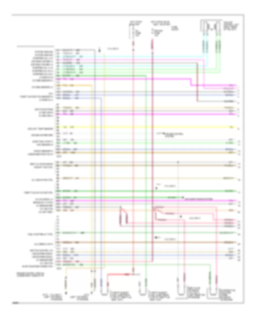
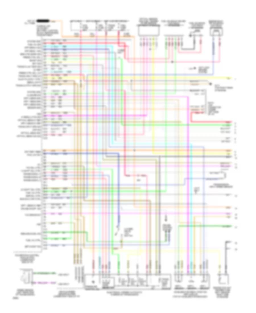
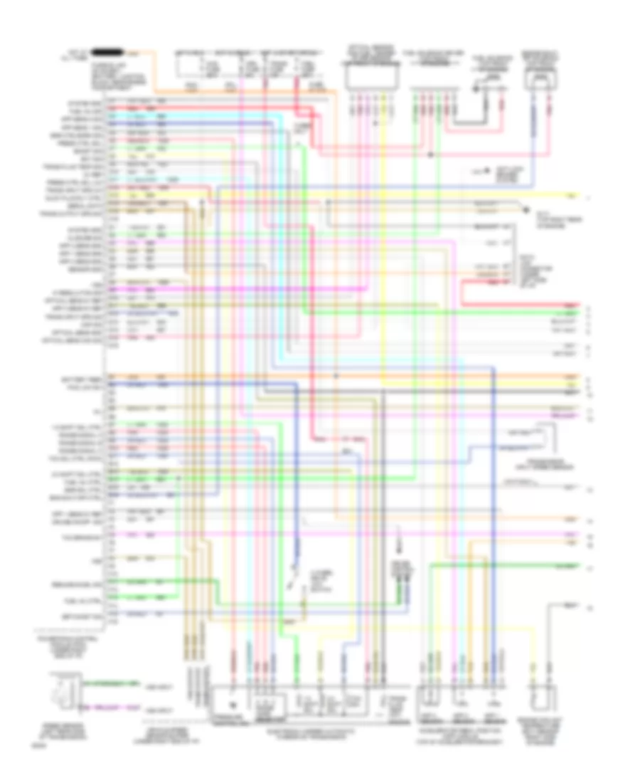
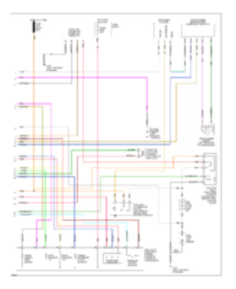
6.5L (VIN F), Engine Performance Wiring Diagrams, 4L60E A/T (1 of 2) for GMC Pickup C1994 2500
List of elements for 6.5L (VIN F), Engine Performance Wiring Diagrams, 4L60E A/T (1 of 2) for GMC Pickup C1994 2500:
- 1-2 shift sol
- 1-2 shift sol ctrl
- 2-3 shift sol
- 2-3 shift sol ctrl
- 3-2 shift sol
- 4 wheel drive low switch
- 4wd fuse 25a
- 5v ref
- A range mode selector
- Accelerator pedal position (app) module (top of accelerator bracket)
- Anti-lock brakes system
- App 1 sens 5v ref
- App 1 sens gnd
- App 1 sensor
- App 2 sens gnd
- App 2 sensor
- App 3 sens 5v ref
- App 3 sens gnd
- App 3 sensor
- App sens 1 sig
- App sens 2 sig
- B/h
- Battery feed
- Boost sig
- C10
- C11
- C12
- C13
- C14
- C15
- C16
- Ckp sig
- Closure sig
- Crk fuse 5a
- Cruise control system
- Cruise on/off sig
- D10
- D11
- D12
- D13
- D14
- D15
- D16
- Data link connector (under left side of i/p)
- E10
- E11
- E12
- E13
- E14
- E15
- E16
- Ect sig
- Egr ctrl/baro sig
- Egr sol ctrl
- Electronic 4-speed automatic overdrive transmission
- Eng shut-off ctrl
- Engine coolant temperature (ect) sensor (right side of engine)
- Engine shut- off solenoid (top front of engine)
- F/sol fuse 20a
- F10
- F11
- F12
- F13
- F14
- F15
- F16
- Fuel inj ctrl
- Fuel inj sig
- Fuel solenoid (top front of engine)
- Fuel solenoid driver (top front of engine)
- Fuse block
- Fwd low sw
- G117 (top right rear of engine)
- Glow plug rly ctrl
- Hi resolution sig
- Hot at all times
- Hot in crank
- Hot in run
- Hot in start or run
- Mil
- Optical sens 5v ref
- Optical sens cam sig
- Optical sens gnd
- Optical sensor and fuel temper- ature sensor (top front of engine)
- Pnk
- Powertrain control module (pcm) (under right end of i/p)
- Press ctrl sol
- Press ctrl sol (lo)
- Pressure control sol
- Range signal a
- Range signal b
- Range signal c
- Red
- Resume/accel sig
- Sensor gnd
- Serial data
- Set/coast sig
- Speed sensor (left rear side of transmission)
- System gnd
- Tan
- Tcc brake sw
- Tcc sol
- Tcc sol ctrl
- Trans fluid temp (tft) sensor
- Trans fluid temp sig
- Trans fuse 10a
- Trans input spd (hi)
- Trans input spd sig
- Trans output
- Trans output spd sig
- Transmission input speed sensor
- Turbo only
- Vehicle speed sensor buffer (under right end of i/p)
- Vin p only
- Vss
- Vss input
- Vss output
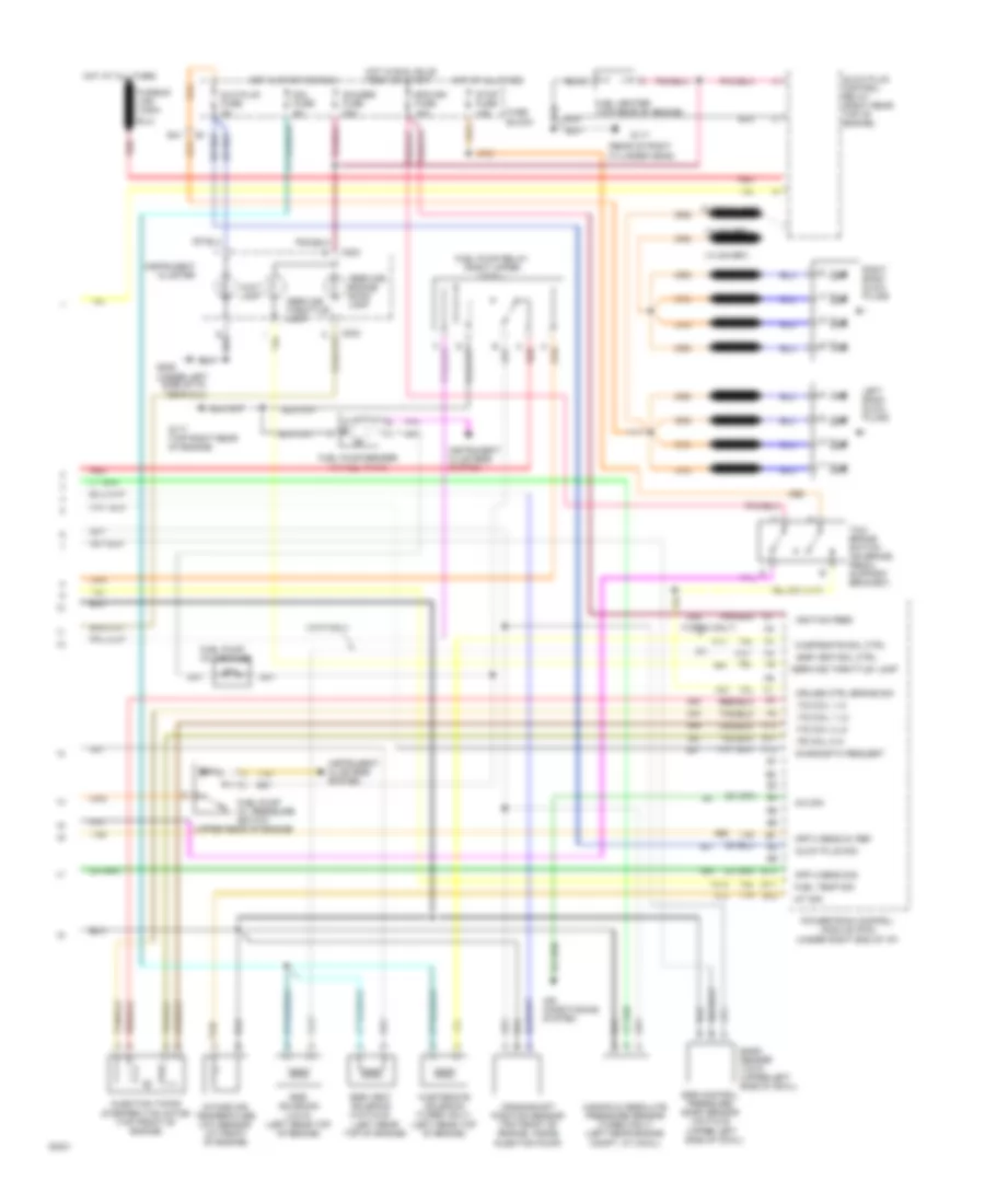
6.5L (VIN F), Engine Performance Wiring Diagrams, 4L60E A/T (2 of 2) for GMC Pickup C1994 2500
List of elements for 6.5L (VIN F), Engine Performance Wiring Diagrams, 4L60E A/T (2 of 2) for GMC Pickup C1994 2500:
- "service engine soon" lamp
- "service throttle" lamp
- (left rear top of engine)
- (rear of right cylinder head)
- (turbo only)
- (under left side of i/p, near dlc)
- (upper rear of engine)
- 2-3 shift sol ctrl
- 20a
- A/c sig
- A10
- A11
- A12
- Air conditioning system
- App 2 sens 5v ref
- App 3 sens sig
- B/h
- B10
- B11
- B12
- Baro sensor (vin f) (upper left side of cowl)
- C red
- C203
- Crankshaft position sensor (top front of engine, inside
- Cruise ctrl brake sig
- Diagnostic request
- Ecm-ign fuse 10a
- Egr control pressure/ baro sensor (vin p & s) (upper left side of cowl)
- Egr solenoid (vin p) (left rear top of engine)
- Egr vent sol ctrl
- Egr vent solenoid (vin p & s)
- Fuel heater (top rear of engine)
- Fuel pump in-line fuse
- Fuel pump oil pressure switch
- Fuel pump relay (right upper cowl)
- Fuel pump/sender (in fuel tank)
- Fuel temp sig
- Fuse block
- Fusible link (12ga-
- Fusible links
- G117
- G117 (top right rear of engine)
- G206
- Gauges fuse 20a
- Glo plug fuse 5a
- Glow plug control relay (right rear top of engine)
- Glow plug sig
- Hot at all times
- Hot in run, bulb test or start
- Hot in start or run
- Iat sig
- Ignition feed
- Injection pump)
- Injection timing stepper (its) motor (top front of engine)
- Instrument cluster
- Instrument clusters system
- Intake air temperature (iat) sensor (at front of engine)
- Its coil 1 hi
- Its coil 1 lo
- Its coil 2 hi
- Its coil 2 lo
- Left bank glow plugs
- Manifold absolute pressure sensor (turbo only) (left rear engine compt, at cowl)
- Powertrain control module (pcm) (under right end of i/p)
- Red
- Right bank glow plugs
- Sol fuse 5a
- Stop fuse 15a
- Tan
- Tcc/ brake switch (on brake pedal support bracket)
- Vin p only
- Wait lamp
- Wastegate sol ctrl
- Wastegate solenoid (turbo only) (left rear top of engine)
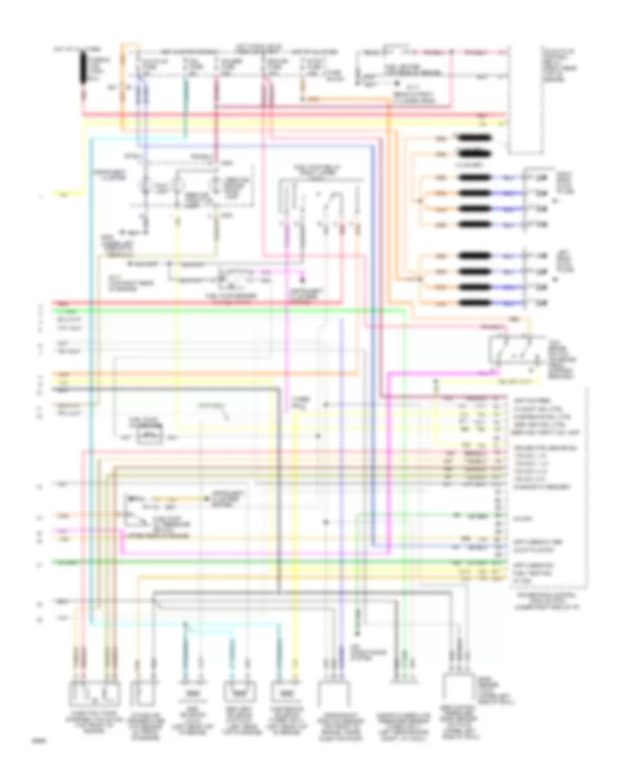
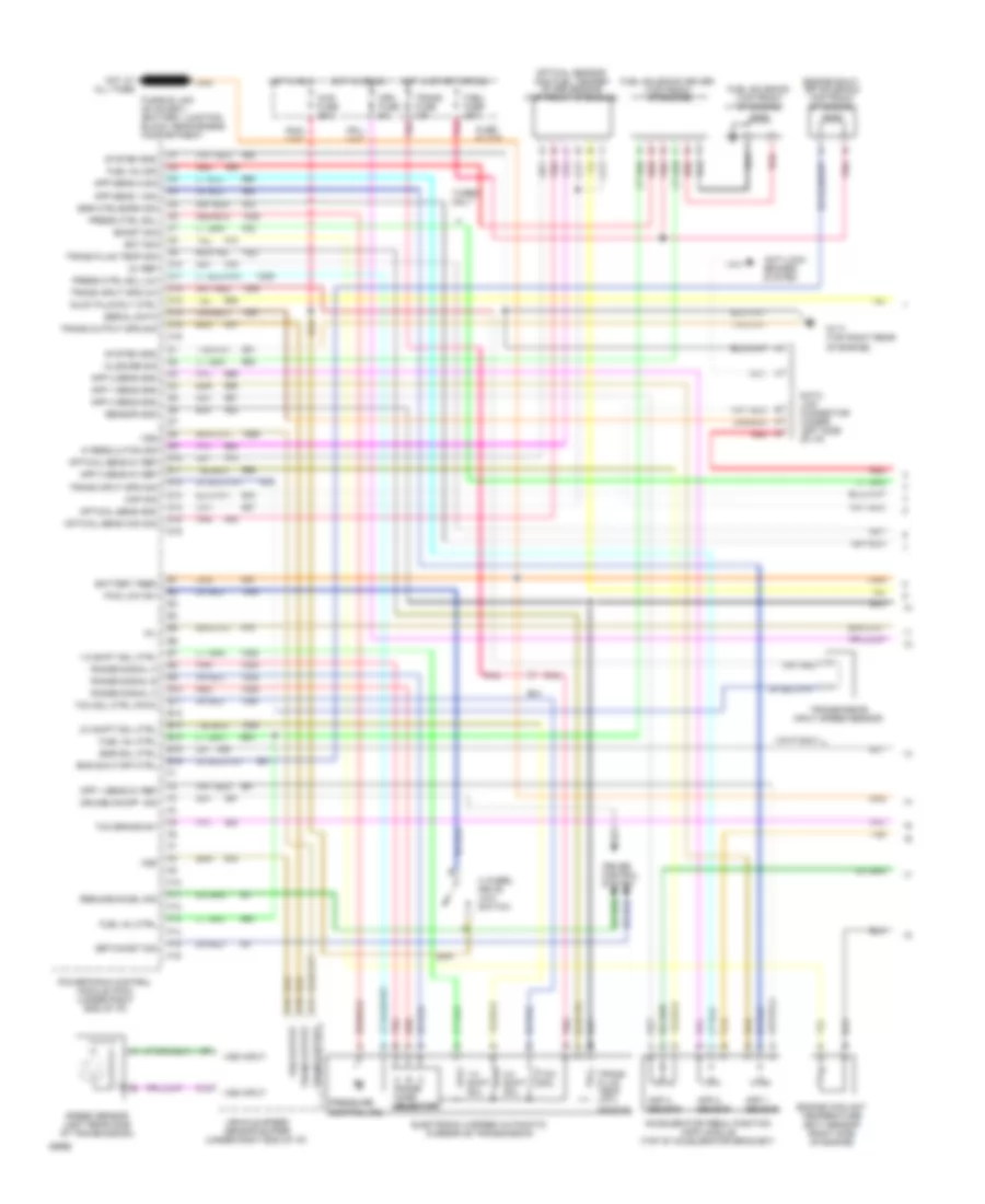
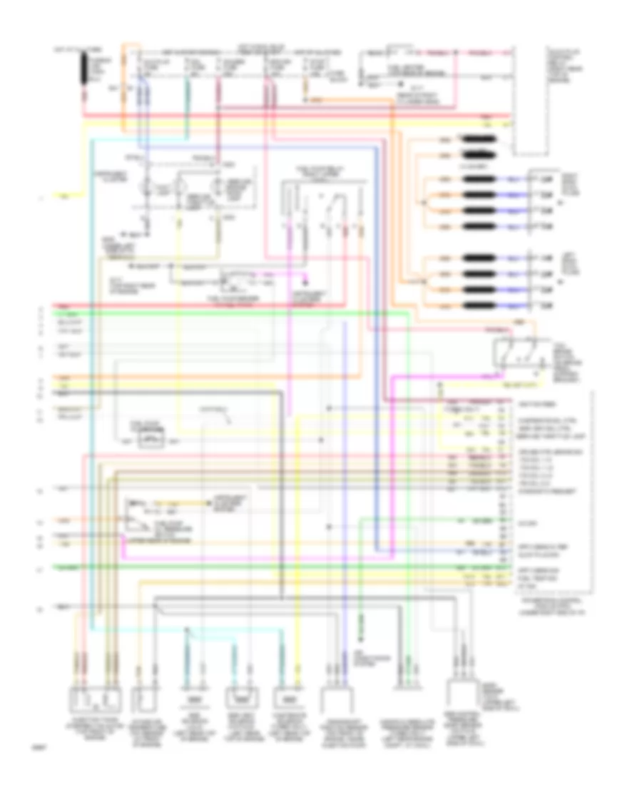
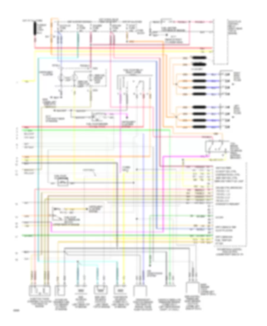
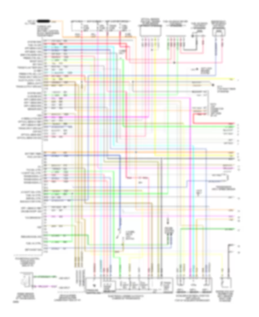
6.5L (VIN F), Engine Performance Wiring Diagrams, 4L80E A/T (1 of 2) for GMC Pickup C1994 2500
List of elements for 6.5L (VIN F), Engine Performance Wiring Diagrams, 4L80E A/T (1 of 2) for GMC Pickup C1994 2500:
- 1-2 shift sol
- 1-2 shift sol ctrl
- 2-3 shift sol
- 2-3 shift sol ctrl
- 4 wheel drive low switch
- 4wd fuse 25a
- 5v ref
- A range mode selector
- Accelerator pedal position (app) module (top of accelerator bracket)
- Anti-lock brakes system
- App 1 sens 5v ref
- App 1 sens gnd
- App 1 sensor
- App 2 sens gnd
- App 2 sensor
- App 3 sens 5v ref
- App 3 sens gnd
- App 3 sensor
- App sens 1 sig
- App sens 2 sig
- B/h
- Battery feed
- Boost sig
- C10
- C11
- C12
- C13
- C14
- C15
- C16
- Ckp sig
- Closure sig
- Crk fuse 5a
- Cruise control system
- Cruise on/off sig
- D10
- D11
- D12
- D13
- D14
- D15
- D16
- Data link connector (under left side of i/p)
- E10
- E11
- E12
- E13
- E14
- E15
- E16
- Ect sig
- Egr ctrl/baro sig
- Egr sol ctrl
- Electronic 4-speed automatic overdrive transmission
- Eng shut-off ctrl
- Engine coolant temperature (ect) sensor (right side of engine)
- Engine shut- off solenoid (top front of engine)
- F/sol fuse 20a
- F10
- F11
- F12
- F13
- F14
- F15
- F16
- Fuel inj ctrl
- Fuel inj sig
- Fuel solenoid (top front of engine)
- Fuel solenoid driver (top front of engine)
- Fuse block
- Fwd low sw
- G117 (top right rear of engine)
- Glow plug rly ctrl
- Hi resolution sig
- Hot at all times
- Hot in crank
- Hot in run
- Hot in start or run
- Mil
- Optical sens 5v ref
- Optical sens cam sig
- Optical sens gnd
- Optical sensor and fuel temper- ature sensor (top front of engine)
- Pnk
- Powertrain control module (pcm) (under right end of i/p)
- Press ctrl sol
- Press ctrl sol (lo)
- Pressure control sol
- Range signal a
- Range signal b
- Range signal c
- Red
- Resume/accel sig
- Sensor gnd
- Serial data
- Set/coast sig
- Speed sensor (left rear side of transmission)
- System gnd
- Tan
- Tcc brake sw
- Tcc sol
- Tcc sol ctrl (pwm)
- Trans fluid temp (tft) sensor
- Trans fluid temp sig
- Trans fuse 10a
- Trans input spd (hi)
- Trans input spd sig
- Trans output
- Trans output spd sig
- Transmission input speed sensor
- Turbo only
- Vehicle speed sensor buffer (under right end of i/p)
- Vin p only
- Vss
- Vss input
- Vss output
6.5L (VIN F), Engine Performance Wiring Diagrams, 4L80E A/T (2 of 2) for GMC Pickup C1994 2500
List of elements for 6.5L (VIN F), Engine Performance Wiring Diagrams, 4L80E A/T (2 of 2) for GMC Pickup C1994 2500:
- "service engine soon" lamp
- "service throttle" lamp
- (left rear top of engine)
- (rear of right cylinder head)
- (turbo only)
- (under left side of i/p, near dlc)
- (upper rear of engine)
- 20a
- A/c sig
- A10
- A11
- A12
- Air conditioning system
- App 2 sens 5v ref
- App 3 sens sig
- B/h
- B10
- B11
- B12
- Baro sensor (vin f) (upper left side of cowl)
- C red
- C203
- Crankshaft position sensor (top front of engine, inside
- Cruise ctrl brake sig
- Diagnostic request
- Ecm-ign fuse 10a
- Egr control pressure/ baro sensor (vin p & s) (upper left side of cowl)
- Egr solenoid (vin p) (left rear top of engine)
- Egr vent sol ctrl
- Egr vent solenoid (vin p & s)
- Fuel heater (top rear of engine)
- Fuel pump in-line fuse
- Fuel pump oil pressure switch
- Fuel pump relay (right upper cowl)
- Fuel pump/sender (in fuel tank)
- Fuel temp sig
- Fuse block
- Fusible link (12ga-
- Fusible links
- G117
- G117 (top right rear of engine)
- G206
- Gauges fuse 20a
- Glo plug fuse 5a
- Glow plug control relay (right rear top of engine)
- Glow plug sig
- Hot at all times
- Hot in run, bulb test or start
- Hot in start or run
- Iat sig
- Ignition feed
- Injection pump)
- Injection timing stepper (its) motor (top front of engine)
- Instrument cluster
- Instrument clusters system
- Intake air temperature (iat) sensor (at front of engine)
- Its coil 1 hi
- Its coil 1 lo
- Its coil 2 hi
- Its coil 2 lo
- Left bank glow plugs
- Manifold absolute pressure sensor (turbo only) (left rear engine compt, at cowl)
- Powertrain control module (pcm) (under right end of i/p)
- Red
- Right bank glow plugs
- Sol fuse 5a
- Stop fuse 15a
- Tan
- Tcc/ brake switch (on brake pedal support bracket)
- Vin p only
- Wait lamp
- Wastegate sol ctrl
- Wastegate solenoid (turbo only) (left rear top of engine)
6.5L (VIN P), Engine Performance Wiring Diagrams, 4L60E A/T (1 of 2) for GMC Pickup C1994 2500
List of elements for 6.5L (VIN P), Engine Performance Wiring Diagrams, 4L60E A/T (1 of 2) for GMC Pickup C1994 2500:
- 1-2 shift sol
- 1-2 shift sol ctrl
- 2-3 shift sol
- 2-3 shift sol ctrl
- 3-2 shift sol
- 4 wheel drive low switch
- 4wd fuse 25a
- 5v ref
- A range mode selector
- Accelerator pedal position (app) module (top of accelerator bracket)
- Anti-lock brakes system
- App 1 sens 5v ref
- App 1 sens gnd
- App 1 sensor
- App 2 sens gnd
- App 2 sensor
- App 3 sens 5v ref
- App 3 sens gnd
- App 3 sensor
- App sens 1 sig
- App sens 2 sig
- B/h
- Battery feed
- Boost sig
- C10
- C11
- C12
- C13
- C14
- C15
- C16
- Ckp sig
- Closure sig
- Crk fuse 5a
- Cruise control system
- Cruise on/off sig
- D10
- D11
- D12
- D13
- D14
- D15
- D16
- Data link connector (under left side of i/p)
- E10
- E11
- E12
- E13
- E14
- E15
- E16
- Ect sig
- Egr ctrl/baro sig
- Egr sol ctrl
- Electronic 4-speed automatic overdrive transmission
- Eng shut-off ctrl
- Engine coolant temperature (ect) sensor (right side of engine)
- Engine shut- off solenoid (top front of engine)
- F/sol fuse 20a
- F10
- F11
- F12
- F13
- F14
- F15
- F16
- Fuel inj ctrl
- Fuel inj sig
- Fuel solenoid (top front of engine)
- Fuel solenoid driver (top front of engine)
- Fuse block
- Fwd low sw
- G117 (top right rear of engine)
- Glow plug rly ctrl
- Hi resolution sig
- Hot at all times
- Hot in crank
- Hot in run
- Hot in start or run
- Mil
- Optical sens 5v ref
- Optical sens cam sig
- Optical sens gnd
- Optical sensor and fuel temper- ature sensor (top front of engine)
- Pnk
- Powertrain control module (pcm) (under right end of i/p)
- Press ctrl sol
- Press ctrl sol (lo)
- Pressure control sol
- Range signal a
- Range signal b
- Range signal c
- Red
- Resume/accel sig
- Sensor gnd
- Serial data
- Set/coast sig
- Speed sensor (left rear side of transmission)
- System gnd
- Tan
- Tcc brake sw
- Tcc sol
- Tcc sol ctrl
- Trans fluid temp (tft) sensor
- Trans fluid temp sig
- Trans fuse 10a
- Trans input spd (hi)
- Trans input spd sig
- Trans output
- Trans output spd sig
- Transmission input speed sensor
- Turbo only
- Vehicle speed sensor buffer (under right end of i/p)
- Vin p only
- Vss
- Vss input
- Vss output
6.5L (VIN P), Engine Performance Wiring Diagrams, 4L60E A/T (2 of 2) for GMC Pickup C1994 2500
List of elements for 6.5L (VIN P), Engine Performance Wiring Diagrams, 4L60E A/T (2 of 2) for GMC Pickup C1994 2500:
- "service engine soon" lamp
- "service throttle" lamp
- (left rear top of engine)
- (rear of right cylinder head)
- (turbo only)
- (under left side of i/p, near dlc)
- (upper rear of engine)
- 2-3 shift sol ctrl
- 20a
- A/c sig
- A10
- A11
- A12
- Air conditioning system
- App 2 sens 5v ref
- App 3 sens sig
- B/h
- B10
- B11
- B12
- Baro sensor (vin f) (upper left side of cowl)
- C red
- C203
- Crankshaft position sensor (top front of engine, inside
- Cruise ctrl brake sig
- Diagnostic request
- Ecm-ign fuse 10a
- Egr control pressure/ baro sensor (vin p & s) (upper left side of cowl)
- Egr solenoid (vin p) (left rear top of engine)
- Egr vent sol ctrl
- Egr vent solenoid (vin p & s)
- Fuel heater (top rear of engine)
- Fuel pump in-line fuse
- Fuel pump oil pressure switch
- Fuel pump relay (right upper cowl)
- Fuel pump/sender (in fuel tank)
- Fuel temp sig
- Fuse block
- Fusible link (12ga-
- Fusible links
- G117
- G117 (top right rear of engine)
- G206
- Gauges fuse 20a
- Glo plug fuse 5a
- Glow plug control relay (right rear top of engine)
- Glow plug sig
- Hot at all times
- Hot in run, bulb test or start
- Hot in start or run
- Iat sig
- Ignition feed
- Injection pump)
- Injection timing stepper (its) motor (top front of engine)
- Instrument cluster
- Instrument clusters system
- Intake air temperature (iat) sensor (at front of engine)
- Its coil 1 hi
- Its coil 1 lo
- Its coil 2 hi
- Its coil 2 lo
- Left bank glow plugs
- Manifold absolute pressure sensor (turbo only) (left rear engine compt, at cowl)
- Powertrain control module (pcm) (under right end of i/p)
- Red
- Right bank glow plugs
- Sol fuse 5a
- Stop fuse 15a
- Tan
- Tcc/ brake switch (on brake pedal support bracket)
- Vin p only
- Wait lamp
- Wastegate sol ctrl
- Wastegate solenoid (turbo only) (left rear top of engine)
6.5L (VIN P), Engine Performance Wiring Diagrams, 4L80E A/T (1 of 2) for GMC Pickup C1994 2500
List of elements for 6.5L (VIN P), Engine Performance Wiring Diagrams, 4L80E A/T (1 of 2) for GMC Pickup C1994 2500:
- 1-2 shift sol
- 1-2 shift sol ctrl
- 2-3 shift sol
- 2-3 shift sol ctrl
- 4 wheel drive low switch
- 4wd fuse 25a
- 5v ref
- A range mode selector
- Accelerator pedal position (app) module (top of accelerator bracket)
- Anti-lock brakes system
- App 1 sens 5v ref
- App 1 sens gnd
- App 1 sensor
- App 2 sens gnd
- App 2 sensor
- App 3 sens 5v ref
- App 3 sens gnd
- App 3 sensor
- App sens 1 sig
- App sens 2 sig
- B/h
- Battery feed
- Boost sig
- C10
- C11
- C12
- C13
- C14
- C15
- C16
- Ckp sig
- Closure sig
- Crk fuse 5a
- Cruise control system
- Cruise on/off sig
- D10
- D11
- D12
- D13
- D14
- D15
- D16
- Data link connector (under left side of i/p)
- E10
- E11
- E12
- E13
- E14
- E15
- E16
- Ect sig
- Egr ctrl/baro sig
- Egr sol ctrl
- Electronic 4-speed automatic overdrive transmission
- Eng shut-off ctrl
- Engine coolant temperature (ect) sensor (right side of engine)
- Engine shut- off solenoid (top front of engine)
- F/sol fuse 20a
- F10
- F11
- F12
- F13
- F14
- F15
- F16
- Fuel inj ctrl
- Fuel inj sig
- Fuel solenoid (top front of engine)
- Fuel solenoid driver (top front of engine)
- Fuse block
- Fwd low sw
- G117 (top right rear of engine)
- Glow plug rly ctrl
- Hi resolution sig
- Hot at all times
- Hot in crank
- Hot in run
- Hot in start or run
- Mil
- Optical sens 5v ref
- Optical sens cam sig
- Optical sens gnd
- Optical sensor and fuel temper- ature sensor (top front of engine)
- Pnk
- Powertrain control module (pcm) (under right end of i/p)
- Press ctrl sol
- Press ctrl sol (lo)
- Pressure control sol
- Range signal a
- Range signal b
- Range signal c
- Red
- Resume/accel sig
- Sensor gnd
- Serial data
- Set/coast sig
- Speed sensor (left rear side of transmission)
- System gnd
- Tan
- Tcc brake sw
- Tcc sol
- Tcc sol ctrl (pwm)
- Trans fluid temp (tft) sensor
- Trans fluid temp sig
- Trans fuse 10a
- Trans input spd (hi)
- Trans input spd sig
- Trans output
- Trans output spd sig
- Transmission input speed sensor
- Turbo only
- Vehicle speed sensor buffer (under right end of i/p)
- Vin p only
- Vss
- Vss input
- Vss output
6.5L (VIN P), Engine Performance Wiring Diagrams, 4L80E A/T (2 of 2) for GMC Pickup C1994 2500
List of elements for 6.5L (VIN P), Engine Performance Wiring Diagrams, 4L80E A/T (2 of 2) for GMC Pickup C1994 2500:
- "service engine soon" lamp
- "service throttle" lamp
- (left rear top of engine)
- (rear of right cylinder head)
- (turbo only)
- (under left side of i/p, near dlc)
- (upper rear of engine)
- 20a
- A/c sig
- A10
- A11
- A12
- Air conditioning system
- App 2 sens 5v ref
- App 3 sens sig
- B/h
- B10
- B11
- B12
- Baro sensor (vin f) (upper left side of cowl)
- C red
- C203
- Crankshaft position sensor (top front of engine, inside
- Cruise ctrl brake sig
- Diagnostic request
- Ecm-ign fuse 10a
- Egr control pressure/ baro sensor (vin p & s) (upper left side of cowl)
- Egr solenoid (vin p) (left rear top of engine)
- Egr vent sol ctrl
- Egr vent solenoid (vin p & s)
- Fuel heater (top rear of engine)
- Fuel pump in-line fuse
- Fuel pump oil pressure switch
- Fuel pump relay (right upper cowl)
- Fuel pump/sender (in fuel tank)
- Fuel temp sig
- Fuse block
- Fusible link (12ga-
- Fusible links
- G117
- G117 (top right rear of engine)
- G206
- Gauges fuse 20a
- Glo plug fuse 5a
- Glow plug control relay (right rear top of engine)
- Glow plug sig
- Hot at all times
- Hot in run, bulb test or start
- Hot in start or run
- Iat sig
- Ignition feed
- Injection pump)
- Injection timing stepper (its) motor (top front of engine)
- Instrument cluster
- Instrument clusters system
- Intake air temperature (iat) sensor (at front of engine)
- Its coil 1 hi
- Its coil 1 lo
- Its coil 2 hi
- Its coil 2 lo
- Left bank glow plugs
- Manifold absolute pressure sensor (turbo only) (left rear engine compt, at cowl)
- Powertrain control module (pcm) (under right end of i/p)
- Red
- Right bank glow plugs
- Sol fuse 5a
- Stop fuse 15a
- Tan
- Tcc/ brake switch (on brake pedal support bracket)
- Vin p only
- Wait lamp
- Wastegate sol ctrl
- Wastegate solenoid (turbo only) (left rear top of engine)
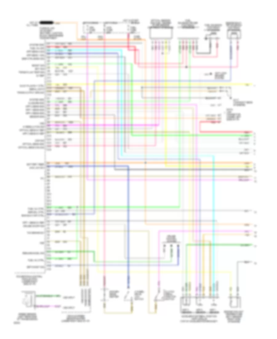
6.5L (VIN P), Engine Performance Wiring Diagrams, M/T (1 of 2) for GMC Pickup C1994 2500
List of elements for 6.5L (VIN P), Engine Performance Wiring Diagrams, M/T (1 of 2) for GMC Pickup C1994 2500:
- 4 wheel drive low switch
- 4wd fuse 25a
- 4wd low sw
- 5v ref
- Accelerator pedal position (app) module (top of accelerator bracket)
- Anti-lock brakes system
- App 1 sens 5v ref
- App 1 sens gnd
- App 1 sensor
- App 2 sens gnd
- App 2 sensor
- App 3 sens 5v ref
- App 3 sens gnd
- App 3 sensor
- App sens 1 sig
- App sens 2 sig
- Battery feed
- Boost sig
- C10
- C11
- C12
- C13
- C14
- C15
- C16
- Ckp sig
- Closure gnd
- Clutch pedal position switch
- Conven- ience center
- Crk fuse 5a
- Cruise control system
- Cruise on/off sig
- D10
- D11
- D12
- D13
- D14
- D15
- D16
- Data link connector (under left side of i/p)
- E10
- E11
- E12
- E13
- E14
- E15
- E16
- Ect sig
- Egr ctrl/baro sig
- Egr sol ctrl
- Eng shut-off ctrl
- Engine coolant temperature (ect) sensor (right side of engine)
- Engine shut- off solenoid (top front of engine)
- F/sol fuse 20a
- F10
- F11
- F12
- F13
- F14
- F15
- F16
- Fuel inj ctrl
- Fuel inj sig
- Fuel solenoid (top front of engine)
- Fuel solenoid driver (top front of engine)
- Fuse block
- G117 (top right rear of engine)
- Glow plug rly ctrl
- Hi resolution sig
- Hot at all times
- Hot in crank
- Hot in run
- Hot in start
- Mil
- Optical sens 5v ref
- Optical sens cam sig
- Optical sens gnd
- Optical sensor and fuel temper- ature sensor (top front of engine)
- Or run
- Pnk
- Powertrain control module (pcm) (under right end of i/p)
- Red
- Resume/accel sig
- Sensor gnd
- Serial data
- Set/coast sig
- Speed sensor (left rear side of transmission)
- System gnd
- Tan
- Tcc brake sw
- Trans fluid temp sig
- Trans output
- Trans output spd sig
- Vehicle speed sensor buffer (under right end of i/p)
- Vss
- Vss input
- Vss output
6.5L (VIN P), Engine Performance Wiring Diagrams, M/T (2 of 2) for GMC Pickup C1994 2500
List of elements for 6.5L (VIN P), Engine Performance Wiring Diagrams, M/T (2 of 2) for GMC Pickup C1994 2500:
- "service throttle" lamp
- 'service engine soon' lamp
- 'service throttle' lamp
- 'wait' lamp
- (upper rear of engine)
- 20a
- A/c sig
- A10
- A11
- A12
- Air cond- itioning system
- App 2 sens 5v ref
- App 3 sens sig
- B/h
- B10
- B11
- B12
- Baro sensor (vin f only) (upper left
- C red
- C203
- Crankshaft position sensor (top front of engine, inside
- Cruise ctrl brake sig
- Diagnostic request
- Ecm-ign fuse 10a
- Egr control pressure/ baro sensor (vin p & s) (upper left side of cowl)
- Egr solenoid (vin p only) (left rear top of engine)
- Egr vent sol ctrl
- Egr vent solenoid (vin p & s) (left rear top of engine)
- Fuel heater (top rear of engine)
- Fuel pump in-line fuse
- Fuel pump oil pressure switch
- Fuel pump relay (right side of safety wall)
- Fuel pump/sender (in fuel tank)
- Fuel temp sig
- Fuse block
- Fusible link (12ga-
- Fusible links
- G117 (rear of right cylinder head)
- G117 (top right rear of engine)
- G206 (under left side of i/p, near dlc)
- Gauges fuse 20a
- Glo plug fuse 5a
- Glow plug control relay (right rear top of engine)
- Glow plug sig
- Hot at all times
- Hot in run, bulb test or start
- Hot in start or run
- Iat sig
- Ignition feed
- Injection pump)
- Injection timing stepper (its) motor (top front of engine)
- Instrument cluster
- Instrument clusters system
- Intake air temperature (iat) sensor (at front of engine)
- Its coil 1 hi
- Its coil 1 lo
- Its coil 2 hi
- Its coil 2 lo
- Left bank glow plugs
- Manifold absolute pressure sensor (vin f & s) (left rear engine compt, at cowl)
- Powertrain control module (pcm) (under right end of i/p)
- Red
- Right bank glow plugs
- Side of cowl)
- Sol fuse 5a
- Stop fuse 15a
- Tan
- Tcc/ brake switch (on brake pedal support bracket)
- Wastegate sol ctrl
- Wastegate solenoid (vin f only) (left rear top of engine)
6.5L (VIN S), Engine Performance Wiring Diagrams, 4L60E A/T (1 of 2) for GMC Pickup C1994 2500
List of elements for 6.5L (VIN S), Engine Performance Wiring Diagrams, 4L60E A/T (1 of 2) for GMC Pickup C1994 2500:
- 1-2 shift sol
- 1-2 shift sol ctrl
- 2-3 shift sol
- 2-3 shift sol ctrl
- 3-2 shift sol
- 4 wheel drive low switch
- 4wd fuse 25a
- 5v ref
- A range mode selector
- Accelerator pedal position (app) module (top of accelerator bracket)
- Anti-lock brakes system
- App 1 sens 5v ref
- App 1 sens gnd
- App 1 sensor
- App 2 sens gnd
- App 2 sensor
- App 3 sens 5v ref
- App 3 sens gnd
- App 3 sensor
- App sens 1 sig
- App sens 2 sig
- B/h
- Battery feed
- Boost sig
- C10
- C11
- C12
- C13
- C14
- C15
- C16
- Ckp sig
- Closure sig
- Crk fuse 5a
- Cruise control system
- Cruise on/off sig
- D10
- D11
- D12
- D13
- D14
- D15
- D16
- Data link connector (under left side of i/p)
- E10
- E11
- E12
- E13
- E14
- E15
- E16
- Ect sig
- Egr ctrl/baro sig
- Egr sol ctrl
- Electronic 4-speed automatic overdrive transmission
- Eng shut-off ctrl
- Engine coolant temperature (ect) sensor (right side of engine)
- Engine shut- off solenoid (top front of engine)
- F/sol fuse 20a
- F10
- F11
- F12
- F13
- F14
- F15
- F16
- Fuel inj ctrl
- Fuel inj sig
- Fuel solenoid (top front of engine)
- Fuel solenoid driver (top front of engine)
- Fuse block
- Fwd low sw
- G117 (top right rear of engine)
- Glow plug rly ctrl
- Hi resolution sig
- Hot at all times
- Hot in crank
- Hot in run
- Hot in start or run
- Mil
- Optical sens 5v ref
- Optical sens cam sig
- Optical sens gnd
- Optical sensor and fuel temper- ature sensor (top front of engine)
- Pnk
- Powertrain control module (pcm) (under right end of i/p)
- Press ctrl sol
- Press ctrl sol (lo)
- Pressure control sol
- Range signal a
- Range signal b
- Range signal c
- Red
- Resume/accel sig
- Sensor gnd
- Serial data
- Set/coast sig
- Speed sensor (left rear side of transmission)
- System gnd
- Tan
- Tcc brake sw
- Tcc sol
- Tcc sol ctrl
- Trans fluid temp (tft) sensor
- Trans fluid temp sig
- Trans fuse 10a
- Trans input spd (hi)
- Trans input spd sig
- Trans output
- Trans output spd sig
- Transmission input speed sensor
- Turbo only
- Vehicle speed sensor buffer (under right end of i/p)
- Vin p only
- Vss
- Vss input
- Vss output
6.5L (VIN S), Engine Performance Wiring Diagrams, 4L60E A/T (2 of 2) for GMC Pickup C1994 2500
List of elements for 6.5L (VIN S), Engine Performance Wiring Diagrams, 4L60E A/T (2 of 2) for GMC Pickup C1994 2500:
- "service engine soon" lamp
- "service throttle" lamp
- (left rear top of engine)
- (rear of right cylinder head)
- (turbo only)
- (under left side of i/p, near dlc)
- (upper rear of engine)
- 2-3 shift sol ctrl
- 20a
- A/c sig
- A10
- A11
- A12
- Air conditioning system
- App 2 sens 5v ref
- App 3 sens sig
- B/h
- B10
- B11
- B12
- Baro sensor (vin f) (upper left side of cowl)
- C red
- C203
- Crankshaft position sensor (top front of engine, inside
- Cruise ctrl brake sig
- Diagnostic request
- Ecm-ign fuse 10a
- Egr control pressure/ baro sensor (vin p & s) (upper left side of cowl)
- Egr solenoid (vin p) (left rear top of engine)
- Egr vent sol ctrl
- Egr vent solenoid (vin p & s)
- Fuel heater (top rear of engine)
- Fuel pump in-line fuse
- Fuel pump oil pressure switch
- Fuel pump relay (right upper cowl)
- Fuel pump/sender (in fuel tank)
- Fuel temp sig
- Fuse block
- Fusible link (12ga-
- Fusible links
- G117
- G117 (top right rear of engine)
- G206
- Gauges fuse 20a
- Glo plug fuse 5a
- Glow plug control relay (right rear top of engine)
- Glow plug sig
- Hot at all times
- Hot in run, bulb test or start
- Hot in start or run
- Iat sig
- Ignition feed
- Injection pump)
- Injection timing stepper (its) motor (top front of engine)
- Instrument cluster
- Instrument clusters system
- Intake air temperature (iat) sensor (at front of engine)
- Its coil 1 hi
- Its coil 1 lo
- Its coil 2 hi
- Its coil 2 lo
- Left bank glow plugs
- Manifold absolute pressure sensor (turbo only) (left rear engine compt, at cowl)
- Powertrain control module (pcm) (under right end of i/p)
- Red
- Right bank glow plugs
- Sol fuse 5a
- Stop fuse 15a
- Tan
- Tcc/ brake switch (on brake pedal support bracket)
- Vin p only
- Wait lamp
- Wastegate sol ctrl
- Wastegate solenoid (turbo only) (left rear top of engine)
6.5L (VIN S), Engine Performance Wiring Diagrams, 4L80E A/T (1 of 2) for GMC Pickup C1994 2500
List of elements for 6.5L (VIN S), Engine Performance Wiring Diagrams, 4L80E A/T (1 of 2) for GMC Pickup C1994 2500:
- 1-2 shift sol
- 1-2 shift sol ctrl
- 2-3 shift sol
- 2-3 shift sol ctrl
- 4 wheel drive low switch
- 4wd fuse 25a
- 5v ref
- A range mode selector
- Accelerator pedal position (app) module (top of accelerator bracket)
- Anti-lock brakes system
- App 1 sens 5v ref
- App 1 sens gnd
- App 1 sensor
- App 2 sens gnd
- App 2 sensor
- App 3 sens 5v ref
- App 3 sens gnd
- App 3 sensor
- App sens 1 sig
- App sens 2 sig
- B/h
- Battery feed
- Boost sig
- C10
- C11
- C12
- C13
- C14
- C15
- C16
- Ckp sig
- Closure sig
- Crk fuse 5a
- Cruise control system
- Cruise on/off sig
- D10
- D11
- D12
- D13
- D14
- D15
- D16
- Data link connector (under left side of i/p)
- E10
- E11
- E12
- E13
- E14
- E15
- E16
- Ect sig
- Egr ctrl/baro sig
- Egr sol ctrl
- Electronic 4-speed automatic overdrive transmission
- Eng shut-off ctrl
- Engine coolant temperature (ect) sensor (right side of engine)
- Engine shut- off solenoid (top front of engine)
- F/sol fuse 20a
- F10
- F11
- F12
- F13
- F14
- F15
- F16
- Fuel inj ctrl
- Fuel inj sig
- Fuel solenoid (top front of engine)
- Fuel solenoid driver (top front of engine)
- Fuse block
- Fwd low sw
- G117 (top right rear of engine)
- Glow plug rly ctrl
- Hi resolution sig
- Hot at all times
- Hot in crank
- Hot in run
- Hot in start or run
- Mil
- Optical sens 5v ref
- Optical sens cam sig
- Optical sens gnd
- Optical sensor and fuel temper- ature sensor (top front of engine)
- Pnk
- Powertrain control module (pcm) (under right end of i/p)
- Press ctrl sol
- Press ctrl sol (lo)
- Pressure control sol
- Range signal a
- Range signal b
- Range signal c
- Red
- Resume/accel sig
- Sensor gnd
- Serial data
- Set/coast sig
- Speed sensor (left rear side of transmission)
- System gnd
- Tan
- Tcc brake sw
- Tcc sol
- Tcc sol ctrl (pwm)
- Trans fluid temp (tft) sensor
- Trans fluid temp sig
- Trans fuse 10a
- Trans input spd (hi)
- Trans input spd sig
- Trans output
- Trans output spd sig
- Transmission input speed sensor
- Turbo only
- Vehicle speed sensor buffer (under right end of i/p)
- Vin p only
- Vss
- Vss input
- Vss output
6.5L (VIN S), Engine Performance Wiring Diagrams, 4L80E A/T (2 of 2) for GMC Pickup C1994 2500
List of elements for 6.5L (VIN S), Engine Performance Wiring Diagrams, 4L80E A/T (2 of 2) for GMC Pickup C1994 2500:
- "service engine soon" lamp
- "service throttle" lamp
- (left rear top of engine)
- (rear of right cylinder head)
- (turbo only)
- (under left side of i/p, near dlc)
- (upper rear of engine)
- 20a
- A/c sig
- A10
- A11
- A12
- Air conditioning system
- App 2 sens 5v ref
- App 3 sens sig
- B/h
- B10
- B11
- B12
- Baro sensor (vin f) (upper left side of cowl)
- C red
- C203
- Crankshaft position sensor (top front of engine, inside
- Cruise ctrl brake sig
- Diagnostic request
- Ecm-ign fuse 10a
- Egr control pressure/ baro sensor (vin p & s) (upper left side of cowl)
- Egr solenoid (vin p) (left rear top of engine)
- Egr vent sol ctrl
- Egr vent solenoid (vin p & s)
- Fuel heater (top rear of engine)
- Fuel pump in-line fuse
- Fuel pump oil pressure switch
- Fuel pump relay (right upper cowl)
- Fuel pump/sender (in fuel tank)
- Fuel temp sig
- Fuse block
- Fusible link (12ga-
- Fusible links
- G117
- G117 (top right rear of engine)
- G206
- Gauges fuse 20a
- Glo plug fuse 5a
- Glow plug control relay (right rear top of engine)
- Glow plug sig
- Hot at all times
- Hot in run, bulb test or start
- Hot in start or run
- Iat sig
- Ignition feed
- Injection pump)
- Injection timing stepper (its) motor (top front of engine)
- Instrument cluster
- Instrument clusters system
- Intake air temperature (iat) sensor (at front of engine)
- Its coil 1 hi
- Its coil 1 lo
- Its coil 2 hi
- Its coil 2 lo
- Left bank glow plugs
- Manifold absolute pressure sensor (turbo only) (left rear engine compt, at cowl)
- Powertrain control module (pcm) (under right end of i/p)
- Red
- Right bank glow plugs
- Sol fuse 5a
- Stop fuse 15a
- Tan
- Tcc/ brake switch (on brake pedal support bracket)
- Vin p only
- Wait lamp
- Wastegate sol ctrl
- Wastegate solenoid (turbo only) (left rear top of engine)
6.5L (VIN S), Engine Performance Wiring Diagrams, M/T (1 of 2) for GMC Pickup C1994 2500
List of elements for 6.5L (VIN S), Engine Performance Wiring Diagrams, M/T (1 of 2) for GMC Pickup C1994 2500:
- 4 wheel drive low switch
- 4wd fuse 25a
- 4wd low sw
- 5v ref
- Accelerator pedal position (app) module (top of accelerator bracket)
- Anti-lock brakes system
- App 1 sens 5v ref
- App 1 sens gnd
- App 1 sensor
- App 2 sens gnd
- App 2 sensor
- App 3 sens 5v ref
- App 3 sens gnd
- App 3 sensor
- App sens 1 sig
- App sens 2 sig
- Battery feed
- Boost sig
- C10
- C11
- C12
- C13
- C14
- C15
- C16
- Ckp sig
- Closure gnd
- Clutch pedal position switch
- Conven- ience center
- Crk fuse 5a
- Cruise control system
- Cruise on/off sig
- D10
- D11
- D12
- D13
- D14
- D15
- D16
- Data link connector (under left side of i/p)
- E10
- E11
- E12
- E13
- E14
- E15
- E16
- Ect sig
- Egr ctrl/baro sig
- Egr sol ctrl
- Eng shut-off ctrl
- Engine coolant temperature (ect) sensor (right side of engine)
- Engine shut- off solenoid (top front of engine)
- F/sol fuse 20a
- F10
- F11
- F12
- F13
- F14
- F15
- F16
- Fuel inj ctrl
- Fuel inj sig
- Fuel solenoid (top front of engine)
- Fuel solenoid driver (top front of engine)
- Fuse block
- G117 (top right rear of engine)
- Glow plug rly ctrl
- Hi resolution sig
- Hot at all times
- Hot in crank
- Hot in run
- Hot in start
- Mil
- Optical sens 5v ref
- Optical sens cam sig
- Optical sens gnd
- Optical sensor and fuel temper- ature sensor (top front of engine)
- Or run
- Pnk
- Powertrain control module (pcm) (under right end of i/p)
- Red
- Resume/accel sig
- Sensor gnd
- Serial data
- Set/coast sig
- Speed sensor (left rear side of transmission)
- System gnd
- Tan
- Tcc brake sw
- Trans fluid temp sig
- Trans output
- Trans output spd sig
- Vehicle speed sensor buffer (under right end of i/p)
- Vss
- Vss input
- Vss output
6.5L (VIN S), Engine Performance Wiring Diagrams, M/T (2 of 2) for GMC Pickup C1994 2500
List of elements for 6.5L (VIN S), Engine Performance Wiring Diagrams, M/T (2 of 2) for GMC Pickup C1994 2500:
- "service throttle" lamp
- 'service engine soon' lamp
- 'service throttle' lamp
- 'wait' lamp
- (upper rear of engine)
- 20a
- A/c sig
- A10
- A11
- A12
- Air cond- itioning system
- App 2 sens 5v ref
- App 3 sens sig
- B/h
- B10
- B11
- B12
- Baro sensor (vin f only) (upper left
- C red
- C203
- Crankshaft position sensor (top front of engine, inside
- Cruise ctrl brake sig
- Diagnostic request
- Ecm-ign fuse 10a
- Egr control pressure/ baro sensor (vin p & s) (upper left side of cowl)
- Egr solenoid (vin p only) (left rear top of engine)
- Egr vent sol ctrl
- Egr vent solenoid (vin p & s) (left rear top of engine)
- Fuel heater (top rear of engine)
- Fuel pump in-line fuse
- Fuel pump oil pressure switch
- Fuel pump relay (right side of safety wall)
- Fuel pump/sender (in fuel tank)
- Fuel temp sig
- Fuse block
- Fusible link (12ga-
- Fusible links
- G117 (rear of right cylinder head)
- G117 (top right rear of engine)
- G206 (under left side of i/p, near dlc)
- Gauges fuse 20a
- Glo plug fuse 5a
- Glow plug control relay (right rear top of engine)
- Glow plug sig
- Hot at all times
- Hot in run, bulb test or start
- Hot in start or run
- Iat sig
- Ignition feed
- Injection pump)
- Injection timing stepper (its) motor (top front of engine)
- Instrument cluster
- Instrument clusters system
- Intake air temperature (iat) sensor (at front of engine)
- Its coil 1 hi
- Its coil 1 lo
- Its coil 2 hi
- Its coil 2 lo
- Left bank glow plugs
- Manifold absolute pressure sensor (vin f & s) (left rear engine compt, at cowl)
- Powertrain control module (pcm) (under right end of i/p)
- Red
- Right bank glow plugs
- Side of cowl)
- Sol fuse 5a
- Stop fuse 15a
- Tan
- Tcc/ brake switch (on brake pedal support bracket)
- Wastegate sol ctrl
- Wastegate solenoid (vin f only) (left rear top of engine)
7.4L
7.4L (VIN N), Engine Performance Wiring Diagrams, A/T (1 of 3) for GMC Pickup C1994 2500
List of elements for 7.4L (VIN N), Engine Performance Wiring Diagrams, A/T (1 of 3) for GMC Pickup C1994 2500:
- (left top front
- 12v battery
- 12v ignition
- 5v return a
- 5v return b
- 5v sensor ref
- A/c on signal in
- A10
- A11
- A12
- A13
- A14
- A15
- A16
- Air condition- ing system
- B10
- B11
- B12
- B13
- B14
- B15
- B16
- Brake sw to pcm
- C215
- C218
- Coolant temp sensor
- Cruise control system
- Cruise ind reg grd
- Distributor ref hi
- Distributor ref lo
- Dlc
- Dlc serial data
- E10
- E11
- E12
- E13
- E14
- E15
- E16
- Ecm-ign fuse 10a
- Egr valve solenoid
- Elec fuel pump in
- Engine control module (under right side of i/p)
- Evap canister purge ctrl
- Evaporative canister purge solenoid (on engine)
- F10
- F11
- F12
- F13
- F14
- F15
- F16
- Fuel pump relay ctrl
- Fuse block
- G110
- G110 (left top front of engine)
- Hot in run
- Hot in run, bulb
- Idle air control unit (right rear of tbi unit)
- Ignition bypass
- Ignition control (ic)
- Inj fuse 10a
- Knock sensor in
- Linear egr position in
- Linear egr regulator solenoid valve (right top of engine)
- Lo side inj a
- Lo side inj b
- Map sensor in
- Mil indicator ctrl
- Of engine)
- Or start
- Oxygen sensor hi
- Oxygen sensor lo
- Pcm to trans temp sensor
- Pcm trans force mtr hi
- Pcm trans force mtr lo
- Pcm trans range a
- Pcm trans range b
- Pcm trans range c
- Pcm trans shift sol a
- Pcm trans shift sol b
- Pnk
- Red
- Stepper coil a hi
- Stepper coil a lo
- Stepper coil b hi
- Stepper coil b lo
- System ground
- Tan
- Tcc clutch ctrl
- Test, or start
- Throttle actuator sol ctrl
- Throttle body fuel injector #1 (top of throttle body unit)
- Throttle body fuel injector #2 (top of throttle body unit)
- Throttle position sensor in
- Trans input speed in hi
- Trans input speed in lo
- Transmission input shaft speed sensor (left side of trans- mission)
- Vss buffer signal
7.4L (VIN N), Engine Performance Wiring Diagrams, A/T (2 of 3) for GMC Pickup C1994 2500
List of elements for 7.4L (VIN N), Engine Performance Wiring Diagrams, A/T (2 of 3) for GMC Pickup C1994 2500:
- (center rear
- Accy
- Bulb test
- Distributor
- Engine coolant temperature sensor (right top front of engine)
- Fuse block
- Gauges fuse 20a
- Hot at all times
- Hot in run, bulb test, or start
- Ignition coil (center rear of engine)
- Ignition switch
- Instrument cluster
- Knock sensor (right side of engine, below exhaust manifold)
- Lock
- Manifold absolute pressure sensor (right rear top of engine)
- Nca
- Of engine)
- Off
- Pnk
- Red
- Run
- Service engine soon indicator
- Start
- Tachometer test lead
- Tcc/brake switch (top of brake pedal bracket)
- Throttle position sensor (right side of throttle body)
7.4L (VIN N), Engine Performance Wiring Diagrams, A/T (3 of 3) for GMC Pickup C1994 2500
List of elements for 7.4L (VIN N), Engine Performance Wiring Diagrams, A/T (3 of 3) for GMC Pickup C1994 2500:
- C12
- C13
- C14
- C15
- Cluster
- Data link connector (under left side of i/p)
- Fuel pump and sender
- Fuel pump in-line fuse 20a
- Fuel pump oil pressure switch (left rear of engine, near exhaust manifold)
- Fuel pump relay (right rear of engine compartment, near battery junction block)
- Fuse block
- G110 (left top front of engine)
- Heavy duty electronic 4-speed automatic overdrive transmission
- Hot at all times
- Hot in run or start
- Instrument
- Oil press in
- Oxygen sensor (left exhaust manifold)
- Pnk
- Pressure control solenoid
- Range mode selector
- Red
- Shift solenoid 1-2
- Shift solenoid 2-3
- Tach in
- Tan
- Throttle actuator solenoid (on throttle body unit)
- Torque converter clutch solenoid
- Trans fuse 10a
- Trans- mission temp sensor
- Vehicle speed sensor (left rear side of transmission)
- Vehicle speed sensor buffer (under right end of i/p)
- Vss in
7.4L (VIN N), Engine Performance Wiring Diagrams, M/T (1 of 3) for GMC Pickup C1994 2500
List of elements for 7.4L (VIN N), Engine Performance Wiring Diagrams, M/T (1 of 3) for GMC Pickup C1994 2500:
- (4.3l only)
- (7.4l only)
- (left top front
- 12v battery
- 12v ignition
- 5v return a
- 5v return b
- 5v sensor ref
- A/c on signal in
- A10
- A11
- A12
- A13
- A14
- A15
- A16
- Air conditioning system
- B10
- B11
- B12
- B13
- B14
- B15
- B16
- Brake sw to pcm
- C215
- C218
- Coolant temp sensor
- Cruise control system
- Cruise ind reg grd
- Distributor ref hi
- Distributor ref lo
- Dlc
- Dlc serial data
- E10
- E11
- E12
- E13
- E14
- E15
- E16
- Ecm-ign fuse 10a
- Egr valve solenoid
- Egr valve solenoid (4.3l only) (left rear top of engine)
- Elec fuel pump in
- Engine control module (under right side of i/p)
- Evap canister purge ctrl
- Evaporative canister purge solenoid (on engine)
- F10
- F11
- F12
- F13
- F14
- F15
- F16
- Fuel pump relay ctrl
- Fuse block
- G110
- Hot in run
- Hot in run, bulb
- Idle air control unit (right rear of tbi unit)
- Ignition bypass
- Ignition control (ic)
- Inj fuse 10a
- Knock sensor in
- Linear egr position in
- Lo side inj a
- Lo side inj b
- Map sensor in
- Mil indicator ctrl
- Of engine)
- Or start
- Oxygen sensor hi
- Oxygen sensor lo
- Red
- Stepper coil a hi
- Stepper coil a lo
- Stepper coil b hi
- Stepper coil b lo
- System ground
- Tan
- Test, or start
- Throttle actuator ctrl
- Throttle body fuel injector #1 (top of throttle body unit)
- Throttle body fuel injector #2 (top of throttle body unit)
- Throttle position sensor in
- Upshift ind ctrl
- Vss buffer signal
7.4L (VIN N), Engine Performance Wiring Diagrams, M/T (2 of 3) for GMC Pickup C1994 2500
List of elements for 7.4L (VIN N), Engine Performance Wiring Diagrams, M/T (2 of 3) for GMC Pickup C1994 2500:
- (4.3l only)
- (center rear
- Accy
- Bulb test
- Distributor
- Engine coolant temperature sensor (right top front of engine)
- Fuse block
- Gauges fuse 20a
- Hot at all times
- Hot in run, bulb test, or start
- Ignition coil (center rear of engine)
- Ignition switch
- Instrument cluster
- Knock sensor (4.3l only) (rear of engine)
- Knock sensor (right side of engine, below exhaust manifold)
- Linear egr regulator solenoid valve (7.4l only) (right top of engine)
- Lock
- Manifold absolute pressure sensor (right rear top of engine)
- Nca
- Of engine)
- Off
- Pnk
- Run
- Service engine soon indicator
- Start
- Tachometer test lead
- Tcc/brake switch (top of brake pedal bracket)
- Throttle position sensor (right side of throttle body)
- Up- shift indic- ator
7.4L (VIN N), Engine Performance Wiring Diagrams, M/T (3 of 3) for GMC Pickup C1994 2500
List of elements for 7.4L (VIN N), Engine Performance Wiring Diagrams, M/T (3 of 3) for GMC Pickup C1994 2500:
- (4.3l only)
- (4.3l)
- (7.4l)
- 4wd fuse 25a
- C12
- C13
- C14
- C15
- Cluster
- Data link connector (under left side of i/p)
- Fuel pump and sender
- Fuel pump in-line fuse 20a
- Fuel pump oil pressure switch (left rear of engine, near exhaust manifold)
- Fuel pump relay (right rear of engine compartment, near battery junction block)
- Fuse block
- G110 (left top front of engine)
- G117 (rear of right cylinder head)
- Heated oxygen sensor (4.3l) (in exhaust y-pipe)
- Hot at all times
- Hot in run
- Instrument
- Oil press in
- Oxygen sensor (7.4l) (left exhaust manifold)
- Red
- Tach in
- Tan
- Throttle actuator solenoid (7.4l only) (on throttle body unit)
- Vehicle speed sensor (left rear side of transmission)
- Vehicle speed sensor buffer (under right end of i/p)
- Vss in
EXTERIOR LIGHTS
Exterior Lamps Wiring Diagram for GMC Pickup C1994 2500
List of elements for Exterior Lamps Wiring Diagram for GMC Pickup C1994 2500:
- (chassis cab)
- (in license lamp harness, behind left side of rear bumper) s403
- (left side of engine compartment near headlamp) s105
- (left side)
- (near center high mount stoplamp relay, at left side of eng compartment)
- (pickup)
- (right side)
- (taped to body near fuse block)
- 30a
- Auxiliary lead
- Backup a lamps
- Backup lamps switch (on top of steering column, a/t) (left top of transmission, m/t)
- Battery junction block (in engine compartment, right upper cowl)
- C203
- C271
- Center high mount stoplamp
- Center high mount stoplamp relay
- Chassis cab
- Convenience center (under left side of i/p)
- Crossmember) s426
- Cruise control system
- Fuse block: i/p
- G101 (right inner fender, near battery)
- G106 (on sheet metal, above left headlamp)
- G110 (left top of engine)
- G117 (rear of right) cylinder head)
- G206 (under i/p)
- G409 (left rear frame rail)
- G409 (left side of platform hitch) (rear of left frame rail)
- Hazard
- Hazard flasher (under left side of i/p)
- Head
- Headlight switch assembly
- Heavy duty
- Hot at all times
- Hot in run, bulb test or start
- Inline fuse (near battery junction block)
- Instrument cluster
- Left backup lamp
- Left front marker lamp
- Left front park/turn lamps
- Left tail/stop/ turn lamp
- Left turn indicator
- License lamps
- Normal
- Off
- Park
- Park lps fuse 20a
- Pickup
- Pickup only
- Rear clearance lamps circuit (pickup w/ dual rear wheels)
- Red
- Right backup lamp
- Right front marker lamp
- Right front park/turn lamps
- Right tail/stop/ turn lamp
- Right turn indicator
- Roof marker lamps
- S103
- S104
- S118
- S190
- S207
- S208
- S210 (under left side of dash)
- S251
- S275a (near center high mount stoplamp relay, at left side of eng compartment)
- S404
- S406 (in trailer harness, at rear crossmember)
- S407 (in trailer harness, at rear crossmember)
- S420 (in trailer harness, at rear crossmember)
- S425
- S425 (in rear lamp harness, at left side of rear crossmember)
- S427 (in rear lamp harness, at left side of rear crossmember)
- Stop fuse 15a
- Stoplamp switch (top of brake pedal)
- Terminates for auxiliary usage
- Trailer tow
- Turn left
- Turn right
- Turn signal flasher
- Turn-b/u fuse 15a
- Turn/hazard switch (upper left side of steering switch)
- W/ chassis cab only
Rear Clearance Lamps Wiring Diagram, with Dual Rear Wheels for GMC Pickup C1994 2500
List of elements for Rear Clearance Lamps Wiring Diagram, with Dual Rear Wheels for GMC Pickup C1994 2500:
- (in rear lamp harness, at left side of rear crossmember) s427
- (in trailer wiring harness, at rear crossmember) s405
- Endgate marker lamps
- Front marker & park/turn lamps
- Fuse block: i/p
- G409 (bottom center of endgate)
- G409 (left side of hitch, w/ platform hitch) (left frame rail, w/o platform hitch)
- Head
- Headlight switch assembly
- Hot at all times
- Left front clearance lamp
- Left rear clearance lamp
- Left rear fender
- Off
- Park
- Park lps fuse 20a
- Right front clearance lamp
- Right rear clearance lamp
- Right rear fender
- S208
- S210 (behind left end of dash)
- S425
- Tail/stop/turn & license lamps)
- Trailer tow
GROUND DISTRIBUTION
Ground Distribution Wiring Diagram (1 of 3) for GMC Pickup C1994 2500
List of elements for Ground Distribution Wiring Diagram (1 of 3) for GMC Pickup C1994 2500:
- (4.3l, 5.0l, 5.7l engines)
- (7.4l engine)
- (diesel engines)
- A/c high pressure switch
- Auxiliary cooling fan motor
- Auxilliary battery (gas engines)
- Battery (right)
- Body ground
- Crew cab, suburban & utility vehicles w/ auxilliary lighting
- Crew cab, suburban & utility vehicles w/ overhead console
- Daytime running lamps
- Engine ground
- Front dome & reading lamps
- Front left park and turn lamp
- Front right park and turn lamp
- G# n/a (near rear dome lamps)
- G# n/a (near front dome lamps)
- G# n/a (no location available)
- G101 (right inner fender, near battery)
- G101 (right inner fender, near battery)
- G106 (gasoline engines) (on sheet metal above left headlamp)
- G106 (on sheet metal, above left headlamp)
- G110 (diesel engines) (left top front of engine)
- G119 (front of right cylinder head)
- G119 (right front of engine)
- G119 (right front top of engine)
- G305 (pickup) (right "b" pillar)
- G905 (extended & crew cab) (at right "c" pillar)
- G909 (near front dome lamp)
- Headlights system
- Left battery (diesel engines)
- Left fog lamp
- Left high beam headlamp
- Left high/ low beam headlamp
- Left horn
- Left low beam headlamp
- Left snow- plow lamp, turn signal relay
- Nca
- Overhead roof console lamps
- Rear defogger grid (pickup)
- Rear dome & reading lamps
- Relay
- Right fog lamp
- Right high beam headlamp
- Right high/ low beam headlamp
- Right horn
- Right low beam headlamp
- Right park and turn lamp
- Right snow- plow lamp, turn signal relay
- To g206
- Uncoated
- W/ daytime running lights
- W/ l19 gasoline engine and a/c
- W/ snowplow preparation package
- W/ v22 appearance package
- W/o daytime running lights
- W/o v22 appearance package
- Washer pump motor
- With v22 appearance package
Ground Distribution Wiring Diagram (2 of 3) for GMC Pickup C1994 2500
List of elements for Ground Distribution Wiring Diagram (2 of 3) for GMC Pickup C1994 2500:
- (l05 only) w/ hd automatic transmission
- 4wal module
- 4wal pump motor
- A/c comp- ressor clutch
- A/c controller
- A/c high pressure cutout switch # 2
- A12
- All
- Ash tray lamps
- Audio alarm module
- Auxiliary battery relay
- Blower motor
- C103a
- C159
- C208
- C212
- C228a
- C230a
- C244
- C257
- C287a
- C290
- C86
- Center
- Center high mount stoplamp (chmsl)
- Center high mount stoplamp relay
- Cigarette lighter assembly
- Convenience
- Convenience center
- Coolant level sensor
- Cruise control module
- Data link connector
- Daytime running lamps module
- Daytime running lamps relay
- Diode
- Egr electronic vacuum regulator solenoid valve
- Engine only
- Except drl
- Four- wheel drive indicator
- From left high (or high/low) beam headlamp
- Fuel heater
- Fuel pump and sender
- Fuel pump relay
- G110 (lb4, l19 engines) (left top front of engine)
- G110 (left top front of engine)
- G117 (rear of right cylinder head)
- G125 (l03, l05 engines) top front center of engine)
- G206 (at data link connector)
- Glow plug control module
- Gra
- Ground bus
- Heated oxygen sensor
- I/p comp- artment box lamp
- Instrument cluster
- Lb4, l03, l05, l19 gasoline engines w/ automatic transmission lb4, l19 gasoline engines w/ manual transmission
- Left door jamb switch
- Low coolant warning lamp module
- Nca
- Panel dimmer switch (assembly)
- Park/ neutral position switch
- Pickup only
- Power locks power windows
- Power seat
- Powertrain control module (pcm)
- Radio
- Rear auxilliary heater control
- Rear defogger switch
- Rear washer pump motor
- Rear wiper/ washer switch
- Right door jamb switch
- Roof marker lamps
- Rwal module
- Safety belt retractor switch
- Suburban & utility only
- Tan
- Turn flasher
- Vehicle speed sensor buffer
- W/ diesel engines only
- W/ lb4, l03 & l05 engines
- Water- in- fuel sensor
- Wiper motor and module (front)
Ground Distribution Wiring Diagram (3 of 3) for GMC Pickup C1994 2500
List of elements for Ground Distribution Wiring Diagram (3 of 3) for GMC Pickup C1994 2500:
- (at left rear of frame rail)
- (at left side of hitch)
- (at rear of left frame rail)
- (bottom center of endgate)
- (l05 engine w/hd automatic transmission)
- (top front center of engine)
- (vin k) (w/ manual transmission)
- (w/ platform hitch)
- (w/o platform hitch)
- (w/o platform hitch) (at left rear of frame rail)
- A12
- Auxilliary air condi- tioning (or heater and air conditioning) control (front)
- Auxilliary air condi- tioning (or heater and air conditioning) control (rear)
- Auxilliary heater and air conditioning logic module
- Blower motor (rear)
- Center high mount stoplamp
- Chassis cab
- Convenience center
- Data link connector
- Endgate
- Endgate clearance lamps
- Evrv electronic vacuum regulator valve solenoid
- Fuel pump
- Fuel pump relay
- G110 (left top front of engine)
- G117 (top right rear of engine)
- G125
- G409
- G409 (at left rear of frame rail)
- G409 (at left side of hitch)
- G409 (w/ platform hitch)
- G409 (w/o platform hitch)
- G998 (at right "d" pillar)
- Heavy duty trailer wiring u89
- Hot fuel handling module
- Knock sensor module
- L03, l05 gasoline engines w/ manual transmission
- L49, l56 & l65 diesel engines w/ manual transmission
- Left cargo door defogger grid
- Left door contact switch
- Left front clearance lamp
- Left license lamp
- Left rear clearance lamp
- Left rear fender
- Left rear tail, stop, license, turn and backup lamps
- Left rear tail, stop, turn and backup lamps
- Left tail/ stop, turn and backup lamp
- Liftgate window release solenoid
- Mode door motor
- Orn
- Park/ neutral position switch
- Pickup (w/o dual rear wheels), suburban and utility
- Pickup with dual rear wheels
- Powertrain control module (pcm)
- Rear door jamb switch
- Rear endgate window defogger grid
- Rear wiper motor module
- Right cargo door defogger grid
- Right door contact switch
- Right front clearance lamp
- Right gas strut cylinder
- Right license lamp
- Right rear clearance lamp
- Right rear fender
- Right rear tail, stop, license, turn and backup lamps
- Right rear tail, stop, turn and backup lamps
- Right tail/ stop, turn and backup lamp
- Suburban & utility
- Suburban & utility non-base vehicle
- Suburban & utility w/ automatic transmissions
- Tan
- Temper- ature door motor
- Temper- ature mode door relay
- Trailer
- Vehicle speed sensor buffer
- W/ auxilliary heater & air conditioning
- W/ rear auxilliary heater only
- With endgate
HEADLIGHTS
Headlamps Wiring Diagram, DRL with Composite Lamps for GMC Pickup C1994 2500
List of elements for Headlamps Wiring Diagram, DRL with Composite Lamps for GMC Pickup C1994 2500:
- (at park brake, under left side of i/p)
- Bulb check
- Daytime running lamp indicator
- Daytime running lamps module (behind left side of i/p)
- Daytime running lamps relay (engine compartment front plenum panel)
- Drl fuse 15a
- Fuse block
- G101 (right inner fender, near battery)
- G106 (on sheet metal, above left headlamp)
- G206 (at dlc connector)
- Gauges fuse 20a
- Ground
- Head
- Headlamp dimmer switch
- Headlight switch assembly
- Hi beam feed
- Hi beam indicator
- Hot at all times
- Hot in run
- Hot in run, bulb test or start
- Htr-a/c fuse 25a
- Ignition
- Instrument cluster
- Lamp feed
- Left high beam headlamp
- Left low beam headlamp
- Off
- Output to relay
- Park
- Park brake warning switch
- Pickup only
- Right high beam headlamp
- Right low beam headlamp
- Suburban/ utility only
- Tan
Headlamps Wiring Diagram, DRL with Sealed Beam Lamps for GMC Pickup C1994 2500
List of elements for Headlamps Wiring Diagram, DRL with Sealed Beam Lamps for GMC Pickup C1994 2500:
- (at park brake, under left side of i/p)
- Bulb check
- Daytime running lamp indicator
- Daytime running lamps module (behind left side of i/p)
- Daytime running lamps relay (engine compartment front plenum panel)
- Drl fuse 15a
- Fuse block
- G106 (on sheet metal above left headlamp)
- G107 (on radiator support, behind right headlamp)
- G206 (at dlc connector)
- Gauges fuse 20a
- Ground
- Head
- Headlamp dimmer switch
- Headlight switch assembly
- Hi beam feed
- Hi beam indicator
- Hot at all times
- Hot in run
- Hot in run, bulb test or start
- Htr-a/c fuse 25a
- Ignition
- Instrument cluster
- Lamp feed
- Left headlamp assembly
- Off
- Output to relay
- Park
- Park brake warning switch
- Pickup only
- Right headlamp assembly
- Suburban/ utility only
- Tan
Headlamps Wiring Diagram, with Sealed Beam Lamps for GMC Pickup C1994 2500
List of elements for Headlamps Wiring Diagram, with Sealed Beam Lamps for GMC Pickup C1994 2500:
- G117 (right inner fender near battery)
- G206 (at dcl connector)
- Head
- Headlamp dimmer switch
- Headlight switch assembly
- Hi beam indicator
- Hot at all times
- Instrument cluster
- Left headlamp assembly
- Off
- Park
- Right headlamp assembly
- Tan
Headlamps/Fog Lamps Wiring Diagram, with Composite Lamps for GMC Pickup C1994 2500
List of elements for Headlamps/Fog Lamps Wiring Diagram, with Composite Lamps for GMC Pickup C1994 2500:
- (on sheet metal
- (right inner
- Above left headlamp)
- Acc-batt circuit breaker 30a
- Battery)
- Convenience center (under left side of i/p)
- Fender, near
- Fog lamp on indicator
- Fog lamp relay (behind left side of i/p)
- Fog lamp switch
- Fuse block
- G101
- G101 (right inner fender, near battery)
- G106
- G106 (on sheet metal above left headlamp)
- G206 (at dcl connector)
- Head
- Headlamp dimmer switch
- Headlight switch assembly
- Hi beam indicator
- Hot at all times
- Illum lamp
- Instrument cluster
- Left fog lamp
- Left high beam head- lamp
- Left low beam head- lamp
- Off
- Park
- Pnl lps fuse 5a
- Right fog lamp
- Right high beam head- lamp
- Right low beam head- lamp
- Solid state switch
- Tan
- Variable voltage w/ headlight switch in park or head & rheostat adjusted
HORN
Horn Wiring Diagram for GMC Pickup C1994 2500
List of elements for Horn Wiring Diagram for GMC Pickup C1994 2500:
- (on sheet metal,
- (right inner
- Convenience center (under left side of i/p)
- Fuse block
- G100 above left headlamp)
- G101 fender, near battery)
- Horn relay
- Horn switch
- Hot at all times
- Left horn (at front of vehicle)
- Park lps fuse 20a
- Right horn (at front of vehicle)
- Steering wheel
- W/v22 only
INSTRUMENT CLUSTER
Instrument Cluster Wiring Diagram, Diesel for GMC Pickup C1994 2500
List of elements for Instrument Cluster Wiring Diagram, Diesel for GMC Pickup C1994 2500:
- (behind left
- (behind left side of i/p)
- (front axle
- (front of engine)
- (inside fuel tank)
- (left rear side
- (left top front of engine)
- (right rear
- (turn-hazard
- (under center of i/p)
- (under left side of i/p)
- (under left side of i/p,
- (under left side of i/p, taped to i/p harness)
- (under right side of i/p)
- (w/o drl-dimmer switch; w/ drl-daytime running
- 4-wheel
- 4-wheel abs
- 4-wheel anti-lock brake module (near master cylinder)
- 4wd ind.
- Abs only
- Anti-lock
- Anti-lock brakes ind.
- Audio alarm
- Brake ind.
- Brake module (near master
- Brake pressure warning switch (below master cylinder, at combination valve)
- Center)
- Charge ind.
- Check gauges ind.
- Check gauges lamp driver
- Control module
- Convenience
- Coolant temp.
- Coolant temp. gauge
- Cylinder)
- Daytime
- Daytime running
- Daytime running lamps relay
- Diode
- Diode (behind left side of i/p)
- Drl ind.
- Engine coolant level indicator module
- Engine coolant level sensor (right rear side of radiator)
- Engine coolant temperature sender
- Engine speed
- Engine)
- Exhaust manifold)
- Exterior lights
- Fuel gauge
- Fuel level
- Fuel pump & sender
- Fuel sensor
- Fuse block: i/p
- G110
- G125
- G202
- Gauges fuse 20a
- Generator (left top front of
- Glow plug controller
- Glow plug fuse 5a
- Gnd
- Harness)
- Headlights system
- High beam ind.
- Hot in run, bulb test or start
- Ign
- Ignition switch
- Illum.
- Illum. lamps
- Instrument cluster
- J i
- Lamps module
- Lamps module)
- Left turn ind.
- Low coolant ind.
- Malfunction ind.
- Module
- Of transmission)
- Oil press.
- Oil press. gauge
- Oil pressure switch & sender (left rear of engine, under
- Only
- Over 15,000
- Panel lps fuse 5a
- Park brake warning switch (under left side of i/p)
- Pounds gvw
- Powertrain
- Rear anti-lock brake module (left rear of engine compt)
- Rear wheel abs
- Release relay)
- Right turn ind.
- Running lamps module
- Safety belt ind.
- Service fuel filter ind.
- Service throttle ind.
- Side of i/p, in
- Solenoid switch)
- Solid state
- Speed sensor
- Speedo- meter
- Switch)
- System
- Tacho- meter
- Tailgate release system (endgate window
- Tan
- Taped to i/p
- Top of engine)
- Transmissions
- Twisted pair
- Variable voltage w/ head/park lamps on & dimmer sw adjusted
- Vehicle speed
- Vehicle speed sensor buffer (behind right side of i/p)
- Volt- meter
- W/ 4-wheel
- W/ drl
- W/ drl only
- W/o drl
- Wait-to start ind.
- Water-in
Instrument Cluster Wiring Diagram, Gasoline for GMC Pickup C1994 2500
List of elements for Instrument Cluster Wiring Diagram, Gasoline for GMC Pickup C1994 2500:
- 5.7l(a/t) & 7.4l
- a5-5.0l(m/t) & 5.7l(m/t)
- (behind left
- (behind left side of i/p)
- (center rear
- (front axle
- (inside fuel tank)
- (left rear side
- (left top front of engine)
- (turn-hazard
- (under left side of i/p)
- (under left side of i/p,
- (under left side of i/p, taped to i/p harness)
- (under right side of i/p)
- (w/o drl-dimmer switch; w/ drl-daytime running
- **e2-4.3l & 7.4l a7-5.0l & 5.7l
- *e6-4.3l, 5.0l(a/t),
- 4- wheel abs
- 4-wheel
- 4-wheel anti-lock brake module (near master cylinder)
- 4wd ind.
- Abs only
- Anti-lock
- Anti-lock brakes ind.
- Audio alarm
- Brake ind.
- Brake module (near master
- Brake pressure warning switch (below master cylinder, at combination valve)
- Center)
- Charge ind.
- Check gauges ind.
- Check gauges lamp driver
- Control module
- Convenience
- Coolant temp.
- Coolant temp. gauge
- Cylinder)
- Daytime
- Daytime running
- Daytime running lamps relay
- Diode
- Diode (behind left side of i/p)
- Drl ind.
- Engine coolant temperature sender
- Engine speed
- Engine)
- Exhaust manifold)
- Exterior lights
- Fuel gauge
- Fuel level
- Fuel pump & sender
- Fuse block: i/p
- G110
- G202
- Gauges fuse 20a
- Generator (left top front of
- Gnd
- Harness)
- Headlights system
- High beam ind.
- Hot in run, bulb test or start
- Ign
- Ignition coil
- Ignition switch
- Illum.
- Illum. lamps
- Instrument cluster
- J i
- Lamps module
- Lamps module)
- Left turn ind.
- M/t only
- Malfunction ind.
- Module
- Of engine)
- Of transmission)
- Oil press.
- Oil press. gauge
- Oil pressure switch & sender (left rear of engine, under
- Only
- Over 15,000
- Panel lps fuse 5a
- Park brake warning switch (under left side of i/p)
- Pounds gvw
- Powertrain
- Rear anti-lock brake module (left rear of engine compt)
- Rear wheel abs
- Release relay)
- Right turn ind.
- Running lamps module
- Safety belt ind.
- Side of i/p, in
- Solenoid switch)
- Speed sensor
- Speedo- meter
- Switch)
- System
- Tach test connector
- Tacho- meter
- Tailgate release system (endgate window
- Tan
- Taped to i/p
- Transmissions
- Twisted pair
- Upshift ind.
- Variable voltage w/ head/park lamps on & dimmer sw adjusted
- Vehicle speed
- Vehicle speed sensor buffer (behind right side of i/p)
- Volt- meter
- W/ 4-wheel
- W/ drl
- W/ drl only
- W/o drl
INTERIOR LIGHTS
Courtesy Lamp Wiring Diagram for GMC Pickup C1994 2500
List of elements for Courtesy Lamp Wiring Diagram for GMC Pickup C1994 2500:
- (at dlc )
- (at underhood lamp)
- Battery junction block (right rear engine compartment, at cowl)
- C239a
- Cargo lamp
- Cargo lamp switch
- Convenience center
- Courtesy switch
- Ctsy fuse 20a
- Front dome lamp
- Fuse block
- G127
- G206
- Hot at all times
- In-line fuse 5a (on cowl, near battery junction block)
- Left front door jamb switch
- Panel dimmer switch
- Red
- Right front door jamb switch
- Underhood reel lamp
Courtesy Lamp Wiring Diagram, Crew Cab with Auxiliary Lighting for GMC Pickup C1994 2500
List of elements for Courtesy Lamp Wiring Diagram, Crew Cab with Auxiliary Lighting for GMC Pickup C1994 2500:
- (at dlc)
- (at underhood lamp)
- (near front dome lamp)
- (near rear dome lamp)
- Battery junction block (right rear engine compartment, at cowl)
- C227
- C239a
- C269
- Cargo lamp
- Cargo lamp switch
- Convenience center
- Courtesy switch
- Crew cab only
- Ctsy fuse 20a
- Front dome and reading lamps
- Fuse block
- G127
- G206
- G908
- G909
- Hot at all times
- I/p compartment box lamp a
- In-line fuse 5a (on cowl, near battery junction block)
- Lamp
- Left front door jamb switch
- Left rear door jamb switch
- Nca
- Panel dimmer switch
- Rear dome and reading lamps
- Red
- Right front door jamb switch
- Right i/p courtesy lamp
- Right rear door jamb switch
- Underhood reel lamp
Courtesy Lamp Wiring Diagram, Crew Cab with Overhead Roof Console for GMC Pickup C1994 2500
List of elements for Courtesy Lamp Wiring Diagram, Crew Cab with Overhead Roof Console for GMC Pickup C1994 2500:
- (at dlc )
- (at underhood lamp)
- (near front dome lamp)
- Battery junction block (right rear engine compartment, at cowl)
- C227
- C239a
- Cargo lamp
- Cargo lamp switch
- Convenience center
- Courtesy switch
- Crew cab only
- Crew cab, suburban, utility w/overhead roof console
- Ctsy fuse 20a
- Front dome lamp
- Fuse block
- G127
- G206
- G908
- Hot at all times
- In-line fuse 5a (on cowl, near battery junction block)
- Left front door jamb switch
- Overhead roof console lamps
- Panel dimmer switch
- Rear dome lamp
- Red
- Right front door jamb switch
- Suburban/yukon base
- Underhood reel lamp
Instrument Illumination Wiring Diagram for GMC Pickup C1994 2500
List of elements for Instrument Illumination Wiring Diagram for GMC Pickup C1994 2500:
- (5) bulbs
- (at dlc)
- (at right "d" pillar)
- Ashtray lamp
- Auxiliary a/c-heater front control lamp
- C203
- C206
- C215
- C224
- C258
- Convenience center
- Dim
- Four-wheel drive illumination lamp
- Fuse block
- G206
- G206 (at dlc)
- G998
- Head
- Headlight switch assembly
- Heater a/c control lamps
- Heater control lamps
- High
- Hot at all times
- Instrument cluster
- Light switch
- Off
- Panel dimmer switch assembly
- Park
- Park lp fuse 20a
- Pnl lps fuse 5a
- Radio
- Rear defogger lamp
- Solid state
POWER DISTRIBUTION
Power Distribution Wiring Diagram, Diesel (1 of 4) for GMC Pickup C1994 2500
List of elements for Power Distribution Wiring Diagram, Diesel (1 of 4) for GMC Pickup C1994 2500:
- (pcm)
- 4wal module
- Accy
- Audio alarm module convenience center
- Auxillary cooling fan relay
- Brake switch
- Bulb test
- C10
- C100
- C103a
- C231
- C255
- C256
- Cigarette lighter
- Clutch pedal switch
- Conven- ience center
- Convenience center
- Crank fuse 5a
- Ctsy fuse 20a
- Daytime running lamps relay
- Dome lamp
- Drl fuse 15a
- Ecm-ign, turn b/u & gauges fuses
- Exc. suburban & utility
- Fuel pump relay
- Fuel pump relay
- Fuel pump/oil pressure
- Fuse block
- Fusible
- Fusible link
- G206 (at data link connector)
- Generator
- Glow plug controller
- Glow plugs
- Hazard flasher
- Headlight switch assembly
- High blower relay
- Horn relay convenience center
- Htr-a/c, rr hvac, 4wd & brake fuses
- Ignition switch
- Left battery
- Link
- Lock
- Low blower relay
- Medium blower relay
- Off
- Park lps fuse 20a
- Pnk
- Powertrain control module
- Pwr acc circuit breaker
- Radio
- Rear wheel antilock brake module
- Rear window release relay
- Rear window release switch
- Red
- Right battery
- Rr wpr, frt wpr, rdo fuses and and pwr wdo circuit breaker
- Rst 12ga
- Rst 18ga
- Run
- Start
- Starter motor solenoid
- Stop fuse 15a
- Suburban & utility
- Suburban & utility only
- Switch
- T/g rel fuse 25a
- Trans
- Trans fuse
- W/ auto
- W/ automatic transmission
Power Distribution Wiring Diagram, Diesel (2 of 4) for GMC Pickup C1994 2500
List of elements for Power Distribution Wiring Diagram, Diesel (2 of 4) for GMC Pickup C1994 2500:
- (suburban & crew cab only)
- C241
- C247
- C259
- C276a
- Convenience center
- Frt wpr fuse 25a
- Fuse block
- Fusible link
- Ignition switch
- In-line fuse 3a
- Left front power window switch
- Left power door lock switch
- Left power seat
- Left rear power window switch
- O r g
- Pnk
- Power acc circuit breaker 30a
- Power door lock relay
- Power outside mirror switch
- Pwr wdo circuit breaker 30a
- Radio
- Rdo fuse 10a
- Rear window defogger switch
- Rear wiper/ washer switch
- Red
- Right front power window switch
- Right power door lock switch
- Right rear power window switch
- Rr wpr fuse 25a
- Suburban & utilty only
- W h t
- Wiper motor module
- Wiper washer switch
Power Distribution Wiring Diagram, Diesel (3 of 4) for GMC Pickup C1994 2500
List of elements for Power Distribution Wiring Diagram, Diesel (3 of 4) for GMC Pickup C1994 2500:
- (four wheel antilock)
- (rear wheel antlock)
- 4wd fuse 25a
- A/c clutch relay
- A/c control module
- Antilock brake module
- Auxilliary heater-a/c front control
- Auxilliary heater-a/c logic module
- Auxilliary heater-a/c rear control
- B r n
- Brake fuse 15a
- C1
- C10
- C2
- C5
- Convenience center
- Electronic transmission 4-speed automatic w/overdrive
- Fuse block
- Fusible
- Glow plug control module
- Glow plug fuse 5a
- Heater blower switch
- Heavy duty electronic transmission 4-speed automatic w/overdrive
- High blower relay
- Htr-a/c fuse 25a
- Ignition switch
- Instrument cluster printed ciurcuit
- Interior lights system
- Left glow plugs
- Low blower relay
- Med blower relay
- Mode door motor
- Panel dimmer switch assembly (interior lights system)
- Pnk
- Pnl lps fuse 5a
- Powertrain control module
- R e d
- Right glow plugs
- Rr hvac fuse 25a
- Temp door motor
- Trans fuse 10a
- Transfer case switch
- Vehicle speed sensor buffer module
- W/ air conditioning
Power Distribution Wiring Diagram, Diesel (4 of 4) for GMC Pickup C1994 2500
List of elements for Power Distribution Wiring Diagram, Diesel (4 of 4) for GMC Pickup C1994 2500:
- (l49 & l56 engines only)
- (l56 & l65 only)
- Audio alarm module convenience center
- Auxiliary cooling fan relay
- B l u
- Backup lamp switch
- C278
- C290
- Convenience center
- Cruise control activator switch
- Cruise control module
- Daytime running lamps module (pickup only)
- Daytime running lamps relay
- Ecm-ign fuse 10a
- Egr vent solenoid
- Egr width modulated solenoid
- F/sol fuse 20a
- Fuel heater
- Fuel injection pump
- Fuse block
- Gauges fuse 20a
- Glow plug control module
- Ignition switch
- Instrument cluster printed circuit
- O r g
- Pnk
- Powertrain control module
- Pulse width modulated boost solenoid
- Rear defogger switch
- Sol fuse 5a
- Tcc/ stoplamp switch
- Turn signal flasher
- Turn b/u fuse 15a
- Water-in-fuel sensor
Power Distribution Wiring Diagram, Gasoline (1 of 4) for GMC Pickup C1994 2500
List of elements for Power Distribution Wiring Diagram, Gasoline (1 of 4) for GMC Pickup C1994 2500:
- (pcm)
- 4wal module
- Accy
- Audio alarm module convenience center
- Auxillary cooling fan relay
- Battery
- Brake switch
- Bulb test
- C10
- C103a
- C231
- C255
- C256
- Cigarette lighter
- Clutch pedal switch
- Conven- ience center
- Convenience center
- Crank fuse 5a
- Ctsy fuse 20a
- Daytime running lamps relay
- Dome lamp
- Drl fuse 15a
- Ecm-ign, turn b/u & gauges fuses
- Exc. suburban & utility
- Fuel pump relay
- Fuel pump/oil pressure
- Fuse block
- Fusible
- Fusible link
- G206 (at data link connector)
- Generator
- Hazard flasher
- Headlight switch assembly
- High blower relay
- Horn relay convenience center
- Htr-a/c, rr hvac, 4wd & brake fuses
- Ignition coil
- Ignition switch
- L03 & l05 engines w/ manual transmissions only
- Link
- Lock
- Low blower relay
- Medium blower relay
- Off
- Park lps fuse 20a
- Pnk
- Powertrain control module
- Powertrain control module (pcm)
- Pwr acc circuit breaker
- Radio
- Rear wheel antilock brake module
- Rear window release relay
- Rear window release switch
- Red
- Rr wpr, frt wpr, rdo fuses and and pwr wdo circuit breaker
- Rst 12ga
- Rst 18ga
- Run
- Start
- Starter motor solenoid
- Stop fuse 15a
- Suburban & utility
- Suburban & utility only
- Switch
- T/g rel fuse 25a
- Trans
- Trans & inj fuses
- Vin h&k manual trans only
- W/ auto
- W/ automatic transmission
Power Distribution Wiring Diagram, Gasoline (2 of 4) for GMC Pickup C1994 2500
List of elements for Power Distribution Wiring Diagram, Gasoline (2 of 4) for GMC Pickup C1994 2500:
- (suburban & crew cab only)
- C241
- C247
- C259
- C276a
- Convenience center
- Frt wpr fuse 25a
- Fuse block
- Fusible link
- Ignition switch
- In-line fuse 3a
- Left front power window switch
- Left power door lock switch
- Left power seat
- Left rear power window switch
- O r g
- Pnk
- Power acc circuit breaker 30a
- Power door lock relay
- Power outside mirror switch
- Pwr wdo circuit breaker 30a
- Radio
- Rdo fuse 10a
- Rear window defogger switch
- Rear wiper/ washer switch
- Red
- Right front power window switch
- Right power door lock switch
- Right rear power window switch
- Rr wpr fuse 25a
- Suburban & utilty only
- W h t
- Wiper motor module
- Wiper washer switch
Power Distribution Wiring Diagram, Gasoline (3 of 4) for GMC Pickup C1994 2500
List of elements for Power Distribution Wiring Diagram, Gasoline (3 of 4) for GMC Pickup C1994 2500:
- (four wheel antilock)
- (rear wheel antlock)
- 4wd fuse 25a
- A/c clutch relay
- A/c control module
- Antilock brake module
- Auxilliary battery relay
- Auxilliary heater-a/c front control
- Auxilliary heater-a/c logic module
- Auxilliary heater-a/c rear control
- B r n
- Brake fuse 15a
- C1
- C10
- C2
- C5
- Convenience center
- Electronic transmission 4-speed automatic w/overdrive
- Except vin z
- Fuse block
- Heated oxygen sensor
- Heater blower switch
- Heavy duty electronic transmission 4-speed automatic w/overdrive
- High blower relay
- Htr-a/c fuse 25a
- Ignition switch
- Inj fuse 10a
- Interior lights system
- Low blower relay
- Med blower relay
- Mode door motor
- Panel dimmer switch assembly (interior lights system)
- Pnk
- Pnl lps fuse 5a
- R e d
- Red
- Rr hvac fuse 25a
- Temp door motor
- Throttle body fuel injector a
- Throttle body fuel injector b
- Trans fuse 10a
- Transfer case switch
- Vehicle speed sensor buffer module
- Vin z only
- W/ air conditioning
Power Distribution Wiring Diagram, Gasoline (4 of 4) for GMC Pickup C1994 2500
List of elements for Power Distribution Wiring Diagram, Gasoline (4 of 4) for GMC Pickup C1994 2500:
- (lo3 & lo5 engines, light duty & yukon w/ lo5 engine)
- (suburban & utility only)
- (vin h &k light duty only)
- Air divert solenoid
- Air switching valve solenoid (vin n only)
- Audio alarm module convenience center
- Auxilliary cooling fan relay
- B l u
- Backup lamp switch
- C278
- C290
- Convenience center
- Cruise control activator switch
- Cruise control module
- Daytime running lamps module (pickup only)
- Daytime running lamps relay
- E15
- Ecm-ign fuse 10a
- Esc module
- Evaporative emission canister purge solenoid (w/ nrq)
- Exhaust gas recirculation solenoid valve
- F15
- Fuse block
- Gauges fuse 20a
- Heated oxygen sensor (vins h & k)
- Hot fuel handling module
- Ignition switch
- Instrument cluster printed circuit
- Linear egr regulator valve solenoid (w/ nrq)
- O r g
- Overspeed alarm module
- Pnk
- Powertrain control module
- Rear defogger switch
- Tcc/ stoplamp switch
- Trottle actuator solenoid (vin n only)
- Turn signal flasher convenience center
- Turn b/u fuse 15a
- Vin n only
- Vins h & k only
- Vins h & k w/ automatic transmissions & vins n & z
- Vins h & k w/ manual transmissions
POWER DOOR LOCKS
Door Lock Wiring Diagram, 2 Door for GMC Pickup C1994 2500
List of elements for Door Lock Wiring Diagram, 2 Door for GMC Pickup C1994 2500:
- (under left side of i/p)
- Acc-batt circuit breaker 30a
- Convenience center
- Fuse block
- G206 (at dlc connector)
- H tan
- Hot at all times
- Left front door lock motor
- Left front door lock switch
- Lock
- Right front door lock motor
- Right front door lock switch
- Tan
- Unlock
Door Lock Wiring Diagram, Crew Cab for GMC Pickup C1994 2500
List of elements for Door Lock Wiring Diagram, Crew Cab for GMC Pickup C1994 2500:
- (suburban only)
- Acc-batt circuit breaker 30a
- Contactor right rear cargo door (suburban only)
- Convenience center (under left side of i/p)
- Door lock relay (behind i/p, right side of brake pedal bracket)
- Fuse block
- G206 (at dlc connector)
- Hot at all times
- Left front door lock motor
- Left front door lock switch
- Left rear door lock motor
- Lock
- Power mirror system (in-line fuse)
- Rear cargo door lock motor
- Right front door lock motor
- Right front door lock switch
- Tan
- Unlock
POWER MIRRORS
Power Mirror Wiring Diagram for GMC Pickup C1994 2500
List of elements for Power Mirror Wiring Diagram for GMC Pickup C1994 2500:
-
-
-
- left outside power mirror
- Acc-batt circuit breaker 30a
- Convenience center (under left side of i/p)
- Convenience center (under left side of i/p)
- Down
- Fuse block
- G206 (at dlc connector)
- Hot at all times
- In-line fuse
- Left
- Left/ right motor
- Power outside rearview mirror switch
- Right
- Right outside power mirror
- Up/ down motor
POWER SEATS
Power Seat Wiring Diagrams for GMC Pickup C1994 2500
List of elements for Power Seat Wiring Diagrams for GMC Pickup C1994 2500:
- 30a
- Acc-batt circuit breaker
- Back
- Convenience center (under left side of i/p)
- Down
- Entire seat
- For- ward
- Forward/ rearward motor
- Front height
- Front tilt motor
- Fuse block
- G206 (at dlc connector)
- Hot at all times
- Power seat switch (left side of driver's seat)
- Rear height
- Rear tilt motor
- Tan
POWER WINDOWS
Power Window Wiring Diagram for GMC Pickup C1994 2500
List of elements for Power Window Wiring Diagram for GMC Pickup C1994 2500:
- (under left side of dash)
- Acc-ign circuit breaker (exc 1994) 30a
- C247
- C503
- C507
- Convenience center
- Fuse block
- G206 (at dlc connector)
- Hot in acc or run
- Left front power window motor
- Left front switch
- Left power window master switch
- Pnk
- Pwr-wdo circuit breaker (1994) 30a
- Right front power window motor
- Right front switch
- Right front window switch
- Tan
Power Window Wiring Diagram, Crew Cab for GMC Pickup C1994 2500
List of elements for Power Window Wiring Diagram, Crew Cab for GMC Pickup C1994 2500:
- (at dlc connector)
- (under left side of dash)
- Acc-ign circuit breaker (exc 1994) 30a
- C506
- C507
- Convenience center
- Fuse block
- G206
- Gauges fuse 20a
- Hot in acc or run
- Hot in run or start
- Left front power window motor
- Left front window
- Left rear power window motor
- Left rear window
- Left rear window switch
- Master window switch
- Pnk
- Pwr-wdo circuit breaker (1994) 30a
- Right front power window motor
- Right front window
- Right front window switch
- Right rear power window motor
- Right rear window
- Right rear window switch
- Switch illumination lamp
- Tan
RADIO
2-Speaker System Wiring Diagram for GMC Pickup C1994 2500
List of elements for 2-Speaker System Wiring Diagram for GMC Pickup C1994 2500:
- (ex 1994) (1994)
- (ex. 1991)
- Antenna
- Antenna input
- Coaxial cable
- Ctsy fuse 20a
- Dimmer
- Fuse block (under left side of dash)
- G206 (center of dash)
- Ground
- Hot at all times
- Hot in accy or run
- Ign
- Interior lights system
- Left front speaker
- Lt frt spkr
- Memory(bat)
- Park lamp
- Radio
- Radio fuse 10a 15a
- Right front speaker
- Rt frt spkr
- Tan
AM/FM Stereo for GMC Pickup C1994 2500
List of elements for AM/FM Stereo for GMC Pickup C1994 2500:
- (ex 1994) (1994)
- Antenna
- Antenna out
- Battery
- C243
- C244
- C247
- C248
- C251
- Cassette deck
- Ctsy fuse 20a
- Data
- Dimmer
- Fuse block (under left side of dash)
- G206 (center of dash)
- Graphic equalizer
- Ground
- Hi ground
- Hot at all times
- Hot in accy or run
- Ignition
- Interior lights system
- Left audio
- Left front speaker
- Left rear speaker
- Lf (+)
- Lf (-)
- Lo ground
- Lr (+)
- Lr (-)
- Mem (data)
- Memory
- Mute
- Park lamp
- Pnk
- Power antenna system
- Radio control head
- Radio fuse 10a 15a
- Radio receiver
- Red
- Rf (+)
- Rf (-)
- Right audio
- Right front speaker
- Right rear speaker
- Rr (+)
- Rr (-)
- Tan
- Tape on
- Volt
AM/FM Stereo, with Cassette & Amplifier for GMC Pickup C1994 2500
List of elements for AM/FM Stereo, with Cassette & Amplifier for GMC Pickup C1994 2500:
- (ex 1994) (1994)
- Amplifier relay
- Antenna
- Antenna out
- Battery
- C10
- C11
- C12
- C13
- C14
- C15
- C243
- C244
- C247
- C248
- C251
- Cassette deck
- Convenience center (under left side of dash)
- Ctsy fuse 20a
- Data
- Dimmer
- Fuse block (under left side of dash)
- G206 (center of dash)
- Graphic equalizer
- Ground
- Hi ground
- Hot at all times
- Hot in accy or run
- Ignition
- Interior lights system
- Left audio
- Left front speaker
- Left rear side door speaker
- Left rear speaker
- Lf (+)
- Lf (-)
- Lo ground
- Lr (+)
- Lr (-)
- Lt rr door spkr
- Lt rr spkr
- Mem (data)
- Memory
- Mute
- Not used
- Park lamp
- Pnk
- Power amplifier relay (under dash, left of pedal bracket)
- Radio control head
- Radio fuse 10a 15a
- Radio power amplifier (under driver's seat)
- Radio receiver
- Red
- Rf (+)
- Rf (-)
- Right audio
- Right front speaker
- Right rear side door speaker
- Right rear speaker
- Rr (+)
- Rr (-)
- Rt rr door spkr
- Rt rr spkr
- Tan
- Tape on
- Volt
STARTING/CHARGING
4.3L
4.3L (VIN Z), Charging Wiring Diagram for GMC Pickup C1994 2500
List of elements for 4.3L (VIN Z), Charging Wiring Diagram for GMC Pickup C1994 2500:
- (12 ga. rust)
- (closes with low or high voltage; gen fault)
- (not
- (not used)
- (right front of engine)
- (right inner fender, near battery)
- (top left front of engine)
- Bat
- Battery junction block (right rear of engine compartment, at cowl)
- C109
- C203
- Charge indicator (red)
- Field (rotor)
- Fuse block
- Fusible link
- G101
- G110
- G119
- Gauges fuse 20a
- Generator (top left front of of engine)
- Hot in run, bulb test or start
- Indicators
- Instrument cluster
- Left battery
- Rectifier bridge
- Regulator solid-state
- Right battery
- Starter solenoid (lower right rear of engine, on starter motor)
- Stator
- Sw bat
- Turn on input
- Used)
- Volt sense input
- W/diesel engine
- W/gasoline engine
4.3L (VIN Z), Starting Wiring Diagram for GMC Pickup C1994 2500
List of elements for 4.3L (VIN Z), Starting Wiring Diagram for GMC Pickup C1994 2500:
- (behind left side of instrument panel)
- (lower right side of engine)
- (lower right side of engine, on starter motor)
- (right front of engine)
- (right inner fender,near battery)
- (top left front of engine)
- (with diesel engine)
- Accy
- Battery junction block (right rear of
- Bulb test
- C255
- C256
- Clutch pedal is depressed) (at top of
- Clutch pedal)
- Clutch start switch (normally,open closes when
- Crank fuse
- Engine compartment, at cowl)
- Fuse block
- Fuse block (lower left side of instrument panel)
- Fusible link (12 ga. rust)
- G101
- G110
- G119
- Hold-in winding
- Ignition switch
- Left battery
- Lock
- Off
- Pull-in winding
- Pwr acc circuit breaker 30a
- Red
- Right battery
- Run
- Solenoid contacts
- Start
- Starter motor
- Starter solenoid
- Stop- hz fuse 15a
- W/auto trans
- W/man trans
5.0L
5.0L (VIN H), Charging Wiring Diagram for GMC Pickup C1994 2500
List of elements for 5.0L (VIN H), Charging Wiring Diagram for GMC Pickup C1994 2500:
- (12 ga. rust)
- (closes with low or high voltage; gen fault)
- (not
- (not used)
- (right front of engine)
- (right inner fender, near battery)
- (top left front of engine)
- Bat
- Battery junction block (right rear of engine compartment, at cowl)
- C109
- C203
- Charge indicator (red)
- Field (rotor)
- Fuse block
- Fusible link
- G101
- G110
- G119
- Gauges fuse 20a
- Generator (top left front of of engine)
- Hot in run, bulb test or start
- Indicators
- Instrument cluster
- Left battery
- Rectifier bridge
- Regulator solid-state
- Right battery
- Starter solenoid (lower right rear of engine, on starter motor)
- Stator
- Sw bat
- Turn on input
- Used)
- Volt sense input
- W/diesel engine
- W/gasoline engine
5.0L (VIN H), Starting Wiring Diagram for GMC Pickup C1994 2500
List of elements for 5.0L (VIN H), Starting Wiring Diagram for GMC Pickup C1994 2500:
- (behind left side of instrument panel)
- (lower right side of engine)
- (lower right side of engine, on starter motor)
- (right front of engine)
- (right inner fender,near battery)
- (top left front of engine)
- (with diesel engine)
- Accy
- Battery junction block (right rear of
- Bulb test
- C255
- C256
- Clutch pedal is depressed) (at top of
- Clutch pedal)
- Clutch start switch (normally,open closes when
- Crank fuse
- Engine compartment, at cowl)
- Fuse block
- Fuse block (lower left side of instrument panel)
- Fusible link (12 ga. rust)
- G101
- G110
- G119
- Hold-in winding
- Ignition switch
- Left battery
- Lock
- Off
- Pull-in winding
- Pwr acc circuit breaker 30a
- Red
- Right battery
- Run
- Solenoid contacts
- Start
- Starter motor
- Starter solenoid
- Stop- hz fuse 15a
- W/auto trans
- W/man trans
5.7L
5.7L (VIN K), Charging Wiring Diagram for GMC Pickup C1994 2500
List of elements for 5.7L (VIN K), Charging Wiring Diagram for GMC Pickup C1994 2500:
- (12 ga. rust)
- (closes with low or high voltage; gen fault)
- (not
- (not used)
- (right front of engine)
- (right inner fender, near battery)
- (top left front of engine)
- Bat
- Battery junction block (right rear of engine compartment, at cowl)
- C109
- C203
- Charge indicator (red)
- Field (rotor)
- Fuse block
- Fusible link
- G101
- G110
- G119
- Gauges fuse 20a
- Generator (top left front of of engine)
- Hot in run, bulb test or start
- Indicators
- Instrument cluster
- Left battery
- Rectifier bridge
- Regulator solid-state
- Right battery
- Starter solenoid (lower right rear of engine, on starter motor)
- Stator
- Sw bat
- Turn on input
- Used)
- Volt sense input
- W/diesel engine
- W/gasoline engine
5.7L (VIN K), Starting Wiring Diagram for GMC Pickup C1994 2500
List of elements for 5.7L (VIN K), Starting Wiring Diagram for GMC Pickup C1994 2500:
- (behind left side of instrument panel)
- (lower right side of engine)
- (lower right side of engine, on starter motor)
- (right front of engine)
- (right inner fender,near battery)
- (top left front of engine)
- (with diesel engine)
- Accy
- Battery junction block (right rear of
- Bulb test
- C255
- C256
- Clutch pedal is depressed) (at top of
- Clutch pedal)
- Clutch start switch (normally,open closes when
- Crank fuse
- Engine compartment, at cowl)
- Fuse block
- Fuse block (lower left side of instrument panel)
- Fusible link (12 ga. rust)
- G101
- G110
- G119
- Hold-in winding
- Ignition switch
- Left battery
- Lock
- Off
- Pull-in winding
- Pwr acc circuit breaker 30a
- Red
- Right battery
- Run
- Solenoid contacts
- Start
- Starter motor
- Starter solenoid
- Stop- hz fuse 15a
- W/auto trans
- W/man trans
6.5L
6.5L (VIN F), Charging Wiring Diagram for GMC Pickup C1994 2500
List of elements for 6.5L (VIN F), Charging Wiring Diagram for GMC Pickup C1994 2500:
- (12 ga. rust)
- (closes with low or high voltage; gen fault)
- (not
- (not used)
- (right front of engine)
- (right inner fender, near battery)
- (top left front of engine)
- Bat
- Battery junction block (right rear of engine compartment, at cowl)
- C109
- C203
- Charge indicator (red)
- Field (rotor)
- Fuse block
- Fusible link
- G101
- G110
- G119
- Gauges fuse 20a
- Generator (top left front of of engine)
- Hot in run, bulb test or start
- Indicators
- Instrument cluster
- Left battery
- Rectifier bridge
- Regulator solid-state
- Right battery
- Starter solenoid (lower right rear of engine, on starter motor)
- Stator
- Sw bat
- Turn on input
- Used)
- Volt sense input
- W/diesel engine
- W/gasoline engine
6.5L (VIN F), Starting Wiring Diagram for GMC Pickup C1994 2500
List of elements for 6.5L (VIN F), Starting Wiring Diagram for GMC Pickup C1994 2500:
- (behind left side of instrument panel)
- (lower right side of engine)
- (lower right side of engine, on starter motor)
- (right front of engine)
- (right inner fender,near battery)
- (top left front of engine)
- (with diesel engine)
- Accy
- Battery junction block (right rear of
- Bulb test
- C255
- C256
- Clutch pedal is depressed) (at top of
- Clutch pedal)
- Clutch start switch (normally,open closes when
- Crank fuse
- Engine compartment, at cowl)
- Fuse block
- Fuse block (lower left side of instrument panel)
- Fusible link (12 ga. rust)
- G101
- G110
- G119
- Hold-in winding
- Ignition switch
- Left battery
- Lock
- Off
- Pull-in winding
- Pwr acc circuit breaker 30a
- Red
- Right battery
- Run
- Solenoid contacts
- Start
- Starter motor
- Starter solenoid
- Stop- hz fuse 15a
- W/auto trans
- W/man trans
6.5L (VIN P), Charging Wiring Diagram for GMC Pickup C1994 2500
List of elements for 6.5L (VIN P), Charging Wiring Diagram for GMC Pickup C1994 2500:
- (12 ga. rust)
- (closes with low or high voltage; gen fault)
- (not
- (not used)
- (right front of engine)
- (right inner fender, near battery)
- (top left front of engine)
- Bat
- Battery junction block (right rear of engine compartment, at cowl)
- C109
- C203
- Charge indicator (red)
- Field (rotor)
- Fuse block
- Fusible link
- G101
- G110
- G119
- Gauges fuse 20a
- Generator (top left front of of engine)
- Hot in run, bulb test or start
- Indicators
- Instrument cluster
- Left battery
- Rectifier bridge
- Regulator solid-state
- Right battery
- Starter solenoid (lower right rear of engine, on starter motor)
- Stator
- Sw bat
- Turn on input
- Used)
- Volt sense input
- W/diesel engine
- W/gasoline engine
6.5L (VIN P), Starting Wiring Diagram for GMC Pickup C1994 2500
List of elements for 6.5L (VIN P), Starting Wiring Diagram for GMC Pickup C1994 2500:
- (behind left side of instrument panel)
- (lower right side of engine)
- (lower right side of engine, on starter motor)
- (right front of engine)
- (right inner fender,near battery)
- (top left front of engine)
- (with diesel engine)
- Accy
- Battery junction block (right rear of
- Bulb test
- C255
- C256
- Clutch pedal is depressed) (at top of
- Clutch pedal)
- Clutch start switch (normally,open closes when
- Crank fuse
- Engine compartment, at cowl)
- Fuse block
- Fuse block (lower left side of instrument panel)
- Fusible link (12 ga. rust)
- G101
- G110
- G119
- Hold-in winding
- Ignition switch
- Left battery
- Lock
- Off
- Pull-in winding
- Pwr acc circuit breaker 30a
- Red
- Right battery
- Run
- Solenoid contacts
- Start
- Starter motor
- Starter solenoid
- Stop- hz fuse 15a
- W/auto trans
- W/man trans
6.5L (VIN S), Charging Wiring Diagram for GMC Pickup C1994 2500
List of elements for 6.5L (VIN S), Charging Wiring Diagram for GMC Pickup C1994 2500:
- (12 ga. rust)
- (closes with low or high voltage; gen fault)
- (not
- (not used)
- (right front of engine)
- (right inner fender, near battery)
- (top left front of engine)
- Bat
- Battery junction block (right rear of engine compartment, at cowl)
- C109
- C203
- Charge indicator (red)
- Field (rotor)
- Fuse block
- Fusible link
- G101
- G110
- G119
- Gauges fuse 20a
- Generator (top left front of of engine)
- Hot in run, bulb test or start
- Indicators
- Instrument cluster
- Left battery
- Rectifier bridge
- Regulator solid-state
- Right battery
- Starter solenoid (lower right rear of engine, on starter motor)
- Stator
- Sw bat
- Turn on input
- Used)
- Volt sense input
- W/diesel engine
- W/gasoline engine
6.5L (VIN S), Starting Wiring Diagram for GMC Pickup C1994 2500
List of elements for 6.5L (VIN S), Starting Wiring Diagram for GMC Pickup C1994 2500:
- (behind left side of instrument panel)
- (lower right side of engine)
- (lower right side of engine, on starter motor)
- (right front of engine)
- (right inner fender,near battery)
- (top left front of engine)
- (with diesel engine)
- Accy
- Battery junction block (right rear of
- Bulb test
- C255
- C256
- Clutch pedal is depressed) (at top of
- Clutch pedal)
- Clutch start switch (normally,open closes when
- Crank fuse
- Engine compartment, at cowl)
- Fuse block
- Fuse block (lower left side of instrument panel)
- Fusible link (12 ga. rust)
- G101
- G110
- G119
- Hold-in winding
- Ignition switch
- Left battery
- Lock
- Off
- Pull-in winding
- Pwr acc circuit breaker 30a
- Red
- Right battery
- Run
- Solenoid contacts
- Start
- Starter motor
- Starter solenoid
- Stop- hz fuse 15a
- W/auto trans
- W/man trans
7.4L
7.4L (VIN N), Charging Wiring Diagram for GMC Pickup C1994 2500
List of elements for 7.4L (VIN N), Charging Wiring Diagram for GMC Pickup C1994 2500:
- (12 ga. rust)
- (closes with low or high voltage; gen fault)
- (not
- (not used)
- (right front of engine)
- (right inner fender, near battery)
- (top left front of engine)
- Bat
- Battery junction block (right rear of engine compartment, at cowl)
- C109
- C203
- Charge indicator (red)
- Field (rotor)
- Fuse block
- Fusible link
- G101
- G110
- G119
- Gauges fuse 20a
- Generator (top left front of of engine)
- Hot in run, bulb test or start
- Indicators
- Instrument cluster
- Left battery
- Rectifier bridge
- Regulator solid-state
- Right battery
- Starter solenoid (lower right rear of engine, on starter motor)
- Stator
- Sw bat
- Turn on input
- Used)
- Volt sense input
- W/diesel engine
- W/gasoline engine
7.4L (VIN N), Starting Wiring Diagram for GMC Pickup C1994 2500
List of elements for 7.4L (VIN N), Starting Wiring Diagram for GMC Pickup C1994 2500:
- (behind left side of instrument panel)
- (lower right side of engine)
- (lower right side of engine, on starter motor)
- (right front of engine)
- (right inner fender,near battery)
- (top left front of engine)
- (with diesel engine)
- Accy
- Battery junction block (right rear of
- Bulb test
- C255
- C256
- Clutch pedal is depressed) (at top of
- Clutch pedal)
- Clutch start switch (normally,open closes when
- Crank fuse
- Engine compartment, at cowl)
- Fuse block
- Fuse block (lower left side of instrument panel)
- Fusible link (12 ga. rust)
- G101
- G110
- G119
- Hold-in winding
- Ignition switch
- Left battery
- Lock
- Off
- Pull-in winding
- Pwr acc circuit breaker 30a
- Red
- Right battery
- Run
- Solenoid contacts
- Start
- Starter motor
- Starter solenoid
- Stop- hz fuse 15a
- W/auto trans
- W/man trans
TRANSMISSION
4.3L
4.3L (VIN Z), Transmission Wiring Diagram, 4L60-E for GMC Pickup C1994 2500
List of elements for 4.3L (VIN Z), Transmission Wiring Diagram, 4L60-E for GMC Pickup C1994 2500:
- (under right end of i/p)
- 1-2 shift sol
- 1-2 shift sol ctrl
- 2-3 shift sol
- 2-3 shift sol ctrl
- 3-2 shift sol
- 3-2 shift sol ctrl
- A14
- A15
- Battery feed
- Brake sig
- C10
- C13
- C14
- C215
- C218
- Data link connector (below left side of i/p)
- Diagnostic test
- E10
- E13
- E15
- E16
- Ecm-ign fuse 10a
- Ect sig
- Electronic 4-speed automatic overdrive transmission
- Engine coolant temperature (ect) sensor (top front of engine)
- F10
- F12
- F13
- F14
- F15 f15
- Fuse block
- G110 (left top front of engine)
- Hot at all times
- Hot in run, bulb
- Hot in start or run
- Ignition feed
- Pnk
- Powertrain control module (pcm)
- Pressure control hi
- Pressure control lo
- Pressure control solenoid
- Range mode selector
- Range signal "a"
- Range signal "b"
- Range signal "c"
- Red
- Sensor ground
- Serial data
- Speed sensor (left rear side of transmission)
- System ground
- Tcc
- Tcc sol
- Tcc/brake switch (top of brake pedal)
- Test or start
- Throttle position sensor (right side of tbi)
- Tp reference
- Tp signal
- Trans fluid temp (tft) sensor
- Trans fluid temp sig
- Trans fuse 10a
- Trans output speed
- Vehicle speed sensor buffer (under right end of i/p)
- Vss sig
4.3L (VIN Z), Transmission Wiring Diagram, 4L80-E for GMC Pickup C1994 2500
List of elements for 4.3L (VIN Z), Transmission Wiring Diagram, 4L80-E for GMC Pickup C1994 2500:
- (below left side of i/p) data link connector
- (left side of transmission) transmission input speed sensor
- (under right end of i/p)
- 1-2 shift sol
- 2-3 shift sol
- A14
- A15
- Battery feed
- Brake sig
- C10
- C13
- C14
- C215
- C218
- Dlc
- E13
- E15
- E16
- Ecm-ign fuse 10a
- Ect sig
- Electronic 4-speed automatic overdrive transmission
- Engine coolant temperature (ect) sensor (top front of engine)
- F10
- F12
- F13
- F14
- F15 f15
- Fuse block
- G110 (left top front of engine)
- Hot at all times
- Hot in run, bulb
- Hot in start or run
- Ignition feed
- Input speed hi
- Input speed lo
- Pcm trans shift sol a
- Pcm trans shift sol b
- Pnk
- Powertrain control module (pcm)
- Pressure control hi
- Pressure control lo
- Pressure control solenoid
- Range mode selector
- Range signal "a"
- Range signal "b"
- Range signal "c"
- Red
- Sensor ground
- Serial data
- Speed sensor (left rear side of transmission)
- System ground
- Tcc sol
- Tcc sol ctrl
- Tcc/brake switch (top of brake pedal)
- Test or start
- Throttle position sens
- Throttle position sensor (right side of tbi)
- Tp reference
- Trans fluid temp (tft) sensor
- Trans fluid temp sig
- Trans fuse 10a
- Trans output speed
- Vehicle speed sensor buffer (under right end of i/p)
- Vss sig
Transfer Case Wiring Diagram, Except K300 for GMC Pickup C1994 2500
List of elements for Transfer Case Wiring Diagram, Except K300 for GMC Pickup C1994 2500:
- module
- (under right end of i/p)
- 4 wheel drive input (not used)
- 4 wheel drive low signal
- 4wd fuse 25a
- 4wd indicator lamp
- Automatic transmission only
- C215
- C215a
- C216a
- Control
- Convenience center (under left side of i/p)
- Ehcu module (near master cylinder)
- Front axle actuator solenoid (right side of front drive axle)
- Front axle solenoid switch (right rear side of front drive axle)
- G206 (center of i/p, at dlc)
- Hot in run
- I/p fuse block
- Instrument cluster
- Panel dimmer switch assembly
- Panel lps fuse 5a
- Pickup
- Powertrain
- Rwal diode module (under left side of i/p)
- Suburban, yukon
- Transfer case mode selector illumination lamp (at transfer case selector lever)
- Transfer case switch (left top of transfer case)
- W h t
Transfer Case Wiring Diagram, K300 Only for GMC Pickup C1994 2500
List of elements for Transfer Case Wiring Diagram, K300 Only for GMC Pickup C1994 2500:
- (under right end of i/p)
- 4 wheel drive low signal
- 4wd fuse 25a
- 4wd indicator lamp
- Automatic transmission only
- C215
- C215a
- C216a
- Control module
- Convenience center (under left side of i/p)
- Front axle actuator solenoid (right side of front drive axle)
- Front axle solenoid switch (right rear side of front drive axle)
- G206 (center of i/p, at dlc)
- Hot in run
- I/p fuse block
- Instrument cluster
- Panel dimmer switch assembly
- Panel lps fuse 5a
- Pickup
- Powertrain
- Red
- Rwal diode module (under left side of i/p)
- Transfer case mode selector illumination lamp (at transfer case selector lever)
- Transfer case relay (right rear of eng compt, near battery junction block)
- Transfer case switch (left top of transfer case)
- Transfer case syncronizer
- W h t
5.0L
5.0L (VIN H), Transmission Wiring Diagram, 4L60-E for GMC Pickup C1994 2500
List of elements for 5.0L (VIN H), Transmission Wiring Diagram, 4L60-E for GMC Pickup C1994 2500:
- (under right end of i/p)
- 1-2 shift sol
- 1-2 shift sol ctrl
- 2-3 shift sol
- 2-3 shift sol ctrl
- 3-2 shift sol
- 3-2 shift sol ctrl
- A14
- A15
- Battery feed
- Brake sig
- C10
- C13
- C14
- C215
- C218
- Data link connector (below left side of i/p)
- Diagnostic test
- E10
- E13
- E15
- E16
- Ecm-ign fuse 10a
- Ect sig
- Electronic 4-speed automatic overdrive transmission
- Engine coolant temperature (ect) sensor (top front of engine)
- F10
- F12
- F13
- F14
- F15 f15
- Fuse block
- G110 (left top front of engine)
- Hot at all times
- Hot in run, bulb
- Hot in start or run
- Ignition feed
- Pnk
- Powertrain control module (pcm)
- Pressure control hi
- Pressure control lo
- Pressure control solenoid
- Range mode selector
- Range signal "a"
- Range signal "b"
- Range signal "c"
- Red
- Sensor ground
- Serial data
- Speed sensor (left rear side of transmission)
- System ground
- Tcc
- Tcc sol
- Tcc/brake switch (top of brake pedal)
- Test or start
- Throttle position sensor (right side of tbi)
- Tp reference
- Tp signal
- Trans fluid temp (tft) sensor
- Trans fluid temp sig
- Trans fuse 10a
- Trans output speed
- Vehicle speed sensor buffer (under right end of i/p)
- Vss sig
Transfer Case Wiring Diagram, Except K300 for GMC Pickup C1994 2500
List of elements for Transfer Case Wiring Diagram, Except K300 for GMC Pickup C1994 2500:
- module
- (under right end of i/p)
- 4 wheel drive input (not used)
- 4 wheel drive low signal
- 4wd fuse 25a
- 4wd indicator lamp
- Automatic transmission only
- C215
- C215a
- C216a
- Control
- Convenience center (under left side of i/p)
- Ehcu module (near master cylinder)
- Front axle actuator solenoid (right side of front drive axle)
- Front axle solenoid switch (right rear side of front drive axle)
- G206 (center of i/p, at dlc)
- Hot in run
- I/p fuse block
- Instrument cluster
- Panel dimmer switch assembly
- Panel lps fuse 5a
- Pickup
- Powertrain
- Rwal diode module (under left side of i/p)
- Suburban, yukon
- Transfer case mode selector illumination lamp (at transfer case selector lever)
- Transfer case switch (left top of transfer case)
- W h t
Transfer Case Wiring Diagram, K300 Only for GMC Pickup C1994 2500
List of elements for Transfer Case Wiring Diagram, K300 Only for GMC Pickup C1994 2500:
- (under right end of i/p)
- 4 wheel drive low signal
- 4wd fuse 25a
- 4wd indicator lamp
- Automatic transmission only
- C215
- C215a
- C216a
- Control module
- Convenience center (under left side of i/p)
- Front axle actuator solenoid (right side of front drive axle)
- Front axle solenoid switch (right rear side of front drive axle)
- G206 (center of i/p, at dlc)
- Hot in run
- I/p fuse block
- Instrument cluster
- Panel dimmer switch assembly
- Panel lps fuse 5a
- Pickup
- Powertrain
- Red
- Rwal diode module (under left side of i/p)
- Transfer case mode selector illumination lamp (at transfer case selector lever)
- Transfer case relay (right rear of eng compt, near battery junction block)
- Transfer case switch (left top of transfer case)
- Transfer case syncronizer
- W h t
5.7L
5.7L (VIN K), Transmission Wiring Diagram, 4L60-E for GMC Pickup C1994 2500
List of elements for 5.7L (VIN K), Transmission Wiring Diagram, 4L60-E for GMC Pickup C1994 2500:
- (under right end of i/p)
- 1-2 shift sol
- 1-2 shift sol ctrl
- 2-3 shift sol
- 2-3 shift sol ctrl
- 3-2 shift sol
- 3-2 shift sol ctrl
- A14
- A15
- Battery feed
- Brake sig
- C10
- C13
- C14
- C215
- C218
- Data link connector (below left side of i/p)
- Diagnostic test
- E10
- E13
- E15
- E16
- Ecm-ign fuse 10a
- Ect sig
- Electronic 4-speed automatic overdrive transmission
- Engine coolant temperature (ect) sensor (top front of engine)
- F10
- F12
- F13
- F14
- F15 f15
- Fuse block
- G110 (left top front of engine)
- Hot at all times
- Hot in run, bulb
- Hot in start or run
- Ignition feed
- Pnk
- Powertrain control module (pcm)
- Pressure control hi
- Pressure control lo
- Pressure control solenoid
- Range mode selector
- Range signal "a"
- Range signal "b"
- Range signal "c"
- Red
- Sensor ground
- Serial data
- Speed sensor (left rear side of transmission)
- System ground
- Tcc
- Tcc sol
- Tcc/brake switch (top of brake pedal)
- Test or start
- Throttle position sensor (right side of tbi)
- Tp reference
- Tp signal
- Trans fluid temp (tft) sensor
- Trans fluid temp sig
- Trans fuse 10a
- Trans output speed
- Vehicle speed sensor buffer (under right end of i/p)
- Vss sig
5.7L (VIN K), Transmission Wiring Diagram, 4L80-E for GMC Pickup C1994 2500
List of elements for 5.7L (VIN K), Transmission Wiring Diagram, 4L80-E for GMC Pickup C1994 2500:
- (below left side of i/p) data link connector
- (left side of transmission) transmission input speed sensor
- (under right end of i/p)
- 1-2 shift sol
- 2-3 shift sol
- A14
- A15
- Battery feed
- Brake sig
- C10
- C13
- C14
- C215
- C218
- Dlc
- E13
- E15
- E16
- Ecm-ign fuse 10a
- Ect sig
- Electronic 4-speed automatic overdrive transmission
- Engine coolant temperature (ect) sensor (top front of engine)
- F10
- F12
- F13
- F14
- F15 f15
- Fuse block
- G110 (left top front of engine)
- Hot at all times
- Hot in run, bulb
- Hot in start or run
- Ignition feed
- Input speed hi
- Input speed lo
- Pcm trans shift sol a
- Pcm trans shift sol b
- Pnk
- Powertrain control module (pcm)
- Pressure control hi
- Pressure control lo
- Pressure control solenoid
- Range mode selector
- Range signal "a"
- Range signal "b"
- Range signal "c"
- Red
- Sensor ground
- Serial data
- Speed sensor (left rear side of transmission)
- System ground
- Tcc sol
- Tcc sol ctrl
- Tcc/brake switch (top of brake pedal)
- Test or start
- Throttle position sens
- Throttle position sensor (right side of tbi)
- Tp reference
- Trans fluid temp (tft) sensor
- Trans fluid temp sig
- Trans fuse 10a
- Trans output speed
- Vehicle speed sensor buffer (under right end of i/p)
- Vss sig
Transfer Case Wiring Diagram, Except K300 for GMC Pickup C1994 2500
List of elements for Transfer Case Wiring Diagram, Except K300 for GMC Pickup C1994 2500:
- module
- (under right end of i/p)
- 4 wheel drive input (not used)
- 4 wheel drive low signal
- 4wd fuse 25a
- 4wd indicator lamp
- Automatic transmission only
- C215
- C215a
- C216a
- Control
- Convenience center (under left side of i/p)
- Ehcu module (near master cylinder)
- Front axle actuator solenoid (right side of front drive axle)
- Front axle solenoid switch (right rear side of front drive axle)
- G206 (center of i/p, at dlc)
- Hot in run
- I/p fuse block
- Instrument cluster
- Panel dimmer switch assembly
- Panel lps fuse 5a
- Pickup
- Powertrain
- Rwal diode module (under left side of i/p)
- Suburban, yukon
- Transfer case mode selector illumination lamp (at transfer case selector lever)
- Transfer case switch (left top of transfer case)
- W h t
Transfer Case Wiring Diagram, K300 Only for GMC Pickup C1994 2500
List of elements for Transfer Case Wiring Diagram, K300 Only for GMC Pickup C1994 2500:
- (under right end of i/p)
- 4 wheel drive low signal
- 4wd fuse 25a
- 4wd indicator lamp
- Automatic transmission only
- C215
- C215a
- C216a
- Control module
- Convenience center (under left side of i/p)
- Front axle actuator solenoid (right side of front drive axle)
- Front axle solenoid switch (right rear side of front drive axle)
- G206 (center of i/p, at dlc)
- Hot in run
- I/p fuse block
- Instrument cluster
- Panel dimmer switch assembly
- Panel lps fuse 5a
- Pickup
- Powertrain
- Red
- Rwal diode module (under left side of i/p)
- Transfer case mode selector illumination lamp (at transfer case selector lever)
- Transfer case relay (right rear of eng compt, near battery junction block)
- Transfer case switch (left top of transfer case)
- Transfer case syncronizer
- W h t
6.5L
6.5L (VIN F), Transmission Wiring Diagram, 4L80-E for GMC Pickup C1994 2500
List of elements for 6.5L (VIN F), Transmission Wiring Diagram, 4L80-E for GMC Pickup C1994 2500:
- (tft)
- (under right end of i/p)
- 1-2 shift sol
- 1-2 shift sol ctrl
- 2-3 shift sol
- 2-3 shift sol ctrl
- 4 wheel drive low sig
- A12
- Accelerator pedal position (app) module (top of acce- lerator bracket)
- App #1
- App #1 sensor 5v ref
- App #1 sensor ground
- App #1 sensor sig
- App #2
- App #2 sensor 5v ref
- App #2 sensor ground
- App #2 sensor sig
- App #3
- App #3 sensor 5v ref
- App #3 sensor ground
- App #3 sensor sig
- B10
- Battery feed
- Bracket)
- C11
- C12
- C13
- C14
- C15
- D11
- D12
- Data link connector (below left side of i/p)
- Diagnostic request
- E10
- E13
- Ecm-ign fuse 10a
- Ect sig
- Electronic 4-speed automatic overdrive transmission
- Engine coolant temperature (ect) sensor (right side of engine)
- Fuse block
- G117 (right rear of engine)
- Hot at all times
- Hot in run, bulb
- Hot in start or run
- Ignition feed
- Pnk
- Powertrain control module
- Pressure control solenoid
- Pressure ctrl sol hi
- Pressure ctrl sol lo
- Range mode selector
- Range signal "a"
- Range signal "b"
- Range signal "c"
- Red
- Sensor
- Sensor ground
- Serial data
- Speed sensor (left rear side of transmission)
- System ground
- Tan
- Tcc
- Tcc sol
- Tcc/ brake switch (on brake pedal support
- Tcc/brake sw
- Test or start
- Trans fluid temp
- Trans fluid temp sig
- Trans fuse 10a
- Trans input spd sig hi
- Trans input spd sig lo
- Trans output spd sig
- Transfer case switch
- Transmission input speed sensor (left side of transmission)
- Vehicle speed sensor buffer (under right end of i/p)
- Vehicle speed sig
6.5L (VIN P), Transmission Wiring Diagram, 4L60-E for GMC Pickup C1994 2500
List of elements for 6.5L (VIN P), Transmission Wiring Diagram, 4L60-E for GMC Pickup C1994 2500:
- (tft)
- (under right end of i/p)
- 1-2 shift sol
- 1-2 shift sol ctrl
- 2-3 shift sol
- 2-3 shift sol ctrl
- 3-2 control sol
- 3-2 shift sol
- 4 wheel drive low sig
- A12
- Accelerator pedal position (app) module (top of acce- lerator bracket)
- App #1
- App #1 sensor 5v ref
- App #1 sensor ground
- App #1 sensor sig
- App #2
- App #2 sensor 5v ref
- App #2 sensor ground
- App #2 sensor sig
- App #3
- App #3 sensor 5v ref
- App #3 sensor ground
- App #3 sensor sig
- B10
- Battery feed
- Bracket)
- C11
- C12
- C13
- C14
- C15
- D11
- Data link connector (below left side of i/p)
- Diagnostic request
- E10
- E13
- Ecm-ign fuse 10a
- Ect sig
- Electronic 4-speed automatic overdrive transmission
- Engine coolant temperature (ect) sensor (right side of engine)
- Fuse block
- G117 (right rear of engine)
- Hot at all times
- Hot in run, bulb
- Hot in start or run
- Ignition feed
- Pnk
- Powertrain control module
- Pressure control solenoid
- Pressure ctrl sol hi
- Pressure ctrl sol lo
- Range mode selector
- Range signal "a"
- Range signal "b"
- Range signal "c"
- Red
- Sensor
- Sensor ground
- Serial data
- Speed sensor (left rear side of transmission)
- System ground
- Tan
- Tcc sol
- Tcc sol ctrl
- Tcc/ brake switch (on brake pedal support
- Tcc/brake sw
- Test or start
- Trans fluid temp
- Trans fluid temp sig
- Trans fuse 10a
- Trans output spd sig
- Transfer case switch
- Vehicle speed sensor buffer (under right end of i/p)
- Vehicle speed sig
6.5L (VIN P), Transmission Wiring Diagram, 4L80-E for GMC Pickup C1994 2500
List of elements for 6.5L (VIN P), Transmission Wiring Diagram, 4L80-E for GMC Pickup C1994 2500:
- (tft)
- (under right end of i/p)
- 1-2 shift sol
- 1-2 shift sol ctrl
- 2-3 shift sol
- 2-3 shift sol ctrl
- 4 wheel drive low sig
- A12
- Accelerator pedal position (app) module (top of acce- lerator bracket)
- App #1
- App #1 sensor 5v ref
- App #1 sensor ground
- App #1 sensor sig
- App #2
- App #2 sensor 5v ref
- App #2 sensor ground
- App #2 sensor sig
- App #3
- App #3 sensor 5v ref
- App #3 sensor ground
- App #3 sensor sig
- B10
- Battery feed
- Bracket)
- C11
- C12
- C13
- C14
- C15
- D11
- D12
- Data link connector (below left side of i/p)
- Diagnostic request
- E10
- E13
- Ecm-ign fuse 10a
- Ect sig
- Electronic 4-speed automatic overdrive transmission
- Engine coolant temperature (ect) sensor (right side of engine)
- Fuse block
- G117 (right rear of engine)
- Hot at all times
- Hot in run, bulb
- Hot in start or run
- Ignition feed
- Pnk
- Powertrain control module
- Pressure control solenoid
- Pressure ctrl sol hi
- Pressure ctrl sol lo
- Range mode selector
- Range signal "a"
- Range signal "b"
- Range signal "c"
- Red
- Sensor
- Sensor ground
- Serial data
- Speed sensor (left rear side of transmission)
- System ground
- Tan
- Tcc
- Tcc sol
- Tcc/ brake switch (on brake pedal support
- Tcc/brake sw
- Test or start
- Trans fluid temp
- Trans fluid temp sig
- Trans fuse 10a
- Trans input spd sig hi
- Trans input spd sig lo
- Trans output spd sig
- Transfer case switch
- Transmission input speed sensor (left side of transmission)
- Vehicle speed sensor buffer (under right end of i/p)
- Vehicle speed sig
6.5L (VIN S), Transmission Wiring Diagram, 4L80-E for GMC Pickup C1994 2500
List of elements for 6.5L (VIN S), Transmission Wiring Diagram, 4L80-E for GMC Pickup C1994 2500:
- (tft)
- (under right end of i/p)
- 1-2 shift sol
- 1-2 shift sol ctrl
- 2-3 shift sol
- 2-3 shift sol ctrl
- 4 wheel drive low sig
- A12
- Accelerator pedal position (app) module (top of acce- lerator bracket)
- App #1
- App #1 sensor 5v ref
- App #1 sensor ground
- App #1 sensor sig
- App #2
- App #2 sensor 5v ref
- App #2 sensor ground
- App #2 sensor sig
- App #3
- App #3 sensor 5v ref
- App #3 sensor ground
- App #3 sensor sig
- B10
- Battery feed
- Bracket)
- C11
- C12
- C13
- C14
- C15
- D11
- D12
- Data link connector (below left side of i/p)
- Diagnostic request
- E10
- E13
- Ecm-ign fuse 10a
- Ect sig
- Electronic 4-speed automatic overdrive transmission
- Engine coolant temperature (ect) sensor (right side of engine)
- Fuse block
- G117 (right rear of engine)
- Hot at all times
- Hot in run, bulb
- Hot in start or run
- Ignition feed
- Pnk
- Powertrain control module
- Pressure control solenoid
- Pressure ctrl sol hi
- Pressure ctrl sol lo
- Range mode selector
- Range signal "a"
- Range signal "b"
- Range signal "c"
- Red
- Sensor
- Sensor ground
- Serial data
- Speed sensor (left rear side of transmission)
- System ground
- Tan
- Tcc
- Tcc sol
- Tcc/ brake switch (on brake pedal support
- Tcc/brake sw
- Test or start
- Trans fluid temp
- Trans fluid temp sig
- Trans fuse 10a
- Trans input spd sig hi
- Trans input spd sig lo
- Trans output spd sig
- Transfer case switch
- Transmission input speed sensor (left side of transmission)
- Vehicle speed sensor buffer (under right end of i/p)
- Vehicle speed sig
Transfer Case Wiring Diagram, Except K300 for GMC Pickup C1994 2500
List of elements for Transfer Case Wiring Diagram, Except K300 for GMC Pickup C1994 2500:
- module
- (under right end of i/p)
- 4 wheel drive input (not used)
- 4 wheel drive low signal
- 4wd fuse 25a
- 4wd indicator lamp
- Automatic transmission only
- C215
- C215a
- C216a
- Control
- Convenience center (under left side of i/p)
- Ehcu module (near master cylinder)
- Front axle actuator solenoid (right side of front drive axle)
- Front axle solenoid switch (right rear side of front drive axle)
- G206 (center of i/p, at dlc)
- Hot in run
- I/p fuse block
- Instrument cluster
- Panel dimmer switch assembly
- Panel lps fuse 5a
- Pickup
- Powertrain
- Rwal diode module (under left side of i/p)
- Suburban, yukon
- Transfer case mode selector illumination lamp (at transfer case selector lever)
- Transfer case switch (left top of transfer case)
- W h t
Transfer Case Wiring Diagram, K300 Only for GMC Pickup C1994 2500
List of elements for Transfer Case Wiring Diagram, K300 Only for GMC Pickup C1994 2500:
- (under right end of i/p)
- 4 wheel drive low signal
- 4wd fuse 25a
- 4wd indicator lamp
- Automatic transmission only
- C215
- C215a
- C216a
- Control module
- Convenience center (under left side of i/p)
- Front axle actuator solenoid (right side of front drive axle)
- Front axle solenoid switch (right rear side of front drive axle)
- G206 (center of i/p, at dlc)
- Hot in run
- I/p fuse block
- Instrument cluster
- Panel dimmer switch assembly
- Panel lps fuse 5a
- Pickup
- Powertrain
- Red
- Rwal diode module (under left side of i/p)
- Transfer case mode selector illumination lamp (at transfer case selector lever)
- Transfer case relay (right rear of eng compt, near battery junction block)
- Transfer case switch (left top of transfer case)
- Transfer case syncronizer
- W h t
7.4L
7.4L (VIN N), Transmission Wiring Diagram, 4L80-E for GMC Pickup C1994 2500
List of elements for 7.4L (VIN N), Transmission Wiring Diagram, 4L80-E for GMC Pickup C1994 2500:
- (below left side of i/p) data link connector
- (left side of transmission) transmission input speed sensor
- (under right end of i/p)
- 1-2 shift sol
- 2-3 shift sol
- A14
- A15
- Battery feed
- Brake sig
- C10
- C13
- C14
- C215
- C218
- Dlc
- E13
- E15
- E16
- Ecm-ign fuse 10a
- Ect sig
- Electronic 4-speed automatic overdrive transmission
- Engine coolant temperature (ect) sensor (top front of engine)
- F10
- F12
- F13
- F14
- F15 f15
- Fuse block
- G110 (left top front of engine)
- Hot at all times
- Hot in run, bulb
- Hot in start or run
- Ignition feed
- Input speed hi
- Input speed lo
- Pcm trans shift sol a
- Pcm trans shift sol b
- Pnk
- Powertrain control module (pcm)
- Pressure control hi
- Pressure control lo
- Pressure control solenoid
- Range mode selector
- Range signal "a"
- Range signal "b"
- Range signal "c"
- Red
- Sensor ground
- Serial data
- Speed sensor (left rear side of transmission)
- System ground
- Tcc sol
- Tcc sol ctrl
- Tcc/brake switch (top of brake pedal)
- Test or start
- Throttle position sens
- Throttle position sensor (right side of tbi)
- Tp reference
- Trans fluid temp (tft) sensor
- Trans fluid temp sig
- Trans fuse 10a
- Trans output speed
- Vehicle speed sensor buffer (under right end of i/p)
- Vss sig
Transfer Case Wiring Diagram, Except K300 for GMC Pickup C1994 2500
List of elements for Transfer Case Wiring Diagram, Except K300 for GMC Pickup C1994 2500:
- module
- (under right end of i/p)
- 4 wheel drive input (not used)
- 4 wheel drive low signal
- 4wd fuse 25a
- 4wd indicator lamp
- Automatic transmission only
- C215
- C215a
- C216a
- Control
- Convenience center (under left side of i/p)
- Ehcu module (near master cylinder)
- Front axle actuator solenoid (right side of front drive axle)
- Front axle solenoid switch (right rear side of front drive axle)
- G206 (center of i/p, at dlc)
- Hot in run
- I/p fuse block
- Instrument cluster
- Panel dimmer switch assembly
- Panel lps fuse 5a
- Pickup
- Powertrain
- Rwal diode module (under left side of i/p)
- Suburban, yukon
- Transfer case mode selector illumination lamp (at transfer case selector lever)
- Transfer case switch (left top of transfer case)
- W h t
Transfer Case Wiring Diagram, K300 Only for GMC Pickup C1994 2500
List of elements for Transfer Case Wiring Diagram, K300 Only for GMC Pickup C1994 2500:
- (under right end of i/p)
- 4 wheel drive low signal
- 4wd fuse 25a
- 4wd indicator lamp
- Automatic transmission only
- C215
- C215a
- C216a
- Control module
- Convenience center (under left side of i/p)
- Front axle actuator solenoid (right side of front drive axle)
- Front axle solenoid switch (right rear side of front drive axle)
- G206 (center of i/p, at dlc)
- Hot in run
- I/p fuse block
- Instrument cluster
- Panel dimmer switch assembly
- Panel lps fuse 5a
- Pickup
- Powertrain
- Red
- Rwal diode module (under left side of i/p)
- Transfer case mode selector illumination lamp (at transfer case selector lever)
- Transfer case relay (right rear of eng compt, near battery junction block)
- Transfer case switch (left top of transfer case)
- Transfer case syncronizer
- W h t
WARNING SYSTEMS
Warning System Wiring Diagrams for GMC Pickup C1994 2500
List of elements for Warning System Wiring Diagrams for GMC Pickup C1994 2500:
- Audio alarm module (on convenience center)
- Fasten belts indicator
- Fasten belts output
- Fuse block
- G206 (at dlc connector)
- Gauges fuse 20a
- Ground
- Hot at all times
- Hot in run, bulb test or start
- Hot with headlight switch in park or head
- Ignition on input
- Instrument cluster
- Key-in warning
- Key-in warning buzzer switch
- Left door jamb switch
- Lights on input
- Panel lps fuse 5a
- Power input
- Safety belt input
- Safety belt retractor switch (at driver's safety belt buckle)
- Stop fuse 15a
- Tan
WIPER/WASHER
Front Washer/Wiper Wiring Diagram for GMC Pickup C1994 2500
List of elements for Front Washer/Wiper Wiring Diagram for GMC Pickup C1994 2500:
- Control area
- Delay/ speed/ wash control
- Fuse block
- Fusible link
- G106 (above left headlamp)
- G114 (left rear of engine)
- Hot in accy or run
- Ign
- Low
- Mist
- Off
- Park switch
- Pnk
- Pulse
- Wash pulse switch
- Windshield washer pump (left front of engine compt, at washer resovoir)
- Windshield wiper motor module (center rear of engine compt)
- Windshield wiper/ washer switch
- Wiper fuse 25a

 Čeština
 Dansk
Dansk Deutsch
 Ελληνικά
 English
 English
 Español
 Suomi
Suomi Français
 Français
 עברית
עברית Hrvatski
 Magyar
 Italiano
 日本語
日本語 한국어
한국어 Nederlands
 Polski
 Português
 Português
 Română
 Slovenčina
 Slovenščina
 Svenska
 Türkçe
 中文 (中国)