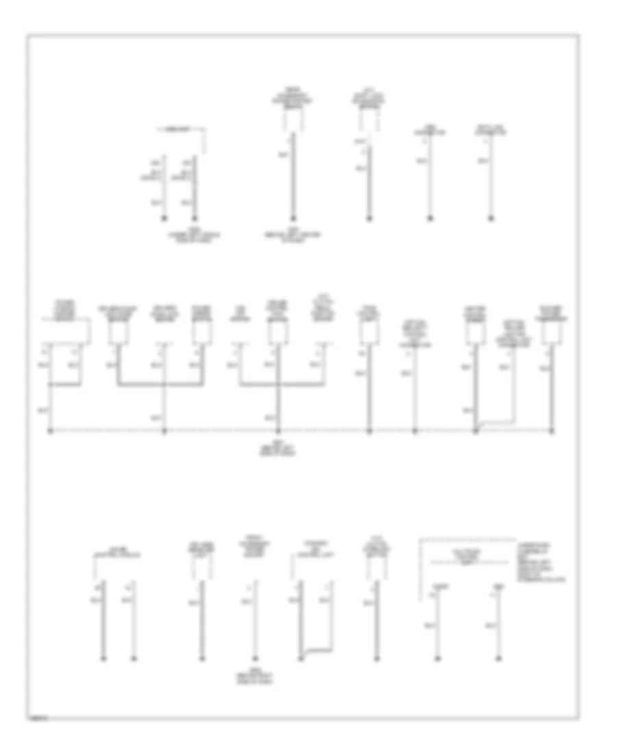
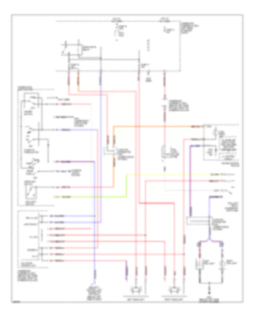
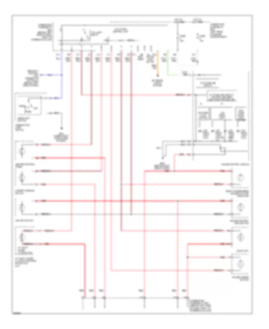
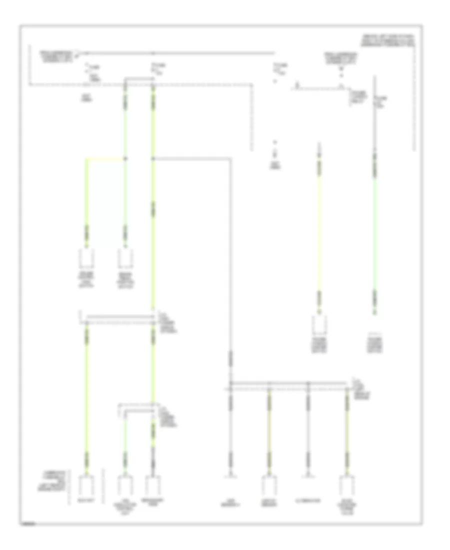
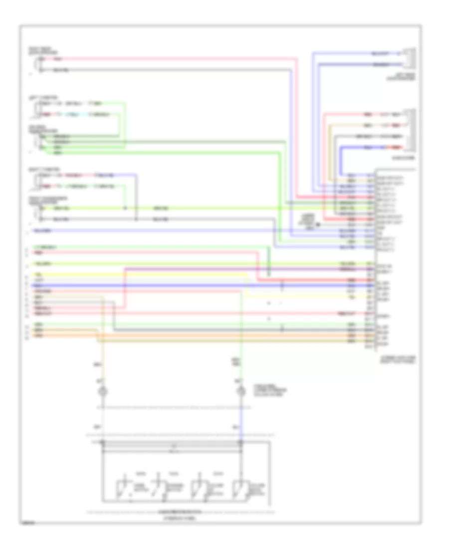
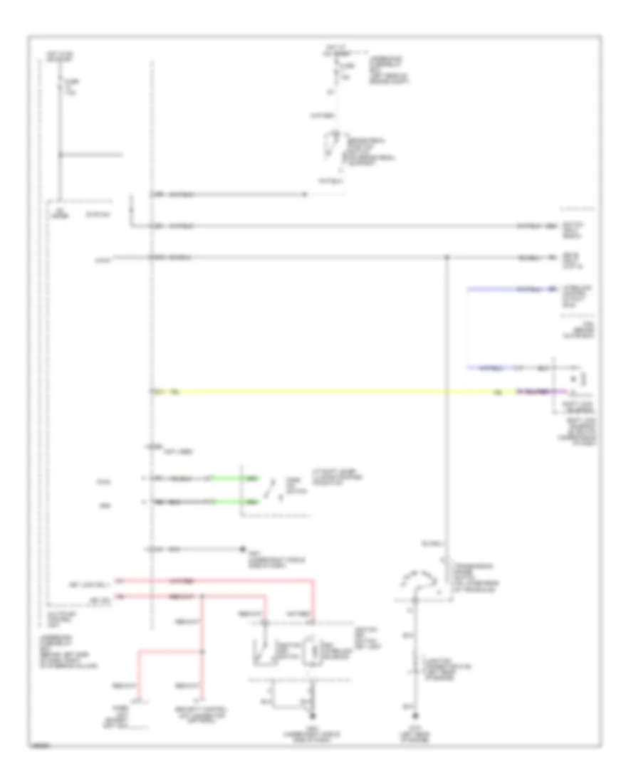
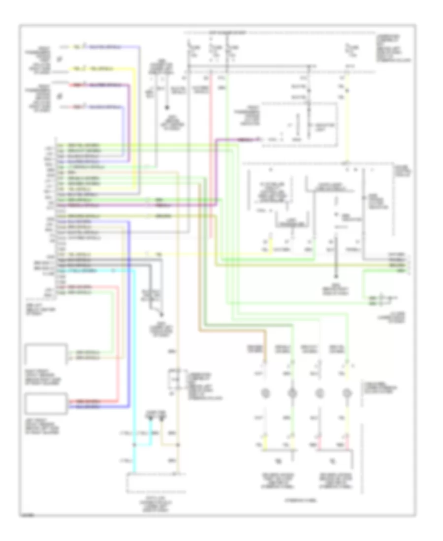
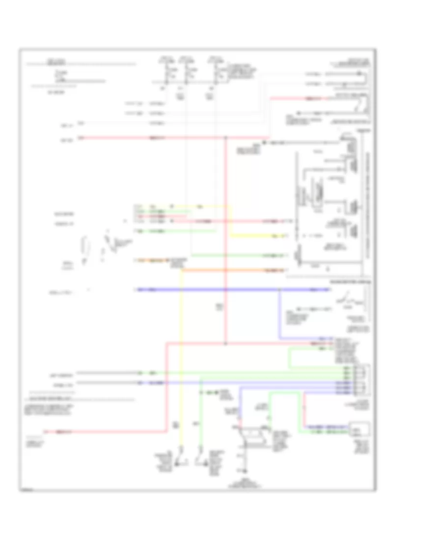
AIR CONDITIONING
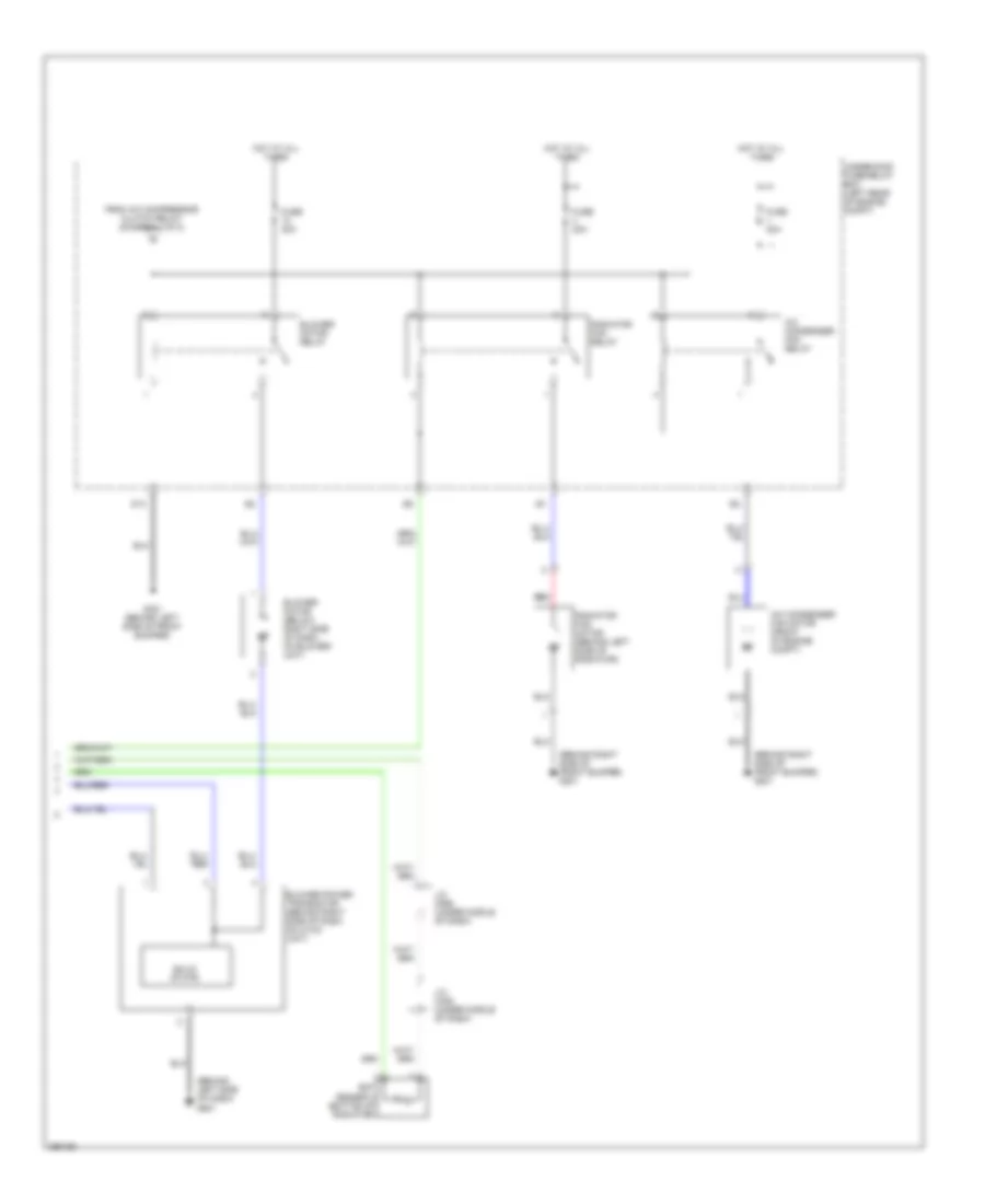
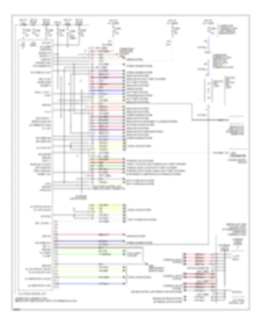
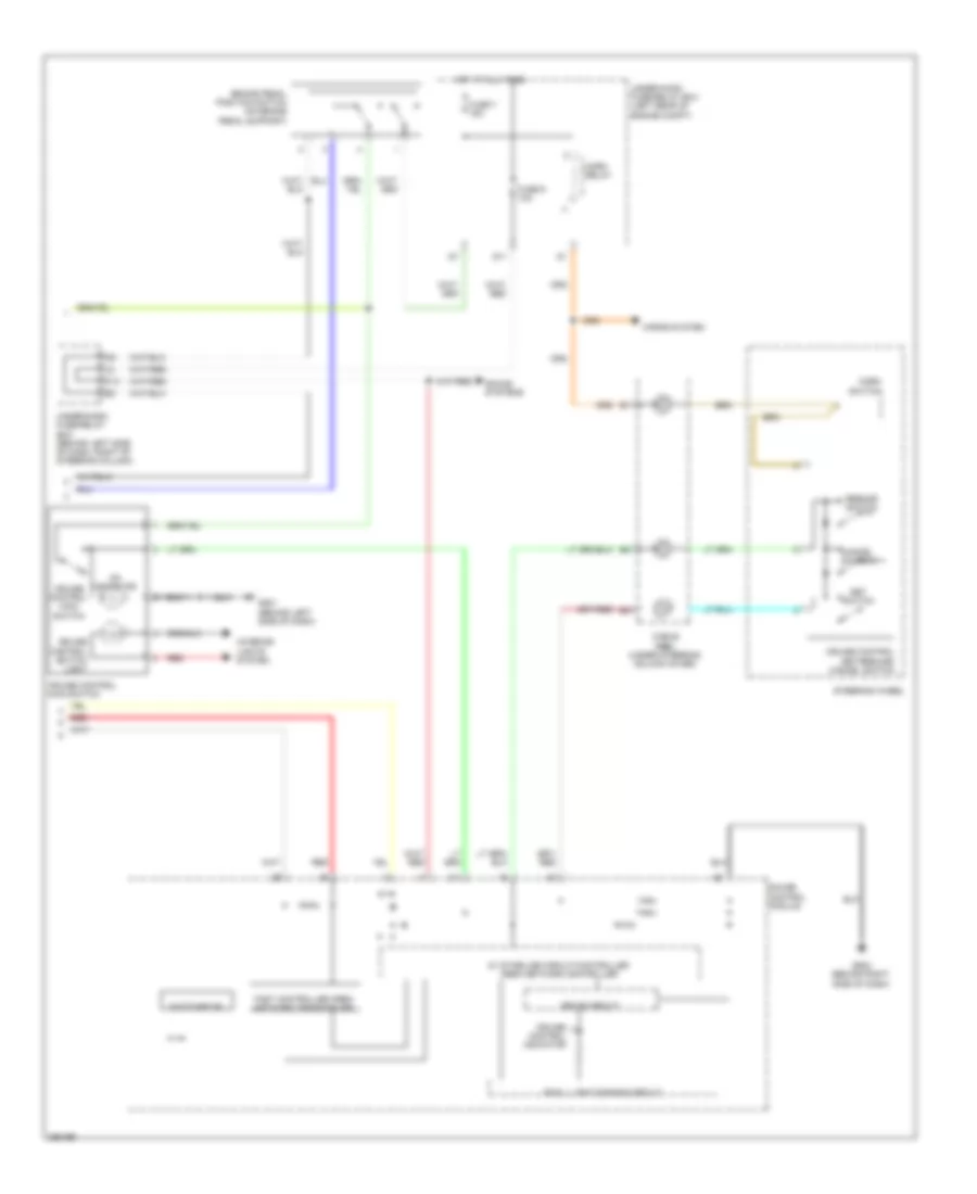
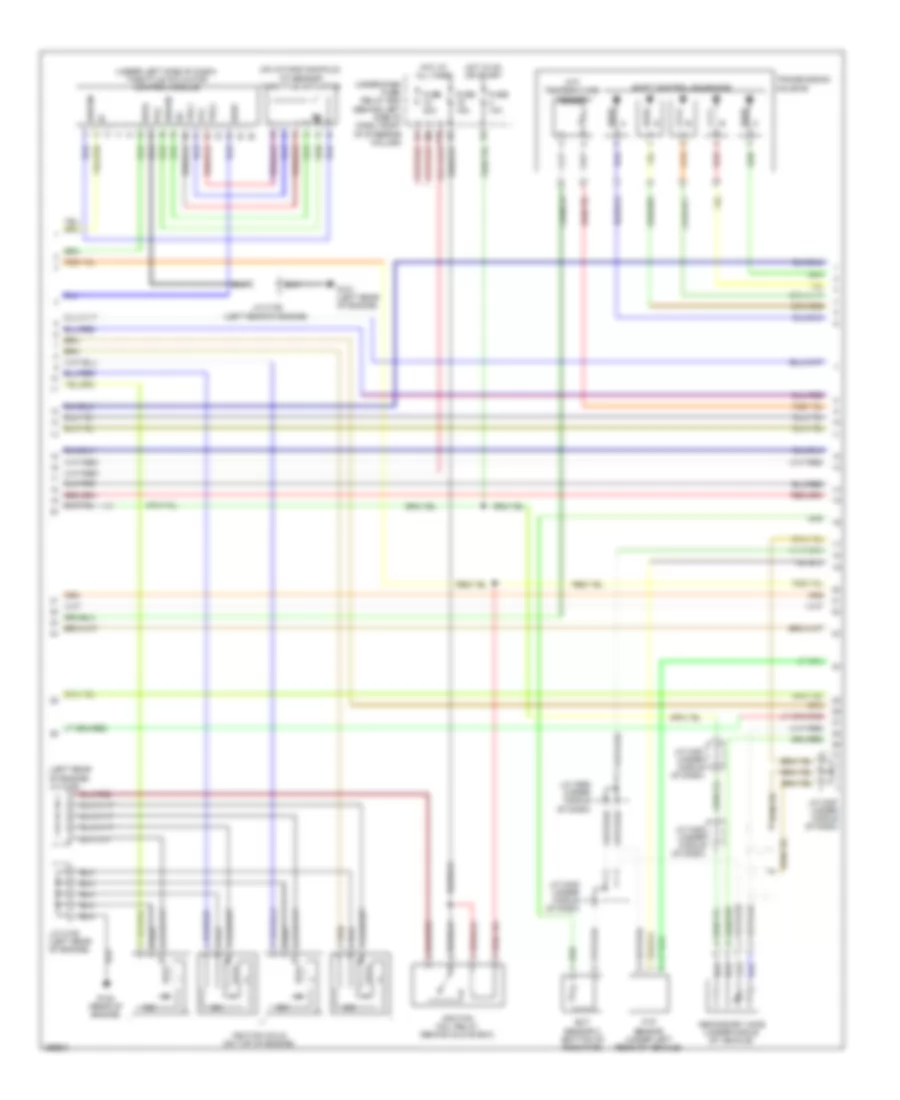
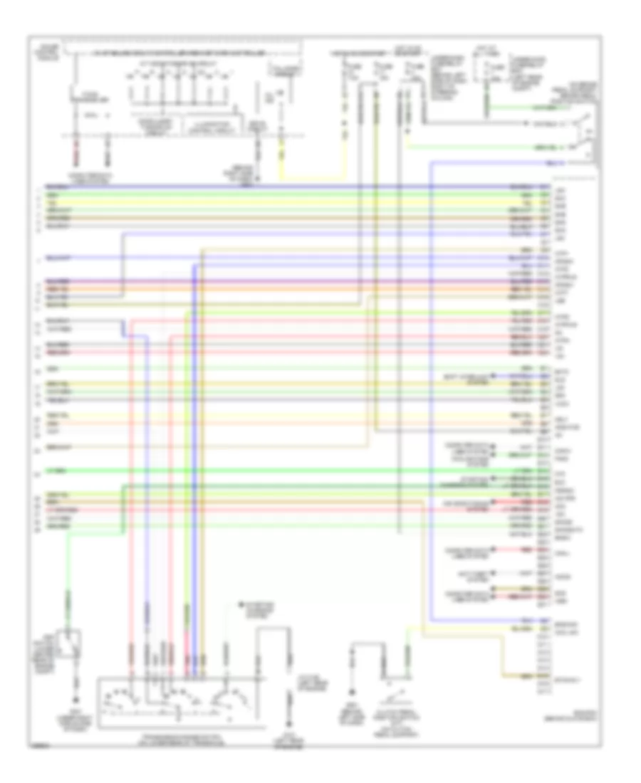
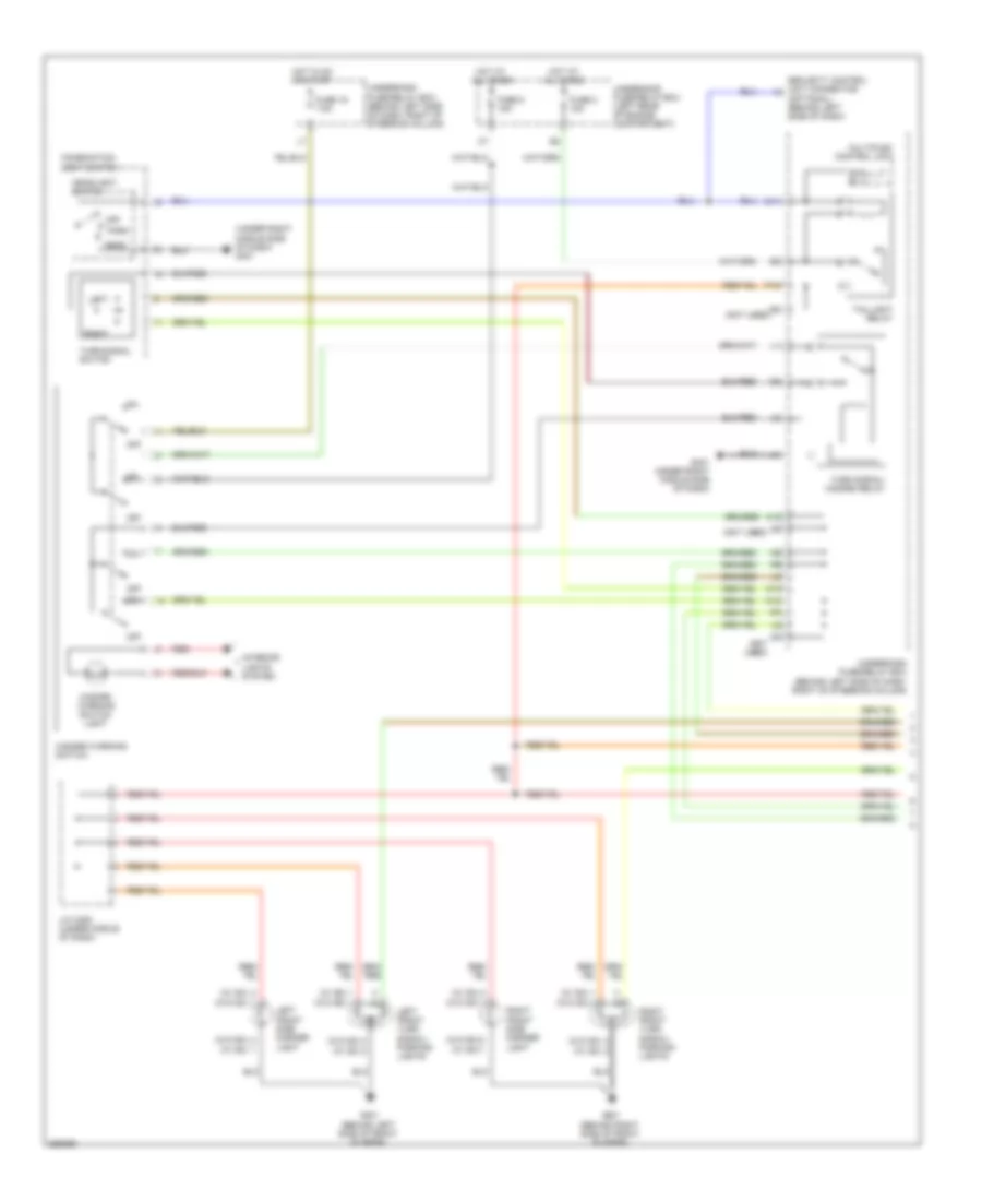
Manual A/C Wiring Diagram (1 of 2) for Honda Element LX 2007
 https://portal-diagnostov.com/license.html
Automotive Electricians Portal FZCO
Automotive Electricians Portal FZCO
https://portal-diagnostov.com/license.html
https://portal-diagnostov.com/license.html
Automotive Electricians Portal FZCO
Automotive Electricians Portal FZCO
List of elements for Manual A/C Wiring Diagram (1 of 2) for Honda Element LX 2007:
- (behind glove box) ecm/pcm
- (behind left side of dash) g501
- 5v stabilize circuit/ controller area network controller
- A/c compressor
- A/c compressor clutch
- A/c compressor clutch relay
- A/c press sw
- A/c pressure switch (right front of engine compt)
- Air mix control motor (below left side of dash, on hvac unit)
- Air mix cool
- Air mix hot
- Air mix potential
- Amd- p
- Blower feedback
- Blower pwr trans
- Bus meter
- Computer data lines system
- D10
- Defogger system
- E11
- E12
- E18
- E24
- Evap sensor
- Evaporator temperature sensor (behind left side of dash, near hvac unit)
- F-can (high)
- F-can (low)
- F-can transceiver
- Fan control
- Fresh
- Frs
- Fuse 10a
- Fuse 30a
- Gauge control module
- Ground
- Heater control panel
- High
- Hot at all times
- Hot in on
- Htr panel light
- Ig2
- Ig2 power
- Interior lights system
- K10
- Low
- M- cool
- M- def
- M- hot
- M- vent
- Mode
- Mode 1
- Mode 2
- Mode 3
- Mode 4
- Mode control motor (behind right side of dash, on hvac unit)
- Mode def
- Mode vent
- Multiplex control unit
- Rear defog
- Rec
- Recirculate
- Recirculation control motor (behind right side of dash, on blower unit)
- Red
- Relay ctrl
- S- com
- S5v
- Sensor ground
- Sensor input
- To blower motor relay (diagram 2 of 2)
- Uart transceiver
- Underdash fuse/relay box (behind left side of dash, right of steering column)
- Underhood fuse/relay box (left rear of engine compt)
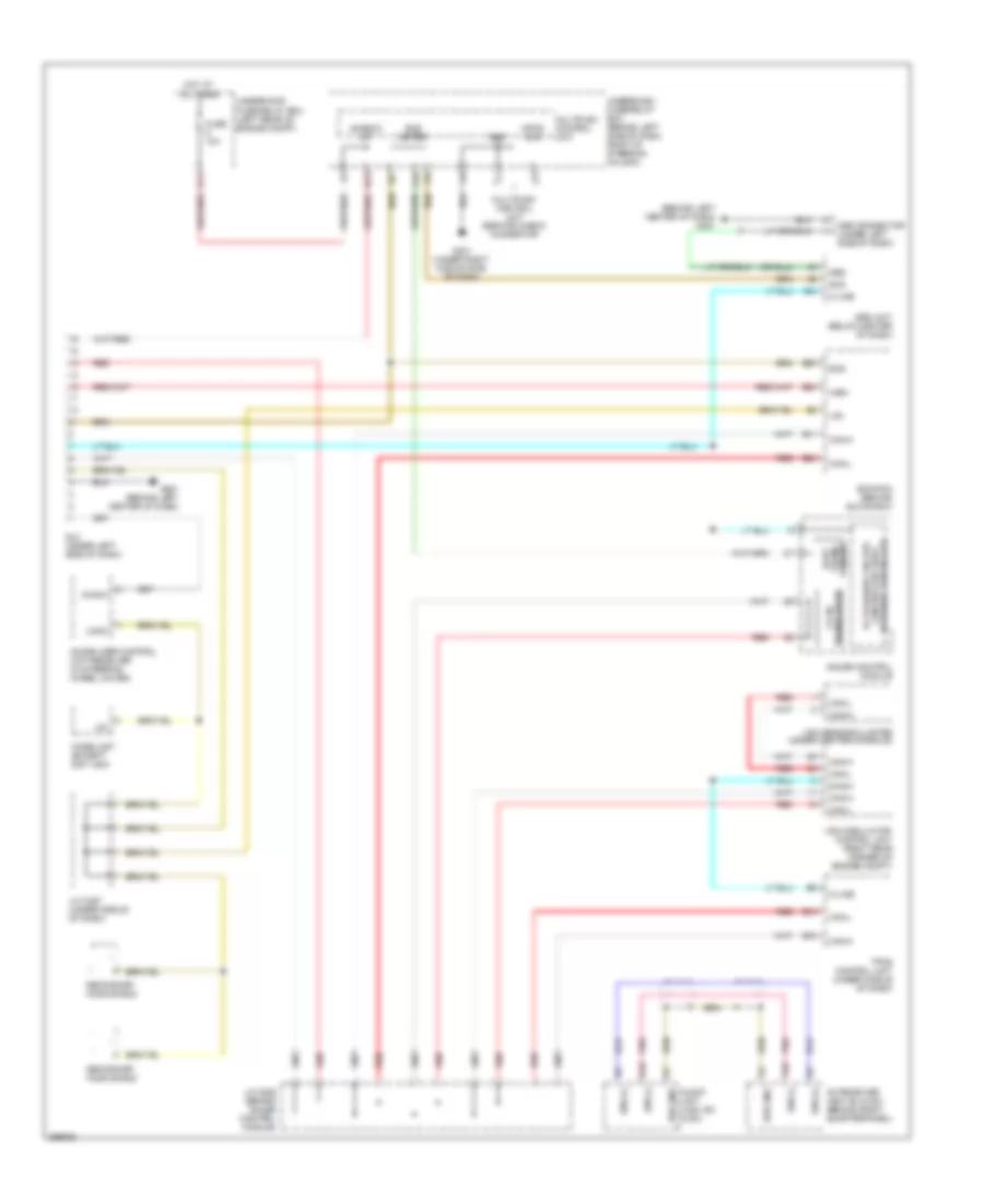
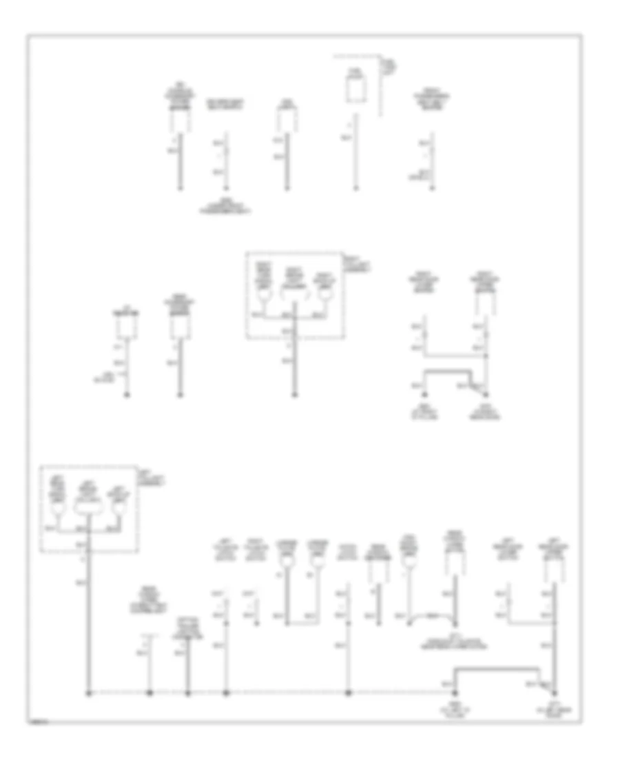
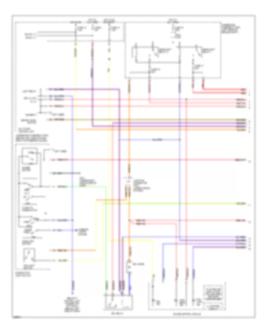
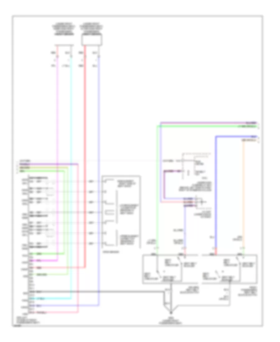
Manual A/C Wiring Diagram (2 of 2) for Honda Element LX 2007
List of elements for Manual A/C Wiring Diagram (2 of 2) for Honda Element LX 2007:
- (behind left side of dash) g501
- (behind right side of front bumper) g201
- A/c condenser fan motor (front of engine compt)
- A/c condenser fan relay
- Blower motor (below right side of dash, on blower unit)
- Blower motor relay
- Blower power transistor (behind right side of dash, on hvac unit)
- D13
- Ect sensor 2 (bottom of radiator)
- From a/c compressor clutch relay (diagram 1 of 2)
- Fuse 20a
- Fuse 30a
- Fuse 40a
- G301 (behind left side of front bumper)
- Hot at all times
- J/c c405 (under middle of dash)
- J/c c559 (under middle of dash)
- Radiator fan motor (behind left side of radiator)
- Radiator fan relay
- Red
- Solid state
- Underhood fuse/relay box (left rear of engine compt)
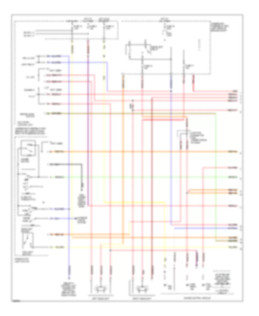
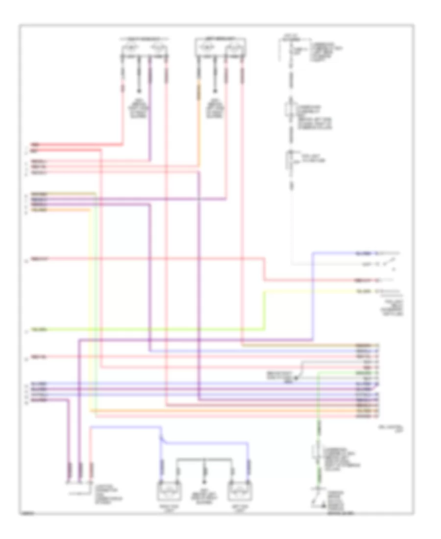
ANTI-LOCK BRAKES
Anti-lock Brakes Wiring Diagram for Honda Element LX 2007
List of elements for Anti-lock Brakes Wiring Diagram for Honda Element LX 2007:
- +b p
- +b v
- 5v stabilize circuit/controller area network controller
- Abs ind
- Brake fluid level switch (on brake fluid reservoir)
- Brake pedal position switch (on brake pedal support)
- Brake system ind
- Can h
- Can l
- Canada
- Clst gnd
- Clst ig
- Compulsory turning-on circuit
- Computer data lines system
- Diag ii
- Drive circuit
- Drl control unit
- E11
- E22
- E24
- Ecm/pcm (behind glove box)
- F-can tranceiver
- Fail-safe circuit
- Fl b+
- Fl gnd
- Fr b+
- Fr gnd
- Fuse 10 30a
- Fuse 10 7.5a
- Fuse 18 30a
- Fuse 4 10a
- Fuse 7 15a
- G202 (behind right side of front bumper)
- G401 (under right middle side of dash)
- G501 (behind left side of dash)
- G502 (behind right side of dash)
- Gauge control module
- Gnd p
- Gnd v
- Hot at all times
- Hot in on or start
- Ig2
- Interior lights system
- Junction connector c405 (under middle of dash)
- Junction connector c457 (under middle of dash)
- K10
- Left front wheel speed sensor (left side of engine compt)
- Left rear wheel speed sensor (on left rear wheel)
- Multiplex control unit
- Parking brake switch (ex, lx: under center console) (sc: base of parking brake lever)
- Red
- Right front wheel speed sensor (right side of engine compt)
- Right rear wheel speed sensor (on right rear wheel)
- Rl b+
- Rl gnd
- Rr b+
- Rr gnd
- S gnd
- Steering angle sensor (on steering column)
- Stra
- Strb
- Strz
- Svcc
- Uart tranceiver
- Under- dash fuse/ relay box (behind left side of dash, right of steering column)
- Underdash fuse/relay box (behind left side of dash, right of steering column)
- Underhood fuse/relay box (left rear of engine compt)
- Usa
- Vsa activation ind
- Vsa ind
- Vsa modulator- control unit (right rear corner of engine compt)
- Vsa off switch
- Vsa sensor cluster (under center console)
- Warning drive circuit
ANTI-THEFT
Forced Entry Wiring Diagram, Accessory for Honda Element LX 2007
List of elements for Forced Entry Wiring Diagram, Accessory for Honda Element LX 2007:
- (not used)
- Back up (b+)
- C11
- Combination light switch
- D11
- Door locks system
- Driver's door switch (front of left rear door)
- Drl h/l sw
- Front passenger's door switch (front right rear door)
- Fuse 10a
- Fuse 15a
- Fuse 7.5a
- G401 (under right middle side of dash)
- G501 (behind left side of dash)
- G553 (at left "d" pillar)
- Hatch latch switch (middle of hatch)
- Horn (behind left side of front bumper)
- Horn relay
- Horn sw
- Horns system
- Hot at all times
- Hot in on or start
- Ig1 meter
- Ignition key switch
- Ignition key switch/key light
- Immobilizer circuit
- Interior lights system
- Junction connector c457 (under middle of dash)
- K/l set
- K/l unset
- Key sw
- Keyless receiver unit (under left side of dash)
- Left door sw
- Left tailgate latch switch (left side of tailgate)
- Microphone
- Multiplex control unit
- Nca
- P18
- Red
- Right door sw
- Right tailgate latch switch (right side of tailgate)
- Security control unit (behind left side of dash)
- Security led
- Small lt rly
- Trunk sw
- Underdash fuse/relay box (behind left side of dash, right of steering column)
- Underhood fuse/relay box (left rear of engine compartment)
Immobilizer Wiring Diagram for Honda Element LX 2007
List of elements for Immobilizer Wiring Diagram for Honda Element LX 2007:
- (behind
- Alarm
- Brake lever)
- Connector (optional)
- D11
- D12
- Data link connector (dlc) (under left side of dash)
- Diag-h
- E17
- E27
- Ecm/pcm (behind glove box)
- Fuel pump
- Fuel tank unit (in fuel tank)
- Fuse 10a
- Fuse 15a
- G101 (left rear of engine)
- G401 (under right middle side of dash)
- G552 (under front passenger's seat)
- Gauge control module
- Gnd
- H/brake
- Hot at all times
- Hot in on or start
- Ig1
- Ignition key switch
- Ignition key switch/key
- Igp1
- Igp2
- Immo cd
- Immobi- lizer code
- Immobilizer control unit receiver (in steering wheel cover)
- Immobilizer system indicator
- Imocd
- Imoes unit (except 2007 usa)
- Imofpr
- Junction connector c105 (left rear of engine)
- Junction connector c106 (left rear of engine)
- Junction connector c107 (behind glove box)
- Junction connector c457 (under middle of dash)
- K12
- Key out
- Key sw
- Left side of dash)
- Lg1
- Lg2
- Lg3
- Mrly
- Multiplex control unit
- Parking brake switch (ex, lx: under center console) (sc: base of parking
- Pg1
- Pg2
- Pgm-fi main relay 1 (behind glove box)
- Pgm-fi main relay 2 (behind glove box)
- Security control
- Snet
- Underdash fuse/relay box (behind left side of dash, right of steering column)
- Underhood fuse/relay box (left rear of engine compt)
- Unit
BODY CONTROL MODULES
Body Control Modules Wiring Diagram for Honda Element LX 2007
List of elements for Body Control Modules Wiring Diagram for Honda Element LX 2007:
- (behind left side of dash, right of steering column) under-dash fuse/relay box
- (not used)
- (under right middle side of dash) g401
- +b back up
- +b day lt
- +b door lock
- +b rr fog
- A/c press sw (acs)
- Acc radio
- Air conditioning system
- Anti-theft system
- Atp-p
- Brake fluid level switch (on brake fluid reservoir)
- Brake level sw
- Bus meter
- C11
- Cruise control & exterior lights systems
- D/l dr mtr (unlck)
- D/l mtr (lck)
- D/l mtr (unlck)
- D/l remote sw (lck)
- D/l remote sw (unlck)
- D/l sil-con sw (lck)
- D/l sil-con sw (unlck)
- D10
- D11
- D14
- Dimmer hi
- Door locks system
- Dr belt sw
- Drl h/l sw
- Engine controls system
- Exterior lights system
- F10
- F11
- F12
- Fr washer mtr
- Fr wiper (as)
- Fr wiper (int)
- Fr wiper int unit
- Fuse (not used)
- Fuse 10a
- Fuse 15a
- Fuse 20a
- Fuse 7.5a
- G502 (behind right side of dash)
- Gauge control module
- Ground
- H/l hi
- H/l low
- Headlights & anti-theft systems
- Headlights & instrument cluster systems
- Headlights & warning systems
- Headlights system
- Horn sw
- Horns system
- Hot at all times
- Hot in on
- Hot in on or acc
- Hot in on or start
- Ig1 mtr
- Ig1 wiper
- Ig2 day lt
- Ignition key light
- Ignition key switch/ key light
- Illum +
- Immobi code
- Interior lights system
- Interior lights, door locks & anti-theft systems
- Intr lt-
- K/l set
- K/l unset
- K10
- K11
- K16
- Key lck sol +
- Key lt-
- Key sw
- Keyless com
- L10
- Left door sw
- Lighting rly -
- Mpcs chk
- Multiplex control unit
- Multiplex control unit service check connector
- Option connector
- P-pin
- P11
- P15
- P16
- P17
- P18
- Red
- Right door sw
- Shift interlock system
- Small
- Small lt rly -
- Stop sw
- Transmissions system
- Trunk sw (t/g sw)
- Trunk, tailgate, fuel doors & anti-theft systems
- Uart transceiver
- Under-dash fuse/relay box (behind left side of dash, right of steering column)
- Under-hood fuse/relay box (left rear of engine compt)
- Warning system
- Warning, door locks & anti-theft systems
- Wiper/washer system
- Y10
- Y11
- Y12
- Y13
COMPUTER DATA LINES
Computer Data Lines Wiring Diagram for Honda Element LX 2007
List of elements for Computer Data Lines Wiring Diagram for Honda Element LX 2007:
- (behind left center of dash) g451
- +b back up
- 5v stabilize circuit/ controller area network controller
- A10
- A24
- Audio unit (usa: ex & sc)
- B10
- B19
- Bus (+)
- Bus (-)
- Bus gnd
- Bus meter
- Can-h
- Can-l
- Ceiver trans- uart
- D10
- D11
- Diag-h
- Diag-ii
- Dlc (under left side of dash)
- E11
- E12
- E24
- E29
- E30
- Ecm/pcm (behind glove box)
- Fuse 10a
- G401 (under right middle side of dash)
- G451 (behind left center of dash)
- Gauge control module
- Gnd
- Hot at all times
- Immobilizer control unit-receiver (in steering wheel cover)
- Imoes unit (except 2007 usa)
- J/c c406 (behind gauge control module)
- J/c c457 (under middle of dash)
- K-line
- K10
- Lg1
- Lg3
- Logic
- Mes
- Mes connector (under left side of dash)
- Mpcs chk
- Multiplex control unit
- Multiplex control unit service check connector
- Pnk
- Red
- Scs
- Secondary ho2s shield
- Srs unit (below center of dash)
- Tpms control unit (under middle of dash)
- Transceiver f-can
- Underdash fuse/relay box (behind left side of dash, right of steering column)
- Underhood fuse/relay box (left rear of engine compt)
- Vsa modulator- control unit (right rear corner of engine compt)
- Vsa sensor cluster (under center console)
- Wen
- Xm receiver (usa: ex & sc) (behind right quarterpanel)
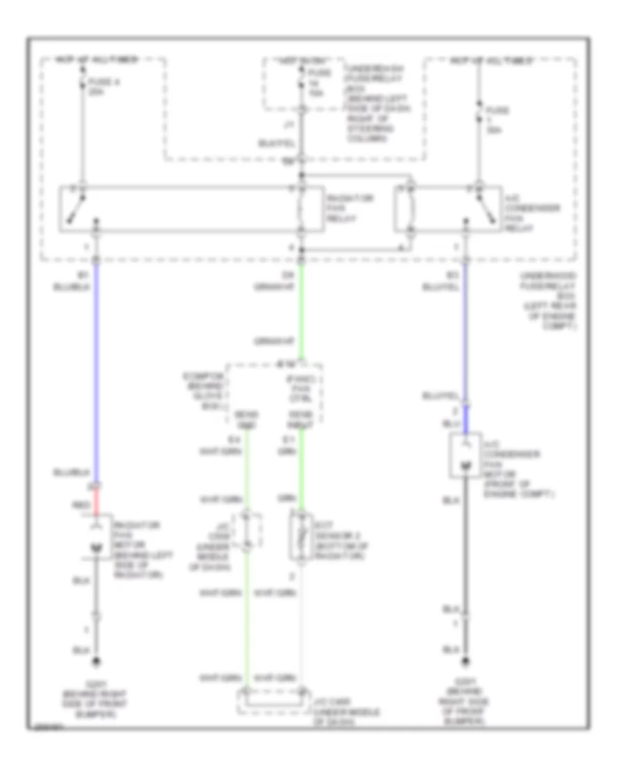
COOLING FAN
Cooling Fan Wiring Diagram for Honda Element LX 2007
List of elements for Cooling Fan Wiring Diagram for Honda Element LX 2007:
- (fanc) fan ctrl
- A/c condenser fan motor (front of engine compt)
- A/c condenser fan relay
- E12
- Ecm/pcm (behind glove box)
- Ect sensor 2 (bottom of radiator)
- Fuse 10a
- Fuse 30a
- Fuse 4 20a
- G201 (behind right side of front bumper)
- Hot at all times
- Hot in on
- J/c c405 (under middle of dash)
- J/c c559 (under middle of dash)
- Radiator fan motor (behind left side of radiator)
- Radiator fan relay
- Red
- Sens gnd
- Sens input
- Underdash fuse/relay box (behind left side of dash, right of steering column)
- Underhood fuse/relay box (left rear of engine compt)
CRUISE CONTROL
Cruise Control Wiring Diagram (1 of 2) for Honda Element LX 2007
List of elements for Cruise Control Wiring Diagram (1 of 2) for Honda Element LX 2007:
- A/t
- A20
- A21
- A23
- A24
- A25
- A26
- App sensor (right rear corner of engine compt)
- B19
- B20
- C10
- C18
- Can h
- Can l
- Clutch pedal position switch (m/t) (on clutch pedal support)
- D15
- Dbw m+
- Dbw m-
- E11
- E22
- E24
- Ecm/pcm (behind glove box)
- Engine controls system
- Fuse 10 7.5a
- Fuse 4 10a
- Fuse 6 15a
- Fuse 8 15a
- G101 (left rear of engine)
- G501 (behind left side of dash)
- Hot at all times
- Hot in on or start
- Junction connector c105 (left rear of engine)
- Junction connector c106 (left rear of engine)
- Junction connector c107 (behind glove box)
- Junction connector c406 (behind gauge control module)
- M/t
- Pg2
- Pgm-fi main relay 1 (behind glove box)
- Red
- Ref vol
- Relay ctrl
- Sedf
- Sefd
- Sens gnd
- Sens input
- Sw input
- Thl1
- Thl2
- Throttle actuator control module (under left side of dash)
- Throttle actuator control module relay (behind glove box)
- Tp sensor/ throttle actuator (on intake manifold)
- Transmission range switch (a/t) (on lower rear of transaxle)
- Under-dash fuse/relay box (behind left side of dash, right of steering column)
- Under-hood fuse/relay box (left rear of engine compt)
- Vcc
Cruise Control Wiring Diagram (2 of 2) for Honda Element LX 2007
List of elements for Cruise Control Wiring Diagram (2 of 2) for Honda Element LX 2007:
- 5v stabilize circuit/controller area network controller
- Brake pedal position switch (on brake pedal support)
- Cable reel (under steering column cover)
- Cancel switch
- Cruise control indicator
- Cruise control main switch
- Cruise control set/resume/ cancel switch
- Cruise control switch light
- D11
- Drive circuit
- Fast controller area network transceiver
- Fuse 7 15a
- Fuse 9 10a
- G501 (behind left side of dash)
- G502 (behind right side of dash)
- Gauge control module
- Horn relay
- Horn switch
- Horns system
- Hot at all times
- Interior lights system
- K13
- On indicator
- Red
- Resume switch
- Set switch
- Small light dimming circuit
- Sound systems
- Steering wheel
- Switched b+
- Under-dash fuse/relay box (behind left side of dash, right of steering column)
- Under-hood fuse/relay box (left rear of engine compt)
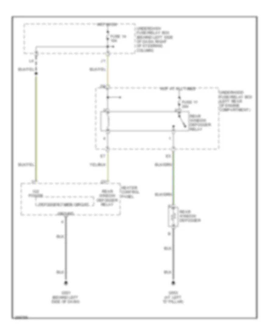
DEFOGGERS
Defoggers Wiring Diagram for Honda Element LX 2007
List of elements for Defoggers Wiring Diagram for Honda Element LX 2007:
- Defogger timer circuit
- Fuse 11 20a
- Fuse 14 10a
- G501 (behind left side of dash)
- G553 (at left "d" pillar)
- Ground
- Heater control panel
- Hot at all times
- Hot in on
- Ig2 power
- Rear window defogger
- Rear window defogger relay
- Underdash fuse/relay box (behind left side of dash, right of steering column)
- Underhood fuse/relay box (left rear of engine compartment)
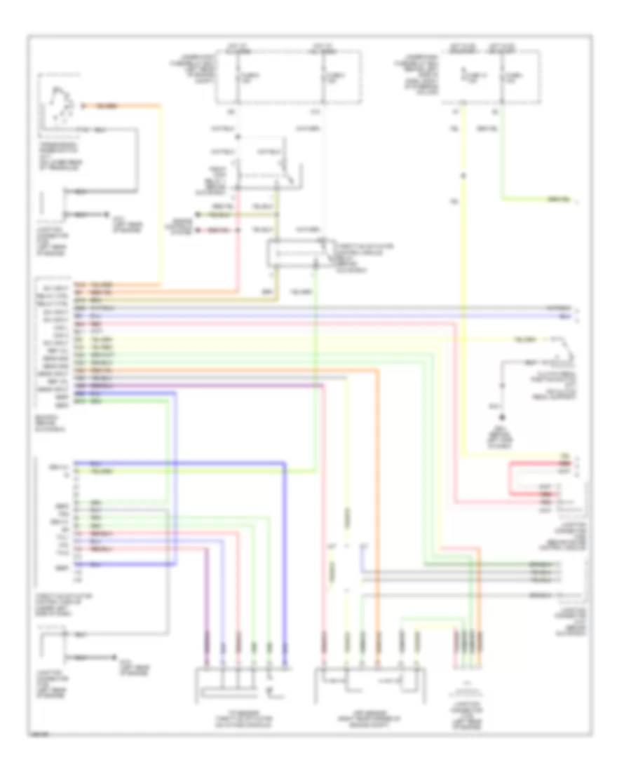
ENGINE PERFORMANCE
2.4L
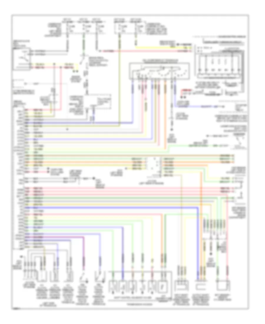
2.4L, Engine Performance Wiring Diagram (1 of 4) for Honda Element LX 2007
List of elements for 2.4L, Engine Performance Wiring Diagram (1 of 4) for Honda Element LX 2007:
- (behind glove box) j/c c107
- (behind glove box) pgm-fi main relay 1
- (behind glove box) pgm-fi main relay 2
- (behind glove box) throttle actuator control module relay
- (in fuel tank) fuel tank unit
- (left rear of engine)
- (left rear of engine) g101
- (left rear of engine) j/c c105
- A10
- A11
- A12
- A13
- A14
- A15
- A16
- A17
- A18
- A19
- A20
- A21
- A22
- A23
- A24
- A25
- A26
- A27
- A28
- A29
- A30
- A31
- Afs (+)
- Afs (-)
- Afshtc
- Altc
- Altf
- Altl
- Apsa
- Apsb
- Atpp
- Atpr
- B10
- B11
- B12
- B13
- B14
- B15
- B16
- B17
- B18
- B19
- B20
- B21
- B22
- B23
- B24
- C10
- Ckp
- Ckp sensor (lower right front of engine, near crankshaft pulley)
- Cmp sensor b (rear of cylinder head)
- Cmpa
- Cmpb
- D3sw
- Ecm/pcm (behind glove box)
- Ect 1
- Evap canister purge valve (at right rear of engine)
- Exterior lights system
- Fuel injectors (left side of engine)
- Fuel pump
- Fuse 15a
- G101 (left rear of engine)
- G552 (under front passenger's seat)
- Hot at all times
- Iat
- Igp1
- Igp2
- Igpls1
- Igpls2
- Igpls3
- Igpls4
- Inj1
- Inj2
- Inj3
- Inj4
- J/c c105
- J/c c105 (left rear of engine)
- J/c c106 (left rear of engine)
- J/c c107
- Lg1
- Lg2
- Map
- Pcs
- Pg1
- Pg2
- Red
- Rocker arm oil control solenoid (vtec solenoid valve) (on right front of cylinder head)
- Rocker arm oil pressure switch (vtec oil pressure switch) (on right front of cylinder head)
- Sedf
- Sefd
- Sg1
- Sg2
- Starting/ charging system
- Under- hood fuse/relay box (left rear of engine compt)
- Vcc1
- Vcc2
- Vtc
- Vtc oil control solenoid valve (on front of cylinder head)
- Vtpsw
- Vts
2.4L, Engine Performance Wiring Diagram (2 of 4) for Honda Element LX 2007
List of elements for 2.4L, Engine Performance Wiring Diagram (2 of 4) for Honda Element LX 2007:
- (behind glove box) j/c c107
- (behind left center of dash) g451
- (left rear of engine) g101
- (left rear of engine) j/c c105
- (rear of cylinder head) cmp sensor a
- (right rear of transaxle) (a/t) input shaft (mainshaft) speed sensor
- (under middle of dash) shift lock solenoid/ d3 switch
- 2nd clutch transmission fluid pressure switch (top of transaxle)
- 3rd clutch transmission fluid pressure switch (rear of transaxle)
- A/f sensor (on front of three-way catalytic converter)
- A/f sensor relay (behind glove box)
- A/t clutch pressure solenoid valves control (a: top of transaxle) (b & c: left side of transaxle)
- App sensor (right rear corner of engine compt)
- D3 switch
- Ect sensor 1 (rear of cylinder head)
- Evap canister vent shut valve (under left rear of vehicle)
- G101 (left rear of engine)
- Iat sensor
- J/c c105 (left rear of engine)
- J/c c106 (left rear of engine)
- J/c c107 (behind glove box)
- Knock sensor (left side of engine)
- Maf/iat sensor (left side of intake manifold)
- Map sensor
- Map sensor (left side of intake manifold)
- Output shaft (countershaft) speed sensor (a/t: right front of transaxle) (m/t: top of transaxle)
- Red
2.4L, Engine Performance Wiring Diagram (3 of 4) for Honda Element LX 2007
List of elements for 2.4L, Engine Performance Wiring Diagram (3 of 4) for Honda Element LX 2007:
- (left rear of engine) j/c c106
- (on intake manifold) tp sensor/ throttle actuator
- (under left side of dash) throttle actuator control module
- Atf temperature sensor
- Dbw m+
- Dbw m-
- Ect sensor 2 (bottom of radiator)
- Ftp sensor (under left rear of vehicle)
- Fuse 10a
- Fuse 15a
- Fuse 20a
- G101 (left rear of engine)
- G102 (rear of engine)
- Hot at all times
- Hot in on or start
- Icm
- Ignition coil relay (behind glove box)
- Ignition coils (on top of engine)
- J/c c105 (left rear of engine)
- J/c c106 (left rear of engine)
- J/c c405 (under middle of dash)
- J/c c457 (under middle of dash)
- J/c c559 (under middle of dash)
- P10
- Pg2
- Red
- Secondary ho2s (under middle of vehicle)
- Sedf
- Sefd
- Shift control solenoids
- Thl1
- Thl2
- Transmission housing
- Under-dash fuse/ relay box (behind left side of dash, right of steering column)
- Vcc
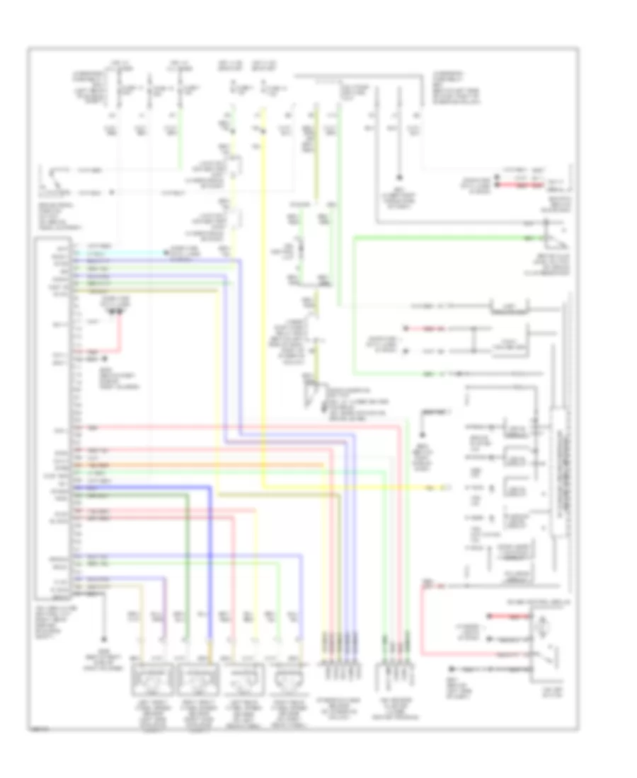
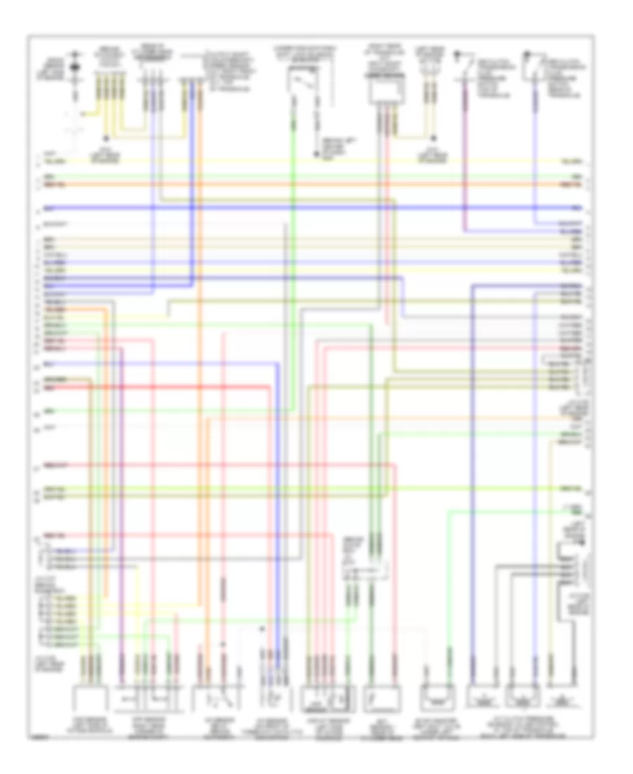
2.4L, Engine Performance Wiring Diagram (4 of 4) for Honda Element LX 2007
List of elements for 2.4L, Engine Performance Wiring Diagram (4 of 4) for Honda Element LX 2007:
- (behind right side of dash) g502
- (on brake pedal support) brake pedal position switch
- 5v stabilize circuit/controller area network controller
- A/t indicator drive circuit
- Acc
- Afshtcr
- Air conditioning system
- Anti-theft system
- Atft
- Atp1
- Atp2
- Atpd
- Atpfwd
- Atpn
- Atprvs
- Bksw
- Bkswnc
- C10
- C11
- C12
- C13
- C14
- C15
- C16
- C17
- C18
- C19
- C20
- C21
- C22
- Can-h
- Can-l
- Cccl sw
- Clutch pedal position switch (m/t) (on clutch pedal support)
- Compulsory turning on circuit
- Computer data lines system
- Cooling fans system
- D10
- D11
- D12
- D13
- D14
- D15
- D16
- D17
- Drive circuit
- E10
- E11
- E12
- E13
- E14
- E15
- E16
- E17
- E18
- E19
- E20
- E21
- E22
- E23
- E24
- E25
- E26
- E27
- E28
- E29
- E30
- E31
- Ecm/pcm (behind glove box)
- Ect2
- Eld
- Etcs rly
- F-can transceiver
- Fail-safe circuit
- Fanc
- Ftp
- Fuse 10a
- Fuse 15a
- Fuse 7.5a
- G101 (left rear of engine)
- G401 (under right middle side of dash)
- G501 (behind left side of dash)
- Gauge control module
- Hot at all times
- Hot in on or start
- Ig1
- Illumination control circuit
- Imo fpr
- Imocd
- J/c c106 (left rear of engine)
- Lg3
- Lsa
- Lsb
- Lsc
- Mil ind
- Mrly
- Op2sw
- Op3sw
- Pnk
- Psp switch (lower center rear of engine compt)
- Pspsw
- Red
- Scs
- Sg3
- Sha
- Shb
- Shc
- Shd
- She
- Shift interlock system
- Sho2s
- Sho2shtc
- Sls
- Starting/ charging system
- Transmission range switch (on lower rear of transaxle)
- Under-dash fuse/relay box (behind left side of dash, right of steering column)
- Under-hood fuse/relay box (left rear of engine compt)
- Vcc3
- Vg+
- Vg-
- Vsv
- Wen
EXTERIOR LIGHTS
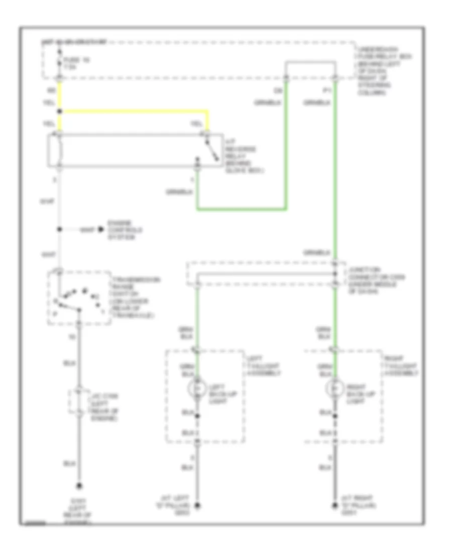
Back-up Lamps Wiring Diagram, A/T for Honda Element LX 2007
List of elements for Back-up Lamps Wiring Diagram, A/T for Honda Element LX 2007:
- (at left "d" pillar) g553
- (at right "d" pillar) g551
- A/t reverse relay (behind glove box)
- Engine controls system
- Fuse 10 7.5a
- G101 (left rear of engine)
- Hot in on or start
- J/c c106 (left rear of engine)
- Junction connector c559 (under middle of dash)
- Left back-up light
- Left taillight assembly
- Right back-up light
- Right taillight assembly
- Transmission range switch (on lower rear of transaxle)
- Underdash fuse/relay box (behind left of dash, right of steering column)
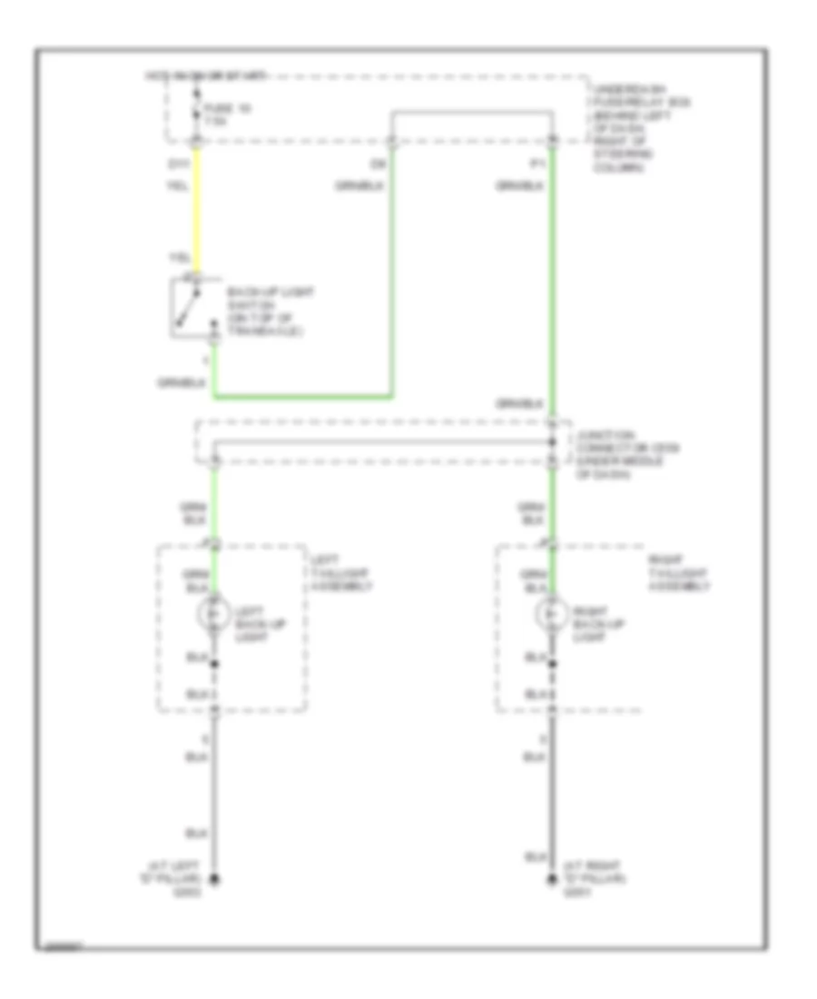
Back-up Lamps Wiring Diagram, M/T for Honda Element LX 2007
List of elements for Back-up Lamps Wiring Diagram, M/T for Honda Element LX 2007:
- (at left "d" pillar) g553
- (at right "d" pillar) g551
- Back-up light switch (on top of transaxle)
- D11
- Fuse 10 7.5a
- Hot in on or start
- Junction connector c559 (under middle of dash)
- Left back-up light
- Left taillight assembly
- Right back-up light
- Right taillight assembly
- Underdash fuse/relay box (behind left of dash, right of steering column)
Exterior Lamps Wiring Diagram (1 of 2) for Honda Element LX 2007
List of elements for Exterior Lamps Wiring Diagram (1 of 2) for Honda Element LX 2007:
- (not used)
- (optional) (behind left side of dash)
- (under right middle side of dash) g401
- (w/ sc)
- (w/o sc)
- C11
- C12
- C13
- Combination light switch
- Fuse 19 7.5a
- Fuse 2 15a
- Fuse 5 15a
- G201 (behind right side of front bumper)
- G301 (behind left side of front bumper)
- G401 (under right middle side of dash)
- Hazard warning switch
- Hazard warning switch light
- Head
- Headlight switch
- Hot at all times
- Hot in on or start
- Interior lights system
- J/c c405 (under middle of dash)
- Left
- Left front side marker light
- Left front turn signal/ parking lights
- M12
- Multiplex control unit
- Off
- P15
- Park
- Red
- Right
- Right front side marker light
- Right front turn signal/ parking lights
- Security control unit connector
- Small lt rly -
- Taillight relay
- Turn signal switch
- Turn signal/ hazard relay
- Underdash fuse/relay box (behind left side of dash, right of steering column)
- Underhood fuse/relay box (left rear of engine compartment)
Exterior Lamps Wiring Diagram (2 of 2) for Honda Element LX 2007
List of elements for Exterior Lamps Wiring Diagram (2 of 2) for Honda Element LX 2007:
- (behind left side of dash) g501
- (on brake pedal support)
- (under left side of dash) (optional) trailer lighting control unit
- +b trailer
- Back-up lamps circuit
- Brake pedal position switch
- Fuse 5 15a
- Fuse 7 15a
- G502 (behind right side of dash)
- G551 (at right "d" pillar)
- G553 (at left "d" pillar)
- Gauge control assembly
- Ground
- High mount brake light
- Hot at all times
- J/c c406 (behind gauge control module)
- J/c c559 (under middle of dash)
- L turn lt
- L turn/stop
- Left back-up light
- Left brake light/ taillight
- Left rear turn signal light
- Left taillight assembly
- Left turn signal indicator
- License plate light
- R turn lt
- R turn/stop
- Right back-up light
- Right brake light/ taillight
- Right rear turn signal light
- Right taillight assembly
- Right turn signal indicator
- Small
- Small lt
- Stop sw
- Trailer connector
- Trailer lighting connector (optional) (rear of cargo area)
- Underdash fuse/relay box (behind left side of dash, right of steering column)
- Underhood fuse/relay box (left rear of engine compartment)
GROUND DISTRIBUTION
Ground Distribution Wiring Diagram (1 of 4) for Honda Element LX 2007
List of elements for Ground Distribution Wiring Diagram (1 of 4) for Honda Element LX 2007:
- (a/t) mainshaft speed sensor
- A/t
- A/t clutch pressure control solenoid valve a
- A/t clutch pressure control solenoid valve b
- A/t clutch pressure control solenoid valve c
- A10
- A20
- Audio unit
- Battery
- Camshaft position (cmp) sensor a
- Camshaft position (cmp) sensor b
- Crankshaft position (ckp) sensor
- Engine
- G1 (left side of engine compt)
- G101 (left rear of engine)
- G102 (rear of engine)
- G2 (right side of engine compt)
- G202 (behind right side of front bumper)
- G503 (under middle of dash)
- Ignition coil 1
- Ignition coil 2
- Ignition coil 3
- Ignition coil 4
- Junction connector c105 (left rear of engine)
- Junction connector c106 (left rear of engine)
- Junction connector c107 (behind glove box)
- Knock sensor shield
- Output shaft (countershaft) speed sensor
- Powertrain control module (pcm)/ engine control module (ecm)
- Rocker arm oil control solenoid (vtec solenoid valve)
- Rocker arm oil pressure switch (vtec oil pressure switch)
- Stereo amplifier (ex & sc)
- Throttle actuator control module
- Transmission
- Transmission range switch
- Vsa modulator control unit
- Vtc oil control solenoid valve
Ground Distribution Wiring Diagram (2 of 4) for Honda Element LX 2007
List of elements for Ground Distribution Wiring Diagram (2 of 4) for Honda Element LX 2007:
- (a/t) a/t shift lever illumination/ park pin switch
- (canada) washer fluid level switch
- (lx & ex)
- (multiplex control unit service check connector)
- (not used)
- (sc)
- (sc) left headlight
- (sc) right headlight
- A/c condensor fan motor
- A/t
- Blower motor relay
- Brake fluid level switch
- Combination light switch
- D13
- Eld unit
- G201 (behind right side of front bumper)
- G301 (behind left side of front bumper)
- G401 (under right middle side of dash)
- Gnd
- Ignition key switch/key light
- K16
- Left front side marker light
- Left front turn signal/ parking lights
- Multiplex control unit
- Power steering pressure (psp) switch
- Power window relay
- Radiator fan motor
- Rear window washer motor
- Right front side marker light
- Right front turn signal/ parking lights
- Turn signal/ hazard relay
- Under-dash fuse/relay box (behind left side of dash, right of steering column)
- Under-hood fuse/relay box (left rear of engine compt)
- Windshield washer motor
- Windshield wiper motor
- Wiper/ washer switch
Ground Distribution Wiring Diagram (3 of 4) for Honda Element LX 2007
List of elements for Ground Distribution Wiring Diagram (3 of 4) for Honda Element LX 2007:
- (a/t) shift lock solenoid/d3 switch
- (canada) drl control unit
- (m/t) clutch interlock switch
- (m/t) clutch pedal position switch
- (option) security control unit connector
- (option) trailer lighting control unit connector
- A22
- A23
- Blower power transistor
- Cruise control main switch
- Data link connector
- Driver's door lock knob switch
- Driver's door lock switch
- Front accessory power socket
- G402 (under left middle side of dash)
- G451 (behind left center of dash)
- G501 (behind left side of dash)
- G502 (behind right side of dash)
- Gauge control module
- Gnd
- Heater control panel
- Keyless receiver unit
- Mes connector
- Multiplex control unit
- Power mirror switch
- Power window master switch
- Rear accessory power socket relay
- S-gnd
- Srs unit
- Tpms control unit
- Under-dash fuse/relay box (behind left side of dash, right of steering column)
- Vsa off switch
Ground Distribution Wiring Diagram (4 of 4) for Honda Element LX 2007
List of elements for Ground Distribution Wiring Diagram (4 of 4) for Honda Element LX 2007:
- (option) trailer lighting connector
- (sc) console accessory power socket
- A11
- D12
- Driver's seat belt switch
- Front passenger's seat belt switch
- Fuel pump
- Fuel tank unit
- G551 (at right "d" pillar)
- G552 (under front passenger's seat)
- G553 (at left "d" pillar)
- G711 (middle of tailgate, near rear wiper motor)
- G751 (in right rear door)
- G771 (in left rear door)
- Hatch latch switch
- High mount brake light
- Left back-up light
- Left brake light/ taillight
- Left rear door lower switch
- Left rear door upper switch
- Left rear turn signal light
- Left tailgate latch switch
- Left taillight assembly
- License plate light
- Ods unit
- Rear accessory power socket
- Rear window defogger
- Rear window wiper intermittent control unit
- Rear window wiper motor
- Right back-up light
- Right brake light/ taillight
- Right rear door lower switch
- Right rear door upper switch
- Right rear turn signal light
- Right tailgate latch switch
- Right taillight assembly
- Usa: ex & sc
- Xm receiver
HEADLIGHTS
Headlights Wiring Diagram, LX EX with DRL (1 of 2) for Honda Element LX 2007
List of elements for Headlights Wiring Diagram, LX EX with DRL (1 of 2) for Honda Element LX 2007:
- (not used)
- 5v stabilize circuit/con- troller area network controller
- B+ day lt
- Brake level switch
- Combination light switch
- Dimmer hi
- Dimmer switch
- Drl h/l sw
- Drl ind
- Eld unit
- F10
- F11
- F12
- Flash-to- pass switch
- Fog light ind
- Fog light switch
- Fuse 10 7.5a
- Fuse 12 7.5a
- Fuse 15 15a
- Fuse 17 15a
- Fuse 19 100a
- Fuse 3 10a
- G401 (under right middle side of dash)
- Gauge control module
- H/l hi
- H/l low
- Head
- Headlight relay
- Headlight switch
- High
- High beam ind
- Hot at all times
- Hot in on
- Hot in on or start
- Ig2 day lt
- Ill control circuit
- Interior lights system
- Junction connector c405 (under middle of dash)
- Left headlight
- Light relay
- Low
- Multiplex control unit
- Off
- Park
- Red
- Right headlight
- Security control unit connector (optional) (behind left side of dash)
- Underdash fuse/relay box (behind left side of dash, right of steering column)
- Underhood fuse/relay box (left rear of engine compt)
Headlights Wiring Diagram, LX EX with DRL (2 of 2) for Honda Element LX 2007
List of elements for Headlights Wiring Diagram, LX EX with DRL (2 of 2) for Honda Element LX 2007:
- (behind right side of dash) g502
- (not used)
- 20a
- Drl control unit
- Drl relay
- Fog light in-line fuse
- Fog light relay (accessory installed)
- Fuse 14 40a
- G301 (behind left side of front bumper)
- Hot at all times
- Junction connector c405 (under middle of dash)
- Left fog light
- Low beam cut relay
- Parking brake switch (under center console)
- Red
- Right fog light
- Underdash fuse/relay box (behind left side of dash, right of steering column)
- Underhood fuse/relay box (left rear of engine compt)
Headlights Wiring Diagram, LX EX without DRL for Honda Element LX 2007
List of elements for Headlights Wiring Diagram, LX EX without DRL for Honda Element LX 2007:
- (not used)
- 20a
- 5v stabilize circuit/con- troller area network controller
- Combination light switch
- Dimmer hi
- Dimmer switch
- Drl h/l sw
- Eld unit
- F10
- F12
- Flash-to- pass switch
- Fog light in-line fuse
- Fog light ind
- Fog light relay (accessory installed)
- Fog light switch
- Fuse 14 40a
- Fuse 15 15a
- Fuse 17 15a
- Fuse 19 100a
- G301 (behind left side of front bumper)
- G401 (under right middle side of dash)
- Gauge control module
- H/l hi
- H/l low
- Head
- Headlight switch
- Headlights relay
- High
- High beam ind
- Hot at all times
- Ill control circuit
- Interior lights system
- Junction connector c405 (under middle of dash)
- Left fog light
- Left headlight
- Lighting rly
- Low
- Multiplex control unit
- Off
- Park
- Red
- Right fog light
- Right headlight
- Security control unit connector (optional) (behind left side of dash)
- Underdash fuse/relay box (behind left side of dash, right of steering column)
- Underhood fuse/relay box (left rear of engine compt)
Headlights Wiring Diagram, SC with DRL (1 of 2) for Honda Element LX 2007
List of elements for Headlights Wiring Diagram, SC with DRL (1 of 2) for Honda Element LX 2007:
- (not used)
- +b day lt
- 5v stabilize circuit/con- troller area network controller
- Brake level switch
- Combination light switch
- Dimmer hi
- Dimmer switch
- Drl diode
- Drl h/l sw
- Drl ind
- Drl relay
- Eld unit
- F11
- Flash-to- pass switch
- Fog light ind
- Fog light switch
- Fuse 10 7.5a
- Fuse 12 7.5a
- Fuse 15 20a
- Fuse 17 20a
- Fuse 19 100a
- Fuse 3 10a
- G401 (under right middle side of dash)
- Gauge control module
- H/l hi
- Head
- Head park
- Headlight relay 1
- Headlight relay 2
- Headlight switch
- High
- High beam ind
- Hot at all times
- Hot in on
- Hot in on or start
- Ig2 day lt
- Ill control circuit
- Interior lights system
- Junction connector c405 (under middle of dash)
- Light relay
- Low
- Multiplex control unit
- Off
- Park
- Red
- Security control unit connector (optional) (behind left side of dash)
- Underdash fuse/relay box (behind left side of dash, right of steering column)
- Underhood fuse/relay box (left rear of engine compt)
Headlights Wiring Diagram, SC with DRL (2 of 2) for Honda Element LX 2007
List of elements for Headlights Wiring Diagram, SC with DRL (2 of 2) for Honda Element LX 2007:
- (behind right side of dash) g502
- 20a
- Drl control unit
- Fog light in-line fuse
- Fog light relay (accessory installed)
- Fuse 14 40a
- G201 (behind right side of front bumper)
- G301 (behind left side of front bumper)
- High
- Hot at all times
- Junction connector c405 (under middle of dash)
- Left fog light
- Left headlight
- Low
- Parking brake switch (base of parking brake lever)
- Red
- Right fog light
- Right headlight
- Under-dash fuse/relay box (behind left side of dash, right of steering column)
- Underdash fuse/relay box (behind left side of dash, right of steering column)
- Underhood fuse/relay box (left rear of engine compt)
Headlights Wiring Diagram, SC without DRL for Honda Element LX 2007
List of elements for Headlights Wiring Diagram, SC without DRL for Honda Element LX 2007:
- (behind right side of front bumper) g201
- (not used)
- 20a
- 5v stabilize circuit/con- troller area network controller
- Combination light switch
- Dimmer hi
- Dimmer switch
- Drl h/l sw
- Eld unit
- Flash-to- pass switch
- Fog light in-line fuse
- Fog light ind
- Fog light relay (accessory installed)
- Fog light switch
- Fuse 14 40a
- Fuse 15 20a
- Fuse 17 20a
- Fuse 19 100a
- G301 (behind left side of front bumper)
- G401 (under right middle side of dash)
- Gauge control module
- H/l hi
- Head
- Headlight switch
- Headlights relay 1
- Headlights relay 2
- High
- High beam ind
- Hot at all times
- Ill control circuit
- Interior lights system
- Junction connector c405 (under middle of dash)
- Left fog light
- Left headlight
- Lighting rly
- Low
- Multiplex control unit
- Off
- Park
- Red
- Right fog light
- Right headlight
- Security control unit connector (optional) (behind left side of dash)
- Underdash fuse/relay box (behind left side of dash, right of steering column)
- Underhood fuse/relay box (left rear of engine compt)
HORN
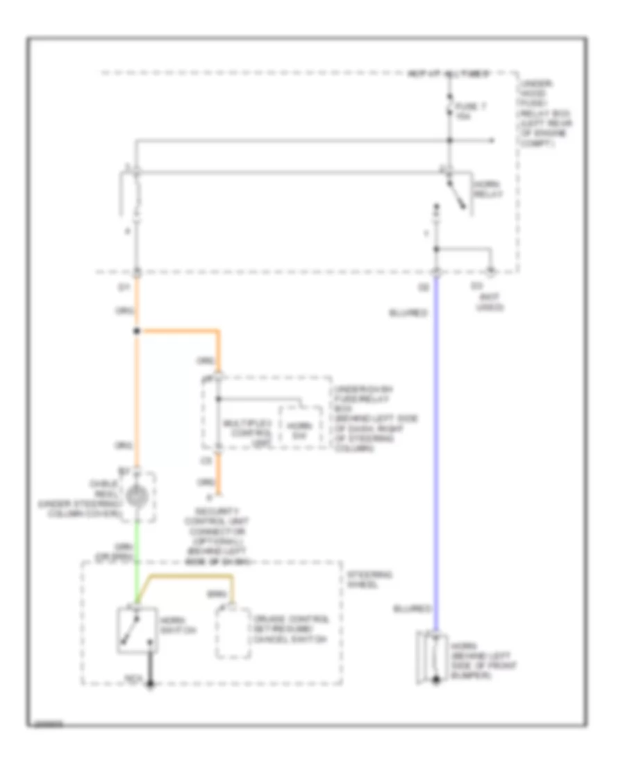
Horn Wiring Diagram for Honda Element LX 2007
List of elements for Horn Wiring Diagram for Honda Element LX 2007:
- (not used)
- Cable reel (under steering column cover)
- Cruise control set/resume/ cancel switch
- Fuse 7 15a
- Horn (behind left side of front bumper)
- Horn relay
- Horn sw
- Horn switch
- Hot at all times
- Multiplex control unit
- Nca
- Security control unit connector (optional) (behind left side of dash)
- Steering wheel
- Under- hood fuse/ relay box (left rear of engine compt)
- Under-dash fuse/relay box (behind left side of dash, right of steering column)
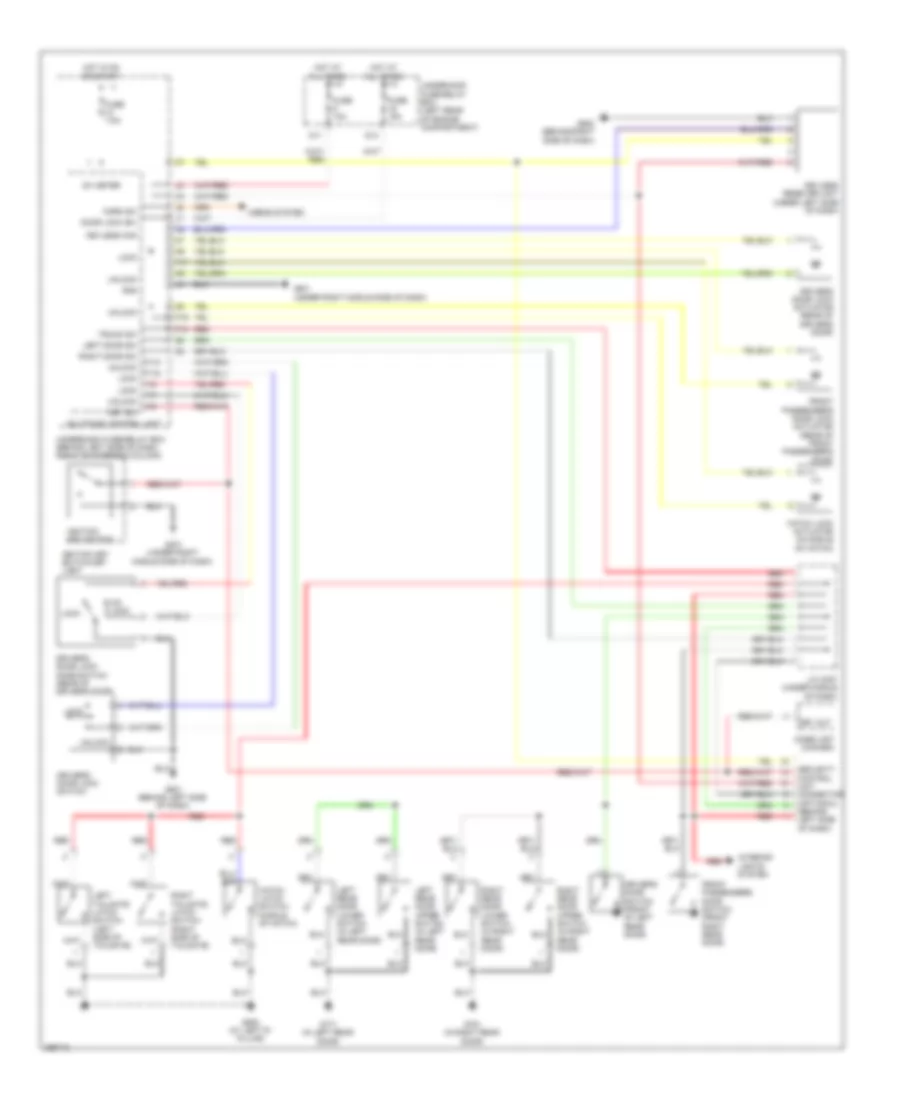
INSTRUMENT CLUSTER
Instrument Cluster Wiring Diagram (1 of 2) for Honda Element LX 2007
List of elements for Instrument Cluster Wiring Diagram (1 of 2) for Honda Element LX 2007:
- 10v stabilize circuit
- A/t indicator drive circuit
- Abs ind
- Anti-lock brakes system
- Anti-theft system
- Area network controller 5v stabilize circuit/controller
- Beeper
- Brake system ind
- Charging system ind
- Compulsory turn on circuit
- Compulsory turning-on circuit
- Computer data lines system
- Cruise control ind
- Cruise control system
- D11
- Daytime running lights ind
- Dial face back light (white)
- Drive circuit
- Engine coolant temperature gauge
- Exterior lights system
- F-can transceiver
- Fail-safe circuit
- Fog light ind
- Fuel gauge
- Fuel gauge sending unit
- Fuel tank unit (in fuel tank)
- Fuse 9 10a
- G502 (behind right side of dash)
- Gauge control module
- Headlights system
- High beam ind
- Hot at all times
- I/f
- Illumination control circuit
- Immobilizer system ind
- Interior lights system
- Lcd back light
- Lcd back light (red) (x2)
- Lcd back light (white) (x7)
- Lcd back light (x10)
- Lcd back light (x18)
- Lcd driver
- Left turn signal ind
- Lights on ind
- Low fuel ind
- Low oil pressure ind
- Low tire pressure ind
- Maintenance required ind
- Mil ind
- Odometer, trip a/trip b, check fuel, door ajar, smart maintenance
- Pointer illumi- nation
- Red
- Right turn signal ind
- Rotary encoder switch
- Seat belt reminder ind
- Side air bag cut-off ind
- Small light dimming
- Speedometer
- Srs ind
- Switched b+
- Tachometer
- Tpms ind
- Uart transceiver
- Under-hood fuse/relay box (left rear of engine compt)
- Vsa activation ind
- Vsa ind
- Warning drive circuit
- Washer fluid level ind (canada)
Instrument Cluster Wiring Diagram (2 of 2) for Honda Element LX 2007
List of elements for Instrument Cluster Wiring Diagram (2 of 2) for Honda Element LX 2007:
- (sc)
- Brake fluid level switch (on brake fluid reservoir)
- Brake level sw
- Canada
- Drl control unit
- Fuse 10 7.5a
- Fuse 15 15a 20a
- G201 (behind right side of front bumper)
- G401 (under right middle side of dash)
- Hot in run or start
- Hot w/ head light switch in head or park
- K10
- K13
- Multiplex control unit
- Oil pressure switch (right front of engine)
- Parking brake switch (lx & ex: under center console) (sc: base of parking brake lever)
- Under-dash fuse/relay box (behind left side of dash, right of steering column)
- Usa
- Washer fluid level switch (canada)
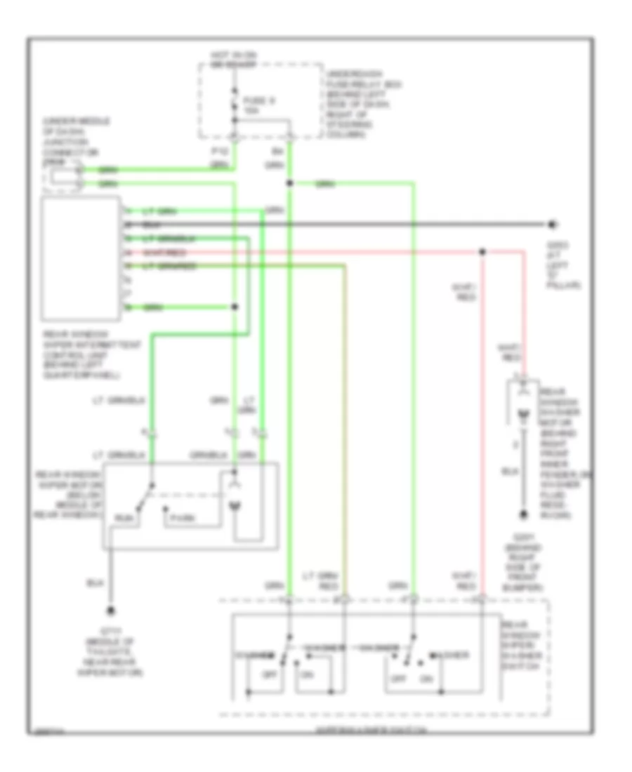
INTERIOR LIGHTS
Courtesy Lamps Wiring Diagram for Honda Element LX 2007
List of elements for Courtesy Lamps Wiring Diagram for Honda Element LX 2007:
- (behind left side of dash) g501
- (under right middle side of dash) g401
- Anti-theft system
- Canada
- D/l sil-con sw (l0ck)
- D/l sil-con sw (unl0ck)
- Door
- Door lock knob
- Driver's door lock knob switch (rear of driver's door)
- Driver's door switch (front of left rear door)
- Front ceiling light
- Front pass- enger's door switch (front of right rear door)
- Fuse 3 7.5a
- Fuse 7.5a
- G553 (at left "d" pillar)
- G751 (in right rear door)
- G771 (in left rear door)
- Hatch latch switch (ex & sc) (middle of hatch)
- Hot at all times
- Hot in on or start
- Ig1
- Ignition key light
- Ignition key switch
- Ignition key switch/key light
- Int lts
- J/c c457 (under middle of dash)
- Key
- Key lt-
- Key sw
- Left door sw
- Left rear door lower switch (in left rear door)
- Left rear door upper switch (in left rear door)
- Left tailgate latch switch (ex & sc) (left side of tailgate)
- Multiplex control unit
- Off
- P18
- P3 (not used)
- Rear ceiling light (ex & sc)
- Rear ceiling light diode (ex & sc) (under left side of dash)
- Red
- Right door sw
- Right rear door lower switch (in right rear door)
- Right rear door upper switch (in right rear door)
- Right tailgate latch switch (ex & sc) (right side of tailgate)
- Security control unit connector (optional) (behind left side of dash)
- Spotlights (ex & sc)
- Trunk sw
- Under-dash fuse/relay box (behind left side of dash, right of steering column)
- Under-hood fuse/relay box (left rear of engine compartment)
Instrument Illumination Wiring Diagram for Honda Element LX 2007
List of elements for Instrument Illumination Wiring Diagram for Honda Element LX 2007:
- (not used)
- 10v stabilize circuit
- 5v stabilize circuit/ controller area network controller
- A/t shift lever illumination
- A/t shift lever illumination/park pin switch (a/t)
- A19
- Audio unit
- C11
- Combination light switch
- Cruise control main switch
- D11
- Dial face back light (white)
- Exterior lights system
- Front passenger's air bag cut-off indicator
- Fuse 10a
- Fuse 15a
- G401 (under right middle side of dash)
- G502 (behind right side of dash)
- Gauge control module
- Hazard warning switch
- Head
- Headlight switch
- Heater control panel
- Hot at all times
- Ill +
- K11
- K17
- L10
- Lcd back light
- Lcd back light (red) (x2)
- Lcd back light (white) (x7)
- Lcd back light (x10)
- Lcd back light (x18)
- Lt rly -
- Multiplex control unit
- O10
- Off
- P11
- P15
- Park
- Pointer illumi- nation
- Power mirror switch
- Red
- Security control unit connector (optional) (behind left side of dash)
- Small
- Taillight relay
- Under-dash fuse/relay box (behind left side of dash, right of steering column)
- Under-hood fuse/relay box (left rear of engine compartment)
- V4 option conn- ector
- Vsa off switch
POWER DISTRIBUTION
Power Distribution Wiring Diagram (1 of 4) for Honda Element LX 2007
List of elements for Power Distribution Wiring Diagram (1 of 4) for Honda Element LX 2007:
- (left rear of engine compt) underhood fuse/relay box
- (not used)
- +b back up
- A/c compressor clutch relay
- A/c condenser fan relay
- A10
- Alternator
- Audio unit
- Battery
- Brake pedal position switch
- C10
- D11
- Data link connector (dlc)
- E12
- Eld unit
- From battery a (diagram 1 of 4)
- Front ceiling light
- Fuse 100a
- Fuse 10a
- Fuse 15a
- Fuse 20a
- Fuse 30a
- Fuse 50a
- Fuse 7.5a
- Gauge control module
- Hazard warning switch
- Horn relay
- Ignition key switch/ key light
- Immobilizer control unit- receiver
- Imoes unit (except 2007 usa)
- J/c c559 (under middle of dash)
- K13
- Keyless receiver unit
- Multiplex control unit
- Pgm-fi main relay 1
- Radiator fan relay
- Rear ceiling light
- Security control unit connector (optional)
- Spotlights (ex & sc)
- Starter
- Starter solenoid
- T101
- T102
- Taillight relay
- Throttle actuator control module relay
- To ignition switch (diagram 3 of 4)
- To underhood fuse/relay box (fuse 13) (diagram 2 of 4)
- To underhood fuse/relay box (fuse 5) (diagram 1 of 4)
- To underhood fuse/relay box (headlight relay 2) (diagram 2 of 4)
- Trailer lighting control unit connector (optional)
- Underdash fuse/relay box (behind left side of dash, right of steering column)
- Underhood fuse/relay box (left rear of engine compt)
- Vsa modulator control unit
- Xm receiver (usa: ex & sc)
Power Distribution Wiring Diagram (2 of 4) for Honda Element LX 2007
List of elements for Power Distribution Wiring Diagram (2 of 4) for Honda Element LX 2007:
- (left rear of engine compt) underhood fuse/relay box
- (used for fog lights)
- +b day lt
- +b door lock
- +b rr fog
- A/f sensor relay
- A11
- Blower motor relay
- Console accessory power socket
- D14
- Drl control unit (canada)
- Ex & sc
- F11
- From underdash fuse/relay box (diagram 3 of 4)
- From underhood fuse/relay box b (fuse 9) (diagram 1 of 4)
- From underhood fuse/relay box c (fuse 6) (diagram 1 of 4)
- Front accessory power socket
- Fuse (not used)
- Fuse 10a
- Fuse 15a
- Fuse 20a
- Fuse 40a
- G451 (behind left center of dash)
- G502 (behind right side of dash)
- G551 (at right "d" pillar)
- G552 (under front passenger's seat)
- Headlight relay (lx & ex)
- Headlight relay 1 (sc)
- Headlight relay 2 (sc)
- Ignition coil relay
- Multiplex control unit
- P10
- Rear accessory power socket
- Rear accessory power socket relay
- Rear window defogger relay
- Stereo amplifier
- To power window relay (diagram 4 of 4)
- Tpms control unit
- Underdash fuse/relay box (behind left side of dash, right of steering column)
- Underhood fuse/relay box (left rear of engine compt)
Power Distribution Wiring Diagram (3 of 4) for Honda Element LX 2007
List of elements for Power Distribution Wiring Diagram (3 of 4) for Honda Element LX 2007:
- (behind left side of dash, right of steering column) underdash fuse/relay box
- (not used)
- A/c compressor clutch relay
- A/c condenser fan relay
- A/t
- A/t reverse relay
- A17
- A18
- Acc
- Audio unit
- Back-up light switch
- Blower motor relay
- Canada
- D11
- D12
- Drl control unit
- Ecm/ pcm
- From underdash fuse/relay box (diagram 1 of 4)
- Front passenger's air bag cut- off indicator
- Fuse (not used)
- Fuse 10a
- Fuse 15a
- Fuse 20a
- Fuse 7.5a
- Gauge control module
- Hazard warning switch
- Heater control panel
- Ig1 meter
- Ig1 wiper
- Ig2 day lt
- Ignition switch
- Immobilizer control unit receiver
- Imoes unit (except 2007 usa)
- J/c c559 (under middle of dash)
- K12
- K14
- Keyless receiver unit
- Lock
- M/t
- Multiplex control unit
- Ods unit
- Option connector
- P12
- Pgm-fi main relay 2
- Power mirror switch
- Radiator fan relay
- Rear window defogger relay
- Rear window wiper intermittent control unit
- Rear window wiper motor
- Recirculation control motor
- Security control unit connector (optional)
- Shift lock solenoid/ d3 switch
- Srs unit
- Start
- Starter cut relay
- To underdash fuse relay box (fuse 18) (diagram 2 of 4)
- To underdash fuse/relay box (diagram 4 of 4)
- Tpms control unit
- Underdash fuse/relay box (behind left side of dash, right of steering column)
- Underhood fuse/relay box (left rear of engine compt)
- Windshield wiper motor
- Wiper/ washer switch
- Wiper/washer switch
Power Distribution Wiring Diagram (4 of 4) for Honda Element LX 2007
List of elements for Power Distribution Wiring Diagram (4 of 4) for Honda Element LX 2007:
- (behind left side of dash, right of steering column) underdash fuse/relay box
- (not used)
- Alternator
- Brake pedal position switch
- Cmp sensor a
- Cruise control main switch
- Eld unit
- Evap canister purge valve
- From underdash fuse/relay box (diagram 2 of 4)
- From underdash g fuse/relay box (diagram 3 of 4)
- Fuse (not used)
- Fuse 10a
- Fuse 20a
- Fuse 7.5a
- J/c c105 (left rear of engine)
- J/c c405 (under middle of dash)
- J/c c457 (under middle of dash)
- M10
- Maf/iat sensor
- Power window master switch
- Power window relay
- Secondary ho2s
- Underhood fuse/relay box (left rear of engine compt)
- Vsa modulator control unit
POWER DOOR LOCKS
Power Door Locks Wiring Diagram for Honda Element LX 2007
List of elements for Power Door Locks Wiring Diagram for Honda Element LX 2007:
- D11
- D14
- Door lock (b+)
- Driver's door lock actuator (rear of driver's door)
- Driver's door lock knob switch (rear of driver's door)
- Driver's door lock switch
- Driver's door switch (front of left rear door)
- Front passenger's door lock actuator (rear of front passenger's door)
- Front passenger's door switch (front right rear door)
- Fuse 10a
- Fuse 15a
- Fuse 7.5a
- G401 (under right middle side of dash)
- G501 (behind left side of dash)
- G502 (behind right side of dash)
- G553 (at left "d" pillar)
- G751 (in right rear door)
- G771 (in left rear door)
- Gnd
- Hatch latch switch (middle of hatch)
- Hatch lock actuator (in middle of hatch)
- Horn sw
- Horns system
- Hot at all times
- Hot in on or start
- Ig1 meter
- Ignition key switch
- Ignition key switch/key light
- Imoes unit (canada)
- Interior lights system
- J/c c457 (under middle of dash)
- Key out
- Key sw
- Keyless com
- Keyless receiver unit (under left side of dash)
- Left door sw
- Left rear door lower switch (in left rear door)
- Left rear door upper switch (in left rear door)
- Left tailgate latch switch (left side of tailgate)
- Lock
- Multiplex control unit
- P16
- P17
- P18
- Red
- Right door sw
- Right rear door lower switch (in right rear door)
- Right rear door upper switch (in right rear door)
- Right tailgate latch switch (right side of tailgate)
- Security control unit connector (optional) (behind left side of dash)
- Trunk sw
- Un- lock
- Underdash fuse/relay box (behind left side of dash, right of steering column)
- Underhood fuse/relay box (left rear of engine compartment)
- Unlock
- Y10
- Y12
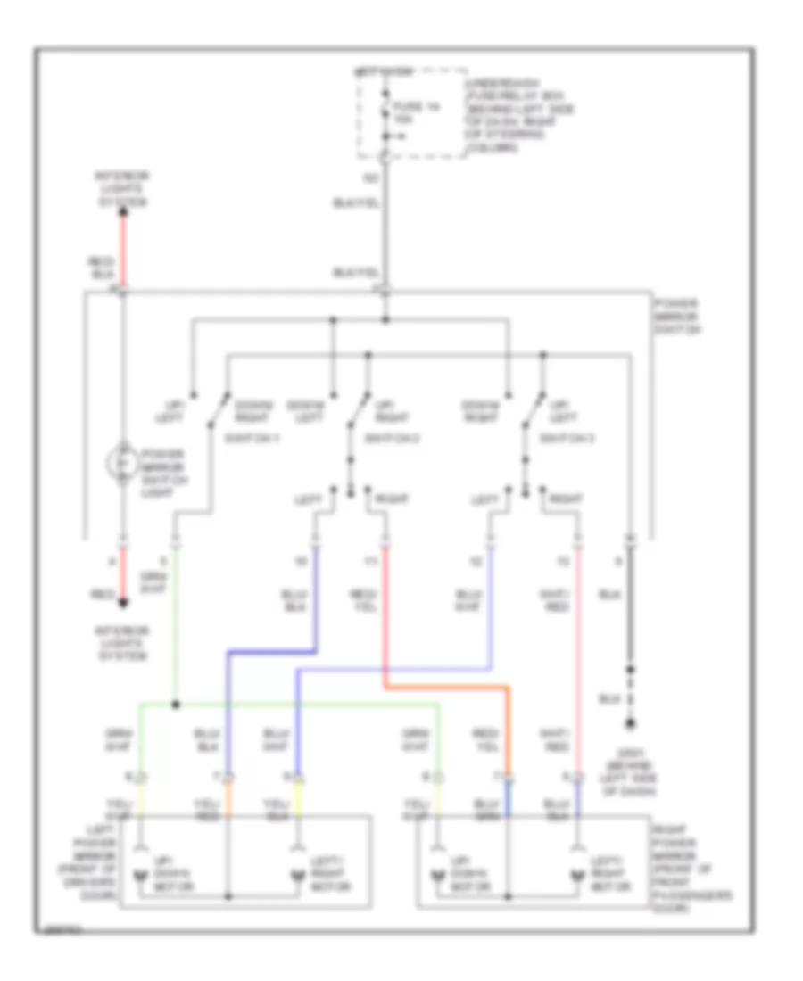
POWER MIRRORS
Power Mirrors Wiring Diagram for Honda Element LX 2007
List of elements for Power Mirrors Wiring Diagram for Honda Element LX 2007:
- Down/ left
- Down/ right
- Fuse 14 10a
- G501 (behind left side of dash)
- Hot in on
- Interior lights system
- Left
- Left power mirror (front of driver's door)
- Left/ right motor
- Power mirror switch
- Power mirror switch light
- Red
- Right
- Right power mirror (front of front passenger's door)
- Switch 1
- Switch 2
- Switch 3
- Underdash fuse/relay box (behind left side of dash, right of steering column)
- Up/ down motor
- Up/ left
- Up/ right
POWER WINDOWS
Power Windows Wiring Diagram for Honda Element LX 2007
List of elements for Power Windows Wiring Diagram for Honda Element LX 2007:
- (not used)
- Down
- Down+
- Driver's power window motor (in driver's door)
- Driver's switch 0=off 1=on 2=down 3=auto up 4=auto down
- Front passenger's power window motor (in right front door)
- Front passenger's power window switch
- Fuse 13 40a
- Fuse 22 20a
- Fuse 23 20a
- Fuse 25 (not used)
- Fuse 6 7.5a
- G401 (under right middle side of dash)
- G501 (behind left side of dash)
- Hot at all times
- Hot in on or start
- M10
- M11
- Main switch
- Mil ctrl
- Off
- P13
- Plsa
- Plsb
- Power window control unit
- Power window master switch
- Power window relay
- Pulser
- Red
- Sgnd
- Svcc
- Underdash fuse/relay box (behind left side of dash, right of steering column)
- Underhood fuse/relay box (left rear of engine compt)
- Up+
RADIO
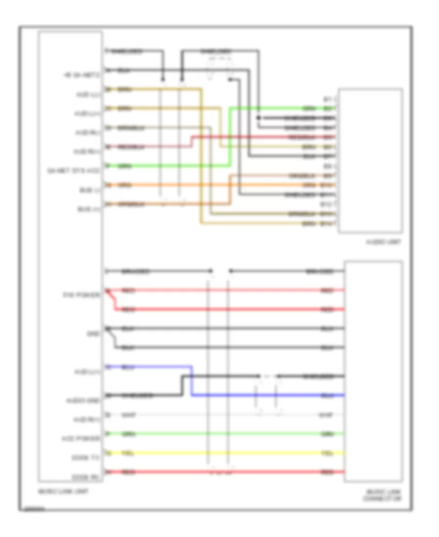
Music Link Wiring Diagram, Accessory for Honda Element LX 2007
List of elements for Music Link Wiring Diagram, Accessory for Honda Element LX 2007:
- +b ga-net2
- Acc power
- Aud l(+)
- Aud l(-)
- Aud r(+)
- Aud r(-)
- Audio gnd
- Audio unit
- B10
- B11
- B12
- B13
- B14
- Braided
- Bus (+)
- Bus (-)
- Dock rx
- Dock tx
- F/w power
- Ga-net sys acc
- Gnd
- Music link connector
- Music link unit
- Red
- Shielded
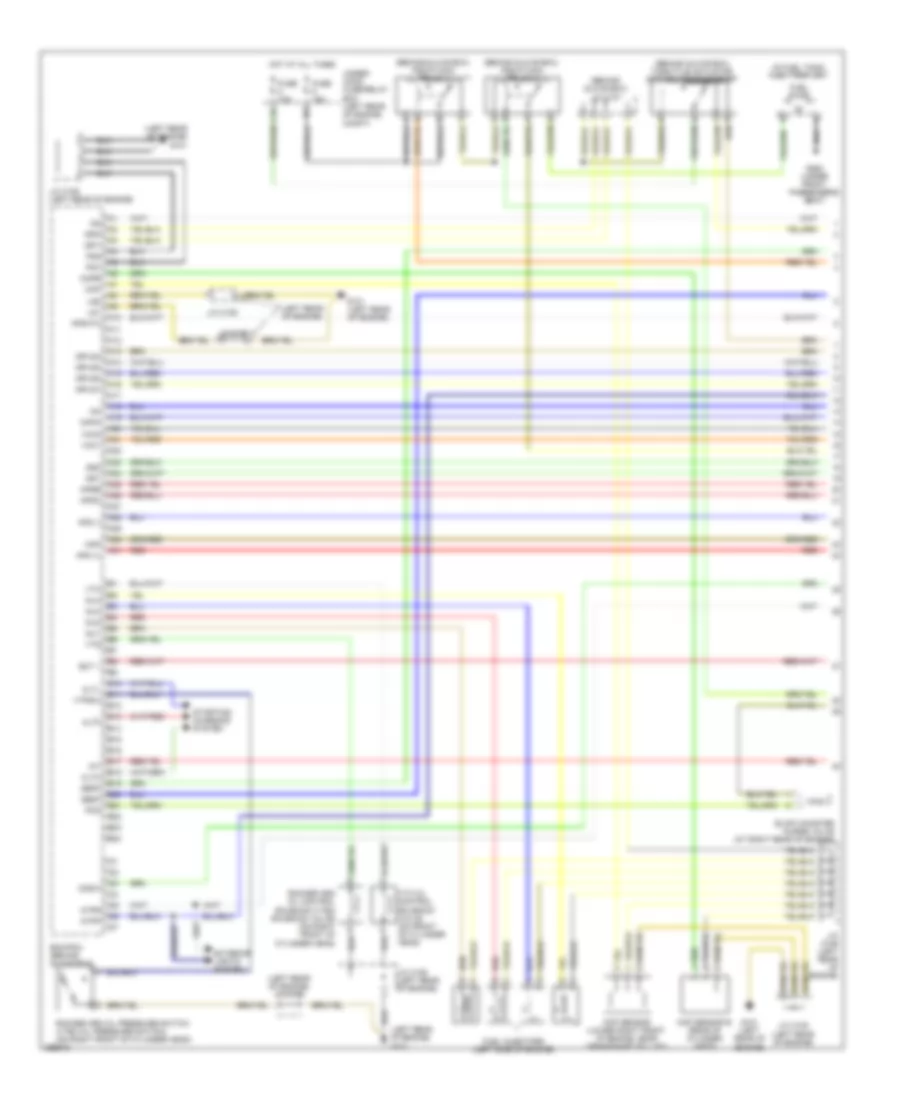
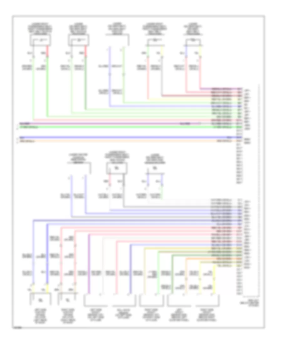
Radio Wiring Diagram, Canada: EX & SC (1 of 2) for Honda Element LX 2007
List of elements for Radio Wiring Diagram, Canada: EX & SC (1 of 2) for Honda Element LX 2007:
- (not used)
- (or nca)
- (sc)
- (under middle of dash) g503
- (under right side of dash) antenna lead connector
- A10
- A11
- A12
- A13
- A14
- A15
- A16
- A17
- A18
- A19
- A20
- Acc
- Acc radio
- Am/fm antenna
- Am/fm antenna mast
- Ant gnd
- Ant in
- Audio unit
- Aux s-gnd
- Aux-det
- Aux-gnd
- Aux-lch
- Aux-rch
- Auxiliary jack assembly
- B+ back up
- B10
- B11
- B12
- B13
- B14
- Cd changer (if equipped)
- D11
- Fl sp+
- Fl sp-
- Fr sp+
- Fr sp-
- Fuse 20a
- Fuse 7.5a
- Fuse 9 10a
- Hot at all times
- Hot in acc or on
- Iilum ctrl
- Illum +
- Interior lights system
- Main gnd
- Multiplex control unit
- Nca
- Pnk
- Red
- Remote
- Remote gnd
- Rl sp+
- Rl sp-
- Rr sp+
- Rr sp-
- Shield gnd
- Swbw +
- Swbw -
- Swd +b
- Under-dash fuse/relay box (behind left side of dash, right of steering column)
- Under-hood fuse/relay box (left reae of engine compt)
- W/ cd changer
- W/o cd changer
Radio Wiring Diagram, Canada: EX & SC (2 of 2) for Honda Element LX 2007
List of elements for Radio Wiring Diagram, Canada: EX & SC (2 of 2) for Honda Element LX 2007:
- (under middle of dash) g503
- A10
- A11
- A12
- A13
- A14
- Audio remote switch
- B10
- B11
- B12
- B13
- B14
- B15
- B16
- Cable reel (under steering column cover)
- Channel switch
- Driver's door speaker
- Fl out (+)
- Fl out (-)
- Fl sp+
- Fl sp-
- Fr out (+)
- Fr out (-)
- Fr sp+
- Fr sp-
- Front passenger's door speaker
- Gnd
- Left rear door speaker
- Left tweeter
- Mode switch
- Pnk
- Red
- Right rear door speaker
- Right tweeter
- Rl out (+)
- Rl out (-)
- Rl sp+
- Rl sp-
- Rr out (+)
- Rr out (-)
- Rr sp+
- Rr sp-
- Steering wheel
- Stereo amplifier (right kick panel)
- Sub wf1 out+
- Sub wf1 out-
- Sub wf2 out+
- Sub wf2 out-
- Subwoofer
- Swbw +
- Swbw -
- Swd +b
- Volume down switch
- Volume up switch
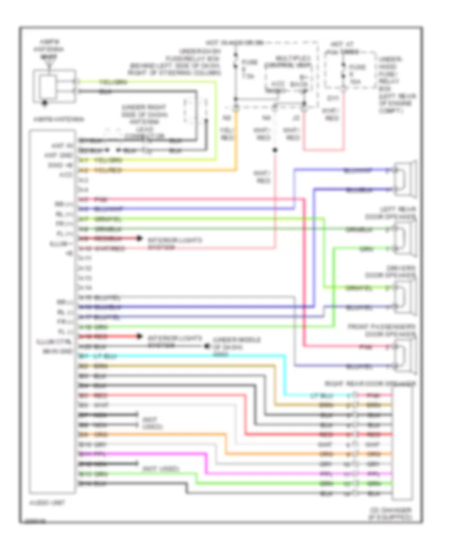
Radio Wiring Diagram, LX for Honda Element LX 2007
List of elements for Radio Wiring Diagram, LX for Honda Element LX 2007:
- (not used)
- (under middle of dash) g503
- (under right side of dash) antenna lead connector
- A10
- A11
- A12
- A13
- A14
- A15
- A16
- A17
- A18
- A19
- A20
- Acc
- Acc radio
- Am/fm antenna
- Am/fm antenna mast
- Ant gnd
- Ant in
- Audio unit
- B+ back up
- B10
- B11
- B12
- B13
- B14
- Cd changer (if equipped)
- D11
- Driver's door speaker
- Fl (+)
- Fl (-)
- Fr (+)
- Fr (-)
- Front passenger's door speaker
- Fuse 10a
- Fuse 7.5a
- Hot at all times
- Hot in acc or on
- Illum +
- Illum ctrl
- Interior lights system
- Left rear door speaker
- Main gnd
- Multiplex control unit
- Nca
- Pnk
- Red
- Right rear door speaker
- Rl (+)
- Rl (-)
- Rr (+)
- Rr (-)
- Swd +b
- Under- hood fuse/ relay box (left rear of engine compt)
- Under-dash fuse/relay box (behind left side of dash, right of steering column)
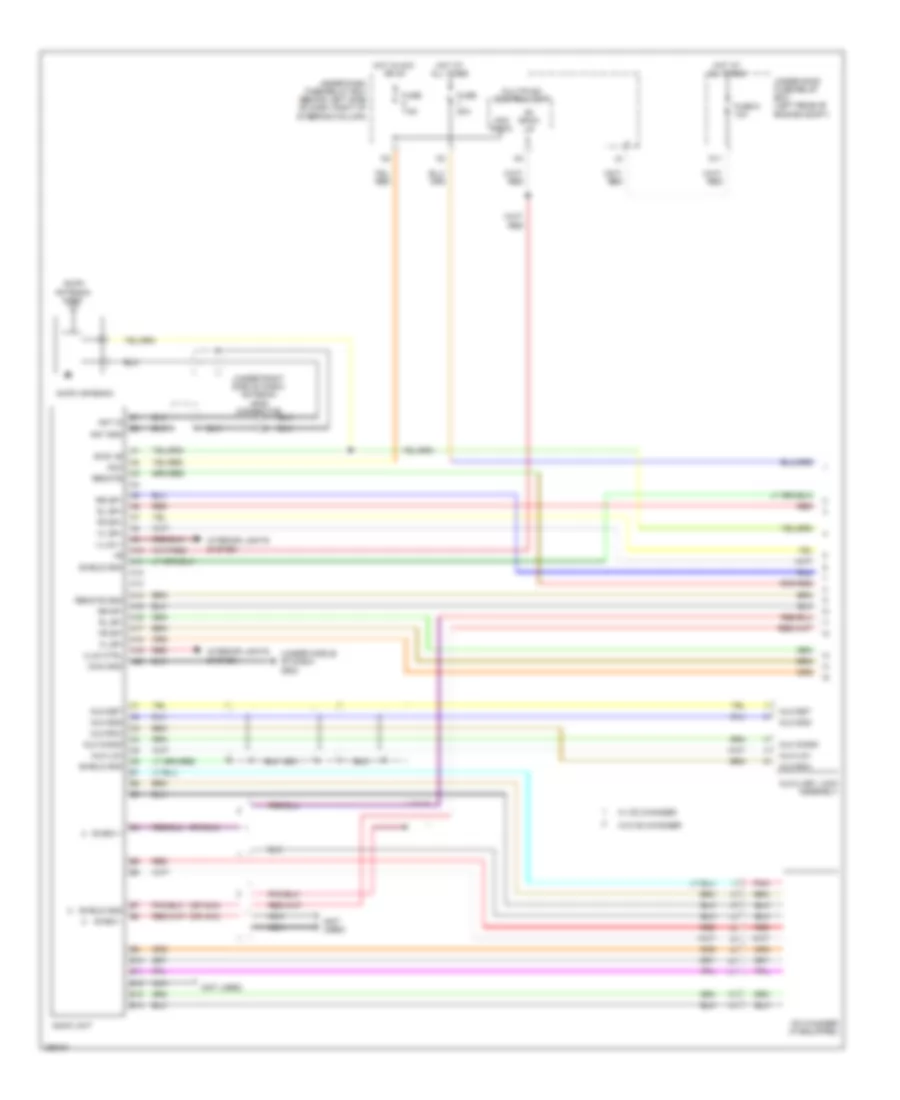
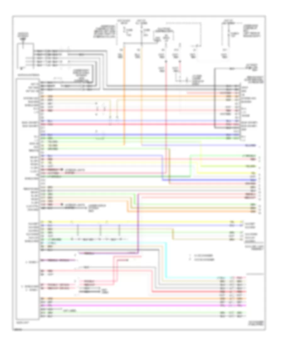
Radio Wiring Diagram, USA: EX & SC (1 of 2) for Honda Element LX 2007
List of elements for Radio Wiring Diagram, USA: EX & SC (1 of 2) for Honda Element LX 2007:
- (at right "d" pillar) g551
- (behind right quarterpanel) xm receiver
- (not used)
- (or nca)
- (sc)
- (under middle of dash) g503
- (under right side of dash) antenna lead connector
- +b sub
- A10
- A11
- A12
- A13
- A14
- A15
- A16
- A17
- A18
- A19
- A20
- Acc
- Acc radio
- Am/fm/xm antenna
- Am/fm/xm antenna mast
- Ant gnd
- Ant in
- Ant sw +b
- Audio unit
- Aux s-gnd
- Aux-det
- Aux-gnd
- Aux-lch
- Aux-rch
- Auxiliary jack assembly
- B+ back up
- B10
- B11
- B12
- B13
- B14
- Bus gnd
- Bus+ (ga-net)
- Bus- (ga-net)
- Cd changer (if equipped)
- D10
- D11
- D12
- D13
- D14
- Fl sp+
- Fl sp-
- Fr sp+
- Fr sp-
- Fuse 20a
- Fuse 7.5a
- Fuse 9 10a
- Gnd
- Hot at all times
- Hot in acc or on
- Iilum ctrl
- Illum +
- Input
- Interior lights system
- J/c c559 (under middle of dash)
- K13
- L (+)
- L (-)
- Main gnd
- Multiplex control unit
- Nca
- Pnk
- R (+)
- R (-)
- Red
- Remote
- Remote gnd
- Rl sp+
- Rl sp-
- Rr sp+
- Rr sp-
- Shield gnd
- Swbw +
- Swbw -
- Swd +b
- System acc
- Under-dash fuse/relay box (behind left side of dash, right of steering column)
- Under-hood fuse/relay box (left rear of engine compt)
- W/ cd changer
- W/o cd changer
Radio Wiring Diagram, USA: EX & SC (2 of 2) for Honda Element LX 2007
List of elements for Radio Wiring Diagram, USA: EX & SC (2 of 2) for Honda Element LX 2007:
- (under middle of dash) g503
- A10
- A11
- A12
- A13
- A14
- Audio remote switch
- B10
- B11
- B12
- B13
- B14
- B15
- B16
- Cable reel (under steering column cover)
- Channel switch
- Driver's door speaker
- Fl out (+)
- Fl out (-)
- Fl sp+
- Fl sp-
- Fr out (+)
- Fr out (-)
- Fr sp+
- Fr sp-
- Front passenger's door speaker
- Gnd
- Left rear door speaker
- Left tweeter
- Mode switch
- Pnk
- Red
- Right rear door speaker
- Right tweeter
- Rl out (+)
- Rl out (-)
- Rl sp+
- Rl sp-
- Rr out (+)
- Rr out (-)
- Rr sp+
- Rr sp-
- Steering wheel
- Stereo amplifier (right kick panel)
- Sub wf1 out+
- Sub wf1 out-
- Sub wf2 out+
- Sub wf2 out-
- Subwoofer
- Swbw +
- Swbw -
- Swd +b
- Volume down switch
- Volume up switch
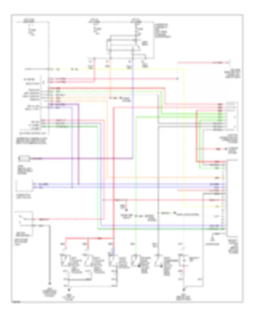
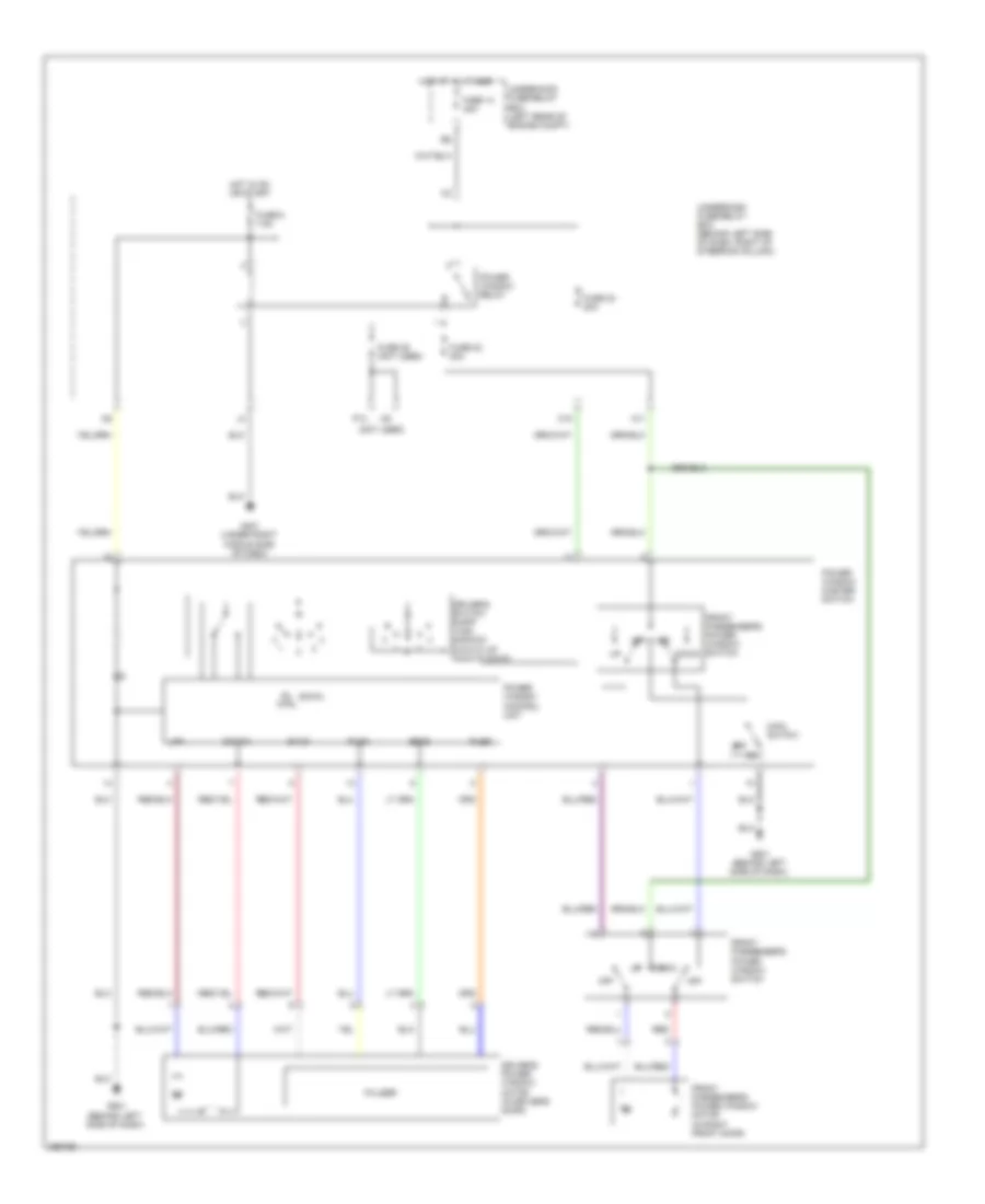
SHIFT INTERLOCK
Shift Interlock Wiring Diagram for Honda Element LX 2007
List of elements for Shift Interlock Wiring Diagram for Honda Element LX 2007:
- (not used)
- A/t shift lever illumination/park pin switch
- Atp-p
- Brake pedal position switch (on brake pedal support)
- D10
- D11
- Drive input (atp -n)
- E22
- Fuse 15a
- Fuse 7.5a
- G101 (left rear of engine)
- G401 (under right middle side of dash)
- Gnd
- Hot at all times
- Hot in on or start
- Ig1 meter
- Ignition key switch
- Ignition key switch/ key light
- Imoes unit (except 2007 usa)
- Interlock control output (sls)
- Junction connector c106 (left rear of engine)
- Key interlock solenoid
- Key lock sol +
- Key sw
- Multiplex control unit
- P-pin
- Park pin switch
- Pcm (behind glove box)
- Security control unit connector (optional)
- Shift lock solenoid
- Shift lock solenoid/ d3 switch (under middle of dash)
- Stop sw
- Switch input (bksw)
- Transmission range switch (on lower rear of transaxle)
- Underdash fuse/relay box (behind left side of dash, right of steering column)
- Underhood fuse/relay box (left rear of engine compt)
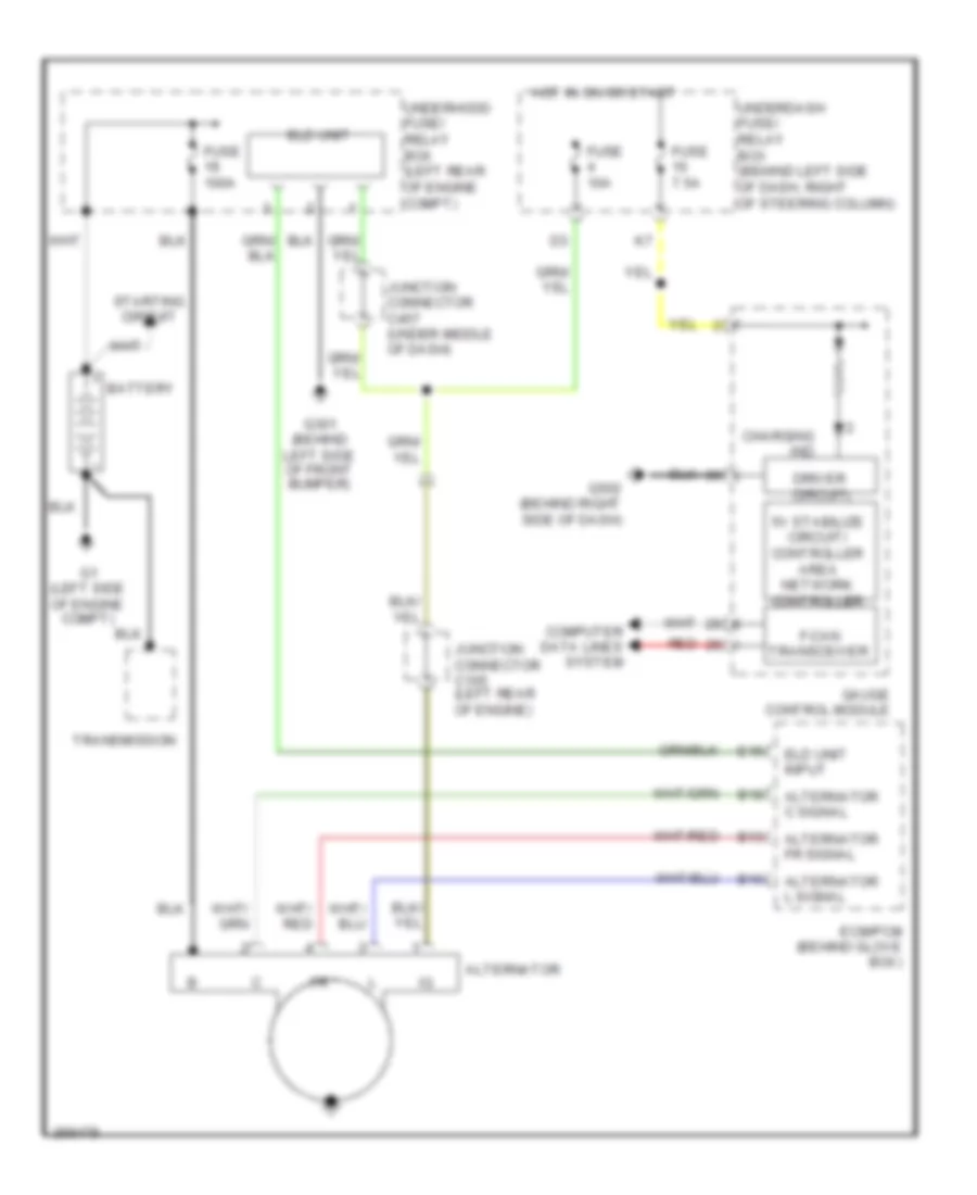
STARTING/CHARGING
Charging Wiring Diagram for Honda Element LX 2007
List of elements for Charging Wiring Diagram for Honda Element LX 2007:
- 5v stabilize circuit/ controller area network controller
- Alternator
- Alternator c signal
- Alternator fr signal
- Alternator l signal
- B10
- B13
- B18
- Battery
- Charging ind
- Computer data lines system
- Driver circuit
- E15
- Ecm/pcm (behind glove box)
- Eld unit
- Eld unit input
- F-can transceiver
- Fuse 100a
- Fuse 10a
- Fuse 7.5a
- G1 (left side of engine compt)
- G301 (behind left side of front bumper)
- G502 (behind right side of dash)
- Gauge control module
- Hot in on or start
- Junction connector c105 (left rear of engine)
- Junction connector c457 (under middle of dash)
- Red
- Starting circuit
- Transmission
- Underdash fuse/ relay box (behind left side of dash, right of steering column)
- Underhood fuse/ relay box (left rear of engine compt)
Starting Wiring Diagram for Honda Element LX 2007
List of elements for Starting Wiring Diagram for Honda Element LX 2007:
- (not used)
- A/t
- Acc
- Battery
- Clutch interlock switch (on clutch pedal support)
- E11
- Eld unit
- Fuse 19 100a
- Fuse 20 50a
- Fuse 21
- G1 (left side of engine compt)
- G101 (left rear of engine)
- G502 (behind right side of dash)
- Ignition switch
- Junction connector c106 (left rear of engine)
- Lock
- M/t
- Start
- Starter
- Starter cut relay
- Starter motor
- Starter solenoid
- Transmission
- Transmission range switch (on lower rear of transaxle)
- Underdash fuse/relay box (behind left side of dash, right of steering column)
- Underhood fuse/relay box (left rear of engine compt)
SUPPLEMENTAL RESTRAINTS
Supplemental Restraints Wiring Diagram (1 of 3) for Honda Element LX 2007
List of elements for Supplemental Restraints Wiring Diagram (1 of 3) for Honda Element LX 2007:
- 5v stabilize circuit/ controller area network controller
- A10
- A11
- A12
- A13
- A14
- A15
- A16
- A17
- A18
- A19
- A20
- A21
- A22
- A23
- A24
- A25
- A26
- A27
- A28
- Cable reel (under steering column cover)
- Cds
- Compulsory turn on circuit
- Computer data lines
- Data link connector (dlc) (under left side of dash)
- Driver's air bag first inflator (center of steering wheel)
- Driver's air bag second inflator (center of steering wheel)
- Front passenger's air bag cut-off indicator
- Front passenger's air bag first inflator (right side of dash)
- Front passenger's air bag second inflator (right side of dash)
- Fuse 10a
- Fuse 15a
- Fuse 7.5a
- G402 (under left middle side of dash)
- G451 (behind left center of dash)
- G502 (behind right side of dash)
- Gauge control module
- Hot in on or start
- Idc
- Indicator light
- J/c c559 (under middle of dash)
- K-line
- K12
- La1 +
- La1 -
- La2 +
- La2 -
- Left front impact sensor (behind left side of front bumper)
- Lfs +
- Lfs -
- Mes
- Mes connector (under left side of dash)
- Ods
- P12
- Ptt
- Ra1 +
- Ra1 -
- Ra2 +
- Ra2 -
- Red
- Rfs +
- Rfs -
- Right front impact sensor (behind right side of front bumper)
- Scs
- Side air bag cut-off indicator
- Srs gnd (1)
- Srs gnd (2)
- Srs indicator
- Srs unit (below center of dash)
- Steering wheel
- Uart transceiver
- Under-dash fuse/relay box (behind left side of dash, right of steering column)
Supplemental Restraints Wiring Diagram (2 of 3) for Honda Element LX 2007
List of elements for Supplemental Restraints Wiring Diagram (2 of 3) for Honda Element LX 2007:
- (lower four
- (right side of
- (under front passenger's seat) inner side front passenger's weight sensor
- (under front passenger's seat) outer side front passenger's weight sensor
- (upper two sensors in seat back)
- Bus meter
- D10
- D11
- D12
- D13
- D14
- D15
- D16
- D17
- D18
- Dr belt sw
- Driver's seat belt buckle switch
- Front passenger's seat belt buckle switch
- G552 (under front passenger's seat)
- Gnd
- J/c c457 (under middle of dash)
- K10
- Lower element
- Micu
- Nca
- Ods
- Ods unit (in side of front passenger's seat)
- Opds sensor
- Os1l
- Os1s
- Os2l
- Os2s
- Os3l
- Os3s
- Os4l
- Os4s
- Os5l
- Os5s
- Os6l
- Os6s
- Os7l
- Os7s
- Pow
- Red
- Seat back)
- Seat belt buckled
- Seat belt unbuckled
- Sensors in seat back)
- Side element
- Under-dash fuse/relay box (behind left side of dash, right of steering column)
- Upper element
- Wrn
- Wsig
- Wsip
- Wsog
- Wsop
Supplemental Restraints Wiring Diagram (3 of 3) for Honda Element LX 2007
List of elements for Supplemental Restraints Wiring Diagram (3 of 3) for Honda Element LX 2007:
- (under center console) rear safing sensor
- (under driver's seat) driver's seat belt buckle tensioner
- (under driver's seat) driver's seat belt tensioner
- (under driver's seat) driver's seat position sensor
- (under driver's seat) driver's side air bag inflator
- (under front passenger's seat) front passenger's seat belt buckle tensioner
- (under front passenger's seat) front passenger's seat belt tensioner
- (under front passenger's seat) front passenger's side air bag inflator
- B10
- B11
- B12
- B13
- B14
- B15
- B16
- B17
- B18
- B19
- B20
- B21
- B22
- B23
- B24
- B25
- B26
- B27
- B28
- C10
- C11
- C12
- C13
- C14
- C15
- C16
- C17
- C18
- C19
- C20
- C21
- C22
- C23
- C24
- C25
- C26
- C27
- C28
- Lbp +
- Lbp -
- Lbsc
- Lbsi +
- Lbsi -
- Lbso
- Lca +
- Lca -
- Lcsi +
- Lcsi -
- Left impact sensor (2nd) (behind left quarter panel)
- Left side curtain air bag inflator (left rear of roof)
- Left side impact sensor (1st) (on left side of floor)
- Lrp +
- Lrp -
- Lsa +
- Lsa -
- Rbp +
- Rbp -
- Rbsc
- Rbsi +
- Rbsi -
- Rbso
- Rca +
- Rca -
- Rcsi +
- Rcsi -
- Red
- Right side curtain air bag inflator (right rear of roof)
- Right side impact sensor (1st) (on right side of floor)
- Right side impact sensor (2nd) (behind right quarter panel)
- Roll rate sensor (on left side of floor)
- Rrp +
- Rrp -
- Rrs +
- Rrs -
- Rsa +
- Rsa -
- Srs unit (below center of dash)
- Ss +
- Ss -
- Sss +
- Sss -
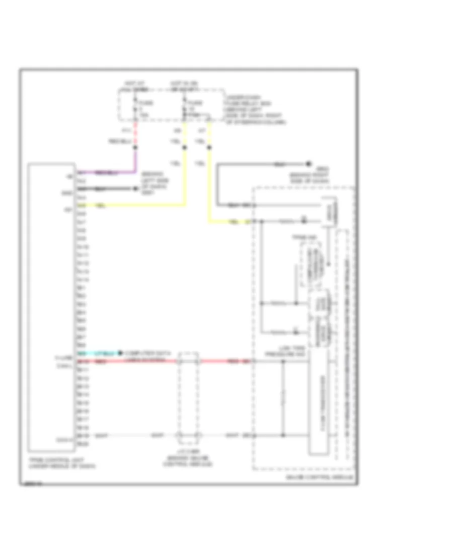
TRANSMISSION
A/T Wiring Diagram for Honda Element LX 2007
List of elements for A/T Wiring Diagram for Honda Element LX 2007:
- (behind glove box) pcm
- (behind glove box) pgm-fi main relay 1
- (behind right side of dash) g502
- (left rear of engine) j/c c106
- (left side of transaxle)
- (on lower rear of transaxle) transmission range switch
- (top of transaxle)
- (under middle of dash) shift lock solenoid/d3 switch
- 2nd clutch trans- mission fluid pressure switch (top of transaxle)
- 3rd clutch trans- mission fluid pressure switch (rear of transaxle)
- 5v stabilize circuit/ controller area network controller
- A/t clutch pressure control solenoid valve a
- A/t clutch pressure control solenoid valve b
- A/t clutch pressure control solenoid valve c
- A/t indicator drive circuit
- A/t reverse relay (behind glove box)
- A18
- A20
- A21
- A23
- A24
- A25
- A26
- A30
- App sensor (right rear corner of engine compartment)
- Apsa
- Apsb
- Atf temperature sensor
- Atft
- Atp-p
- Atp1
- Atp2
- Atpd
- Atpfwd
- Atpn
- Atpp
- Atpr
- Atprvs
- Bksw
- Brake pedal position switch (on brake pedal support)
- C10
- C11
- C12
- C13
- C14
- C15
- C17
- C18
- C19
- C20
- Can-h
- Can-l
- Compulsory turning on circuit
- Computer data lines system
- D10
- D11
- D3 switch
- D3sw
- E11
- E22
- E24
- Ect 1
- Ect sensor 1 (rear of cylinder head)
- Engine controls system
- Engine)
- F-can transceiver
- Fail safe circuit
- Fuse 10a
- Fuse 15a
- Fuse 7.5a
- G101 (left rear of engine)
- G451 (behind left center of dash)
- Gauge control module
- Hot at all times
- Hot in on or start
- Ig1
- Igp1
- Igp2
- Illumination control circuit
- Input shaft (mainshaft) speed sensor (right rear of transaxle)
- J/c c105 (left rear of engine)
- J/c c106 (left rear of engine)
- J/c c107 (behind glove box)
- Lg1
- Lg2
- Lsa
- Lsb
- Lsc
- Map
- Map sensor (left side of intake manifold)
- Mrly
- Multiplex control unit
- Op2sw
- Op3sw
- Output shaft (countershaft) speed sensor (right front of transaxle)
- Pg1
- Pg2
- Pnk
- Red
- Sg1
- Sg2
- Sha
- Shb
- Shc
- Shd
- She
- Shift control solenoid valves
- Starter cut relay
- Switched b+
- Transmission housing
- Under-dash fuse/relay box (behind left side of dash, right of steering column)
- Underhood fuse/relay box (left rear of engine compartment)
- Vcc1
- Vcc2
WARNING SYSTEMS
Chime Wiring Diagram for Honda Element LX 2007
List of elements for Chime Wiring Diagram for Honda Element LX 2007:
- +b back up
- 5v stabilize circuit/controller area network controller
- B11
- B12
- Beeper
- Bus meter
- C11
- Circuit drive
- Combination light switch
- Connector (accessory installed) (behind left side of dash)
- D11
- Dimming small light
- Door locks system
- Dr belt sw
- Drive circuit
- Driver's door switch (front of left rear door)
- Driver's seat belt switch (under driver's seat)
- Exterior lights system
- Fuse 10a
- Fuse 15a
- Fuse 7.5a
- G401 (under right middle side of dash)
- G502 (behind right side of dash)
- G552 (under front passenger's seat)
- Gauge control module
- Head
- Headlight switch
- Hot at all times
- Hot in run or start
- Ig1 meter
- Ignition key light
- Ignition key switch
- Ignition key switch/key light
- Illum +
- Imoes unit (canada)
- J/c c457 (under middle of dash)
- K10
- K13
- Key lt-
- Key sw
- Lbsc
- Lbso
- Left door sw
- Lights on ind
- Low oil pressure ind
- Multiplex control unit
- Off
- Oil pressure switch (right front of engine)
- P15
- Park
- Red
- Seat belt reminder ind
- Security control unit
- Small
- Small lt rly -
- Srs unit (below center of dash)
- Switched b +
- Taillight relay
- Uart transceiver
- Under-dash fuse/relay box (behind left side of dash, right of steering column)
- Under-hood fuse/relay box (left rear of engine compt)
Tire Pressure Monitoring Wiring Diagram for Honda Element LX 2007
List of elements for Tire Pressure Monitoring Wiring Diagram for Honda Element LX 2007:
- (behind left side of dash) g501
- 5v stabilize circuit/controller area network controller
- A10
- A11
- A12
- A13
- A14
- B10
- B11
- B12
- B13
- B14
- B15
- B16
- B17
- B18
- B19
- B20
- Can h
- Can l
- Circuit
- Circuit drive
- Computer data lines system
- F-can transceiver
- F11
- Fuse 10a
- Fuse 7.5a
- G502 (behind right side of dash)
- Gauge control module
- Gnd
- Hot at all times
- Hot in on or start
- Ig1
- J/c c406 (behind gauge control module)
- K-line
- Low tire pressure ind
- Red
- Safe fall-
- Tpms control unit (under middle of dash)
- Tpms ind
- Turning-on compulsory
- Under-dash fuse/relay box (behind left side of dash, right of steering column)
- Warning drive circuit
WIPER/WASHER
Front Wiper/Washer Wiring Diagram for Honda Element LX 2007
List of elements for Front Wiper/Washer Wiring Diagram for Honda Element LX 2007:
- Fr washer mtr
- Fr wiper
- Fr wiper int unit
- Fuse 20 20a
- G201 (behind right side of front bumper)
- G301 (behind left side of front bumper)
- G401 (under right middle side of dash)
- High
- Hot in on or start
- Intermit
- Intermit low
- Low
- Mist
- Multiplex control unit
- Off
- Park
- Run
- Underdash fuse/relay box (behind left side of dash, right of steering column)
- Wash
- Windshield washer motor (behind right front inner fender,on washer fluid reservoir)
- Windshield wiper motor (under left side of cowl cover)
- Wiper/ washer switch
Rear Wiper/Washer Wiring Diagram for Honda Element LX 2007
List of elements for Rear Wiper/Washer Wiring Diagram for Honda Element LX 2007:
- (under middle of dash) junction connector c559
- Fuse 9 10a
- G201 (behind right side of front bumper)
- G553 (at left "d" pillar)
- G711 (middle of tailgate, near rear wiper motor)
- Hot in on or start
- Off
- P12
- Park
- Rear window washer motor (behind right front inner fender,on washer fluid rese- rvoir)
- Rear window wiper intermittent control unit (behind left quarterpanel)
- Rear window wiper motor (below middle of rear window)
- Rear window wiper/ washer switch
- Run
- Underdash fuse/relay box (behind left side of dash, right of steering column)
- Washer
- Wiper/washer switch

 Čeština
 Dansk
Dansk Deutsch
 Ελληνικά
 English
 English
 Español
 Suomi
Suomi Français
 Français
 עברית
עברית Hrvatski
 Magyar
 Italiano
 日本語
日本語 한국어
한국어 Nederlands
 Polski
 Português
 Português
 Română
 Slovenčina
 Slovenščina
 Svenska
 Türkçe
 中文 (中国)