AIR CONDITIONING
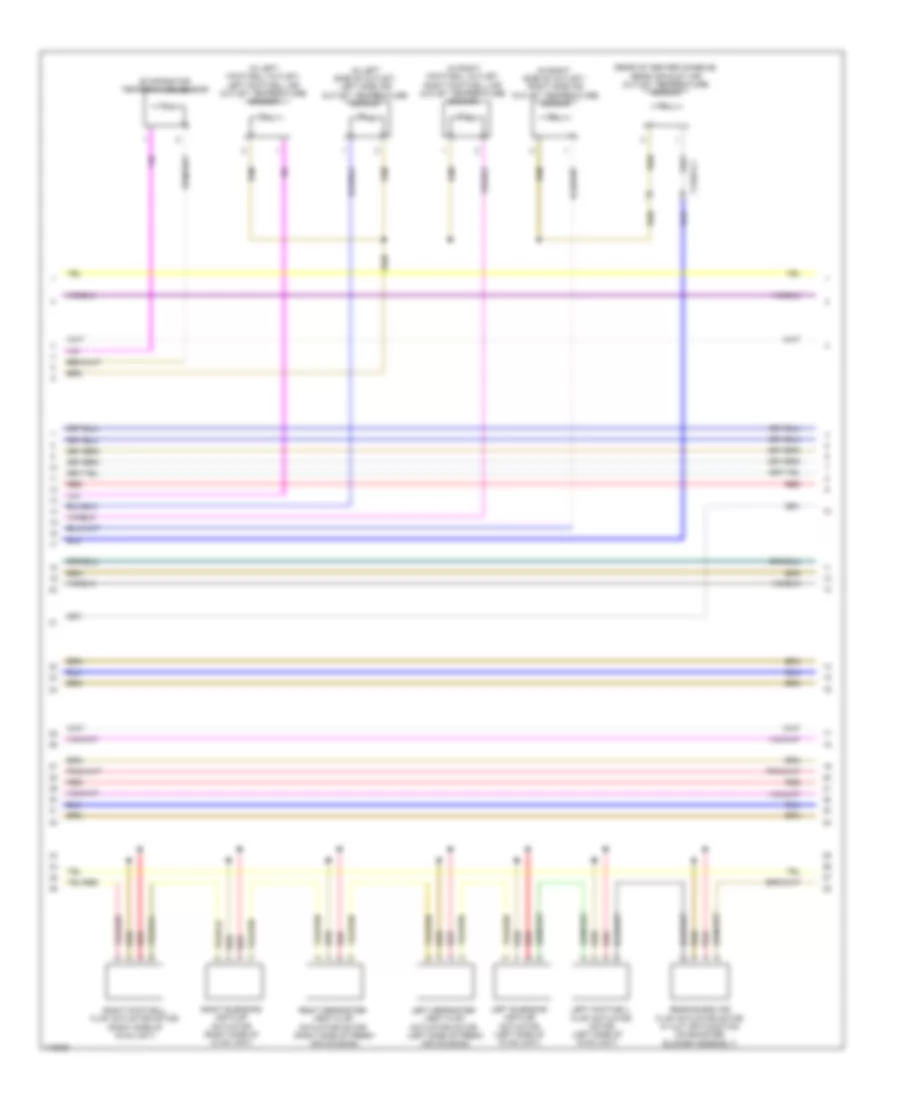
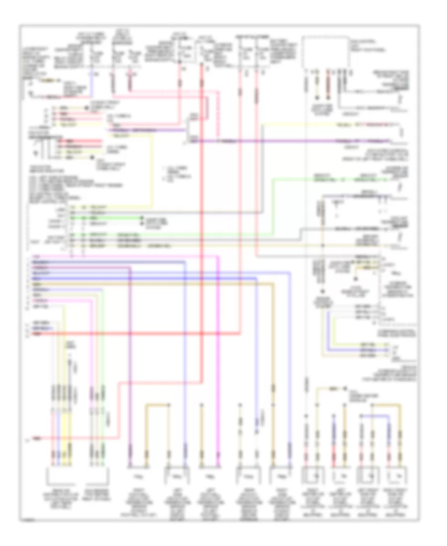
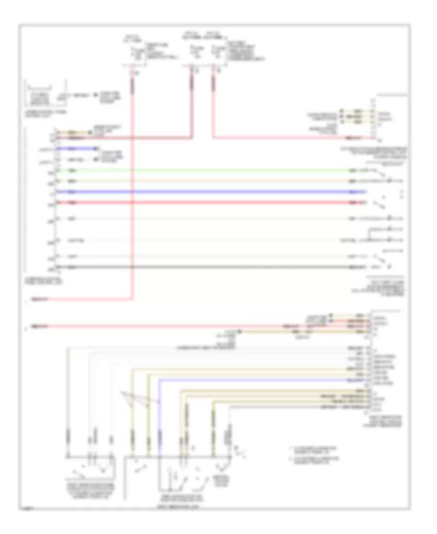
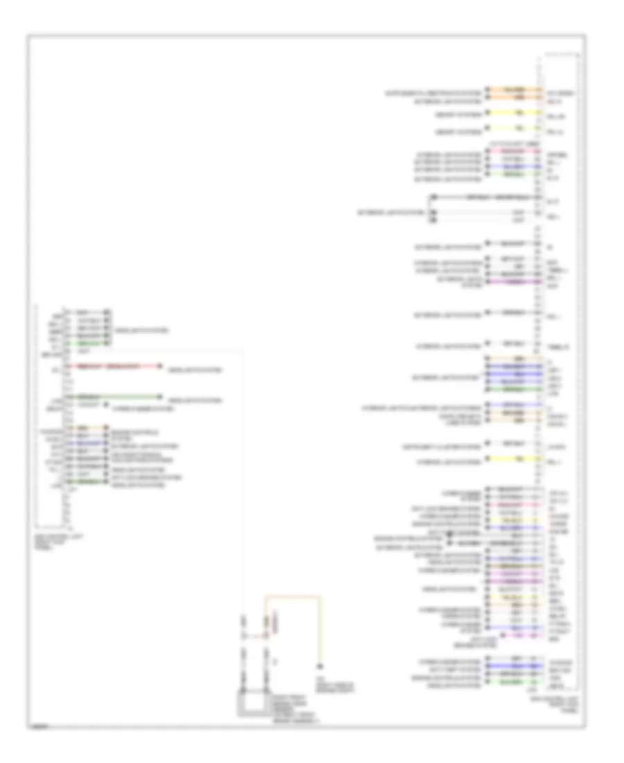
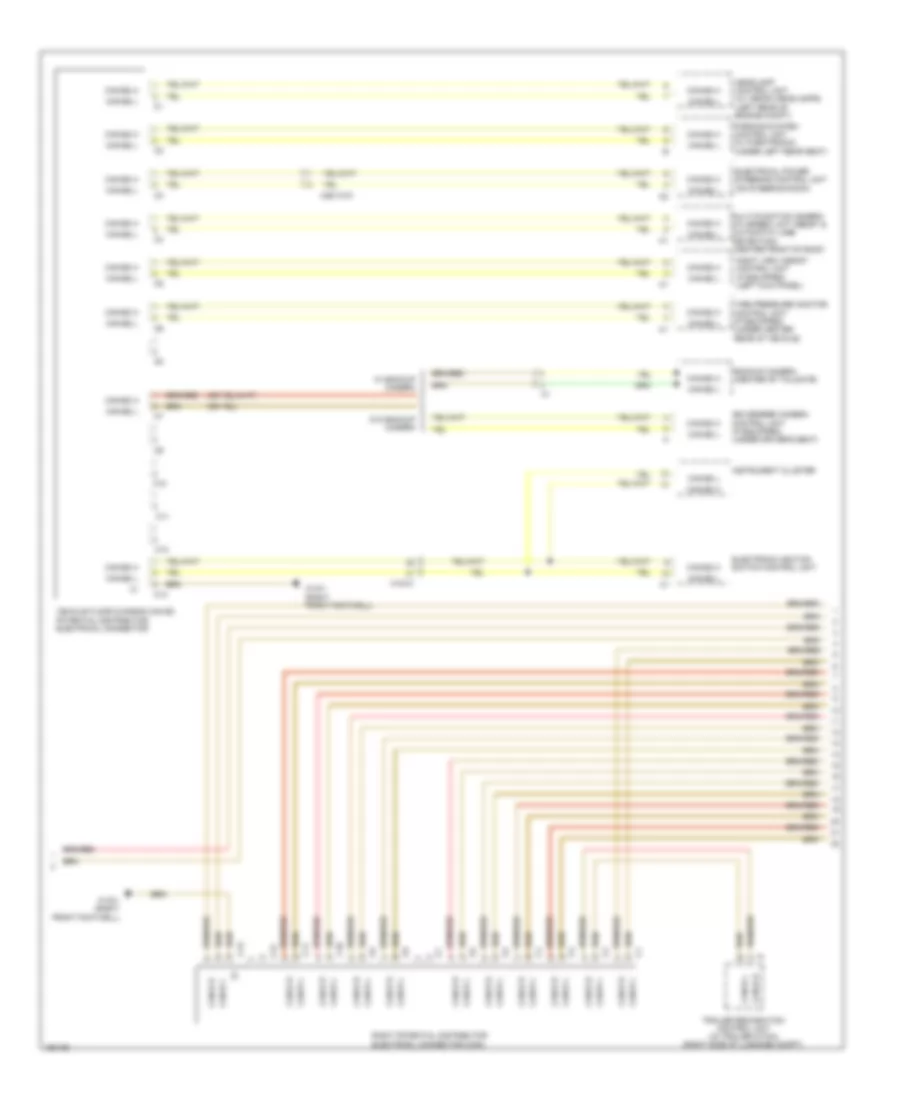
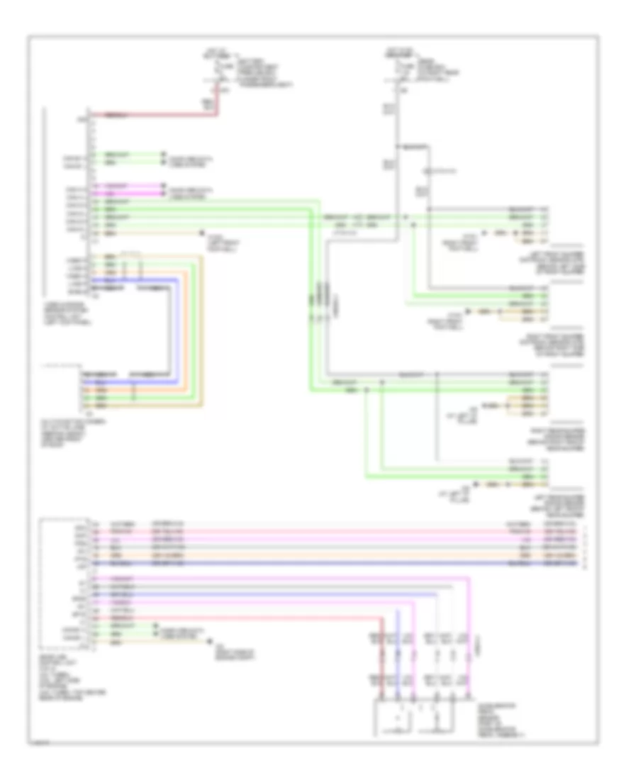
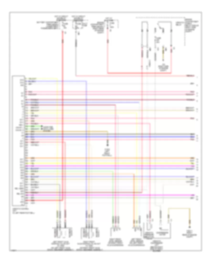
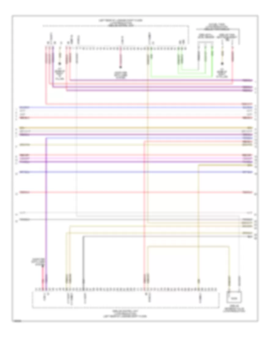
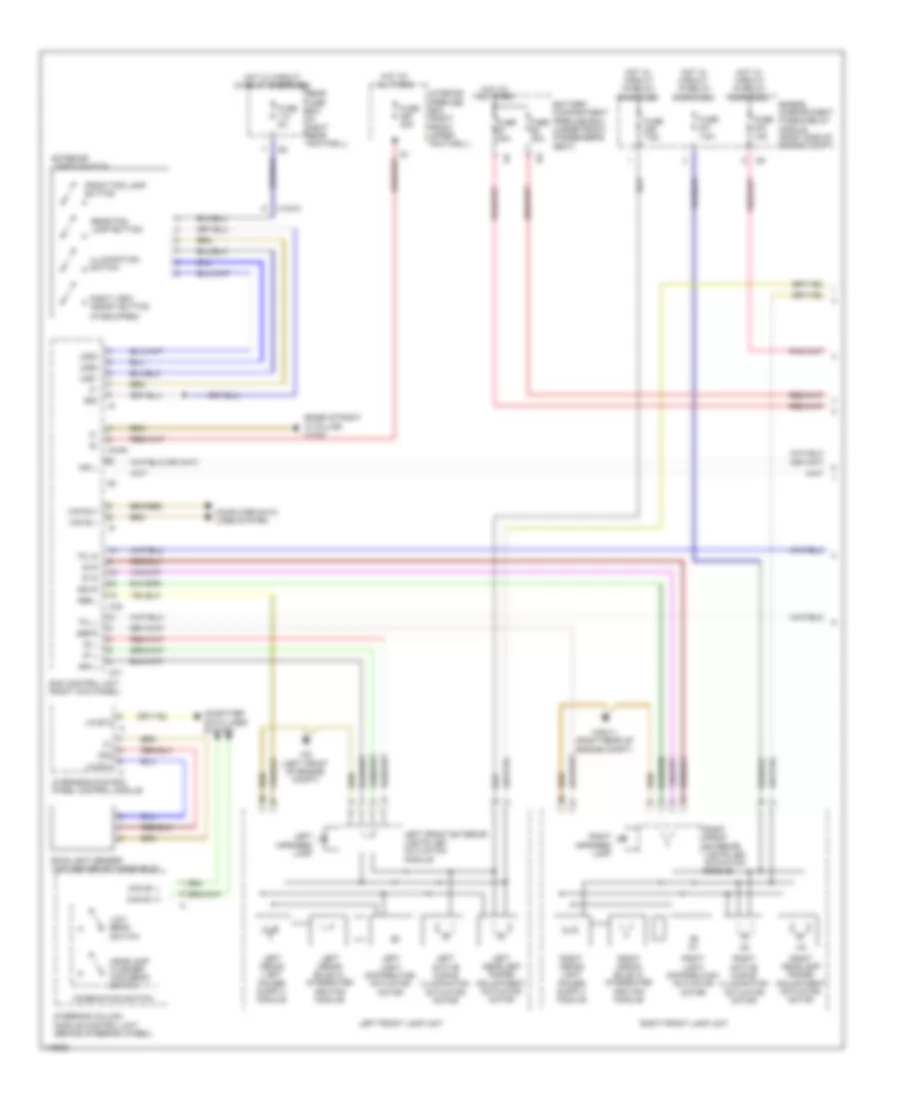
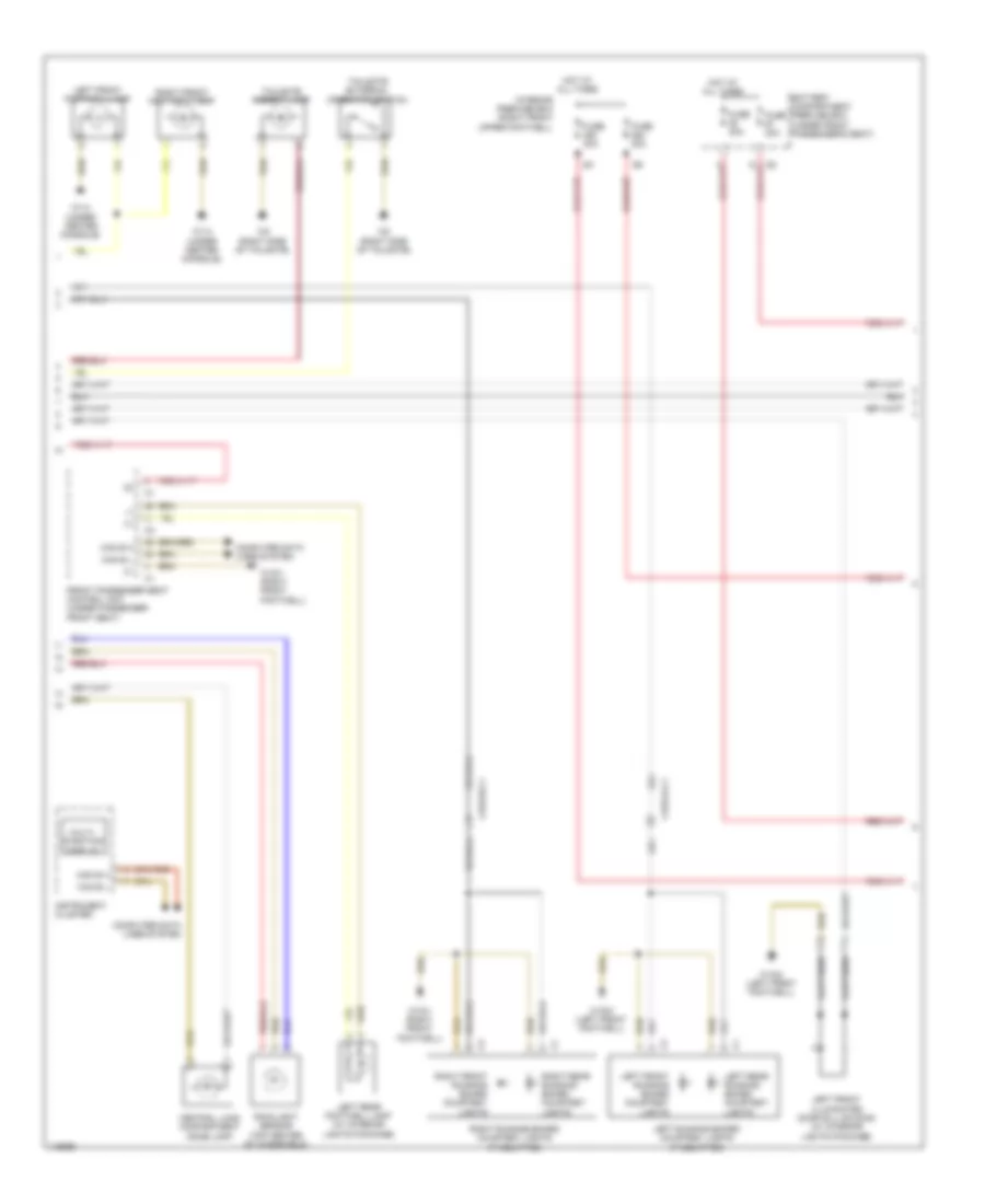
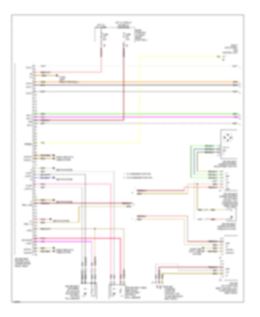
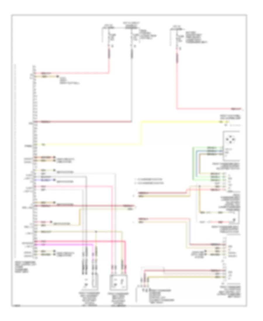
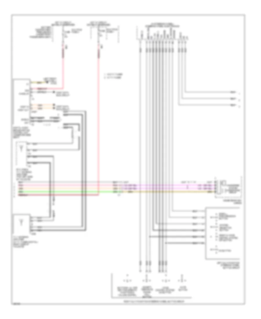
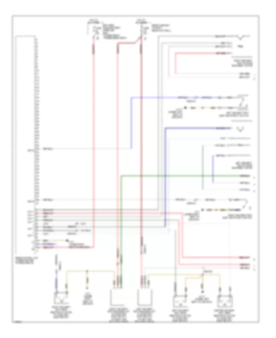
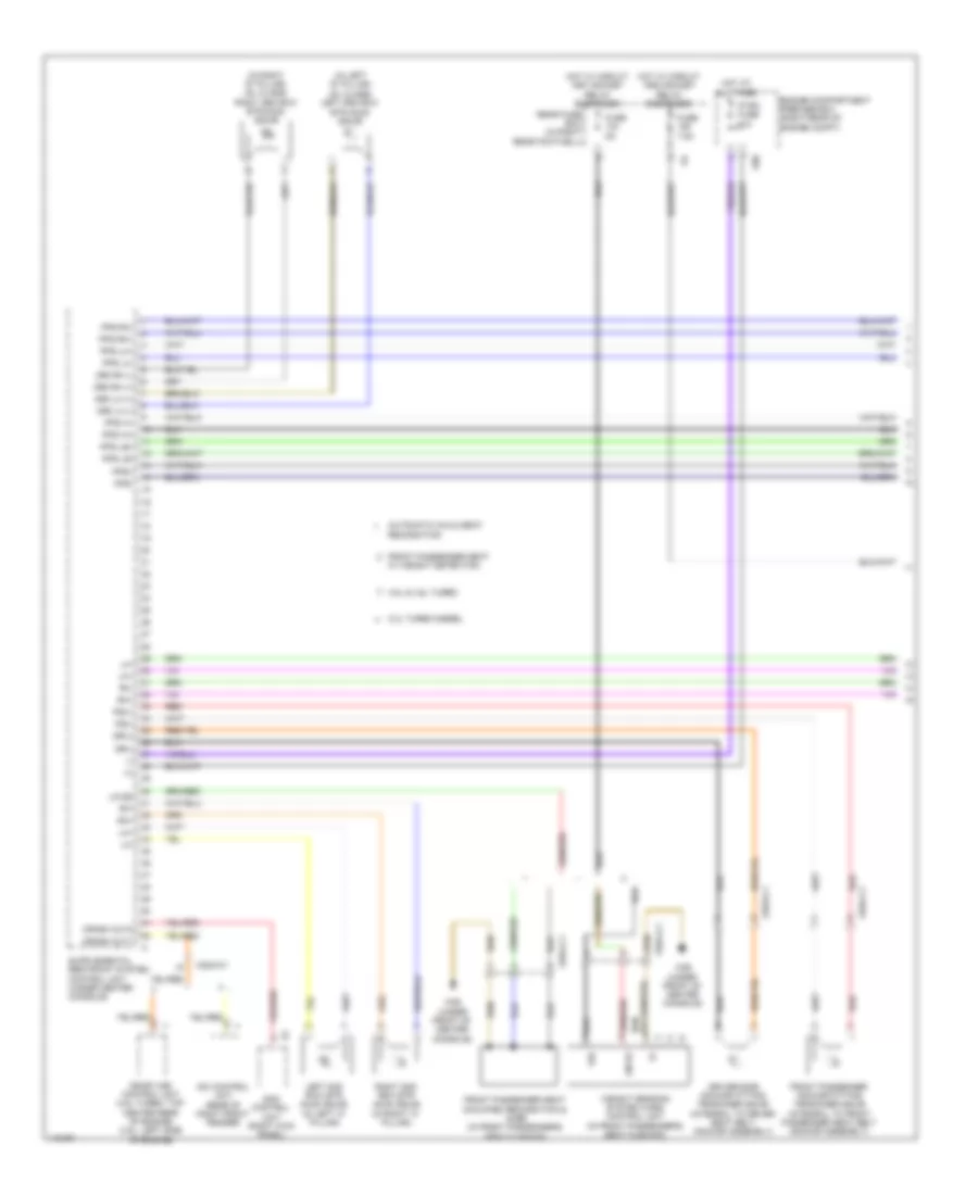
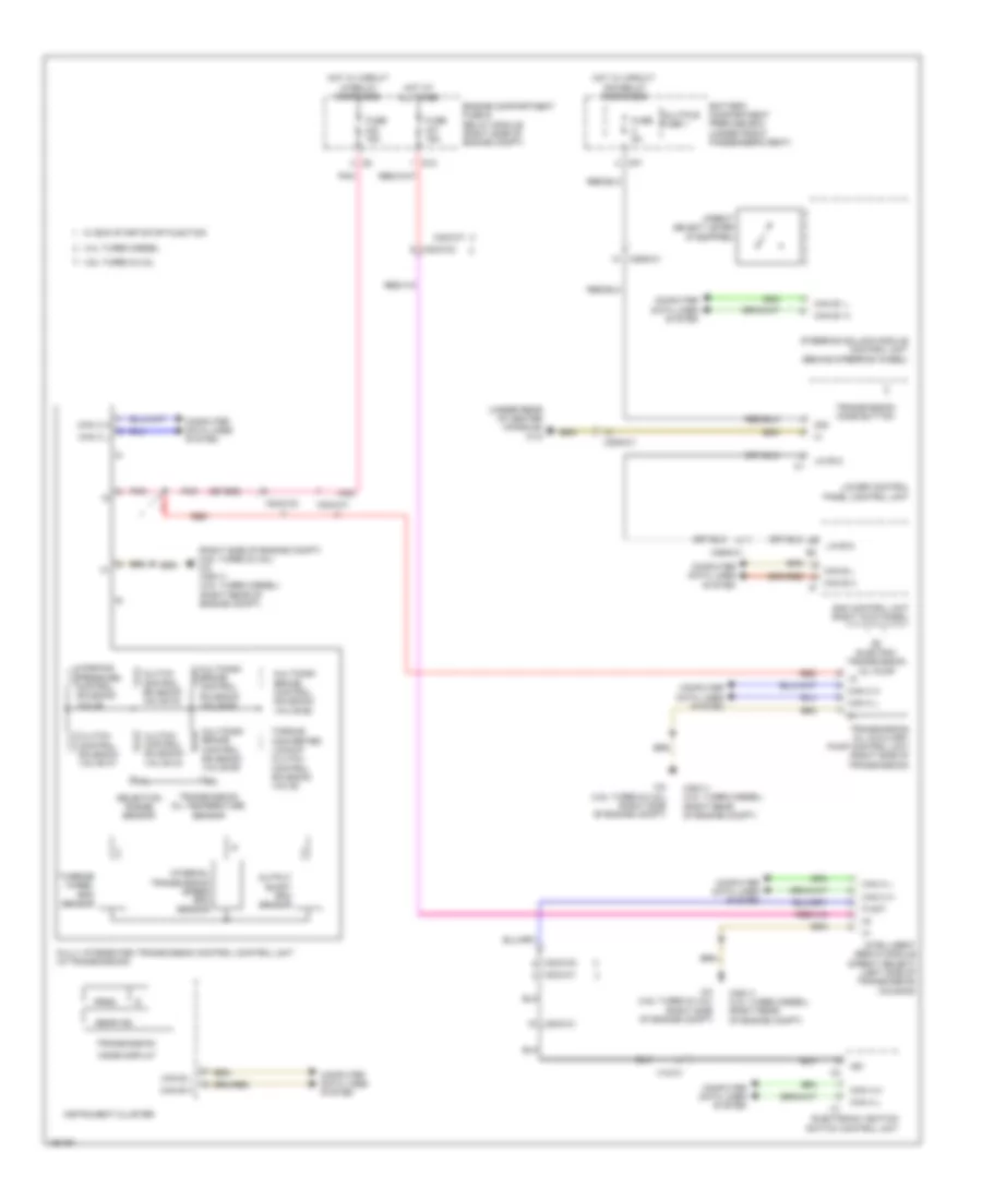
Automatic A/C Wiring Diagram, with Thermotronic (1 of 4) for Mercedes-Benz ML350 2014
 https://portal-diagnostov.com/license.html
Automotive Electricians Portal FZCO
Automotive Electricians Portal FZCO
https://portal-diagnostov.com/license.html
https://portal-diagnostov.com/license.html
Automotive Electricians Portal FZCO
Automotive Electricians Portal FZCO
List of elements for Automatic A/C Wiring Diagram, with Thermotronic (1 of 4) for Mercedes-Benz ML350 2014:
- (-)
- (info not available)
- (under center console) w1/4
- 30g
- Air recirculation mode button
- Automatic air conditioning control & operating unit
- Battery compartment prefuse box (under front passenger's seat)
- Booster blower electronic blower controller (on booster blower motor)
- C13a
- C19a
- Can b h
- Can b l
- Cbr bg
- Cockpit circuit 30 fuse box (behind right end of dash)
- Cockpit circuit 30g fuse box (behind right end of dash)
- Computer data lines system
- Coolant circulation pump (lower left front of engine compt)
- Defogger system
- Fresh air & air recirculation flap actuator motor (center rear of engine compt)
- Fuse 150a
- Fuse 15a
- Fuse 25a
- Fuse 40a
- Gnd
- High side
- Hot at all times
- Hot w/ circuit 30g relay energized
- Interior prefuse box (right front upper footwell)
- Kmv sk (+)
- Kmv sk (-)
- Komp pwr
- Komp rv(-)
- Lin
- Lin b8 (+)
- Lin b8 data
- Lin b8 gnd
- Lin b8 rf
- Lin data
- Nca
- Rear air conditioning electronic blower controller (if equipped) (on rear blower motor)
- Rear blower motor (under rear of center console)
- Red
- S14
- S22
- Sig
- Sig li
- Sig re
- Temp kr sig
- Temp v sig
- Vdf
- Vent v
- W1/4 (under center console)
- W6 (at left "d" pillar)
- W9 (left front of engine compt)
- Wahzg
- Wake up
- X122/2-c2
- X122/3-c1
- X18-c1
- X25/2-c1
- X26/4-c1
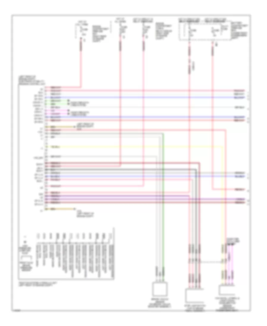
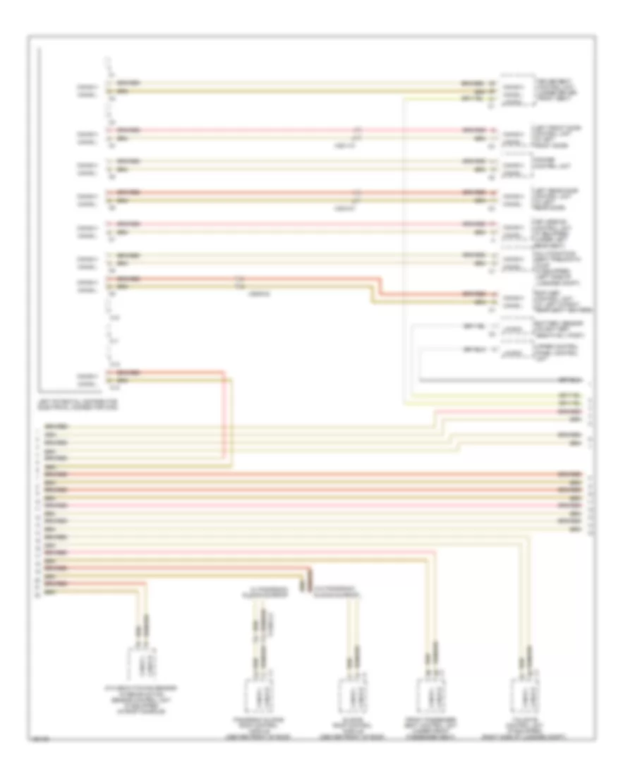
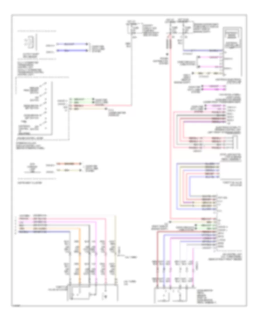
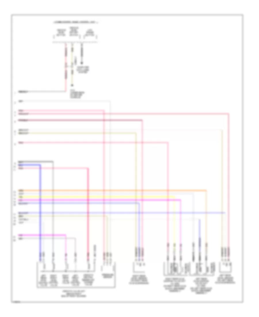
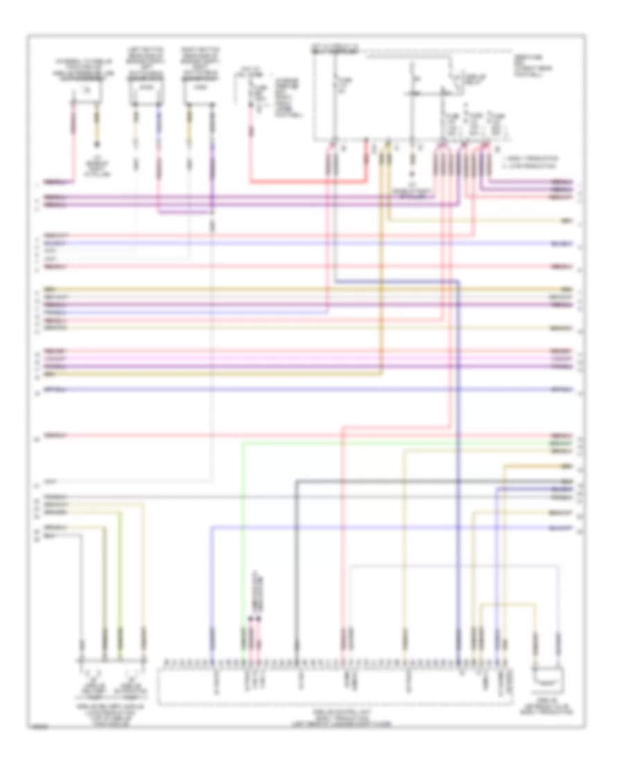
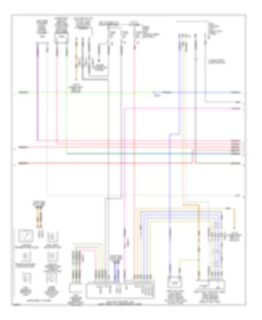
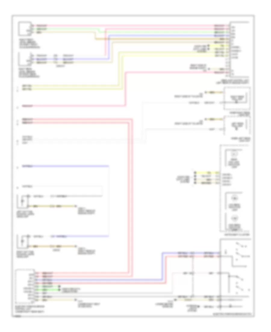
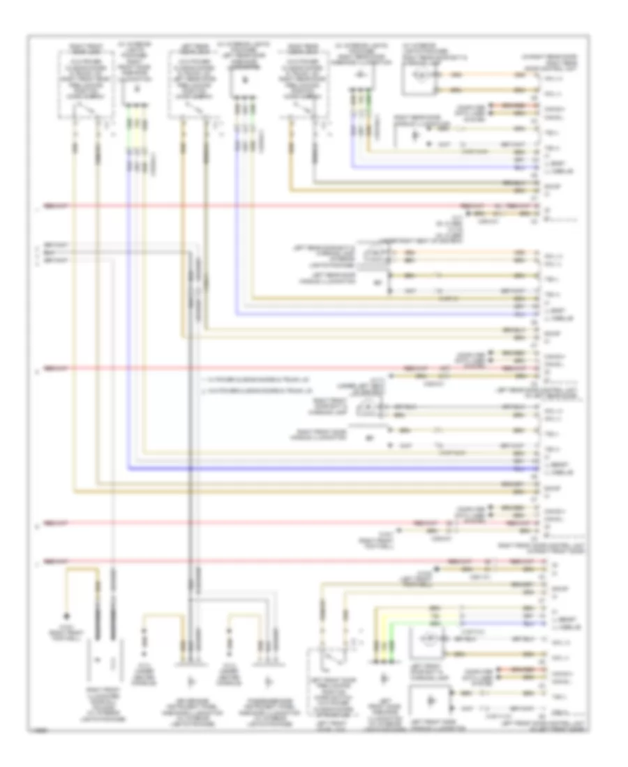
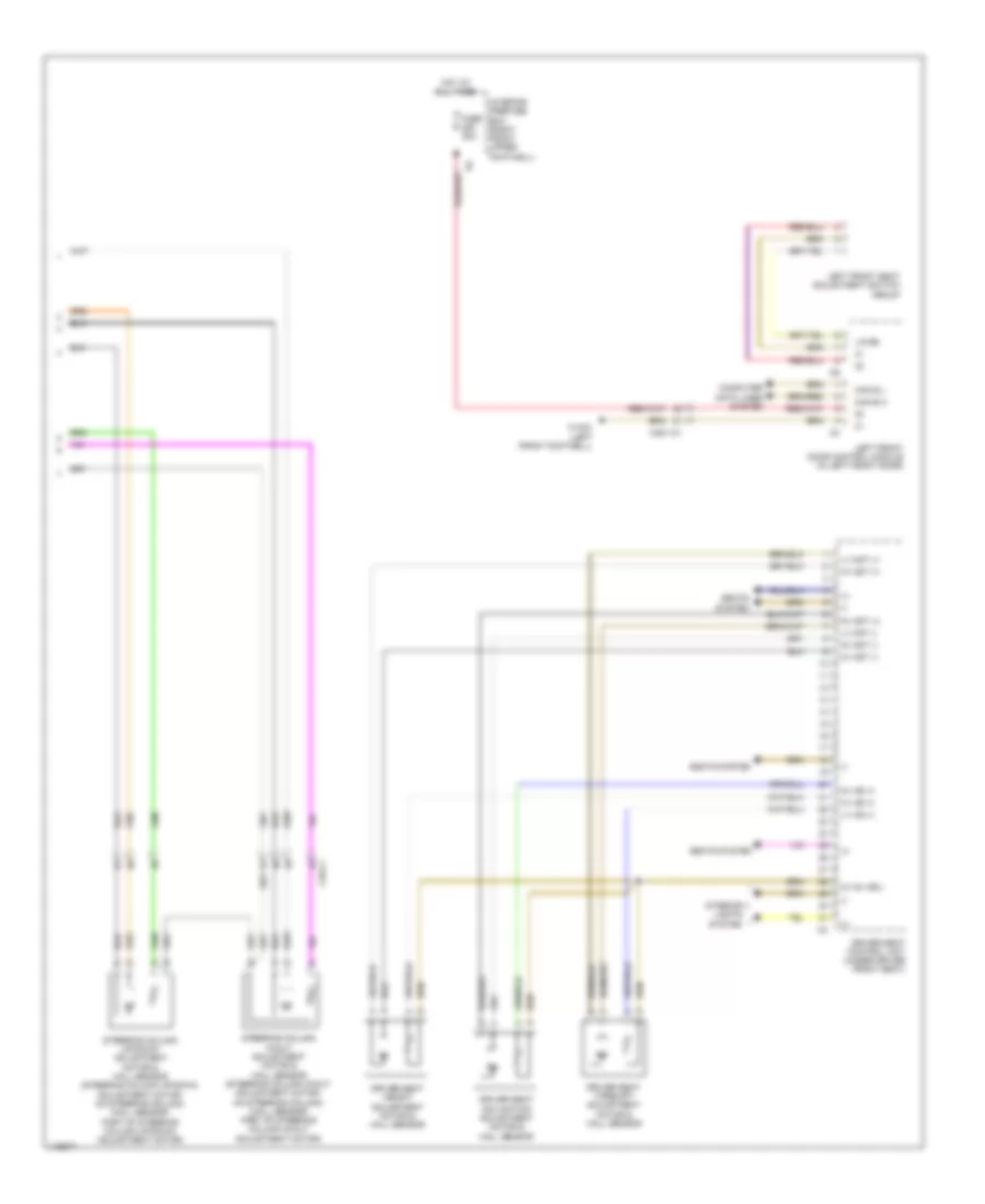
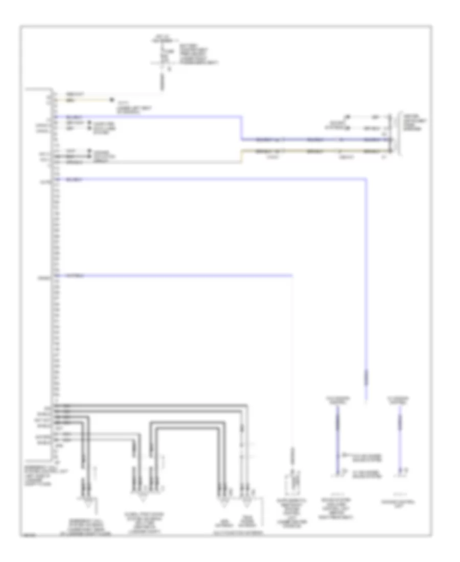
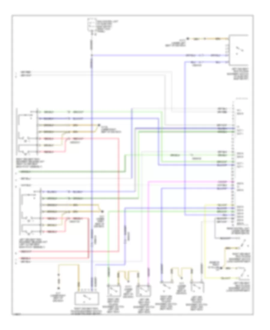
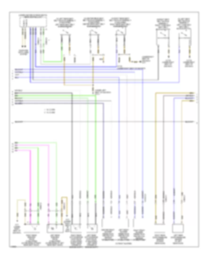
Automatic A/C Wiring Diagram, with Thermotronic (2 of 4) for Mercedes-Benz ML350 2014
List of elements for Automatic A/C Wiring Diagram, with Thermotronic (2 of 4) for Mercedes-Benz ML350 2014:
- (in left footwell outlet) left footwell air outlet temperature sensor
- (in left side of outlet) left side air outlet temperature sensor
- (in right footwell outlet) right footwell air outlet temperature sensor
- (in right side of outlet) right side air outlet temperature sensor
- (left side of hvac unit)
- (rear of center console) rear air duct air outlet temperature sensor
- Evaporator temperature sensor
- Left blending air flap actuator (left side of hvac unit)
- Left defroster vent flap actuator motor (left side of fresh air housing)
- Left footwell flap actuator motor
- Rear blend air flap actuator motor w/ cut off function (on booster blower assembly)
- Red
- Right blending air flap actuator (right side of hvac unit)
- Right defroster vent flap actuator motor (right side of fresh air housing)
- Right footwell flap actuator motor (right side of hvac unit)
- X122/2-c1
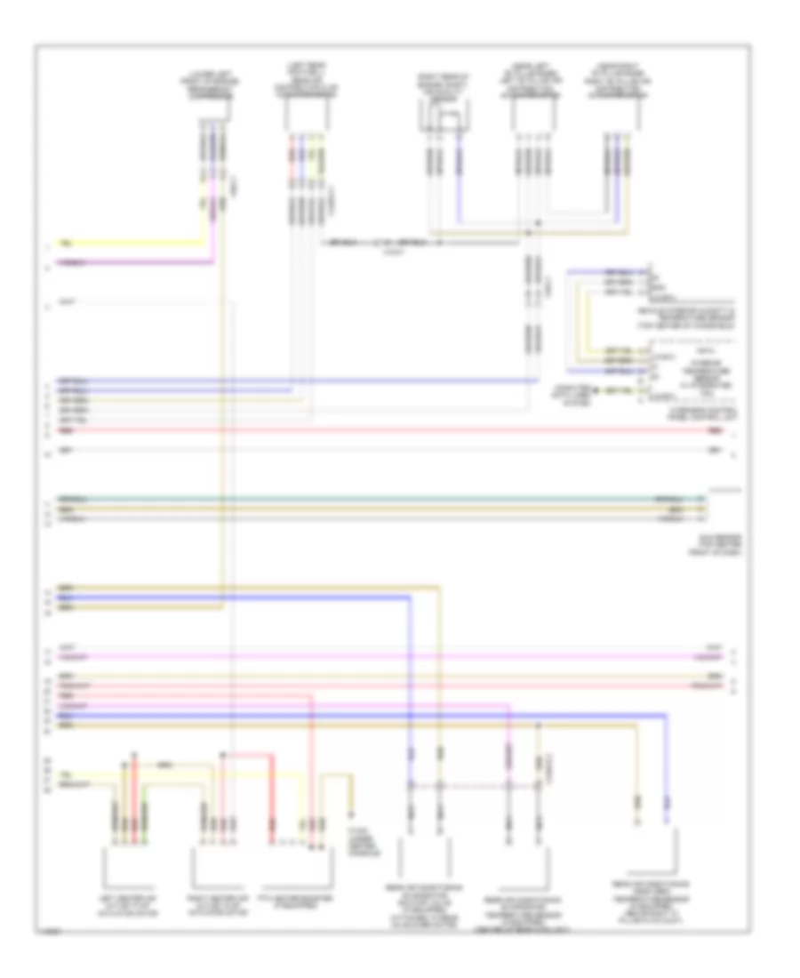
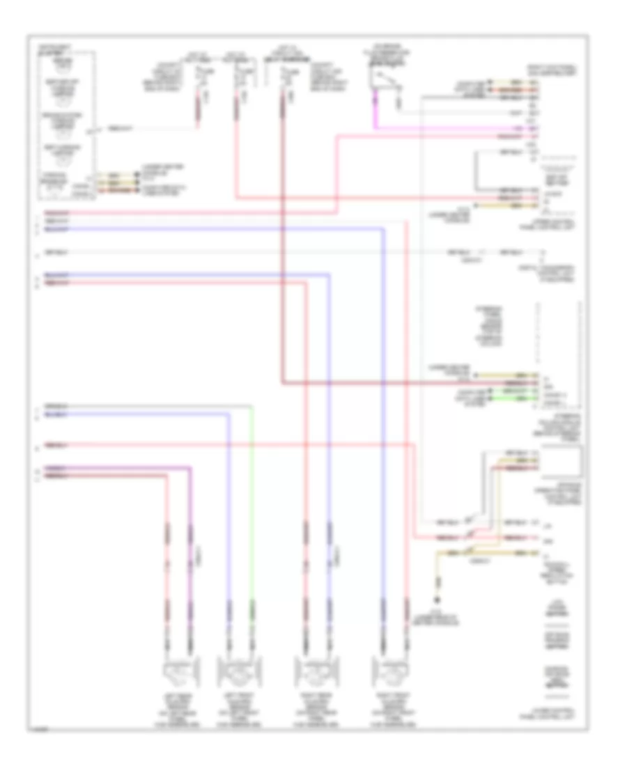
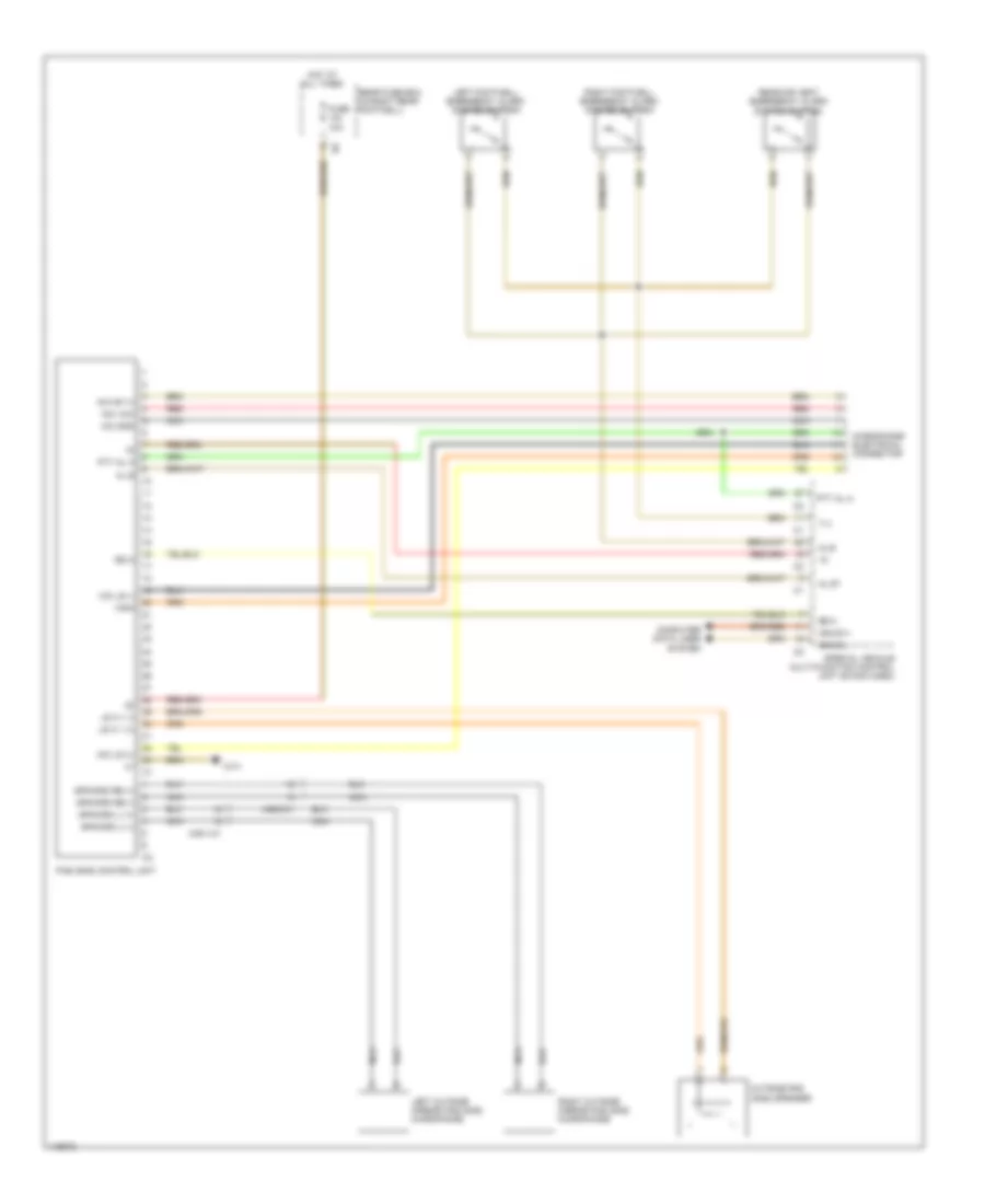
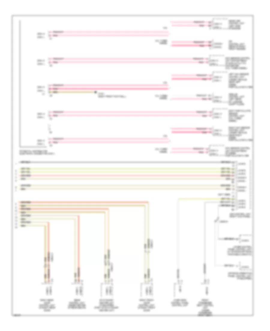
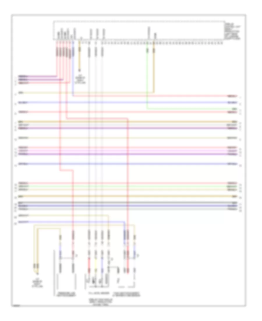
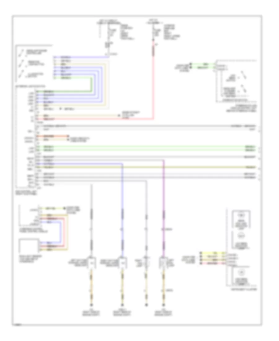
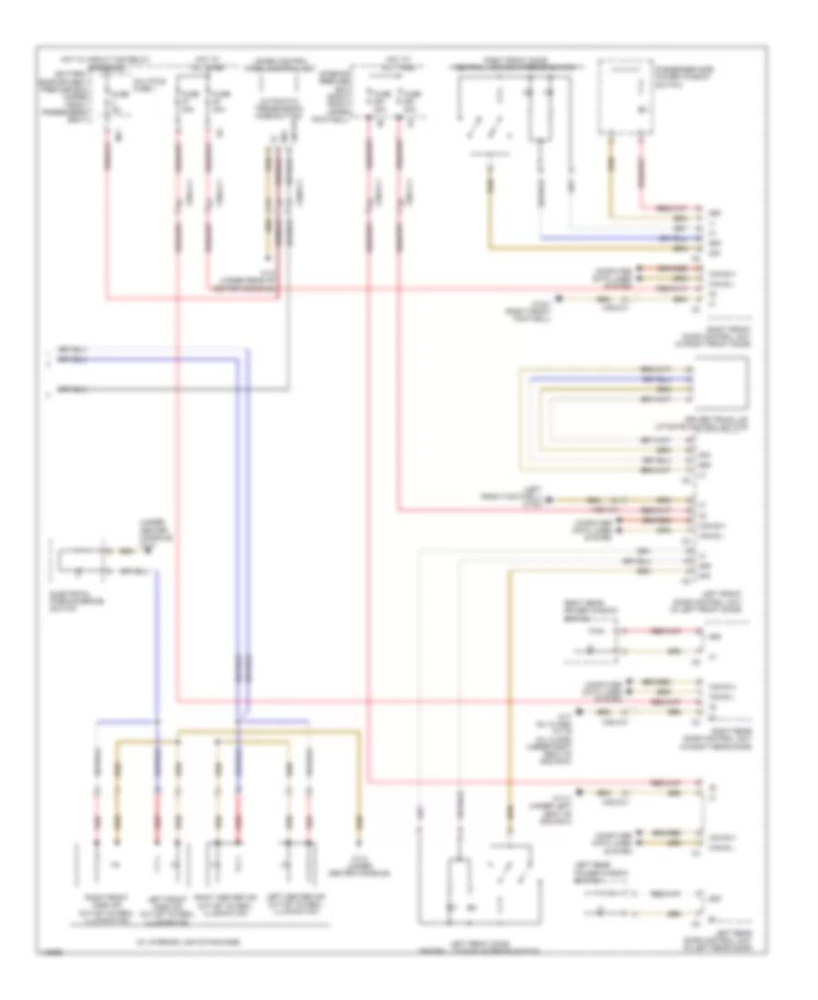
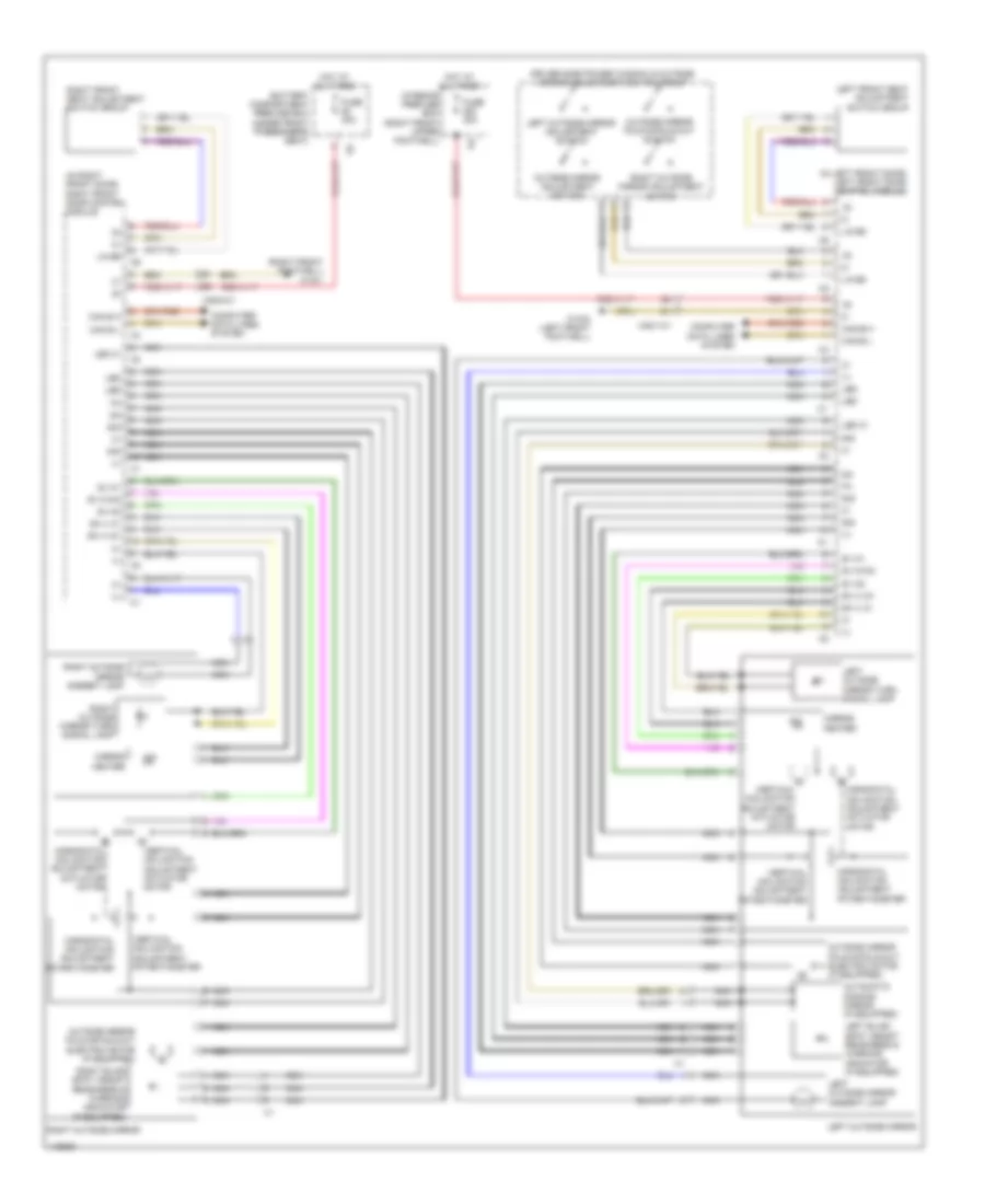
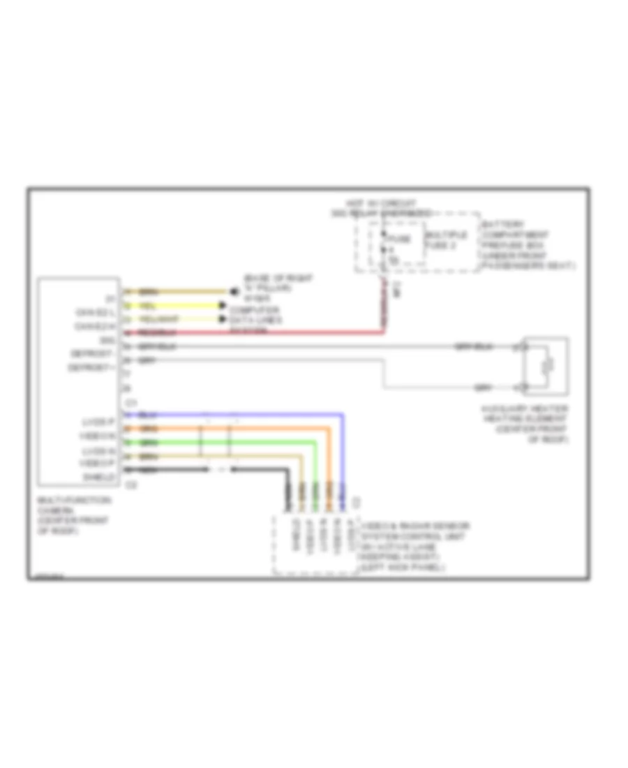
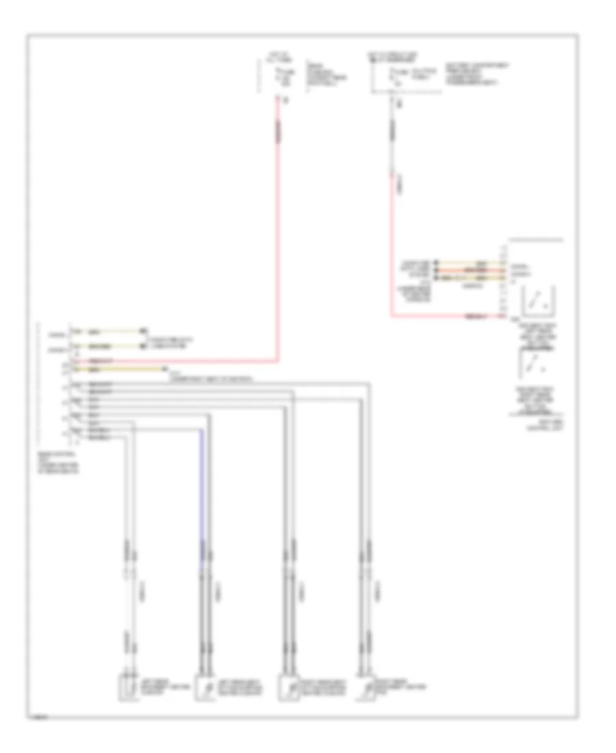
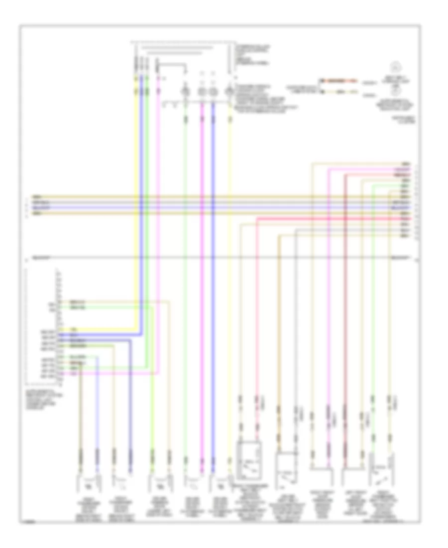
Automatic A/C Wiring Diagram, with Thermotronic (3 of 4) for Mercedes-Benz ML350 2014
List of elements for Automatic A/C Wiring Diagram, with Thermotronic (3 of 4) for Mercedes-Benz ML350 2014:
- (left rear footwell) rear air distribution flap actuator motor
- (lower left front of engine) refrigerant compressor
- (near left "b" pillar base) left "b" pillar air distribution actuator motor
- (near right "b" pillar base) right "b" pillar air distribution actuator motor
- (right rear of engine compt) air quality sensor
- Computer data lines system
- Gnd
- Interior temperature sensor w/ integrated fan
- Left center air outlet flap actuator motor
- Lin b13
- Nca
- Overhead control panel control unit
- Ptc heater booster (if equipped)
- Rear air conditioning evaporator shutoff valve (if equipped) (attached to rear a/c blower motor)
- Rear air conditioning evaporator temperature sensor (if equipped) (center of rear hvac unit)
- Rear air conditioning head area temperature sensor (if equipped) (above right "c" pillar in a/c duct)
- Red
- Right center air outlet flap actuator motor
- Sun sensor (top center front of dash)
- Vehicle interior humidity & temperature sensor (top center of windshield)
- W15/9 (under center console)
- X122/2-c1
- X122/3-c2
- X18-c1
- X26-c1
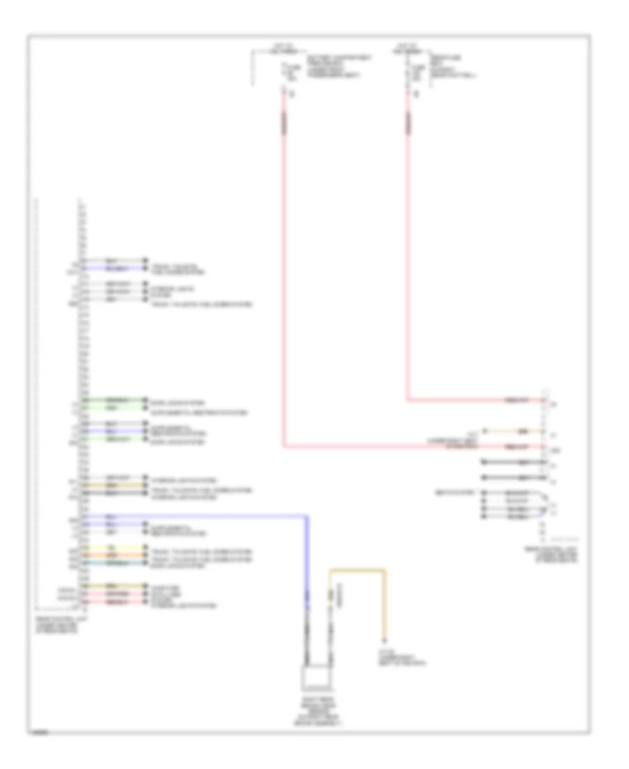
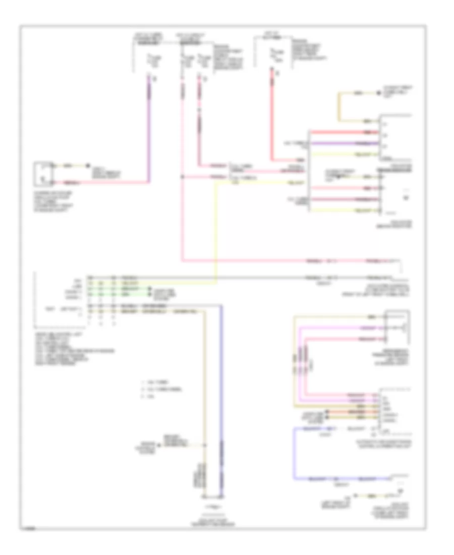
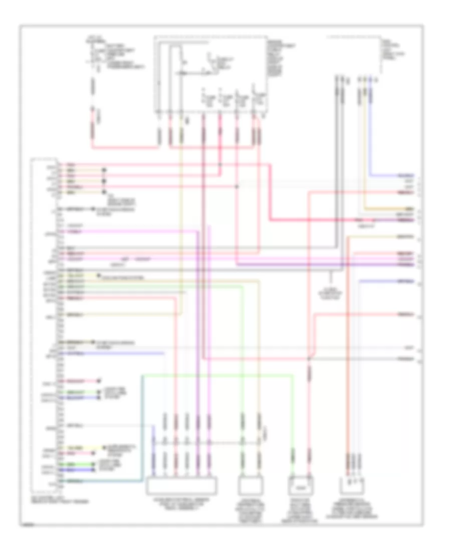
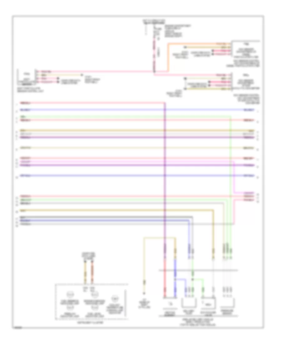
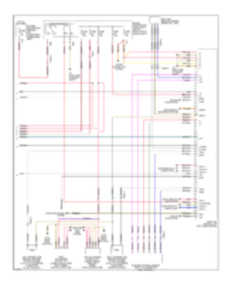
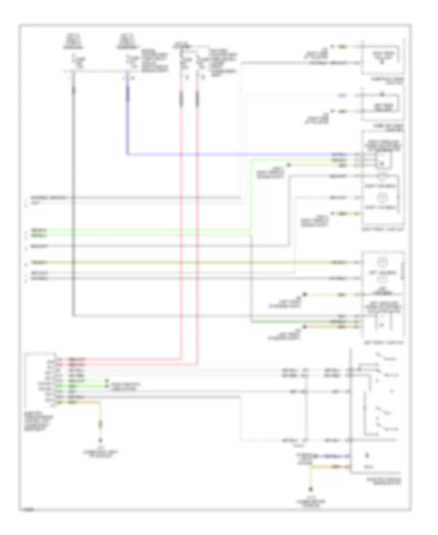
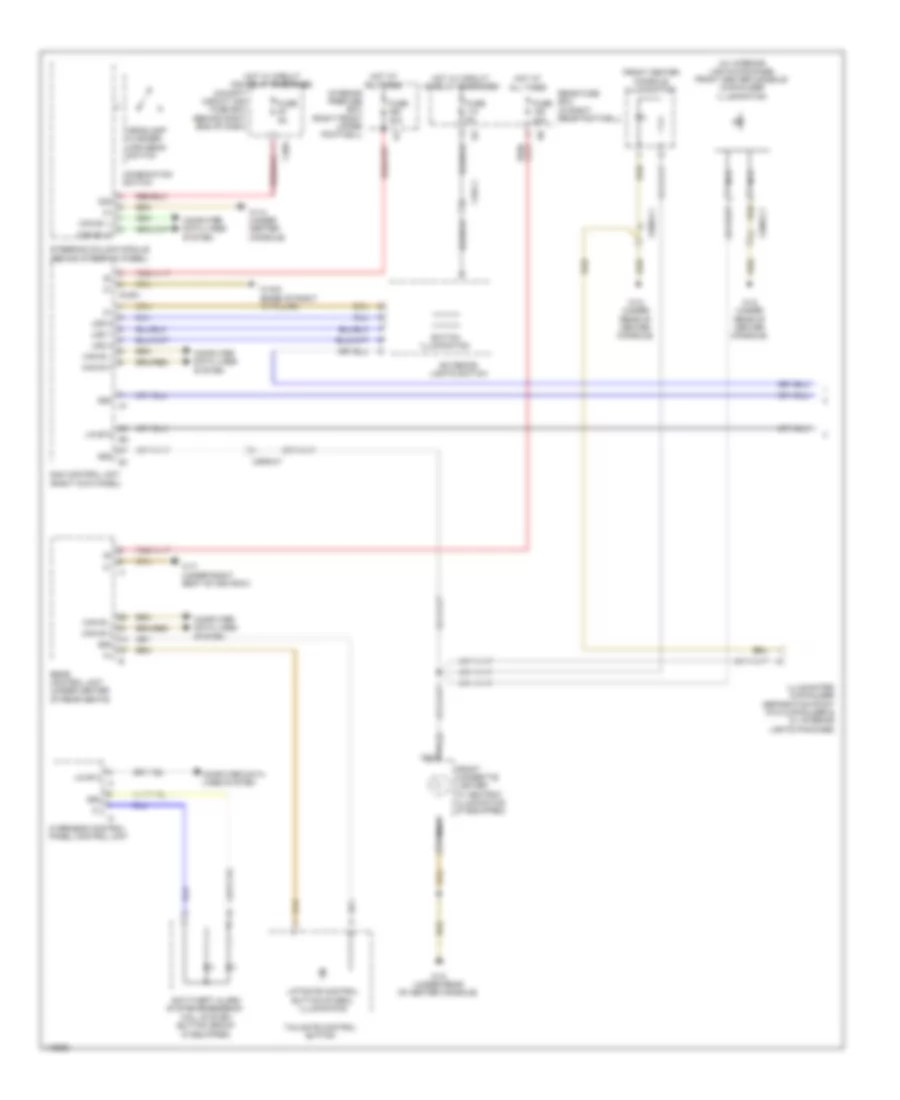
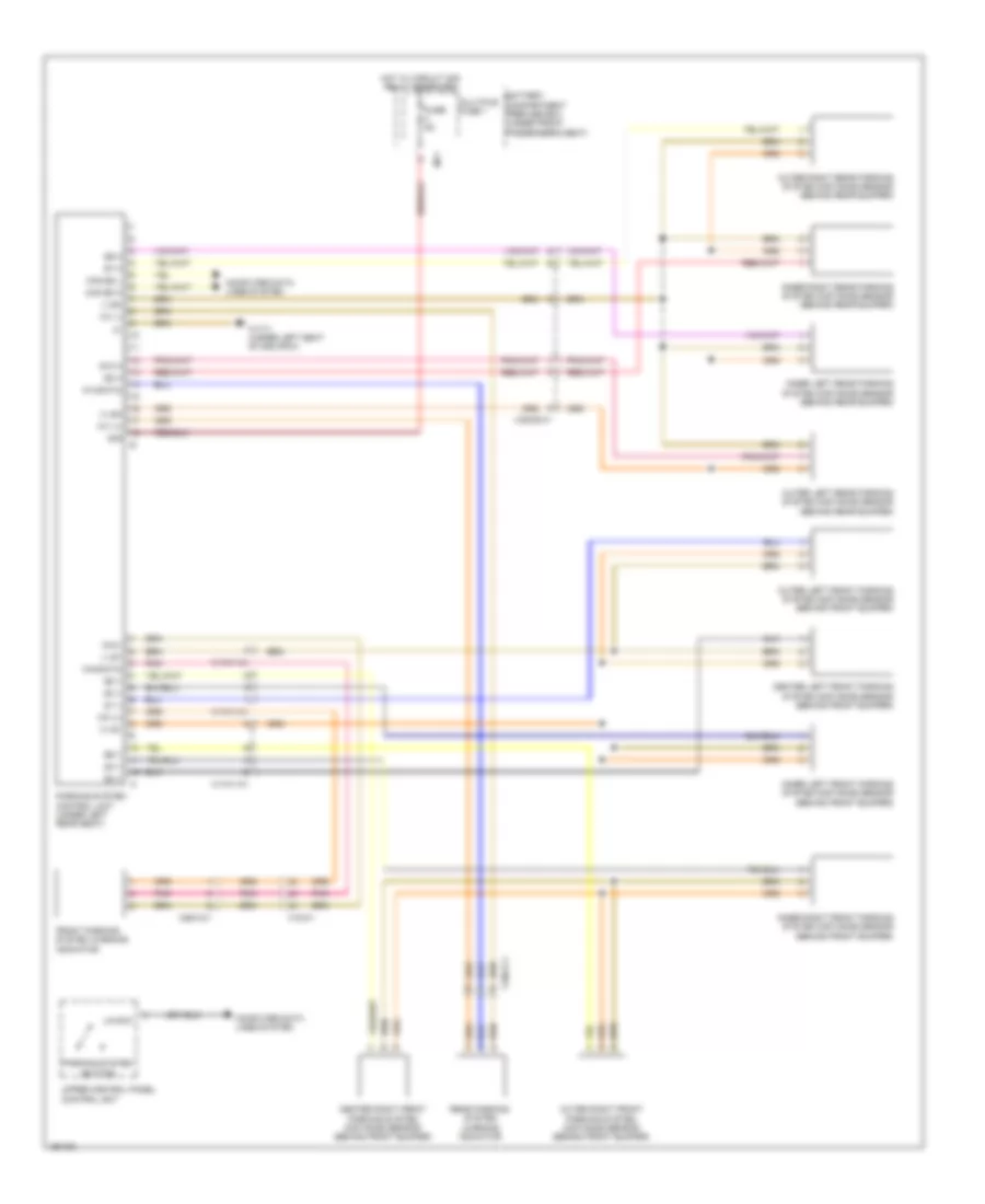
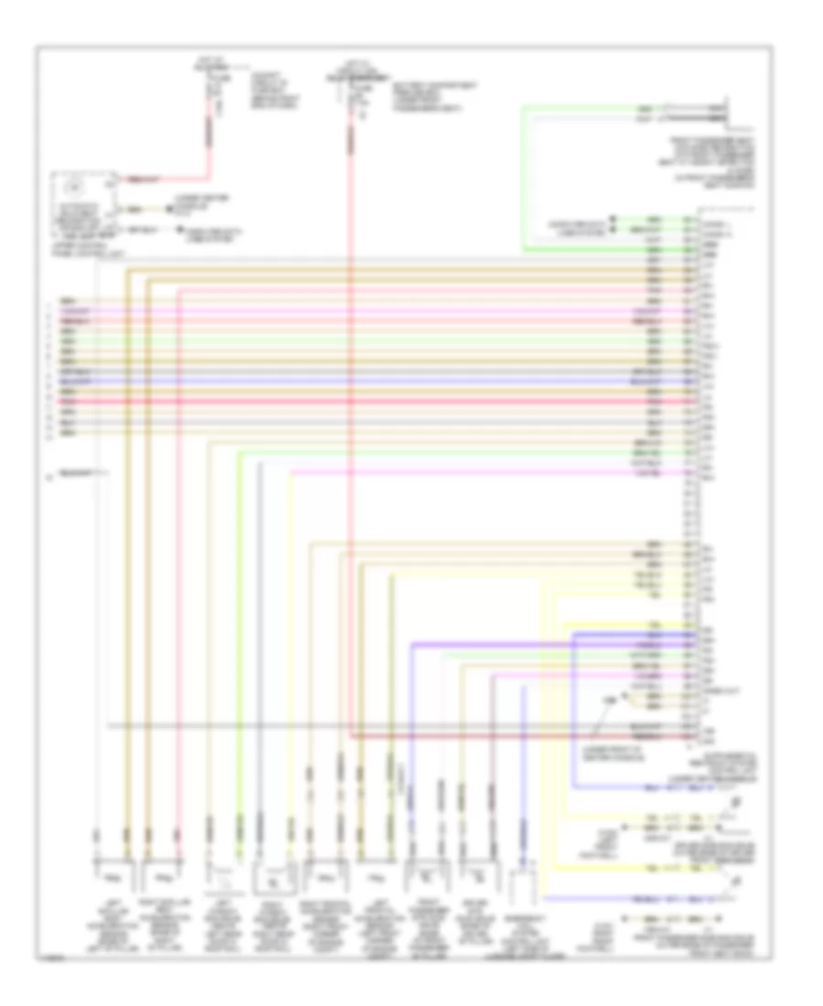
Automatic A/C Wiring Diagram, with Thermotronic (4 of 4) for Mercedes-Benz ML350 2014
List of elements for Automatic A/C Wiring Diagram, with Thermotronic (4 of 4) for Mercedes-Benz ML350 2014:
- (-)
- (4.6l turbo: top center rear of engine) (3.5l: left side of engine) (3.0l turbo diesel: rear of right front fender) (3.0l turbo diesel) cdi control module (4.6l turbo & 3.5l) me-sfi control unit
- (behind right side of front grille) outside temperature sensor
- (right kick panel) sam control unit
- 3.0l turbo diesel
- 3.5l
- 4.6l turbo
- 4.6l turbo & 3.5l
- Aav
- Ac housing
- Activated charcoal filter shutoff valve (front of left front wheelwell)
- Blower motor
- Blower regulator
- Can-e1 h
- Can-e1 l
- Charge air cooler circulation pump (4.6l turbo) (lower right front of engine compt)
- Charge air temperature sensor
- Computer data lines system
- Coolant temperature sensor
- Ea-tans
- Engine compartment fuse/relay module (right side of engine compt)
- Engine compartment prefuse box (right rear of engine compt)
- Engine controls system
- Fan motor (behind radiator)
- Fuse 10a
- Fuse 125a
- Fuse 15a
- Fuse 20a
- Hot at all times
- Hot w/ circuit 87m relay energized
- Hot w/ turbo charger relay energized
- Left center air outlet symbol illumination (if equipped)
- Left front side air outlet symbol illumination (if equipped)
- Lues
- Mr1
- Nca
- Pwm
- Red
- Refrigerant pressure sensor (left front of engine compt)
- Right center air outlet symbol illumination (if equipped)
- Right front side air outlet symbol illumination (if equipped)
- Tmot
- Uhi
- W1/4 (under center console)
- W2 (right side of engine compt)
- W2/1 (in right front wheelwell)
- W52/11 (right rear of engine compt)
- W9 (left front of engine compt)
- Wiper park heater
- Wiper park position heater relay
- X25/2-c1
- X26-c3
- X26/32-c1
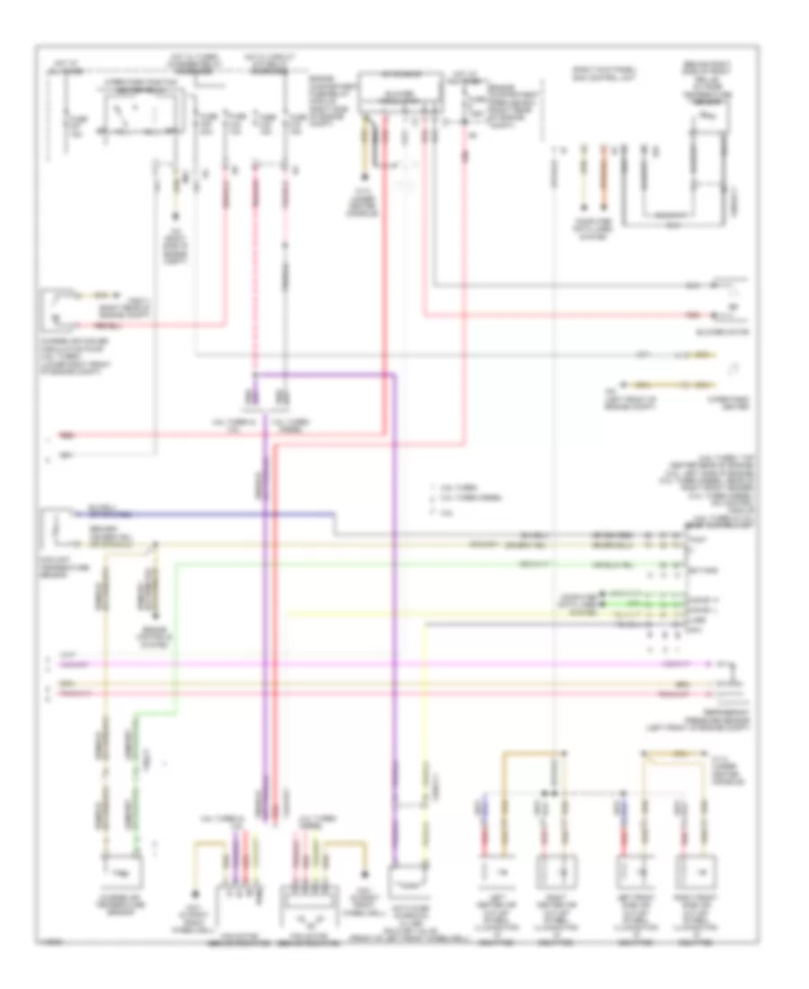
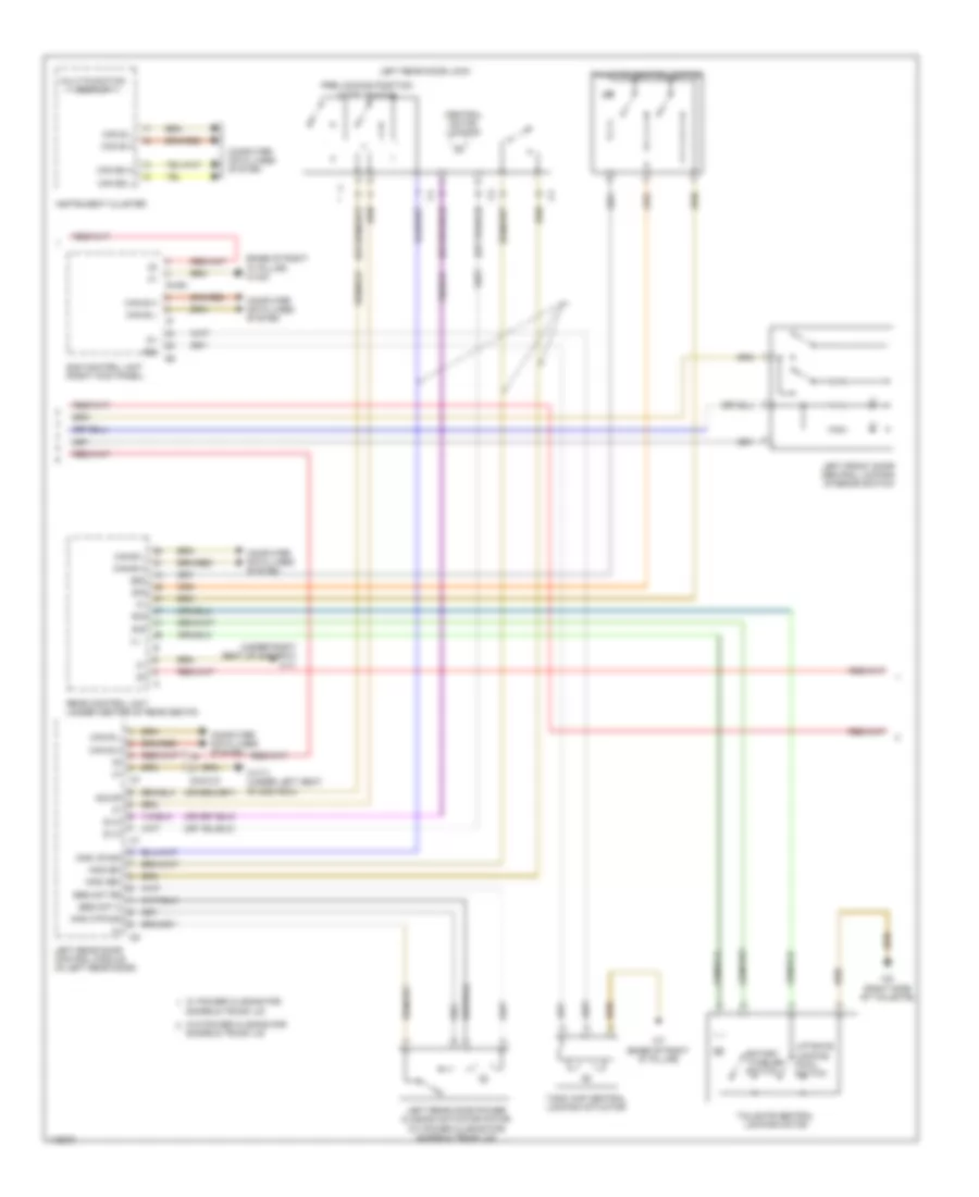
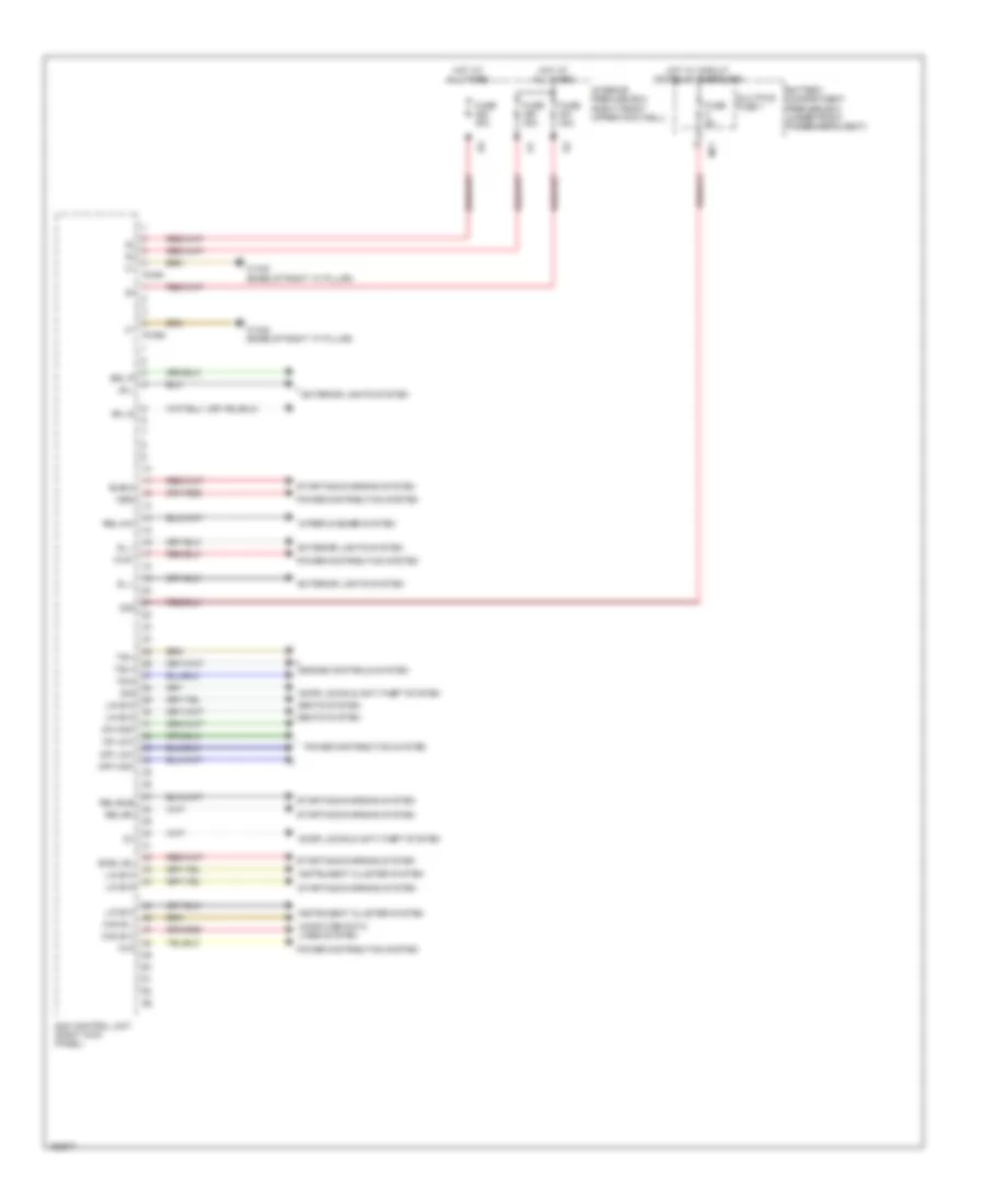
Automatic A/C Wiring Diagram, without Thermotronic (1 of 2) for Mercedes-Benz ML350 2014
List of elements for Automatic A/C Wiring Diagram, without Thermotronic (1 of 2) for Mercedes-Benz ML350 2014:
- (-)
- (5 to 7 pins not used)
- (9 & 10 pins not used)
- (left front side of engine compt) w9
- (under center console) w1/4
- 30g
- A/c housing
- Air recirculation mode button
- Automatic air conditioning control & operating unit
- Blower motor
- Blower regulator
- C19a
- Can-b h
- Can-b l
- Cockpit circuit 30g fuse box (behind right end of dash)
- Computer data lines system
- Coolant circulation pump (lower left front of engine compt)
- Defogger system
- Engine compartment fuse & relay module (right side of engine compt)
- Evaporator temperature sensor
- Fresh air/ air recirculation flap actuator motor (center rear of engine compt)
- Fuse 15a
- Fuse 20a
- Gnd
- High side
- Hot at all times
- Kmv sk (+)
- Komp pwr
- Komp rv (-)
- Left blending air flap actuator motor (left side of hvac unit)
- Left center air outlet flap actuator motor
- Left defroster vent flap actuator motor (top left side of fresh air housing)
- Left footwell flap actuator motor (left side of hvac unit)
- Lin b8 (+)
- Lin b8 data
- Lin b8 gnd
- Lin b8 rf
- Lin data
- Mr1
- Nca
- Ptc heater booster (if equipped)
- Rear blend air flap actuator motor w/ cut off function (on booster blower assembly)
- Red
- Refrigerant compressor (3.5l) (lower left front of engine)
- Refrigerant pressure sensor (left front of engine compt)
- Right blending air flap actuator motor (right side of hvac unit)
- Sig
- Sig li
- Sig re
- Vdf
- W1/4 (under center console)
- W15/9 (under center console)
- W2 (right side of engine compt)
- W9 (left front of engine compt)
- Wah7g
- Wiper park heater
- Wiper park position heater relay
- X18-c1
- X18-c2
- X25/2-c1
- X26-c1
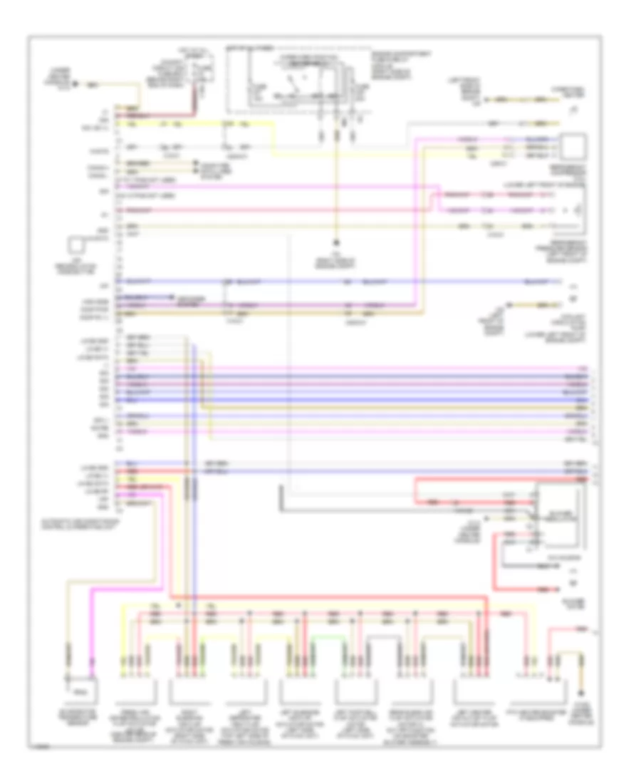
Automatic A/C Wiring Diagram, without Thermotronic (2 of 2) for Mercedes-Benz ML350 2014
List of elements for Automatic A/C Wiring Diagram, without Thermotronic (2 of 2) for Mercedes-Benz ML350 2014:
- (-)
- (4.6l: left side of engine) (3.5l: top center rear of engine) (3.0l turbo diesel: rear of right front fender) (3.0l turbo diesel) cdi control module (except 3.0l turbo diesel) me-sfi control unit
- (behind right side of front grille) outside temperature sensor
- (in right front wheelwell) w2/1
- (lower right front of engine compt) (4.6l turbo) charge air cooler circulation pump
- (not used)
- (or tmot 1)
- 3.0l turbo diesel
- 3.0l turbo diesel 4.6l turbo & 3.5l
- 4.6l turbo & 3.5l
- Aav
- Activated charcoal filter shutoff valve (front of left front wheelwell)
- Battery compartment prefuse box (under front passenger's seat)
- Can-e1 h
- Can-e1 l
- Charge air temperature sensor
- Computer data lines system
- Coolant temperature sensor
- Ea-tans
- Engine compartment fuse & relay module (right side of engine compt)
- Engine compartment prefuse box (right rear of engine compt)
- Engine controls system
- Fan motor (behind radiator)
- Fuse 10a
- Fuse 125a
- Fuse 150a
- Fuse 15a
- Fuse 40a
- Gnd
- Hot at all times
- Hot w/ circuit 87m relay energized
- Hot w/ turbo charger relay energized
- Interior prefuse box (right front footwell)
- Interior temperature sensor w/ integrated fan
- Left center air outlet symbol illumination (if equipped)
- Left footwell air outlet temperature sensor (in left footwell outlet)
- Left front side air outlet symbol illumination (if equipped)
- Left side air outlet temperature sensor (in left side of outlet)
- Lin
- Lin b13
- Lues
- Overhead control panel electronics
- Pwm
- Rear air distribution flap actuator motor (left rear footwell)
- Rear air duct air outlet temperature sensor (rear of center console)
- Red
- Right center air outlet symbol illumination (if equipped)
- Right footwell air outlet temperature sensor (in right footwell outlet)
- Right front side air outlet symbol illumination (if equipped)
- Right side air outlet temperature sensor (in right side of outlet)
- S14
- Sam control unit (right kick panel)
- Sun sensor (top center front of dash)
- Tmot
- Uhi
- Vehicle interior humidity & temperature sensor (top center of windshield)
- W1/4 (under center console)
- W18/5 (base of right "a" pillar)
- W2/1 (in right front wheelwell)
- W52/11 (right rear of engine compt)
- X122/2-c1
- X18-c1
- X25/2-c1
- X26-c3
- X26/32-c1
- X26/4-c1
ANTI-LOCK BRAKES
Anti-lock Brakes Wiring Diagram (1 of 2) for Mercedes-Benz ML350 2014
List of elements for Anti-lock Brakes Wiring Diagram (1 of 2) for Mercedes-Benz ML350 2014:
- (+)
- (-)
- (left front of engine compt) electronic stability program control unit
- (left front of engine compt) w70
- +12v
- 30g
- Ball valve front axle intake
- Ball valve rear axle intake
- Battery compartment prefuse box (under front passenger's seat)
- Bla
- Bls h
- Bls l
- Bls m
- Brake vacuum sensor (on brake vacuum booster assembly)
- Can e1 h
- Can e1 l
- Can-h h
- Can-h l
- Computer data lines system
- Df hl m
- Df hl s
- Df hr m
- Df hr s
- Df vl m
- Df vl s
- Df vr m
- Df vr s
- Dzvl a
- Engine compartment fuse & relay module (right side of engine compt)
- Engine compartment prefuse box (right rear of engine compt)
- Front axle brake pressure sensor
- Fuse 25a
- Fuse 40a
- Fuse 5a
- High pressure & return pump
- Hot at all times
- Hot w/ circuit 15 relay energized
- Hot w/ circuit 30g relay energized
- Mf1
- Multi- fuse
- Regulator valve (hold) left front pressure
- Regulator valve (hold) left rear pressure
- Regulator valve (hold) right front pressure
- Regulator valve (hold) right rear pressure
- Regulator valve (release) left front pressure
- Regulator valve (release) left rear pressure
- Regulator valve (release) right front pressure
- Regulator valve (release) right rear pressure
- Stop lamp switch (top of brake pedal assembly)
- Switchover valve front axle
- Switchover valve rear axle
- Traction system hydraulic unit (left front of engine compt)
- Ub (+)
- Vac_sig
- W70 (left front of engine compt)
- X25/2-c1
- X25/2-c2
- Yaw rate, lateral & longitudinal acceleration sensor (under front passenger's seat)
Anti-lock Brakes Wiring Diagram (2 of 2) for Mercedes-Benz ML350 2014
List of elements for Anti-lock Brakes Wiring Diagram (2 of 2) for Mercedes-Benz ML350 2014:
- (on brake fluid reservoir) brake fluid level switch
- (right kick panel) sam control unit
- (under center console) w1/4
- 30g
- Abs ind
- Brake system warning lamp ind
- C12a
- C15a
- C20a
- Can-b h
- Can-b l
- Can-e1 h
- Can-e1 l
- Cockpit circuit 30 fuse box (behind right end of dash)
- Cockpit circuit 30g fuse box (behind right end of dash)
- Computer data lines system
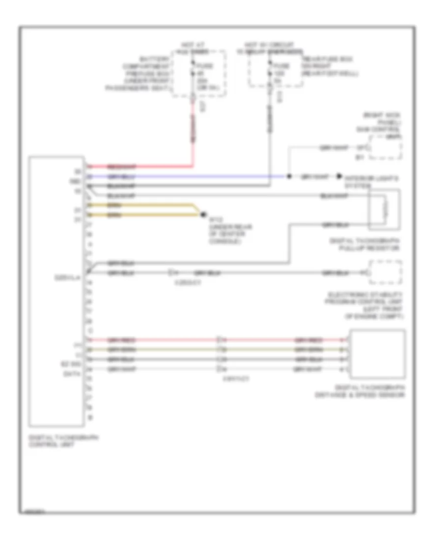
- Digital tachograph control unit (if equipped)
- Downhill speed regulation button
- Esp off button
- Esp warning lamp ind
- Esp/asr off warning lamp ind
- Fuse 5a
- Hot at all times
- Hot w/ circuit 30g relay energized
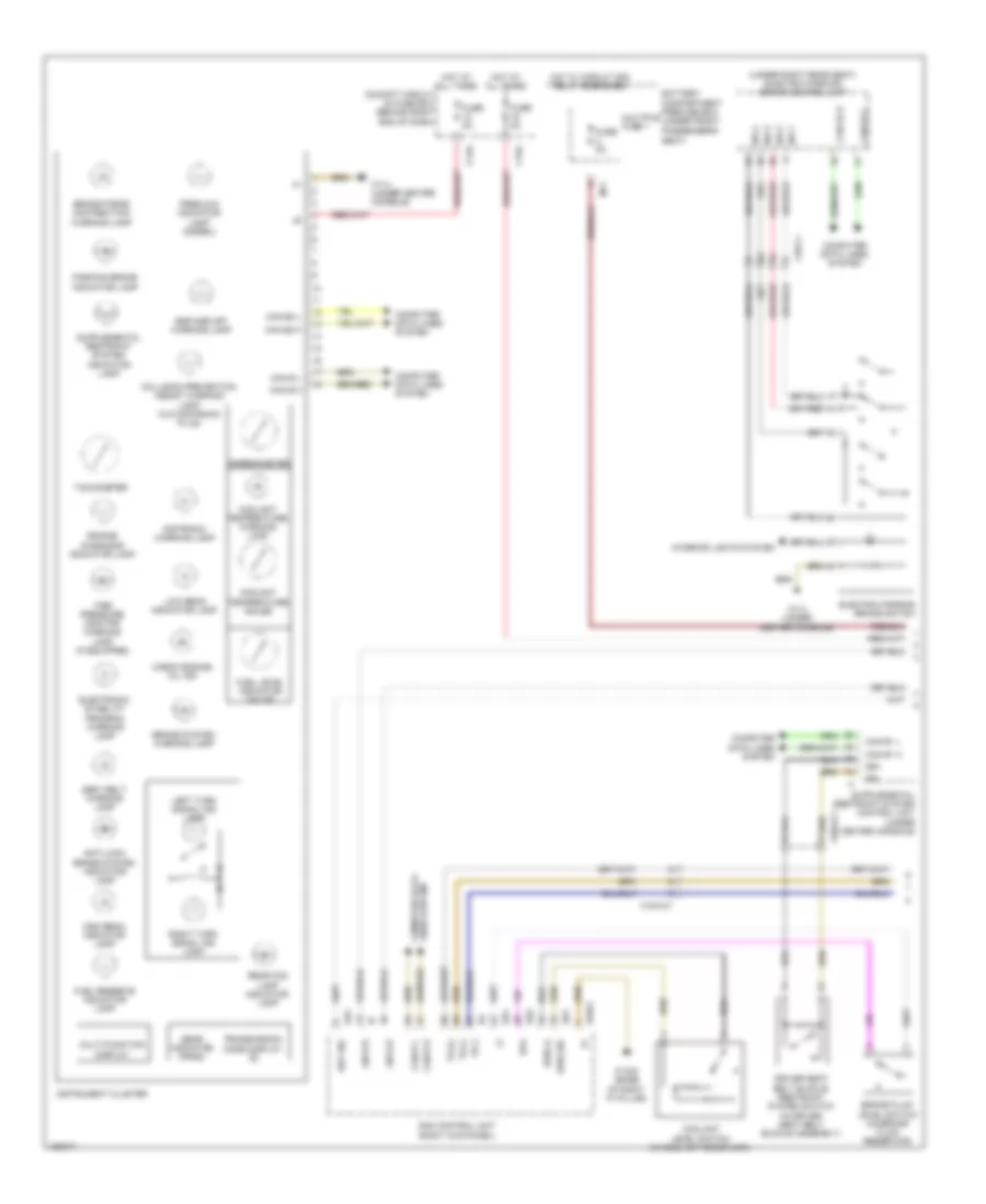
- Instrument cluster
- Left front axle rpm sensor (on left front wheel hub assemblies)
- Left rear axle rpm sensor (on left rear wheel hub assemblies)
- Lin
- Lin b15
- Low range button
- Lower control panel control unit
- Nca
- Off road program button
- Off-road operating panel control unit (if equipped)
- On-road/ off road menu button
- Parking brake ind
- Right front axle rpm sensor (on right front wheel hub assemblies)
- Right rear axle rpm sensor (on right rear wheel hub assemblies)
- Steering column module control unit (behind steering wheel)
- Steering wheel angle sensor (top of steering column)
- Uh1
- Uh2
- Upper control panel control unit
- W1/4 (under center console)
- W12 (under rear of center console)
- X25/2-c1
- X29/6-c1
ANTI-THEFT
Anti-theft Alarm Wiring Diagram (1 of 3) for Mercedes-Benz ML350 2014
List of elements for Anti-theft Alarm Wiring Diagram (1 of 3) for Mercedes-Benz ML350 2014:
- (integral to driver's outside door handle) driver door infrared remote control receiver
- (right front footwell) w15/1
- +5v
- 58d
- Battery compartment prefuse box (under front passenger's seat)
- Can b h
- Can b l
- Central locking motor
- Computer data lines system
- Data
- Driver side power window & outside mirror adjustment switch group
- Fuse 30a
- Fuse 40a
- Hot at all times
- Interior prefuse box (right front upper footwell)
- Left front door control module (in left front door)
- Left front door lock
- Left front door power closing actuator motor (w/ power closing for doors and trunk lid)
- Lin b5
- Mks art sig
- Mks-abh
- Mks-atr-sig
- Mks-ibh
- Mks-jbh
- Mks-vr-sig
- Pre-locking position micro switch
- Rear side window child safety lock switch
- Right front door central locking interior switch
- Right front door control module (in right front door)
- Right front door lock
- Right front door power closing actuator motor (w/ power closing for doors & trunk lid)
- Sec mot c
- Sec mot rs
- Ses mot c
- Ses mot rs
- Sig
- Sig-df
- W/ power closing for doors & trunk lid
- W/o power closing for doors & trunk lid
- W15/2 (left front footwell)
- X35/1-c1
- X35/2-c1
- Zv-c
- Zv-o
Anti-theft Alarm Wiring Diagram (2 of 3) for Mercedes-Benz ML350 2014
List of elements for Anti-theft Alarm Wiring Diagram (2 of 3) for Mercedes-Benz ML350 2014:
- (+)
- (base of right "a" pillar) w18/5
- (under right seat of 2nd row) w17
- 58d
- Can b h
- Can b l
- Can e2 h
- Can e2 l
- Can-b h
- Can-b l
- Central motor locking
- Computer data lines system
- Doors & trunk lid
- Instrument cluster
- Left front door central locking interior switch
- Left rear door control module (in left rear door)
- Left rear door lock
- Left rear door power closing actuator motor (w/ power closing for doors & trunk lid)
- Liftgate locking pawl switch
- Mks abh
- Mks atr sig
- Mks ibh
- Mks vr sig
- Multi-function display
- Pre-locking position micro switch
- Pwr1
- Rear control unit (under center of rear seats)
- Rotary tumbler switch
- Sam control unit (right kick panel)
- Ses mot c
- Ses mot rs
- Sig
- Sig df
- Tailgate central locking motor
- Tailgate control button
- Tank cap central locking actuator
- W/ power closing for
- W/o power closing for
- W17/1 (under left seat of 2nd row)
- W7 (base of right "d" pillar)
- W8 (right side of tailgate)
- X35/3-c1
- Zv-c
- Zv-o
Anti-theft Alarm Wiring Diagram (3 of 3) for Mercedes-Benz ML350 2014
List of elements for Anti-theft Alarm Wiring Diagram (3 of 3) for Mercedes-Benz ML350 2014:
- (base of right "a" pillar) w18/5
- 58d
- Anti-theft alarm system/emergency call system button group (if equipped)
- Ata (edw) function indicator
- Ata (edw)/towing sensor/interior motion sensor control unit (in roof console)
- Battery compartment prefuse box (under front passenger's seat)
- Bus
- Can b h
- Can b l
- Central locking motor
- Computer data lines system
- Doors & trunk lid
- Fuse 15a
- Fuse 30a
- Fuse 5a
- Hot at all times
- Led
- Lin
- Lin b 13
- Mks abh
- Mks ibh
- Mks vr sig
- Mks-atr-sig
- Overhead control panel control unit
- Pre-locking position position micro switch
- Rear fuse box (in right rear footwell)
- Red
- Right rear door control module (in right rear door)
- Right rear door lock
- Right rear door power closing actuator motor (w/ power closing for doors & trunk lid)
- Ses-mot-c
- Ses-mot-rs
- Sig
- Sig df
- Upper control panel control unit
- W/ power closing for
- W/o power closing for
- W17/6 (ml class) w17 (gl class) (under right seat of 2nd row)
- W18/5 (base of right "a" pillar)
- X35/4-c1
- Zv-c
- Zv-o
Panic Alarm Wiring Diagram for Mercedes-Benz ML350 2014
List of elements for Panic Alarm Wiring Diagram for Mercedes-Benz ML350 2014:
- Al e
- Al st
- Can b h
- Can b l
- Computer data lines system
- Fuse 10a
- Hot at all times
- Left footwell emergency alarm system button
- Left outside mirror pas (gas) microphone
- Ls a 1 (+)
- Ls a 1 (-)
- Mic gnd
- Mic ls (+)
- Mic ls (-)
- Mic nf (+)
- Mic vcc
- Microphone electrical connector
- Nca
- Outside pas (gas) speaker
- Pas (gas) control unit
- Ptt al a
- Rd m
- Rear air vent emergency alarm system button
- Rear fuse box (in right rear footwell)
- Red
- Right footwell emergency alarm system button
- Right outside mirror pas (gas) microphone
- Special vehicle multi-function control unit (svmcm (mss))
- Spmicro li (+)
- Spmicro li (-)
- Spmicro re (+)
- Spmicro re (-)
- T (-)
- W7/1
- Wsa
- X35/1-c1
- X35/2-c1
BODY CONTROL MODULES
Rear Control Unit Wiring Diagram for Mercedes-Benz ML350 2014
List of elements for Rear Control Unit Wiring Diagram for Mercedes-Benz ML350 2014:
- (+)
- 30g
- 58d
- Battery compartment prefuse box (under front passenger's seat)
- Can b h
- Can b l
- Computer data lines system interior lights system
- Door locks system
- Fuse 30a
- Hot at all times
- Interior lights system
- Ip-1
- Ip-2
- Nca
- Out
- Rear control unit (under center of rear seats)
- Rear fuse box (in right rear footwell)
- Right rear brake wear sensor (on right rear brake assembly)
- Seats system
- Sig
- Trunk, tailgate, fuel doors system
- W17 (under right seat of 2nd row)
- W17/6 (under right seat of 2nd row)
- X62/33-cb
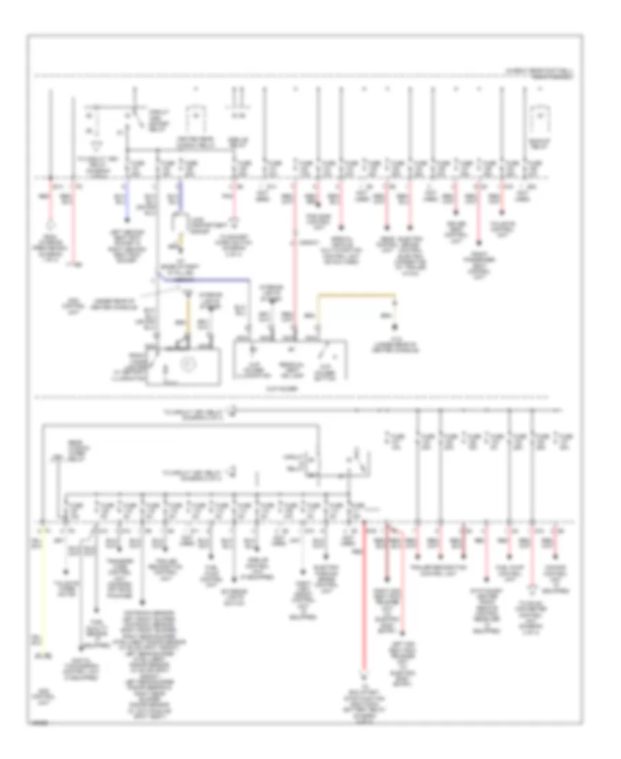
SAM Control Wiring Diagram (1 of 2) for Mercedes-Benz ML350 2014
List of elements for SAM Control Wiring Diagram (1 of 2) for Mercedes-Benz ML350 2014:
- 15 r
- 15 r1
- 15r2
- 30g
- 49 l
- Battery compartment prefuse box (under front passenger's seat)
- Bsl r
- Bub-l-el
- Bub-m
- Can b h
- Can b l
- Computer data lines system
- Door locks & anti-theft system
- Engine controls system
- Exterior lights system
- Fuse 40a
- Fuse 5a
- Hot at all times
- Hot w/ circuit 30g relay energized
- Instrument cluster system
- Interior prefuse box (right front upper footwell)
- Lin b12
- Lin b13
- Lin b15
- Mf1
- Multiple fuse 1
- Off high
- Off low
- On high
- On low
- Power distribution system
- Pwr1
- Pwr2
- Rel-bub
- Rel-ek
- Rel-hw
- Rfl r
- Sam control unit (right kick panel)
- Seats system
- Sig
- Sl l
- Starting/charging system
- Ts(+)
- Ts(-)
- Ts-2
- W18/5 (base of right "a" pillar)
- Wiper/washer system
SAM Control Wiring Diagram (2 of 2) for Mercedes-Benz ML350 2014
List of elements for SAM Control Wiring Diagram (2 of 2) for Mercedes-Benz ML350 2014:
- (-)
- (12 to 23 not used)
- 15-rmr
- 30 l
- 30l
- 31b
- 49 r
- 49a l
- 49a r
- 55 l
- 55r
- 56a l
- 56a r
- 56b l
- 56br
- 57 l
- 57 r
- 58 l
- 58 r
- 58-d
- Air conditioning & cooling fans systems
- Anti-lock brakes system
- Anti-theft system
- At(-)
- At-sig
- Bbv-sig
- Bfs
- Bsl l
- Can b h
- Can b l
- Computer data lines system
- Edw sig
- Engine controls system
- Exterior lights system
- Frl hl
- Frl hr
- Frl v
- Ft-r-e-a
- Ft-r-s-t
- Headlights system
- Horns system
- Hw crash
- Instrument cluster system
- Interior lights & exterior lights systems
- Interior lights system
- Interior lights systems
- Kfr bel
- Kws(-)
- Kws-sig
- Kzl l
- Kzl r
- Lds 1
- Lds 2
- Lds 3
- Lin b15
- Lwr
- Memory systems
- Mhs re
- Nca
- Nsi l
- Rel-ff
- Rfl l
- Right front brake wear sensor (on right front brake assembly)
- Sam control unit (right kick panel)
- Sl r
- Sra-p
- Tbbel-l
- Tbbel-r
- Tfl l
- Tfl r
- Uh1
- Uh2
- W2 (right side of engine compt)
- Wiper/washer system
- Wp h(+)
- Wp v(+)
- Wsa
- Wwhzg
- Wws(-)
- Wws-sig
- X62/36-c1
COMPUTER DATA LINES
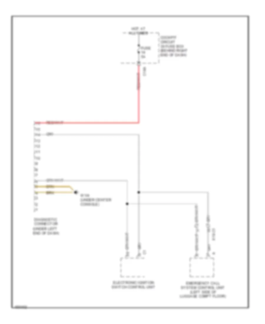
Data Link Connector Wiring Diagram for Mercedes-Benz ML350 2014
List of elements for Data Link Connector Wiring Diagram for Mercedes-Benz ML350 2014:
- (under left end of dash)
- C14a
- Cockpit circuit 30 fuse box (behind right end of dash)
- Diagnostic connector
- Electronic ignition switch control unit
- Emergency call system control unit (left side of luggage compt floor)
- Fuse 5a
- Hot at all times
- W1/4 (under center console)
- X18-c1
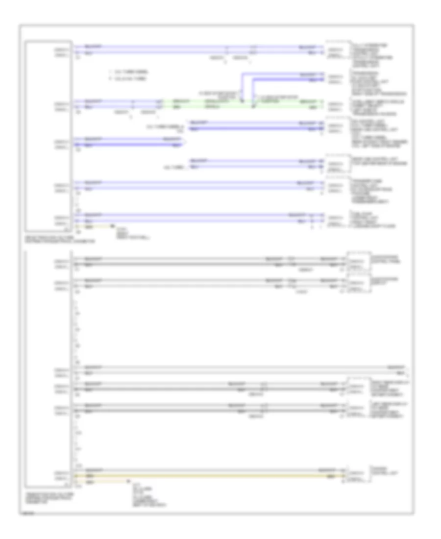
High/Low Bus Wiring Diagram (1 of 5) for Mercedes-Benz ML350 2014
List of elements for High/Low Bus Wiring Diagram (1 of 5) for Mercedes-Benz ML350 2014:
- 3.0l turbo diesel
- 3.0l turbo diesel & 3.5l
- 3.5l & 4.6l turbo
- 4.6l turbo
- Audio/comand control panel
- Audio/comand display
- C10
- C11
- C12
- C13
- Can-a h
- Can-a l
- Can-c h
- Can-c l
- Cdi control unit (3.0l turbo diesel) me-sfi (me) control unit (3.5l) (3.0l turbo diesel: rear of right front fender) (3.5l: left side of engine)
- Comand control unit
- Drive train can voltage distributor electrical connector
- Fuel pump control unit (right front luggage compt floor)
- Fully integrated transmission control unit (in fully integrated transmission control unit)
- Intelligent servo module (direct select) (left side of transmission housing)
- Left rear display (w/ rear compartment entertainment)
- Me-sfi (me) control unit (top center rear of engine)
- Right rear display (w/ rear compartment entertainment)
- Telematics can voltage distributor electrical connector
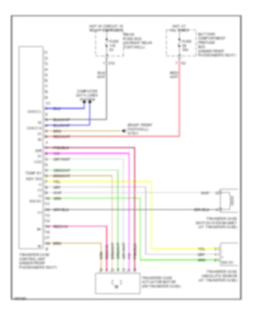
- Transfer case control unit (w/ on road/off road package) (under front passenger's seat)
- Transmission oil auxiliary pump control unit (w/ eco start/ stop function) (right side of transmission)
- W/ eco start/stop function
- W15/1 (right front footwell)
- W17 (gl class) w17/6 (ml class) (under right seat of 2nd row)
- X18-c1
- X22/2-c1
- X22/2-c2
- X29/6-c1
- X55/3-c3
- X55/4-c3
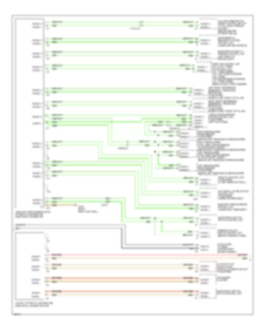
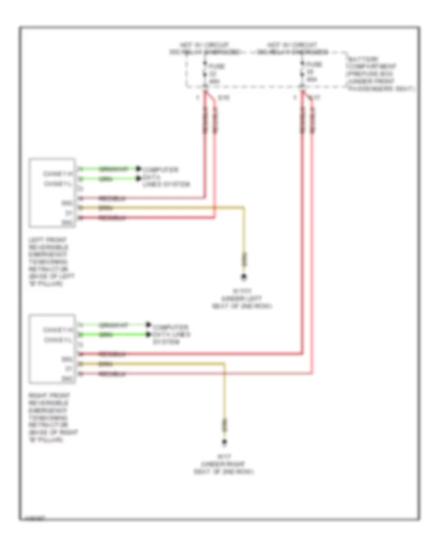
High/Low Bus Wiring Diagram (2 of 5) for Mercedes-Benz ML350 2014
List of elements for High/Low Bus Wiring Diagram (2 of 5) for Mercedes-Benz ML350 2014:
- Active roll stabilization control unit (if equipped) (under driver's seat)
- Airmatic control unit (if equipped) (in left rear footwell)
- Automatic air conditioning control & operating unit (if equipped)
- C10
- C11
- C12
- C13
- Can
- Can-a h
- Can-a l
- Can-b h
- Can-b l
- Can-e1 h
- Can-e1 l
- Can-s h
- Can-s l
- Cockpit potential distributor electrical connector (can)
- Collision prevention assist controller unit (w/ collision warning system) (behind center of front grille)
- Dvd player (w/ rear compartment entertainment)
- Electric parking brake control unit (under right rear seat)
- Electronic ignition switch control unit
- Electronic stability program control unit (left front of engine compt)
- Instrument cluster
- Left front reversible emergency tensioning retractor (if equipped) (base of left front "b" pillar)
- Left rear bumper radar sensor (if equipped) (behind left rear end of rear bumper)
- Me-sfi (me) control unit (3.5l & 4.6l turbo) cdi control unit (3.0l turbo diesel) (3.5l: left side of engine) (4.6l turbo: top center rear of engine) (3.0l turbo diesel: (rear of right front fender)
- Right front reversible emergency tensioning retractor (if equipped) (base of right front "b" pillar)
- Right rear bumper intelligent radar sensor (w/ blind sport assist) (behind right rear end of rear bumper) left rear bumper intelligent radar sensor (w/ blind sport assist) (behind left rear end of rear bumper)
- Right rear bumper radar sensor (if equipped) (behind right rear end of rear bumper)
- Steering column module control unit (behind steering wheel)
- Vehicle floor chassis can e1 potential distributor electrical connector
- Video & radar sensor system control unit (if equipped) (left kick panel)
- W15/1 (right front footwell)
- X174/1-c1
- X18-c1
- X35/29-c1
- X35/29-c4
High/Low Bus Wiring Diagram (3 of 5) for Mercedes-Benz ML350 2014
List of elements for High/Low Bus Wiring Diagram (3 of 5) for Mercedes-Benz ML350 2014:
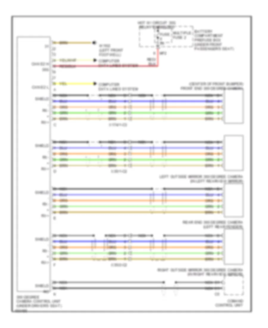
- 360 degree camera control unit (if equipped) (under driver's seat)
- Backup camera (center of tailgate)
- C10
- C11
- C12
- C13
- Can-b h
- Can-b l
- Can-e2 h
- Can-e2 l
- Electrical power steering control unit (on steering rack)
- Electronic ignition switch control unit
- Headlamp control unit (w/ xenon headlamps) (left rear of engine compt)
- Instrument cluster
- Multi-function camera (w/ speed limit assist & automatic lane detection) (center front of roof)
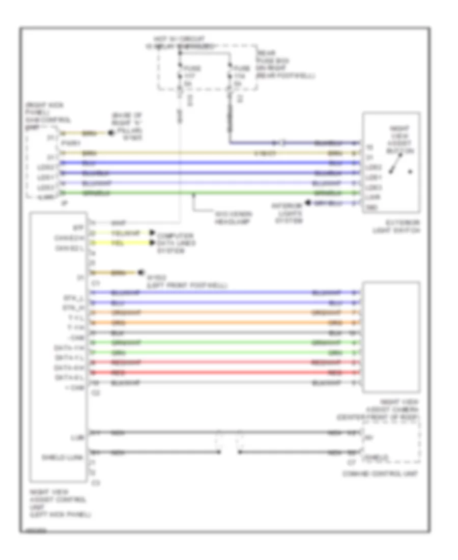
- Night view assist control unit (if equipped) (left kick panel)
- Parking system control unit (w/ parktronic) (under left rear seat)
- Right potential distributor electrical connector (can)
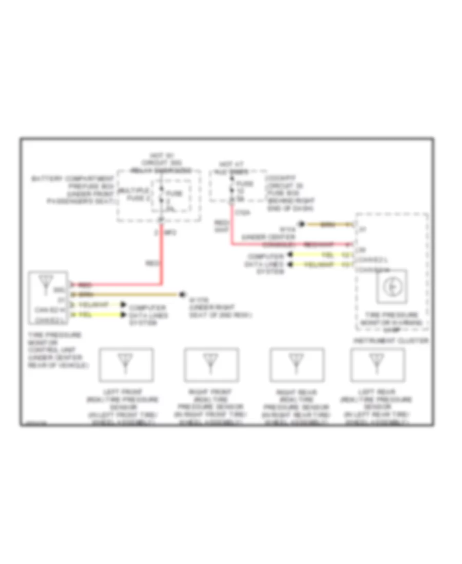
- Tire pressure monitor control unit (if equipped) (under center rear of vehicle)
- Trailer recognition control unit (w/ trailer hitch) (right side of luggage compt)
- Vehicle floor chassis can e2 potential distributor electrical connector
- W/ backup camera
- W/o backup camera
- W15/1 (right front footwell)
- X18-c1
- X26/13-c1
High/Low Bus Wiring Diagram (4 of 5) for Mercedes-Benz ML350 2014
List of elements for High/Low Bus Wiring Diagram (4 of 5) for Mercedes-Benz ML350 2014:
- Ata (edw)/towing sensor/ interior motion sensor control unit (if equipped) (in roof console)
- C10
- C11
- C12
- C13
- Can-b h
- Can-b l
- Comand control unit
- Driver seat control unit (under driver front seat)
- Front passenger seat control unit (under front passenger seat)
- Keyless-go control unit (if equipped) (under left rear seat)
- Left front door control unit (in left front door)
- Left potential distributor electrical connector (can)
- Left rear door control unit (in left rear door)
- Lin b12
- Lin b15
- Multicontour seat pneumatic pump (if equipped) (left side of luggage compt)
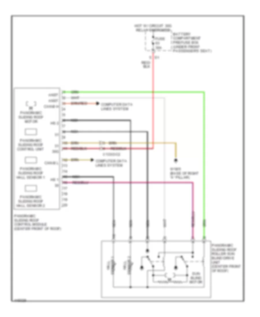
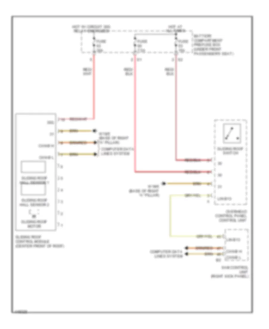
- Panoramic sliding roof control module (center front of roof)
- Rcp (hbf) control unit (w/ left & right rear seat heaters)
- Sliding roof control module (center front of roof)
- Tailgate control unit (if equipped) (right side of luggage compt)
- Upper control panel control unit
- W/ panoramic sliding sunroof
- X133/2-c2
- X29/6-c2
- X35/1-c1
- X35/3-c1
High/Low Bus Wiring Diagram (5 of 5) for Mercedes-Benz ML350 2014
List of elements for High/Low Bus Wiring Diagram (5 of 5) for Mercedes-Benz ML350 2014:
- (not used)
- (under vehicle, near left diesel particulate filter)
- 3.0l turbo diesel
- 3.5l
- Can-b h
- Can-b l
- Can-i h
- Can-i l
- Can-s h
- Can-s l
- Cdi control unit (rear of right front fender)
- Front passenger seat control unit (under passenger front seat)
- Left nox sensor control unit
- Lin 13
- Lin b12
- Lin b13
- Lin b15
- Lin-b12
- Lower control panel control unit (w/ on road/off road package & airmatic)
- Me-sfi (me) control unit (left side of engine)
- Nox sensor control unit downstream of diesel particulate filter
- Nox sensor control unit downstream of scr catalytic converter (3.0l turbo diesel)
- Off-road operating panel control unit (if equipped)
- Over head control panel control unit
- Pnk
- Potential distributor electrical connector (can i)
- Rear control unit (under center of rear seats)
- Right front door control unit (in right front door)
- Right nox sensor control unit (under vehicle, near right diesel particulate filter)
- Right rear door control unit (in right rear door)
- Sam control unit (right kick panel)
- Soot particulate sensor control unit (3.0l turbo diesel)
- Stationary heater unit (if equipped) (part of stationary heater unit)
- W15/1 (right front footwell)
- X25/2-c1
- X29/6-c1
- X35/2-c1
- X35/4-c1
COOLING FAN
Cooling Fan Wiring Diagram for Mercedes-Benz ML350 2014
List of elements for Cooling Fan Wiring Diagram for Mercedes-Benz ML350 2014:
- (-)
- (in right front wheelwell) w2/1
- (or tmot 1)
- 3.0l turbo diesel
- 3.5l
- 4.6l turbo
- 4.6l turbo & 3.5l
- Aav
- Activated charcoal filter shutoff valve (front of left front wheelwell)
- Automatic air conditioning control & operating unit
- Can-b h
- Can-b l
- Can-e1 h
- Can-e1 l
- Charge air cooler circulation pump (4.6l turbo) (lower right front of engine compt)
- Computer data lines system
- Coolant circulation pump (lower left front of engine compt)
- Coolant pump temperature sensor
- Engine compartment fuse & relay module (right side of engine compt)
- Engine compartment prefuse box (right rear of engine compt)
- Engine controls system
- Fan motor (behind radiator)
- Fuse 10a
- Fuse 125a
- Fuse 15a
- Gnd
- Hot at all times
- Hot w/ circuit 87m relay energized
- Hot w/ turbo charger relay energized
- Lues
- Me-sfi (me) control unit (4.6l turbo & 3.5l) cdi control unit (3.0l turbo diesel) (4.6l turbo: top center rear of engine) (3.5l: left side of engine) (3.0l turbo diesel: rear of right front fender)
- Pwm
- Red
- Refrigerant pressure sensor (left front of engine compt)
- Sig
- Tmot
- W52/11 (right rear of engine compt)
- W9 (left front of engine compt)
- X18-c1
- X25/2-c1
CRUISE CONTROL
Cruise Control Wiring Diagram (1 of 2) for Mercedes-Benz ML350 2014
List of elements for Cruise Control Wiring Diagram (1 of 2) for Mercedes-Benz ML350 2014:
- +5v
- 30g
- Accelerator pedal sensor (part of accelerator pedal assembly)
- Battery compartment prefuse box (under front passenger's seat)
- Can e1 h
- Can e1 l
- Can h h
- Can h l
- Can s h
- Can s l
- Can-e1 h
- Can-e1 l
- Computer data lines system
- Dcm
- Dcp
- Fuse 5a
- Hot at all times
- Hot in on or start
- Imp
- Ip1s
- Ip2s
- Left front bumper/ distronic sensor (dtr) (behind left side of front bumper)
- Left rear bumper radar sensor (behind left end of rear bumper)
- Lvds n
- Lvds p
- Me-sfi (me) control unit (3.5l & 4.6l turbo) (3.5l: left side of engine) (4.6l turbo: top center rear of engine)
- Mf3
- Multi-function camera (w/ active lane keeping assist) (center front of roof)
- Nca
- Rear fuse box (in right rear footwell)
- Right front bumper/ distronic sensor (dtr) (behind right side of front bumper)
- Right rear bumper radar sensor (behind right end of rear bumper)
- Shield
- Sp1s
- Sp2s
- Video & radar sensor system control unit (left kick panel)
- Video n
- Video p
- W15/1 (right front footwell)
- W15/2 (left front footwell)
- W2 (right side of engine compt)
- W6 (at left "d" pillar)
- X174/1-c1
- X25/2-c1
- X35/29-c1
Cruise Control Wiring Diagram (2 of 2) for Mercedes-Benz ML350 2014
List of elements for Cruise Control Wiring Diagram (2 of 2) for Mercedes-Benz ML350 2014:
- (+)
- 20a
- 3.5l
- 30g
- 4.6l turbo
- Accelerate/ set switch
- Accelerator pedal sensor (part of accelerator pedal assembly)
- Bls h
- Bls l
- Bls m
- Can b h
- Can b l
- Can c h
- Can c l
- Can e1 h
- Can e1 l
- Can h h
- Can h l
- Can-h h
- Can-h l
- Cdi control unit (3.0l turbo diesel) (rear of right front fender)
- Cockpit circuit 30g fuse box (behind right end of dash)
- Computer data lines system
- Cruise control lever
- Decelerate/ set switch
- Distronic control (if equipped)
- Distronic controller unit
- Distronic electronic controller
- Distronic radar sensor
- Dtr warning lamp ind
- Electronic stability program control unit (left front of engine compt)
- Engine compartment fuse & relay module (right side of engine compt)
- Fully integrated transmission control unit (in fully integrated transmission control control unit)
- Fuse 5a
- Fuse 7.5a
- Hot at all times
- Hot in on or start
- Ind switch
- Instrument cluster
- M (+)
- M (-)
- Off switch
- Output shaft rpm sensor
- Poti sig
- Power distribution system
- Resume from memory switch
- Sp1m
- Sp1s
- Sp2m
- Sp2s
- Steering column module control unit (behind steering wheel)
- Stop lamp switch (top of brake pedal assembly)
- Throttle valve actuator
- U pwg
- W1/4 (under center console)
- W2 (right side of engine compt)
- W52/11 (right rear of engine compt)
- X174/4-c1
- X25/2-c1
- X26-c3
- Yaw rate/lateral/ longitudinal acceleration sensor (under front passenger's seat)
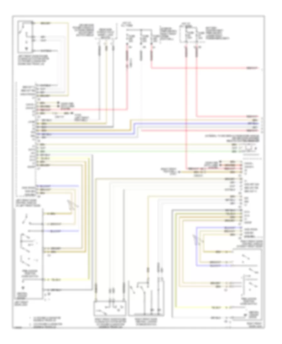
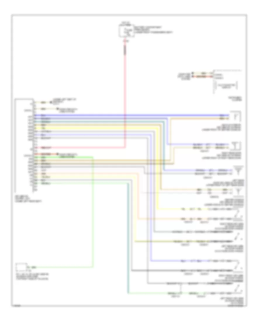
DEFOGGERS
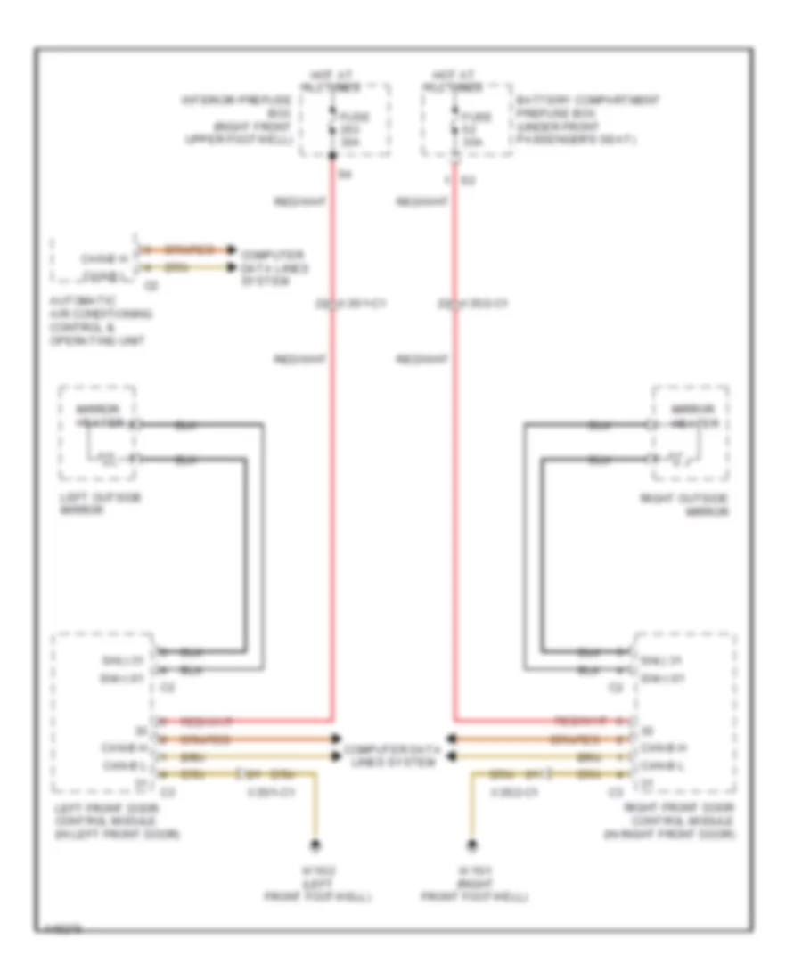
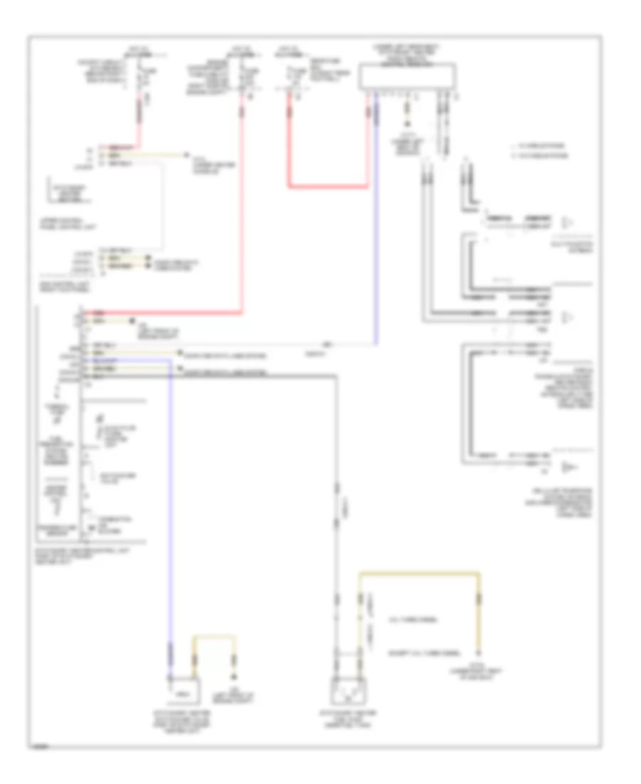
Heated Mirrors Wiring Diagram for Mercedes-Benz ML350 2014
List of elements for Heated Mirrors Wiring Diagram for Mercedes-Benz ML350 2014:
- Automatic air conditioning control & operating unit
- Battery compartment prefuse box (under front passenger's seat)
- Can-b h
- Can-b l
- Computer data lines system
- Fuse 30a
- Hot at all times
- Interior prefuse box (right front upper footwell)
- Left front door control module (in left front door)
- Left outside mirror
- Mirror heater
- Right front door control module (in right front door)
- Right outside mirror
- Sh(+) 61
- Sh(-) 31
- W15/1 (right front footwell)
- W15/2 (left front footwell)
- X35/1-c1
- X35/2-c1
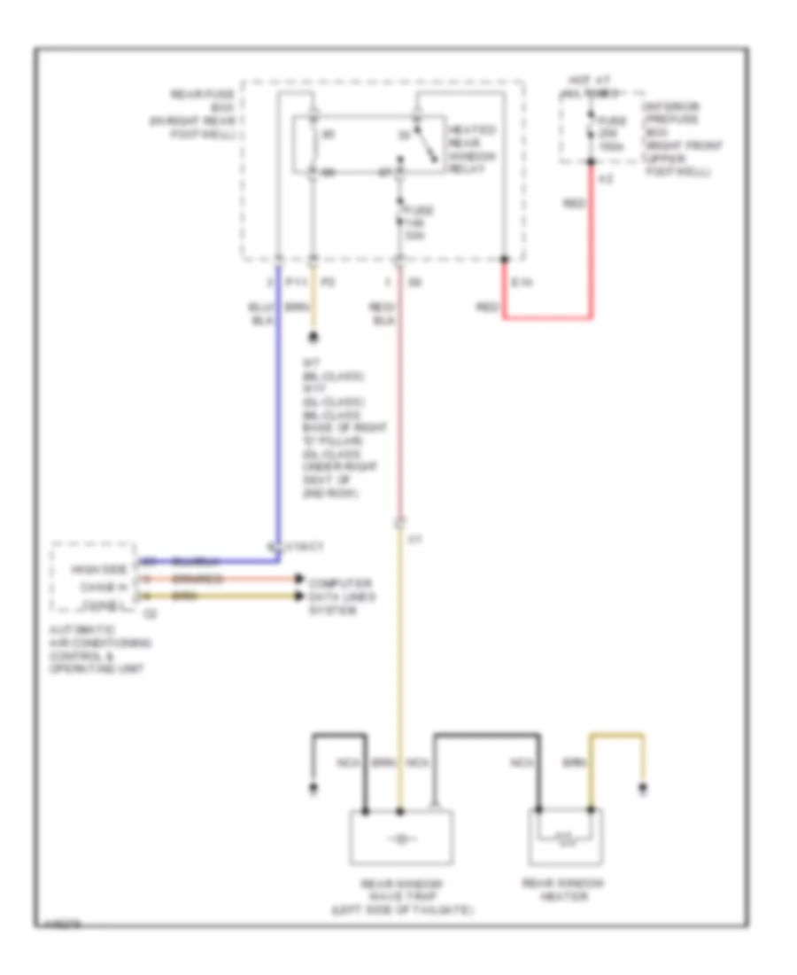
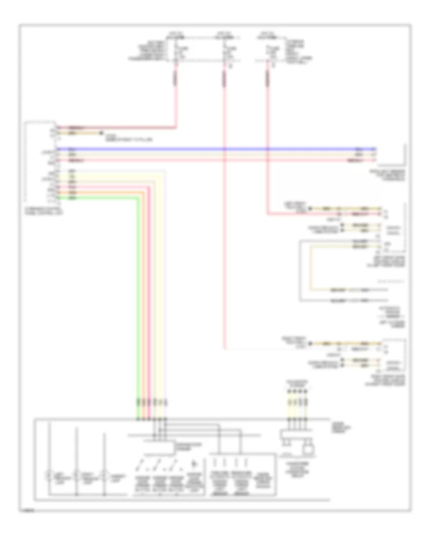
Rear Defogger Wiring Diagram for Mercedes-Benz ML350 2014
List of elements for Rear Defogger Wiring Diagram for Mercedes-Benz ML350 2014:
- Automatic air conditioning control & operating unit
- Can-b h
- Can-b l
- Computer data lines system
- E1a
- Fuse 150a
- Fuse 30a
- Heated rear window relay
- High side
- Hot at all times
- Interior prefuse box (right front upper footwell)
- Nca
- Rear fuse box (in right rear footwell)
- Rear window heater
- Rear window wave trap (left side of tailgate)
- Red
- W7 (ml-class) w17 (gl-class) (ml-class: base of right "d" pillar) (gl-class: under right seat of 2nd row)
- X18-c1
ELECTRONIC POWER STEERING
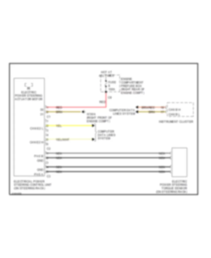
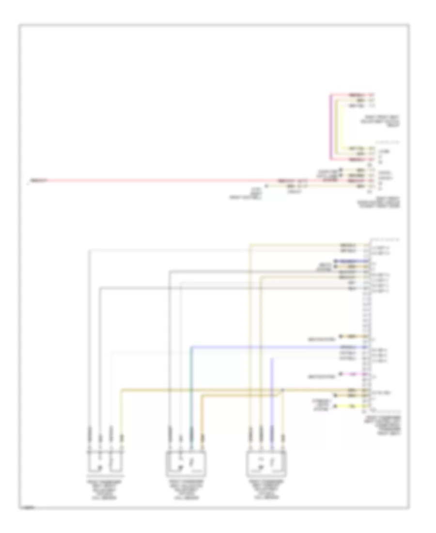
Electronic Power Steering Wiring Diagram for Mercedes-Benz ML350 2014
List of elements for Electronic Power Steering Wiring Diagram for Mercedes-Benz ML350 2014:
- Can b h
- Can b l
- Can e2 h
- Can e2 l
- Computer data lines system
- Electric power steering actuator motor
- Electric power steering torque sensor (on steering rack)
- Electrical power steering control unit (on steering rack)
- Engine compartment prefuse box (right rear of engine compt)
- Fuse 100a
- Gnd
- Hot at all times
- Instrument cluster
- Nca
- Pas a
- Pas b
- Red
- W30/4 (right front of engine compt)
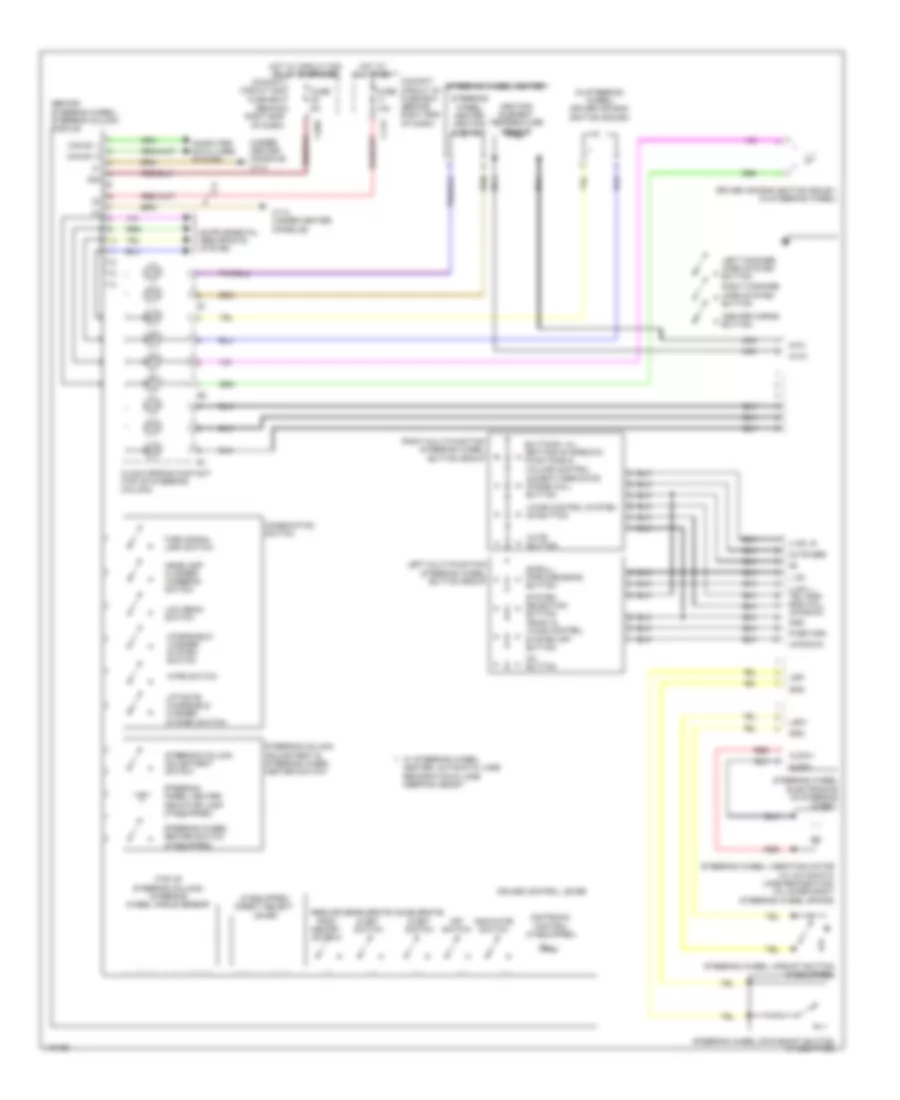
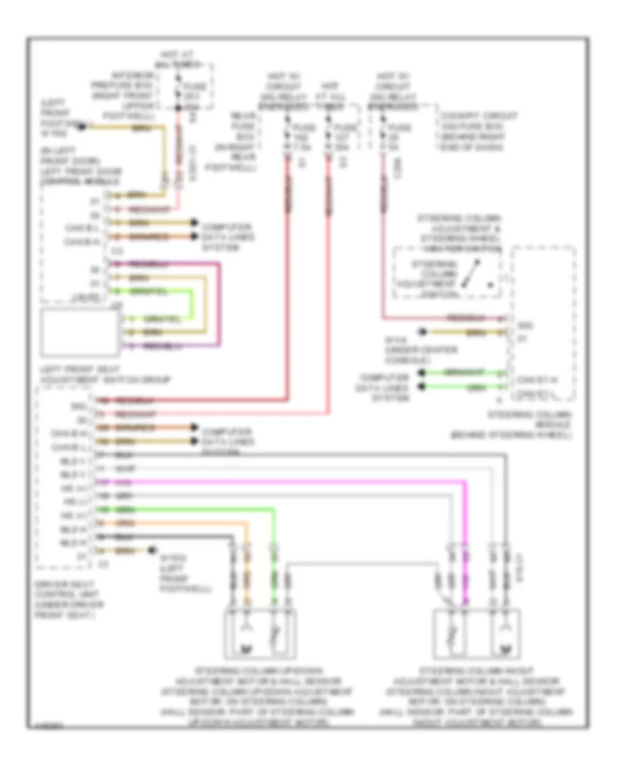
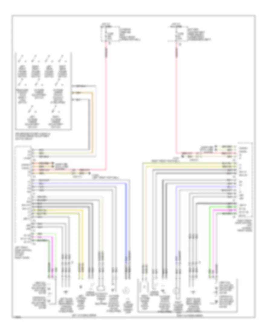
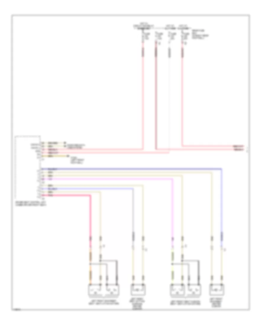
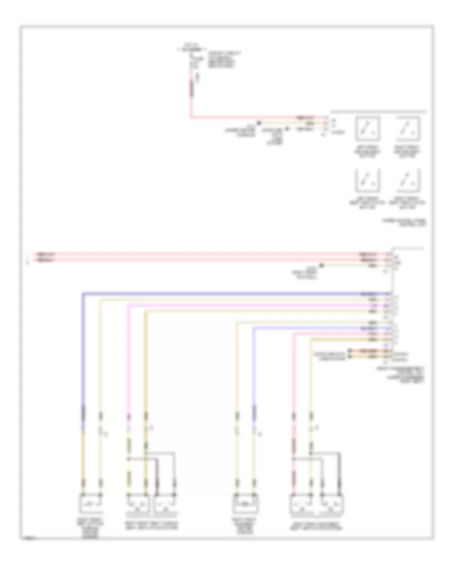
Power Steering Column Wiring Diagram for Mercedes-Benz ML350 2014
List of elements for Power Steering Column Wiring Diagram for Mercedes-Benz ML350 2014:
- "back" & voice control system off button
- (behind right end of dash)
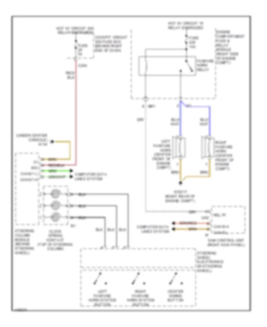
- (behind steering wheel) steering column module
- (if equipped) direct select lever
- (in steering wheel) driver air bag ignition squib 2
- (top of steering column) steering wheel angle sensor
- (under center console) w1/4
- 30g
- Accelerate & set switch
- Accept/terminate phone call button
- Aldw+
- Aldw-
- Buttons + & -, setting of specific functions & volume control
- C11a
- C20a
- Can e1 h
- Can e1 l
- Center horns button
- Clock spring contact (top of steering column)
- Cockpit circuit 30 fuse box (behind right end of dash)
- Cockpit circuit 30g fuse box
- Combination switch
- Computer data lines system
- Cruise control lever
- Decelerate & set switch
- Distronic control (if equipped)
- Driver air bag ignition squib 1 (in steering wheel)
- Fuse 10a
- Fuse 5a
- Gnd
- Headlamp flasher/ highbeam switch
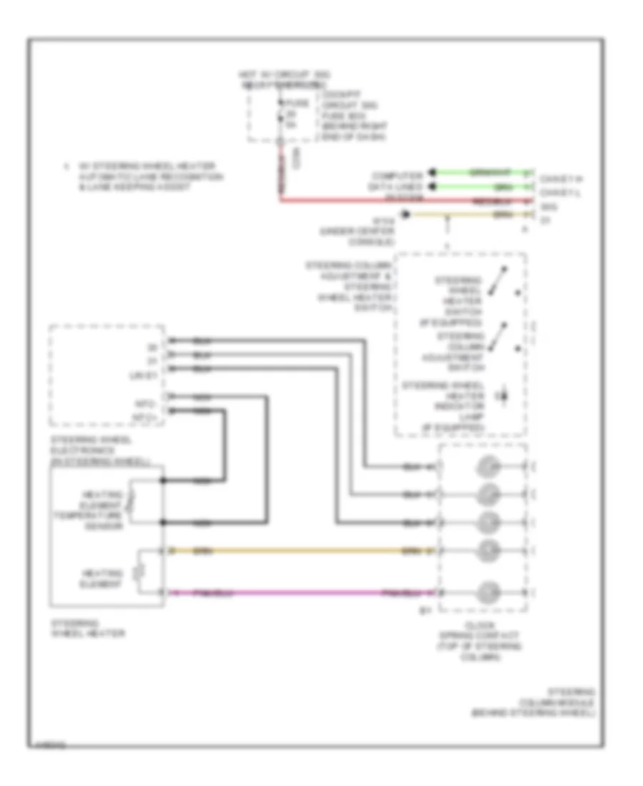
- Heating element temperature sensor
- Hot at all times
- Hot w/ circuit 30g relay energized
- Indicator switch
- L ok
- Left fanfare horn system button
- Left multi-function steering wheel button group
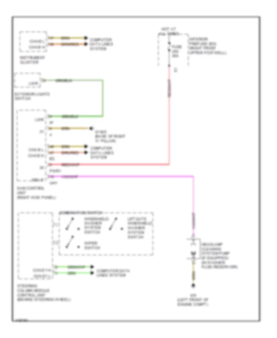
- Liftgate windshield washer system switch
- Low beam switch
- Lsp+
- Lsp-
- Mute button
- Mute sbs
- Nca
- Ntc+
- Ntc-
- Off switch
- Ok button
- R return
- Red
- Resume from memory switch
- Right fanfare horn system button
- Right multi-function steering wheel button group
- Scroll forward/back button
- Steering column adjustment & steering wheel heater switch
- Steering column adjustment switch
- Steering wheel downshift button (if equipped)
- Steering wheel electronics (in steering wheel)
- Steering wheel heater
- Steering wheel heater heating element
- Steering wheel heater indicator lamp (if equipped)
- Steering wheel heater switch (if equipped)
- Steering wheel upshift button (if equipped)
- Steering wheel vibration motor (w/ automatic lane recognition) (in lower right steering wheel spoke)
- System selection button
- Turn signal lamp switch
- U mfl l tel ans/ end call up/down
- U mfl r
- Up/down
- Voice control system on button
- W/ steering wheel heater, automatic lane recognition & lane keeping assist
- W1/4 (under center console)
- Windshield washer system switch
- Wipe switch
ELECTRONIC SUSPENSION
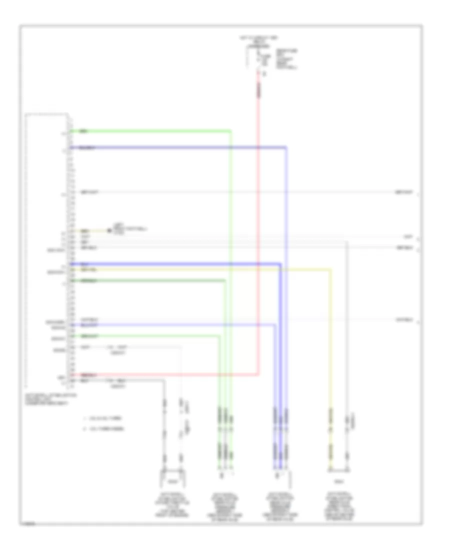
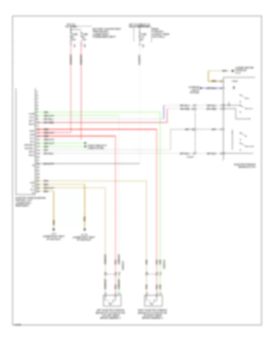
Active Body Control Wiring Diagram (1 of 2) for Mercedes-Benz ML350 2014
List of elements for Active Body Control Wiring Diagram (1 of 2) for Mercedes-Benz ML350 2014:
- (+)
- (-)
- (left front footwell) w15/2
- 15r1
- 3.0l turbo diesel
- 3.5l & 4.6l turbo
- Active roll stabilization control unit (under driver's seat)
- Active roll stabilization intake throttle valve (top center front of engine)
- Active roll stabilization rear axle directional control valve (above center of rear axle)
- Active roll stabilization rear axle pressure sensor 1 (above right side of rear axle)
- Active roll stabilization rear axle pressure sensor 2 (above right side of rear axle)
- Fuse 15a
- Hot w/ circuit 15r1 relay energized
- Rear fuse box (in right rear footwell)
- Sig
- Sig-ha1
- Sig-ha2
- Sig-hadrv
- Sig-hawv
- Sig-sd
- Sig-vawv
- X22/2-c2
- X25/2-c1
- X26-c1
- X62/39-c1
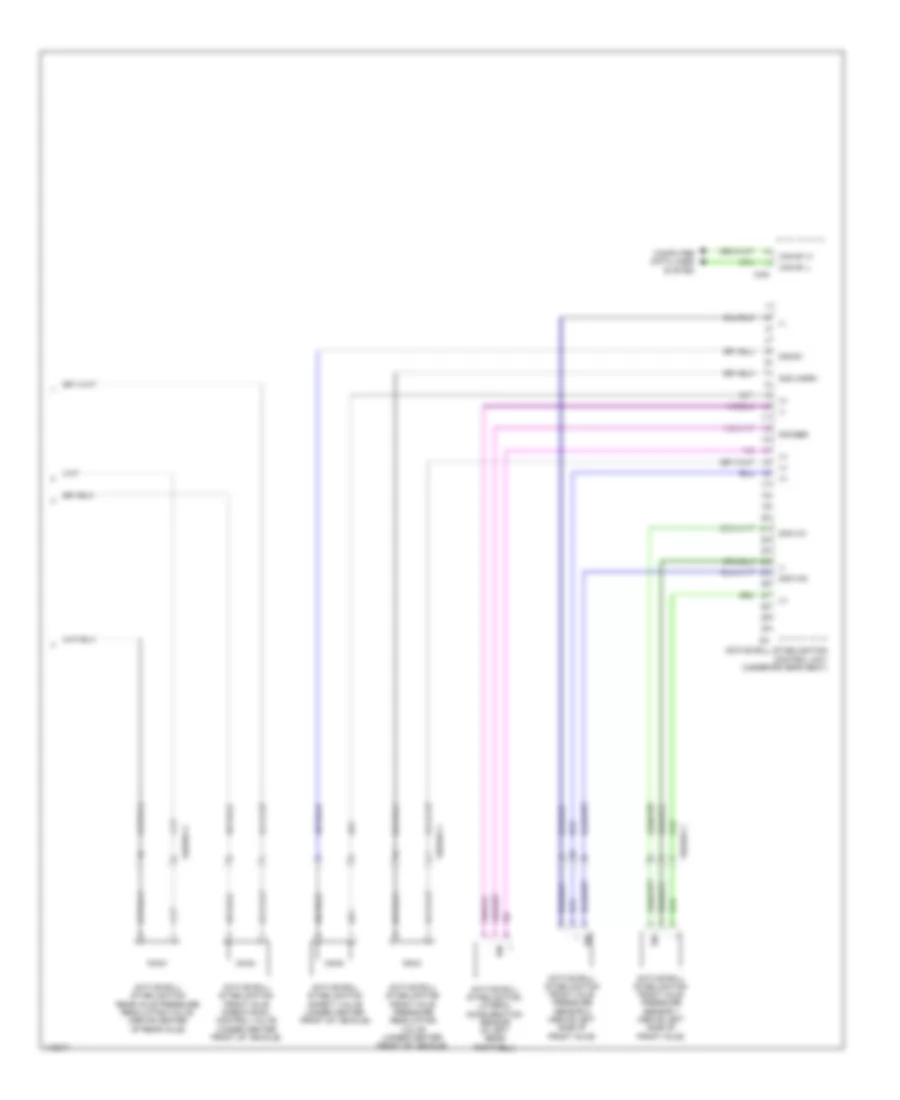
Active Body Control Wiring Diagram (2 of 2) for Mercedes-Benz ML350 2014
List of elements for Active Body Control Wiring Diagram (2 of 2) for Mercedes-Benz ML350 2014:
- (+)
- (-)
- Active roll stabilization control unit (under driver's seat)
- Active roll stabilization front axle directional control valve (under center front of vehicle)
- Active roll stabilization front axle pressure regulating valve (under center front of vehicle)
- Active roll stabilization front axle pressure sensor 1 (above left side of front axle)
- Active roll stabilization front axle pressure sensor 2 (above left side of front axle)
- Active roll stabilization lateral acceleration sensor (in left rear footwell)
- Active roll stabilization rear axle pressure regulating valve (above center of rear axle)
- Active roll stabilization safety valve (under center front of vehicle)
- Can
- Can e1 h
- Can e1 l
- Computer data lines system
- Sig
- Sig-qbs
- Sig-sv
- Sig-va1
- Sig-va2
- Sig-vadrv
- X62/39-c1
- X62/40-c1
Airmatic Control Wiring Diagram (1 of 2) for Mercedes-Benz ML350 2014
List of elements for Airmatic Control Wiring Diagram (1 of 2) for Mercedes-Benz ML350 2014:
- (-)
- 30g
- 87a
- 87b
- Ablv
- Airmatic compressor unit (behind right side of front bumper)
- Airmatic control unit (in left rear footwell)
- Airmatic pressure reduction valve
- Airmatic relay
- Battery compartment prefuse box (under front passenger's seat)
- Can e1 h
- Can e1 l
- Compressor motor
- Computer data lines system
- Dv1
- Dv2
- Dvv
- Engine compartment fuse & relay module (right side of engine compt)
- Engine compartment prefuse box (right rear of engine compt)
- Fuse 150a
- Fuse 15a
- Fuse 40a
- Fuse 5a
- Hot at all times
- Hot w/ circuit 30g relay energized
- Left front axle damping valve unit (w/ ads) (on left front axle shock absorber assembly)
- Left front level sensor (on left front axle suspension)
- Mf1
- Mr1
- Multi fuse
- Nca
- Nca valve 2 solenoid
- Pnk
- Red
- Rel sig
- Rel vers
- Right front axle damping valve unit (w/ ads) (on right front axle shock absorber assembly)
- Right front level sensor (on right front axle suspension)
- S11
- Sig
- Solenoid valve 1
- Solenoid valve 2
- Valve 1 solenoid
- W15/2 (left front footwell)
- W2 (right side of engine compt)
- W52/11 (right rear of engine compt)
- X25/2-c1
- Zlv
Airmatic Control Wiring Diagram (2 of 2) for Mercedes-Benz ML350 2014
List of elements for Airmatic Control Wiring Diagram (2 of 2) for Mercedes-Benz ML350 2014:
- (-)
- (not used)
- Airmatic central reservoir charge valve
- Airmatic valve unit (behind right end of front bumper)
- Computer data lines system
- Left front level control valve
- Left rear axle damping valve unit (w/ ads) (on left rear axle shock absorber assembly)
- Left rear level control valve
- Left rear level sensor (on left rear axle suspension)
- Low range button
- Lower control panel control unit
- Nca
- Pnk
- Pressure sensor
- Right front level control valve
- Right rear axle damping valve unit (w/ ads) (on right rear axle shock absorber assembly)
- Right rear level sensor (on right rear axle suspension)
- Right rear level valve
- Sig
- Solenoid valve 1
- Valve 1 solenoid
- Valve 2 solenoid
- Vehicle level button
- Vehicle level rotary switch
- W12 (under rear of center console)
- X29/6-c1
ENGINE ACCESSORIES
Stationary Heater Wiring Diagram for Mercedes-Benz ML350 2014
List of elements for Stationary Heater Wiring Diagram for Mercedes-Benz ML350 2014:
- (under left rear seat) stationary heater radio remote control receiver
- 3.0l turbo diesel
- Ant
- C15a
- Can b h
- Can b l
- Cellular telephone system antenna amplifier/compensator (left side of cargo area)
- Cockpit circuit 30 fuse box (behind right end of dash)
- Combustion air blower
- Computer data lines system
- Dopump
- Efb
- Engine compartment fuse & relay module (right side of engine compt)
- Except 3.0l turbo diesel
- Fuel preheating system heating element
- Fuse 20a
- Fuse 5a
- Glow plug/ flame monitor unit
- Heater control unit
- Hot at all times
- Lin b15
- Mobile phone & stationary heater radio remote control antenna splitter (left side of cargo area)
- Multi-function antenna
- Nca
- Rear fuse box (in right rear footwell)
- Red
- Sam control unit (right kick panel)
- Stationary heater button
- Stationary heater control unit (part of stationary heater unit)
- Stationary heater fuel pump (near fuel tank)
- Stationary heater switchover valve (part of stationary heater unit)
- Switchover valve
- Temperature sensor
- Tes
- Thermal fuse
- Uhi
- Upper control panel control unit
- Usv
- W/ mobile phone
- W/o mobile phone
- W1/4 (under center console)
- W17/1 (under left seat of) 2nd row)
- W17/6 (under right seat of 2nd row)
- W9 (left front of engine compt)
- X18/3-c1
- X18/3-c2
- X25/2-c1
ENGINE PERFORMANCE
3.0L TURBO DIESEL
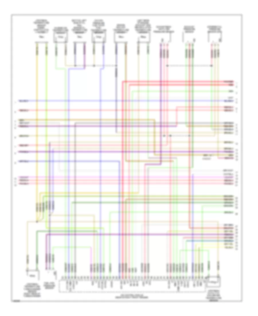
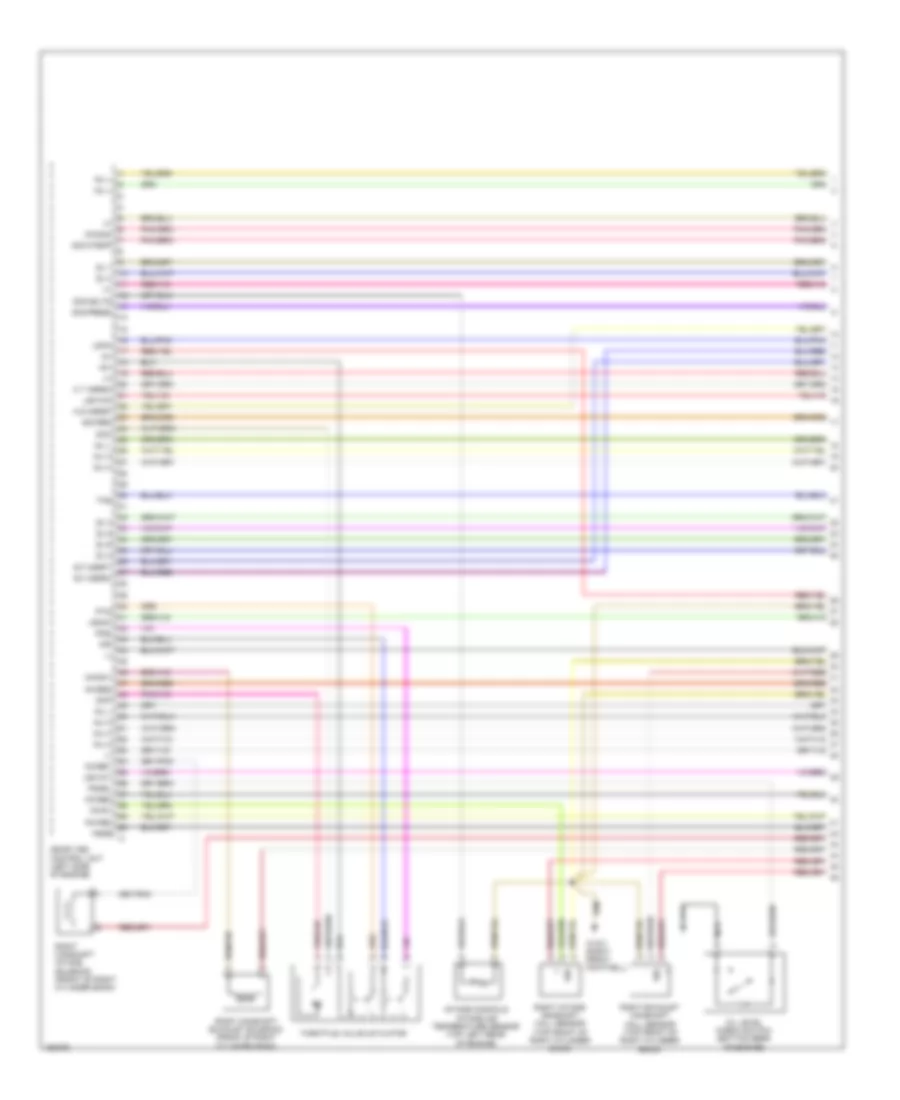
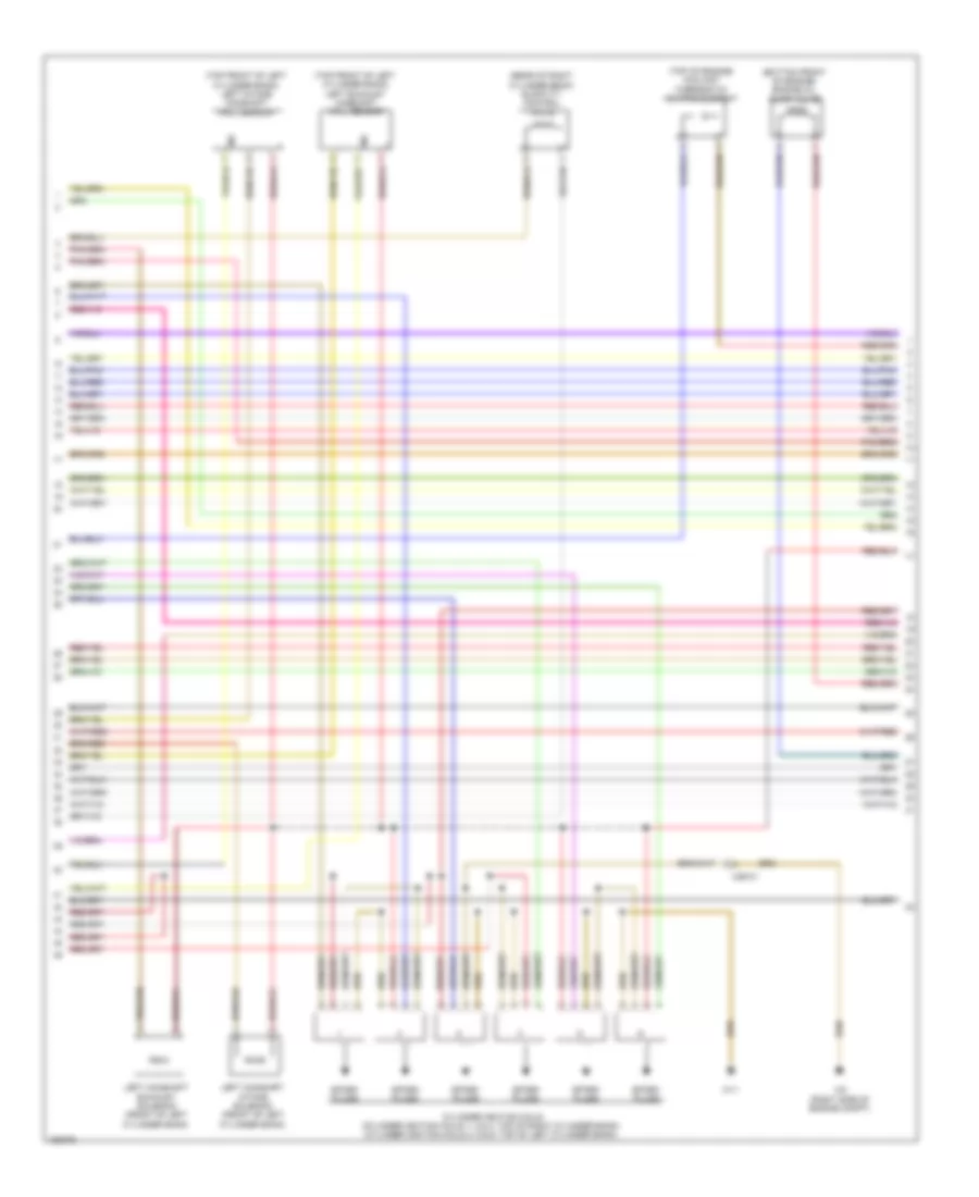
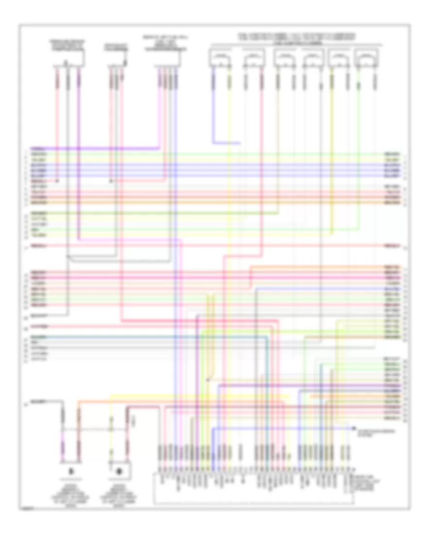
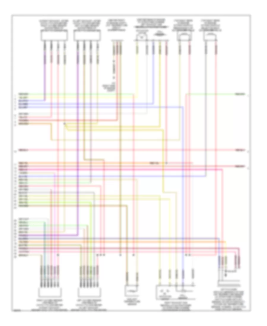
3.0L Turbo Diesel, Engine Performance Wiring Diagram (1 of 9) for Mercedes-Benz ML350 2014
List of elements for 3.0L Turbo Diesel, Engine Performance Wiring Diagram (1 of 9) for Mercedes-Benz ML350 2014:
- (+)
- (-)
- 87m1
- 87m2
- Accelerator pedal sensor (part of accelerator pedal assembly)
- Battery compartment prefuse box (under front passenger's seat)
- Can 1 l
- Can c h
- Can c l
- Can e h
- Can e l
- Can i h
- Cdi control unit (rear of right front fender)
- Circuit 87m relay
- Computer data lines system
- Cooling fans system
- Crash
- Differential pressure sensor/ diesel particulate filter for onboard diagnostics (obd) sensor
- Efp
- Engine compartment fuse & relay module (right side of engine compt)
- Exts3
- Exts4
- Fuse 15a
- Fuse 20a
- Fuse 40a
- Fuse 7.5a
- Hot at all times
- Kja
- Lues
- Mr2
- Mrly
- Pnk
- Radiator shutters actuator (if equipped) (upper right rear of radiator)
- S13
- Sam control unit (right kick panel)
- Sig
- Sp1m
- Sp1s
- Sp2s
- Starting/charging system
- Uh2
- Upstream temperature scr catalytic converter (w/ exhaust treatment)
- Upwg
- Vssam
- W/ eco start/stop function
- W2 (right side of engine compt)
- X25/2-c1
- X25/2-c2
- X26/31-c1
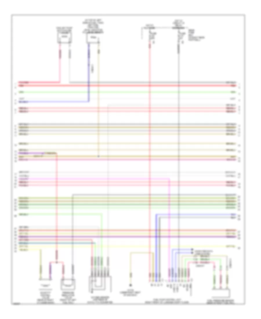
3.0L Turbo Diesel, Engine Performance Wiring Diagram (2 of 9) for Mercedes-Benz ML350 2014
List of elements for 3.0L Turbo Diesel, Engine Performance Wiring Diagram (2 of 9) for Mercedes-Benz ML350 2014:
- (+)
- Can i h
- Can i l
- Computer data lines system
- Dvhs (+)
- Dvhs (-)
- Gnd
- Hemt dl
- O s mrly
- O t raht1
- O t ramcp
- O t rapp
- O v ramcp
- O v rapp
- Pnk
- Sig
- W7 (base of right "d" pillar)
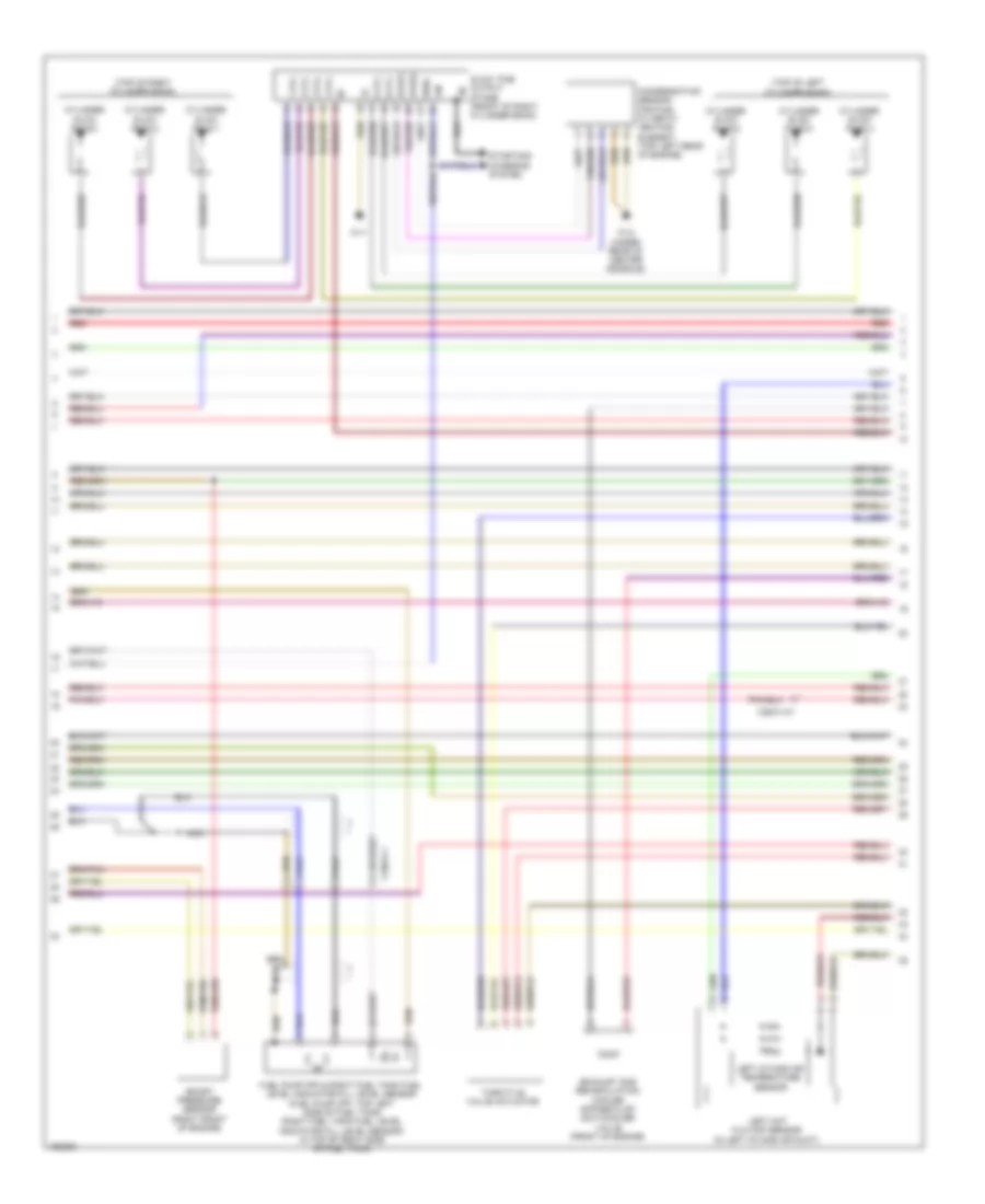
3.0L Turbo Diesel, Engine Performance Wiring Diagram (3 of 9) for Mercedes-Benz ML350 2014
List of elements for 3.0L Turbo Diesel, Engine Performance Wiring Diagram (3 of 9) for Mercedes-Benz ML350 2014:
- (-)
- (left bottom rear side of engine compt) left switchable engine mount
- (right bottom rear side of engine compt) right switchable engine mount
- Can i h
- Can i l
- E1a
- Early production
- Fuse 150a
- Fuse 15a 20a
- Fuse 20a 25a
- Fuse 5a
- Fuse 7.5a 15a
- Gr pras
- Hot at all times
- Hot w/ circuit 15 relay energized
- Ia pras
- Ia trats
- Interior prefuse box (right front upper footwell)
- Late production
- Lines system computer data
- Os rarv
- Ot rapmp
- Ov rh1
- Pnk
- Ramvh1
- Ramvl1
- Rear fuse box (in right rear footwell)
- Red
- Scrm1
- W7 (base of right "d" pillar)
3.0L Turbo Diesel, Engine Performance Wiring Diagram (4 of 9) for Mercedes-Benz ML350 2014
List of elements for 3.0L Turbo Diesel, Engine Performance Wiring Diagram (4 of 9) for Mercedes-Benz ML350 2014:
- (-)
- 15a
- Bf rals1
- Bf rals2
- Bf rals3
- Empty
- Fill level sensor
- Full
- Os raht1
- Os raht2
- Os raht3
- Pressure line heating element
- Red
- Reserve
- Scrm3
- Sp2m
- Tank heating element & temperature sensor
- Vv 5vpras
- W7 (base of right "d" pillar)
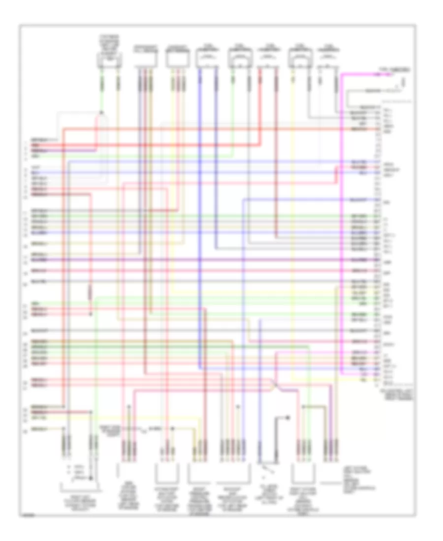
3.0L Turbo Diesel, Engine Performance Wiring Diagram (5 of 9) for Mercedes-Benz ML350 2014
List of elements for 3.0L Turbo Diesel, Engine Performance Wiring Diagram (5 of 9) for Mercedes-Benz ML350 2014:
- Can b h
- Can b l
- Computer data lines system
- Coolant temperature warning lamp indicator
- Delivery pump
- Engine compartment fuse & relay module (right side of engine compt)
- Engine diagnosis indicator lamp
- Fuel level indicator lamp
- Fuel reserve indicator lamp
- Fuse 15a
- Heating element
- Hot w/ circuit 87m relay energized
- Instrument cluster
- Nox sensor control unit downstream of diesel particulate filter
- Nox sensor control unit downstream of scr catalytic converter
- Nox sensor downstream of diesel particulate filter
- Nox sensor downstream of scr catalytic converter
- Pnk
- Preglow indicator lamp
- Pressure sensor
- Red
- Soot particulate sensor
- Soot particulate sensor control unit
- Switchover valve
- W15/1 (right front footwell)
- W7 (base of right "d" pillar)
- X25/2-c1
3.0L Turbo Diesel, Engine Performance Wiring Diagram (6 of 9) for Mercedes-Benz ML350 2014
List of elements for 3.0L Turbo Diesel, Engine Performance Wiring Diagram (6 of 9) for Mercedes-Benz ML350 2014:
- (+)
- (-)
- (bottom left side of oil pan) engine oil temperature sensor
- (left rear of engine) exhaust gas recirculation temperature sensor
- (on high pressure fuel pump) fuel temperature sensor
- +5v
- A-eka-r
- Aldr
- Cdi control module (rear of right front fender)
- Charge air temperature sensor
- Differential pressure sensor (dpf)
- Downstream air filter pressure sensor
- Dpf sig
- Ea lds
- Engine coolant temperature sensor
- Ep3
- Exhaust pressure sensor
- Exts1
- Exts2
- Fuel high pressure sensor
- Inj h
- Kts sig
- Lin c1
- Lltf sig
- Lscp1
- Lsh1
- Lsvg1
- Lsvn1
- Oel temp
- Pnk/red
- Rds
- Red
- Sig
- T sig
- Temp agr
- Tmot
- Upstream catalytic converter temperature sensor
- Upstream temperature sensor diesel particulate filter
- Upstream temperature turbocharger sensor (right rear of turbocharger)
- X18/3-c1
- Zme+
3.0L Turbo Diesel, Engine Performance Wiring Diagram (7 of 9) for Mercedes-Benz ML350 2014
List of elements for 3.0L Turbo Diesel, Engine Performance Wiring Diagram (7 of 9) for Mercedes-Benz ML350 2014:
- (+)
- (-)
- (in top of left side of fuel tank) left fuel tank fuel level indicator fill level sensor
- Can c h
- Can c l
- Computer data lines system
- Coolant pump switchover valve
- Ds sig
- Ds+
- Ds-
- Ekp
- Fuel pressure sensor (rear of right fuel rail)
- Fuel pump control unit (right front of luggage compt floor)
- Fuse 25a
- Fuse 5a
- Hot at all times
- Hot w/ circuit 15 relay energized
- Nca
- Oxygen sensor upstream of catalytic converter
- Pnk/red
- Pressure regulator valve (front of left fuel rail)
- Quantity control valve (rear of right cylinder bank)
- Rear fuse box (in right rear footwell)
- Red
- W17/6 (under right seat of 2nd row)
- X18/3-c1
- X25/2-c1
- X26/31-c1
3.0L Turbo Diesel, Engine Performance Wiring Diagram (8 of 9) for Mercedes-Benz ML350 2014
List of elements for 3.0L Turbo Diesel, Engine Performance Wiring Diagram (8 of 9) for Mercedes-Benz ML350 2014:
- (top of left cylinder bank)
- (top of right cylinder bank)
- 1 zyl
- 2 zyl
- 3 zyl
- 4 zyl
- 5 zyl
- 6 zyl
- Boost pressure sensor (right front of engine)
- Condensation sensor for fuel filter w/ heating element (top left rear of engine)
- Cylinder glow plug 1
- Cylinder glow plug 2
- Cylinder glow plug 3
- Cylinder glow plug 4
- Cylinder glow plug 5
- Cylinder glow plug 6
- Exhaust gas recirculation cooler bypass flap switchover valve (front of engine)
- Fuel pump (fp) & right fuel tank fuel level indicator fill level sensor (fuel pump (fp): top left side of fuel tank) (right fuel tank fuel level indicator fill level sensor: in top of right side of fuel tank)
- Glow time output stage (front of right cylinder bank)
- Kfhz2
- Kfzh1
- Left hot film maf sensor (in left intake air duct)
- Left intake air temperature sensor
- Lin
- Nca
- Red
- Starting/ charging system
- Throttle valve actuator
- W11
- W12 (under rear of center console)
- Wss
- X18/3-c1
- X26/31-c1
3.0L Turbo Diesel, Engine Performance Wiring Diagram (9 of 9) for Mercedes-Benz ML350 2014
List of elements for 3.0L Turbo Diesel, Engine Performance Wiring Diagram (9 of 9) for Mercedes-Benz ML350 2014:
- (+)
- (-)
- (right side of engine compt)
- (top rear of engine) vent line heater element
- Aeka
- Agr
- Arg bvp
- Boost pressure control pressure transducer (top center of engine)
- Camshaft hall sensor
- Cdi control unit (rear of right front fender)
- Crankshaft hall sensor
- Dpf
- Drv
- Egr cooler bypass flap hall sensor (left rear of engine)
- Eti 1
- Eti 2
- Exhaust gas recirculation actuator (top left rear of engine)
- Fuel injector 1
- Fuel injector 2
- Fuel injector 3
- Fuel injector 4
- Fuel injector 5
- Fuel injector 6
- Gnd
- Hfm-1
- Hfm-2
- Inj h
- Inj l
- Intake port shutoff actuator motor (top center of engine)
- Kwg
- Left intake port shutoff hall sensor (on left intake manifold port)
- Mot (+)
- Mot (-)
- Nca
- Ods
- Oil level check switch (left front of oil pan)
- Pnk/red
- Red
- Right hot film maf sensor (in right intake air duct)
- Right intake port shutoff hall sensor (on right intake manifold port)
- S-chv
- Sig
3.5L
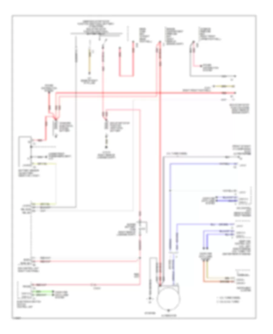
3.5L, Engine Performance Wiring Diagram (1 of 6) for Mercedes-Benz ML350 2014
List of elements for 3.5L, Engine Performance Wiring Diagram (1 of 6) for Mercedes-Benz ML350 2014:
- (+)
- (-)
- +5v
- A s agr2p
- A t agr2m
- Dcm
- Dcp
- E f agrp1
- E f agrp2
- Fsoel
- Imp
- Inj h
- Inj l
- Intake manifold intake air temperature sensor (top left rear of engine)
- Ip1s
- Ip2s
- Ks2b
- Ls2hk
- Lsh1hk
- Lshk
- Lshvk1
- Me-sfi (me) control unit (left side of engine)
- Nca
- Nwae2
- Nwg1
- Nwge2
- Nwsa1
- Nwsa2
- Nwse1
- Nwse2
- Oil level check switch (bottom rear of engine)
- Right camshaft exhaust solenoid (front of right cylinder bank)
- Right camshaft intake solenoid (front of right cylinder bank)
- Right exhaust camshaft hall sensor (top front of right cylinder bank)
- Right intake camshaft hall sensor (top front of right cylinder bank)
- Sig
- Sig ntemp
- Sig res
- Sig-aslts
- Sig-press
- Throttle valve actuator
- Ths
- W15/1 (right front footwell)
- Zu 1
- Zu 2
- Zu 3
- Zu 4
- Zu 5
- Zu 6
3.5L, Engine Performance Wiring Diagram (2 of 6) for Mercedes-Benz ML350 2014
List of elements for 3.5L, Engine Performance Wiring Diagram (2 of 6) for Mercedes-Benz ML350 2014:
- (bottom front of engine) engine oil pump valve
- (rear of right cylinder bank) quantity control valve
- (top front of left cylinder bank) left exhaust camshaft hall sensor
- (top front of left cylinder bank) left intake camshaft hall sensor
- (top of engine) coolant thermostat heating element
- Cylinder ignition coils (cylinder ignition coils 1, 2 & 3: top of right cylinder bank) (cylinder ignition coils 4, 5 & 6: top of left cylinder bank)
- Left camshaft exhaust solenoid (front of left cylinder bank)
- Left camshaft intake solenoid (front of left cylinder bank)
- Sig
- Spark plugs
- W11
- W2 (right side of engine compt)
- X26-c1
3.5L, Engine Performance Wiring Diagram (3 of 6) for Mercedes-Benz ML350 2014
List of elements for 3.5L, Engine Performance Wiring Diagram (3 of 6) for Mercedes-Benz ML350 2014:
- (+)
- (-)
- (fuel injector cylinders 1, 2 & 3: top of right cylinder bank) (fuel injector cylinders 4, 5 & 6: top of left cylinder bank) fuel injector cylinders
- (rear of left fuel rail) fuel tank pressure & temperature sensor
- + -
- A t agr1m
- A t agr1p
- Crankshaft hall sensor
- Ef hfm1
- Inj h
- Inj l
- Knock sensor 1 (under intake manifold, on front of left cylinder bank)
- Knock sensor 2 (under intake manifold, on middle of left cylinder bank)
- Ks1a
- Ks1b
- Ks2a
- Kwga
- Lin c1
- Lsh2hk
- Lshvk2
- Lsu1a
- Lsu1p
- Lsu1un
- Lsu1vm
- Lsu2ia
- Lsu2ip
- Lsu2un
- Lsu2vm
- Me-sfi (me) control unit (left side of engine)
- Nwga1
- Pnk
- Pressure sensor downstream of throttle valve
- Ref1
- Sig
- Sig pmot
- Sig sw
- Sig-temp
- Starting/charging system
- Tmot1
- X26-c4
3.5L, Engine Performance Wiring Diagram (4 of 6) for Mercedes-Benz ML350 2014
List of elements for 3.5L, Engine Performance Wiring Diagram (4 of 6) for Mercedes-Benz ML350 2014:
- (center front of engine compt) low temperature circuit shutoff valve
- (center rear of engine) (w/ stratified charge) left exhaust gas recirculation positioner
- (in left exhaust, after catalytic converter) left oxygen sensor downstream of catalytic converter
- (in right exhaust, after catalytic converter) right oxygen sensor downstream of catalytic converter
- (top right rear of engine) intake manifold resonance flap switchover valve
- (top right rear of engine) intake manifold selector drum switchover valve
- Actuation motor
- Coolant temperature sensor
- Hall sensor
- Hot film mass air flow sensor & intake air temperature sensor (w/ stratified charge) (hot film mass air flow sensor: on air intake duct) (intake air temperature sensor: integral to hot film mass air flow sensor)
- Left oxygen sensor upstream of catalytic converter (in left exhaust, before catalytic converter)
- Nca
- Right exhaust gas recirculation positioner (w/ stratified charge) (center rear of engine)
- Right oxygen sensor upstream of catalytic converter (in right exhaust, before catalytic converter)
- W2 (right side of engine compt)
3.5L, Engine Performance Wiring Diagram (5 of 6) for Mercedes-Benz ML350 2014
List of elements for 3.5L, Engine Performance Wiring Diagram (5 of 6) for Mercedes-Benz ML350 2014:
- "check engine" malfunction indicator lamp
- (+)
- (-)
- (if equipped) fuel quality sensor
- (left side of engine compt) purge control valve
- (mounted on top of fuel tank)
- (upper right rear of radiator) (if equipped) radiator shutters actuator
- Can b h
- Can b l
- Can c h
- Can c l
- Computer data lines system
- Coolant temperature gauge
- Coolant temperature warning indicator lamp
- Ekp
- Ekp-ec-u
- Ekp-ec-v
- Ekp-ec-w
- Ekp-sh
- Engine diagnosis indicator lamp
- Fqs sig
- Fuel level indicator lamp
- Fuel pressure sensor (rear of right fuel rail)
- Fuel pump control unit (right front of luggage compt floor)
- Fuel reserve indicator lamp
- Fuse 25a
- Fuse 5a
- Hot at all times
- Hot w/ circuit 15 relay energized
- Instrument cluster
- Kds sig
- Left fuel tank fuel level indicator fill level sensor (in top of left side of fuel tank)
- Nca
- Power distribution system
- Rear fuse box (in right rear footwell)
- Red
- Right fuel tank fuel level indicator fill level sensor (in top of right side of fuel tank)
- S13
- Sam control unit (right kick panel)
- Uh2
- W/ eco start/ stop function
- W17/6 (under right seat of 2nd row)
- X18/3-c1
- X18/3-c2
- X25/2-c1
- X26-c1
3.5L, Engine Performance Wiring Diagram (6 of 6) for Mercedes-Benz ML350 2014
List of elements for 3.5L, Engine Performance Wiring Diagram (6 of 6) for Mercedes-Benz ML350 2014:
- (under front passenger's seat)
- +5v
- 15v
- A s hr (hss)
- A s sam
- Aav
- Accelerator pedal sensor (part of accelerator pedal assembly)
- Battery compartment prefuse box
- Can c h
- Can c l
- Can e1 h
- Can e1 l
- Can i h
- Can i l
- Circuit 87m relay
- Computer data lines system
- Cooling fans system
- Crash
- E a dst
- Ekpr
- Engine compartment fuse & relay module (right side of engine compt)
- Fuel tank pressure sensor (inside fuel tank)
- Fuse 15a
- Fuse 20a
- Fuse 40a
- Fuse 7.5a
- Hot at all times
- Kla
- Left nox sensor control unit (under vehicle, near left diesel particulate filter)
- Left temperature sensor upstream of nox storage catalytic converter (if equipped) (in left exhaust)
- Lpv
- Lues
- Me-sfi (me) control unit (left side of engine)
- Mr2
- Pnk
- Power distribution system
- Right nox sensor control unit (under vehicle, near right diesel particulate filter)
- Right temperature sensor upstream of nox storage catalytic converter (if equipped) (in right exhaust)
- S13
- Sewf 3
- Sp1s
- Sp2s
- Starting/charginh system
- Str
- Str+
- Tag 2
- W15/1 (right front footwell)
- W2 (right side of engine compt)
- X18/3-c2
- X25/2-c1
- X25/2-c2
- X26-c1
GROUND DISTRIBUTION
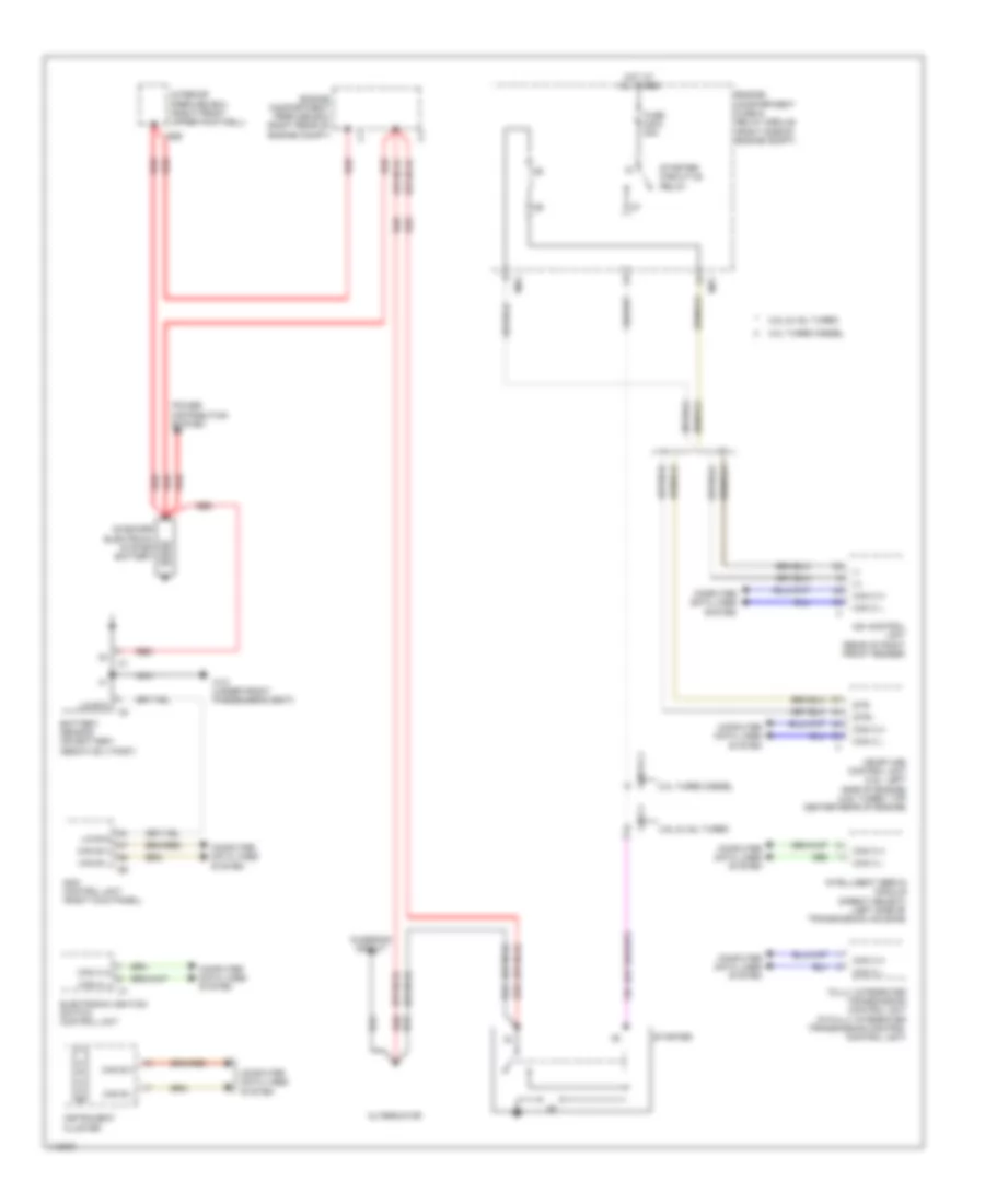
Ground Distribution Wiring Diagram (1 of 2) for Mercedes-Benz ML350 2014
List of elements for Ground Distribution Wiring Diagram (1 of 2) for Mercedes-Benz ML350 2014:
- & lane keeping assist), overhead control panel control unit, panoramic sliding roof control module (w/ panoramic sliding sunroof) sliding roof control module (w/ glass electric sliding roof) & ata (edw)/towing sensor/interior motion sensor control unit (if equipped)
- 360 degree camera control unit (if equipped), driver seat control unit, video & radar sensor system control unit, airmatic control unit (if equipped), telematics can voltage distributor electrical connector, night view assist control unit (if equipped), active roll stabilization control unit (if equipped), electric brake control electrical connector (w/ trailer hitch), left front illuminated door sill molding (w/ interior lights package), sound system amplifier control unit (w/ sound system), left rear display, tv digital turner (if equipped), left front door control unit, left running board courtesy light, satellite digital audio radio (sdar) control unit (w/ sirius satellite radio) & digital audio broadcasting control unit (w/ digital radio)
- Glove box lamp switch
- Glow output stage (3.0l turbo diesel), ignition coil cylinders 1, 2, 3, 4, 5, 6, 7 & 8 (4.6l turbo) & ignition coil cylinders 1, 2, 3, 4, 5 & 6 (3.5l)
- Left 3rd seat row folding backrest switch (left 2nd seat row) (gl-class), right 3rd seat row folding backrest switch (right 2nd seat row) (gl-class), center rear seat belt buckle switch (gl-class), left 2nd seat row easy entry/exit switch (gl class & w/ rear seat belt status indication), left rear seat belt buckle switch (gl-class), keyless go control unit (if equipped), left front reversible emergency tensioning retractor, left rear door control unit, stationary heater radio remote control receiver (if equipped), parking system control unit (w/ parktronic), emergency call system control unit, cellular telephone system antenna amplifier/compensator (w/ comfort telephony) & external navigation electrical connector & telematics services communication module (w/ live traffic information)
- Mobile phone contact plate (w/ comport telephony), audio/comand control panel, media interface control unit (if equipped), fuel filter w/ heating element condensation sensor (3.0l turbo diesel), lower control panel control unit (w/ on-road/off-road package & airmatic), off-road operating panel control unit (if equipped), dvd player (if equipped), cup holder connecting point (if equipped), left second seat row socket, right second seat row socket, front cigarette lighter w/ ashtray illumination (w/ tacho graph preinstallation), illuminated cup holder separation point (w/ interior lights package), comand control unit (if equipped) front center console illumination & digital tachograph control unit (if equipped)
- Right rear display, driver side bag squib, potential distributor electrical connector (can i), vehicle floor chassis can e1 potential distributor electrical connector, right exhaust gas recirculation hall sensor (w/ gasoline direct injection & stratified charge), left exhaust gas recirculation hall sensor (w/ gasoline direct injection & stratified charge), front passenger seat control unit, soot particulate sensor control unit (3.0l turbo diesel), collision prevention assist controller unit, nox sensor control unit downstream of diesel particulate filter (3.0l turbo diesel), nox sensor control unit downstream of scr catalytic converter (3.0l turbo diesel), right potential distributor electrical connector (can), drive train can voltage distributor electrical connector, vehicle floor chassis can e2 potential distributor electrical connector, transfer case control unit (w/ on-road/off-road package), front passenger sidebag squib, right front door control unit, left front bumper distronic sensor (dtr), right front bumper distronic sensor (dtr), right front illuminated door sill molding (w/ interior lights package), eco start/stop function diode (if equipped), me-sfi (me) control unit (3.5l), right running board courtesy light, fuel tank pressure & temperature sensor (4.6l turbo), pressure sensor downstream of air filter (4.6l turbo), pressure sensor downstream of throttle valve (4.6l turbo), pressure sensor upstream of throttle valve (4.6l turbo), crankshaft hall sensor (4.6l turbo), pressure sensor downstream of air filter (4.6l turbo), coolant temperature sensor (3.5l), intake air temperature sensor (3.5l), intake manifold intake air temperature sensor (3.5l), right intake camshaft hall sensor (3.5l), left intake camshaft hall sensor (3.5l), right exhaust camshaft hall sensor (3.5l), right nox sensor control unit (3.5l), left nox sensor control unit (3.5l), left oxygen sensor downstream of catalytic converter (3.5l), right oxygen sensor downstream of catalytic converter (3.5l) & left exhaust camshaft hall sensor (except 3.ol turbo diesel)
- Sam control unit, multi-function camera (w/ traffic sign recognition
- Steering column module control unit (w/ automatic lane recognition, active lane keep assist & steering wheel heater), ac housing (if equipped), upper control panel control unit, automatic air conditioning control & operating unit (if equipped), left/right center air outlet symbol illumination (w/ interior lights package), left/right front side air outlet symbol illumination (w/ interior lights package), driver side instrument panel ambiance illumination (w/ interior lights package), passenger side instrument panel ambiance illumination (w/ interior lights package), left/right front footwell lamp, electric parking brake switch, instrument cluster, diagnostic connector, electronic ignition switch control unit, audio/comand display (if equipped), booster blower electronic blower controller (w/ comfort automatic air conditioning) &
- W1/4 (under center console)
- W11
- W11/2 (3.5l) (right rear of engine compt)
- W12 (under rear of center console)
- W15/1 (right front footwell)
- W15/2 (left front footwell)
- W17/1 (under left seat of 2nd row)
- W18/5 (base of right "a" pillar)
- W26 (under front of center console)
- W7 (base of right "d" pillar)
Ground Distribution Wiring Diagram (2 of 2) for Mercedes-Benz ML350 2014
List of elements for Ground Distribution Wiring Diagram (2 of 2) for Mercedes-Benz ML350 2014:
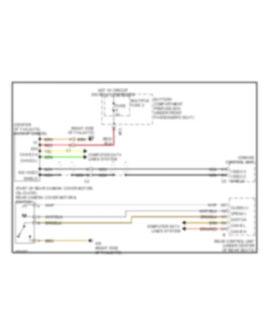
- (under front passenger seat)
- Additional battery (w/o eco start/stop function) & eco start/stop function additional battery (w/ eco start/stop function)
- Backup camera (if equipped), external tailgate operation switch (gl-class), rear camera cover motor, tailgate ambient lamp, inner left rear lamp unit, center stop lamp, inner right rear lamp unit, left liftgate license plate lamp, right liftgate license plate lamp, tailgate wiper motor & tailgate central locking motor
- Battery sensor
- Electrical power steering control unit
- Electronic stability program control unit
- Fan motor
- Intake port shutoff actuator motor, ignition coil cylinders 1, 2, 3, 4, 5, 6, 7 & 8 (4.6l turbo), ignition coil cylinders 1, 2 , 3, 4, 5 & 6 (3.5l), low-temperature circuit shutoff valve (3.5l), direct select intelligent servo module (except 3.0l turbo diesel), fully integrated transmission control unit (except 3.0l turbo diesel), engine compartment fuse & relay module, alarm siren (if equipped), right front brake wear sensor, headlamp control unit (w/ xenon headlamps), left fog lamp,
- Left 3rd seat row folding backrest switch (right 2nd seat row), electric parking brake control unit, rear control unit, right front reversible emergency tensioning retractor, telematics can voltage distributor electrical connector (gl-class), rear fuse box (gl-class), left 3rd seat row backrest release unit (if equipped), right 3rd seat row folding backrest switch, right 2nd seat row), right rear seat belt buckle switch (gl-class), right 2nd seat row easy entry/exit switch (gl-class), right rear door control unit (gl-class), left rear sidebag squib (if equipped) & right rear sidebag squib (if equipped)
- Left rear lamp unit, left pop-out window, anti-pinch protection contact strip (gl-class), load compartment lamp (gl-class), multi-contour seat pneumatic pump (gl-glass), sound system amplifier control unit (w/ extended sound system), bass speaker amplifier (w/ extended sound system), left rear bumper radar sensor (w/ active blind spot assist), left rear bumper intelligent radar sensor (w/ blind spot assist), right rear bumper radar sensor (w/ active blind spot assist), right rear bumper intelligent radar sensor (w/ blind spot assist), rear air conditioning electronic blower controller (if equipped) & load compartment socket (gl-class)
- Nca
- Ptc heater booster (if equipped)
- Rear window heater
- Rear window wave trap
- Stationary heater control unit (if equipped), stationary heater switchover valve (if equipped), headlamp cleaning system pump (if equipped), coolant circulation pump (if equipped), wiper park heater, spray nozzle hose heater (if equipped), wiper motor & left front lamp unit
- Tire pressure monitor control unit, electric parking brake control unit, right rear door control unit (ml-class), stationary heater fuel pump (if equipped), fuel quality sensor (except 3.0l turbo diesel), fuel pump control unit, dc/ac converter control unit (w/ 115v socket), right rear brake wear sensor, left 3rd row seat belt buckle switch (gl-class), right 3rd row seat belt buckle switch (gl-class), right 3rd seat row backrest release unit (gl-class), eco start/stop function additional battery relay (gl-class), telematics can voltage distributor electrical connector (ml-class & w/ rear seat belt buckles), left rear seat belt buckle switch (ml-class & w/ rear seat belt buckles), center rear seat belt buckle switch (ml-class & w/ rear seat belt buckles) & right rear seat belt buckle switch (ml-class & w/ rear seat belt buckles)
- Trailer socket
- Transmission oil auxiliary pump control unit (except 3.0l turbo diesel), me-sfi (me) control unit (except 3.0l turbo diesel), cdi control unit (3.0l turbo diesel), intake port shutoff hall sensor (3.0l turbo diesel) & boost pressure control pressure transducer (3.0l turbo diesel)
- Transmission oil auxiliary pump control unit, coolant run-on pump, charge air cooler circulation pump (4.6l turbo) airmatic compressor (if equipped), fully integrated transmission control control unit (3.0l turbo diesel), direct select intelligent servo module (3.0l turbo diesel), left engine hood contact switch (w/ anti-theft alarm system) & (w/ eco start/stop function), right engine hood contact switch (w/ eco start/stop function), distronic electric controller unit, (w/ active blind spot assist & w/ distronic plus), left fanfare horn (if equipped), right fanfare horn (if equipped), right front lamp unit, right fog lamp, right daytime running headlamps & left daytime running headlamps
- W10
- W10/15 (right rear of luggage compt)
- W15/9 (under center console)
- W17 (under right seat of 2nd row)
- W17/6 (under right seat of 2nd row)
- W2 (right side of engine compt)
- W2/1 (in right front wheelwell)
- W29/8 (left "d" pillar)
- W29/9 (right "d" pillar)
- W30/4 (right front of engine compt)
- W52/11 (right rear of engine compt)
- W6 (at left "d" pillar)
- W7/9 (right side of luggage compt)
- W70 (left front of engine compt)
- W8 (right side of tailgate)
- W8/1 (top left side of tailgate)
- W8/2 (top right side of tailgate)
- W9 (left front of engine compt)
HEADLIGHTS
Headlights Wiring Diagram, with Xenon Lamps (1 of 2) for Mercedes-Benz ML350 2014
List of elements for Headlights Wiring Diagram, with Xenon Lamps (1 of 2) for Mercedes-Benz ML350 2014:
- (base of right "a" pillar) w18/5
- (if equipped)
- 30 l
- 30 r
- 30g
- 49a l
- 49a r
- 56b l
- 56b r
- 57 l
- 57 r
- 58d
- Battery compartment prefuse box (under front passenger's seat)
- Can b h
- Can b l
- Can e1 h
- Can e1 l
- Combination switch
- Computer data lines system
- Engine compartment fuse & relay module (right side of engine compt)
- Exterior lights switch
- Front fog lamp button
- Fuse 15a
- Fuse 30a
- Fuse 40a
- Fuse 5a
- Fuse 7.5a
- Headlamp flasher/ high beam switch
- Hot at all times
- Hot w/ circuit 15 relay energized
- Illumination switch
- Interior prefuse box (right front upper footwell)
- Lds1
- Lds2
- Lds3
- Left active curve illumination actuator motor
- Left front exterior lights led actuation module
- Left front lamp unit
- Left headlamp range adjustment actuator motor
- Left infrared lamp
- Left light distribution actuator motor
- Left xenon bulb w/ integrated ignition module
- Lin b13
- Low beam switch
- Night view assist button
- Nsi l
- Overhead control panel control module
- Pwr1
- Rain/light sensor (top center of windshield)
- Rear fog lamp button
- Rear fuse box (in right rear footwell)
- Right active curve illumination actuator motor
- Right front exterior lights led actuation module
- Right front lamp unit
- Right headlamp range adjustment actuator motor
- Right infrared lamp
- Right light distribution actuator motor
- Right xenon bulb w/ integrated ignition module
- Sam control unit (right kick panel)
- Steering column module control unit (behind steering wheel)
- Tfl l
- Tfl r
- Uh1
- Uh2
- W52/11 (right rear of engine compt)
- W9 (left front of engine compt)
- X18-c1
Headlights Wiring Diagram, with Xenon Lamps (2 of 2) for Mercedes-Benz ML350 2014
List of elements for Headlights Wiring Diagram, with Xenon Lamps (2 of 2) for Mercedes-Benz ML350 2014:
- (right side of engine compt) w2
- +5v
- 30-l
- 30-r
- Can b h
- Can b l
- Can e2 h
- Can e2 l
- Computer data lines system
- Electric parking brake control unit (under right rear seat)
- Electric parking brake switch
- Headlamp control unit (left rear of engine compt)
- High beam indicator lamp
- Inner left rear lamp unit
- Inner right rear lamp unit
- Instrument cluster
- Interior lights system
- Left daytime running lamps headlamp
- Left rear fog lamp
- Lin g1
- Lin g2
- Low beam indicator lamp
- Rear fog lamp indicator lamp
- Right daytime running lamps headlamp
- Right front level sensor (on right front axle suspension)
- Right rear fog lamp
- Right rear level sensor (on right rear axle suspension)
- Sig
- Sw-1
- Sw-2
- Sw-3
- Sw-4
- W1/4 (under center console)
- W17 (under right seat of 2nd row)
- W52/11 (right rear of engine compt)
- W8 (right side of tailgate)
- X18-c1
- X25/2-c1
- X26/32
Headlights Wiring Diagram, without Xenon Lamps (1 of 2) for Mercedes-Benz ML350 2014
List of elements for Headlights Wiring Diagram, without Xenon Lamps (1 of 2) for Mercedes-Benz ML350 2014:
- (base of right "a" pillar) w18/5
- 30g
- 55 l
- 55 r
- 56a l
- 56a r
- 56b l
- 56b r
- 58d
- Can b h
- Can b l
- Can e1 h
- Can e1 l
- Can e2 h
- Can e2 l
- Combination switch
- Computer
- Computer data lines system
- Data lines
- Exterior lights switch
- Fuse 40a
- Fuse 5a
- Headlamp flasher/ high beam switch
- Headlamp range controller
- High beam indicator lamp
- Hot at all times
- Hot w/ circuit 15 relay energized
- Illumination switch
- Instrument cluster
- Interior prefuse box (right front upper footwell)
- Lds1
- Lds2
- Lds3
- Left daytime running lamps headlamp
- Left fog lamp
- Lin b13
- Low beam indicator lamp
- Low beam switch
- Lwr
- Nsi l
- Overhead control panel control module
- Pwr1
- Rain/light sensor (top center of windshield)
- Rear fog lamp button
- Rear fog lamp indicator lamp
- Rear fuse box (in right rear footwell)
- Right daytime running lamps headlamp
- Right fog lamp
- Sam control unit (right kick panel)
- Steering column module control unit (behind steering wheel)
- System
- Tfl l
- Tfl r
- Uh1
- Uh2
- W2 (right side of engine compt)
- W52/11 (right rear of engine compt)
- X18-c1
- X26/32
Headlights Wiring Diagram, without Xenon Lamps (2 of 2) for Mercedes-Benz ML350 2014
List of elements for Headlights Wiring Diagram, without Xenon Lamps (2 of 2) for Mercedes-Benz ML350 2014:
- 30-l
- 30-r
- Battery compartment prefuse box (under front passenger's seat)
- Can e2 h
- Can e2 l
- Computer data lines system
- Electric parking brake control unit (under right rear seat)
- Electric parking brake switch
- Engine compartment fuse & relay module (right side of engine compt)
- Fuse 30a
- Fuse 7.5a
- Hot at all times
- Hot w/ circuit 15 relay energized
- Inner left rear lamp unit
- Inner right rear lamp unit
- Interior lights system
- Left front lamp unit
- Left headlamp range adjustment actuator motor
- Left high beam
- Left low beam
- Left rear fog lamp
- Right front lamp unit
- Right headlamp range adjustment actuator motor
- Right high beam
- Right low beam
- Right rear fog lamp
- Sw-1
- Sw-2
- Sw-3
- Sw-4
- W1/4 (under center console)
- W17 (under right seat of 2nd row)
- W52/11 (right rear of engine compt)
- W8 (right side of tailgate)
- W9 (left front of engine compt)
- X18-c1
HORN
Horn Wiring Diagram for Mercedes-Benz ML350 2014
List of elements for Horn Wiring Diagram for Mercedes-Benz ML350 2014:
- (under center console) w1/4
- 30g
- Button
- C20a
- Can b h
- Can b l
- Can-e1 h
- Can-e1 l
- Center horns button
- Clock spring contact (top of steering column)
- Cockpit circuit 30g fuse box (behind right end of dash)
- Computer data lines system
- Engine compartment fuse & relay module (right side of engine compt)
- Fanfare horn relay
- Fuse 15a
- Fuse 5a
- Hot w/ circuit 15 relay energized
- Hot w/ circuit 30g relay energized
- Left fanfare horn (center front of engine compt)
- Left fanfare horn system
- Mr1
- Rel ff
- Right fanfare horn (center front of engine compt)
- Right fanfare horn system
- Sam control unit (right kick panel)
- Steering column module (behind steering wheel)
- Steering wheel electronics (in steering wheel)
- Uh2
- W52/11 (right rear of engine compt)
INSTRUMENT CLUSTER
Collision Avoidance Wiring Diagram for Mercedes-Benz ML350 2014
List of elements for Collision Avoidance Wiring Diagram for Mercedes-Benz ML350 2014:
- (under center console) w1/4
- C12a
- Can-e1 h
- Can-e1 l
- Can-e2 h
- Can-e2 l
- Cockpit circuit 30 fuse box (behind right end of dash)
- Collision prevention assist controller unit (behind center of front grille)
- Collision prevention assist warning lamp
- Computer data lines system
- Fuse 5a
- Hot at all times
- Hot w/ circuit 15 relay energized
- Instrument cluster
- Rear fuse box (in right rear footwell)
- W15/1 (right front footwell)
- X174/1-c1
Instrument Cluster Wiring Diagram (1 of 2) for Mercedes-Benz ML350 2014
List of elements for Instrument Cluster Wiring Diagram (1 of 2) for Mercedes-Benz ML350 2014:
- (-)
- (under right rear seat) electric parking brake control unit
- Anti-lock brake system indicator lamp
- Battery compartment prefuse box (under front passenger's
- Bbv sig
- Bfs
- Brake fluid level switch (on brake fluid reservoir)
- Brake force distribution warning lamp
- Brake system warning lamp
- C12a
- C15a
- Can b h
- Can b l
- Can e1 h
- Can e1 l
- Can e2 h
- Can e2 l
- Can-b h
- Can-b l
- Check engine mil ind
- Cockpit circuit 30 fuse box (behind right end of dash)
- Collision prevention assist warning lamp (w/o distronic plus)
- Computer data lines system
- Coolant level switch (in coolant reservoir)
- Coolant temperature gauge
- Coolant temperature warning lamp
- Distronic warning lamp
- Dr+
- Dr-
- Driver seat belt buckle restraint system switch (in driver seat belt buckle assembly)
- Electric parking brake switch
- Electronic stability program warning lamp
- Engine diagnosis indicator lamp
- Esp/asr off warning lamp
- Fuel level indicator gauge
- Fuel reserve indicator lamp
- Fuse 5a
- Gear indicator (prnd)
- High beam indicator lamp
- Hot at all times
- Hot w/ circuit 30g relay energized
- Instrument cluster
- Interior lights system
- Kws (-)
- Kws sig
- Left turn signal ind lamp
- Lin b12
- Lin b15
- Lines system computer data
- Low beam indicator lamp
- Mf1
- Multi-function display
- Multiple fuse 1
- Parking brake indicator lamp
- Preglow indicator lamp (diesel)
- Pwr1
- Rear fog lamp indicator lamp
- Right turn signal ind lamp
- Sam control unit (right kick panel)
- Seat belt warning lamp
- Seat)
- Speedometer
- Sw 1
- Sw 2
- Sw 3
- Sw 4
- Tachometer
- Tire pressure monitor warning lamp (if equipped)
- Transmission mode display (s)
- Ts (+)
- Ts (-)
- Ts 2
- Uh1
- Uh2
- W1/4 (under center console)
- W18/5 (base of right "a" pillar)
- X18-c1
- X18/3-c1
- X55/3-c1
Instrument Cluster Wiring Diagram (2 of 2) for Mercedes-Benz ML350 2014
List of elements for Instrument Cluster Wiring Diagram (2 of 2) for Mercedes-Benz ML350 2014:
- (ads) button sport comfort/
- (if equipped)
- (w/ on-road/off-road package & airmatic)
- (w/o on-road/off-road package)
- 30g
- Ata (edw) function indicator
- Automatic child seat recognition air bag off indicator lamp
- Button
- Button level
- Button menu off-road on-road/
- Button mode transmission "m"
- Button mode transmission automatic
- Button range low
- Button regulation
- Button regulation speed
- Can b h
- Can b l
- Computer data lines system
- Downhill
- Eco start/ stop function button
- Esp off button
- Hazard warning system button
- Left front heated seat button
- Left front seat ventilation button
- Left fuel tank fuel level indicator fill level sensor (in top of left side of fuel tank)
- Lin b12
- Lin b15
- Lower control panel control unit
- Nca
- Off-road operating panel control unit
- Parking system button
- Program offroad
- Rear control unit (under center of rear seats)
- Right front brake wear sensor (on right front brake assembly)
- Right front heated seat button
- Right front seat ventilation button
- Right fuel tank fuel level indicator fill level sensor (in top of right side of fuel tank)
- Right rear brake wear sensor (on right rear brake assembly)
- Sig
- Speed downhill
- Stationary heater button
- Switch rotary level
- Upper control panel control unit
- Vehicle
- W1/4 (under center console)
- W12 (under rear of center console)
- W17/6 (under right seat of 2nd row)
- W2 (right side of engine compt)
- X29/6-c1
- X62/33-b
- X62/36-c1
Night Vision Wiring Diagram for Mercedes-Benz ML350 2014
List of elements for Night Vision Wiring Diagram for Mercedes-Benz ML350 2014:
- (base of right "a" pillar) w18/5
- (right kick panel) sam control unit
- + cam
- - cam
- 58d
- 87f
- Can e2 h
- Can e2 l
- Comand control unit
- Computer data lines system
- Data-0 h
- Data-0 l
- Data-1 h
- Data-1 l
- Exterior light switch
- Fuse 5a
- Hot w/ circuit 15 relay energized
- Interior lights system
- Lds1
- Lds2
- Lds3
- Lum
- Lwr
- Nca
- Night view assist button
- Night view assist camera (center front of roof)
- Night view assist control unit (left kick panel)
- Pwr1
- Rear fuse box (in right rear footwell)
- Red
- S10
- Shield
- Shield luna
- Stk_h
- Stk_l
- T-1 h
- T-1 l
- W/o xenon headlamp
- W15/2 (left front footwell)
- X18-c1
Overhead Console Wiring Diagram for Mercedes-Benz ML350 2014
List of elements for Overhead Console Wiring Diagram for Mercedes-Benz ML350 2014:
- (+)
- (-)
- 15r
- 30g
- 58d
- Ambient lamp
- Battery compartment prefuse box (under front passenger's seat)
- Comand control unit
- Door locks & anti-theft systems
- Forward automatic dimming mirror light sensor
- Front dome lamp switch
- Fuse 15a
- Fuse 7.5a
- Garage door opener
- Garage door opener button 1
- Garage door opener button 2
- Garage door opener button 3
- Garage door opener indicator lamp
- Gnd
- Hands-free system microphone group
- Hot at all times
- Il2 l
- Il2 r
- Inside rearview mirror
- Inside rearview mirror dimming
- Interior lamp automatic function switch
- Interior lights system
- Interior temperature sensor w/ integrated fan
- Led
- Left front reading lamp switch
- Left reading lamp
- Lin
- Lin b13
- Ll l
- Ll r
- Ll2 l
- Ll2 r
- Ll33 r
- Mic 1 +
- Mic 2 +
- Overhead control panel control unit
- Pnk
- Rain/light sensor (top center of windshield)
- Rear dome lamp switch
- Rearward automatic dimming mirror light sensor
- Red
- Right front reading lamp switch
- Right reading lamp
- Sam control unit (right kick panel)
- Shield
- Sig
- Sliding roof switch
- Vehicle interior humidity & temperature sensor (top center of windshield)
- W18/5 (base of right "a" pillar)
Tachograph Wiring Diagram for Mercedes-Benz ML350 2014
List of elements for Tachograph Wiring Diagram for Mercedes-Benz ML350 2014:
- (+)
- (-)
- (right kick panel) sam control unit
- 58d
- Battery compartment prefuse box (under front passenger's seat)
- Data
- Digital tachograph control unit
- Digital tachograph distance & speed sensor
- Digital tachograph pull-up resistor
- Dzsvl-a
- Electronic stability program control unit (left front of engine compt)
- Ez sig
- Fuse 20a (or 5a)
- Fuse 5a
- Hot at all times
- Hot w/ circuit 15 relay energized
- Interior lights system
- Rear fuse box (in right rear footwell)
- S13
- S27
- W12 (under rear of center console)
- X25/2-c1
- X91/1-c1
INTERIOR LIGHTS
Courtesy Lamps Wiring Diagram (1 of 3) for Mercedes-Benz ML350 2014
List of elements for Courtesy Lamps Wiring Diagram (1 of 3) for Mercedes-Benz ML350 2014:
- (+)
- (-)
- 2nd seat row left dome lamp
- 2nd seat row right dome lamp
- 30g
- 58d
- Ambient lamp
- Battery compartment prefuse box (under front passenger's seat)
- Can b h
- Can b l
- Computer data lines system
- Driver seat control unit (under driver front seat)
- Frl v
- Front dome lamp switch
- Fuse 15a
- Fuse 30a
- Fuse 40a
- Fuse 5a
- Garage door opener
- Garage door opener indicator lamp
- Glove box lamp
- Glove box lamp switch
- Gnd
- Hot at all times
- Hot w/ circuit 15r1 relay energized
- Il2 l
- Il2 r
- Inside rearview mirror
- Interior lamp automatic function switch
- Interior prefuse box (right front upper footwell)
- Ip 1
- Ip 2
- Left front mirror lamp switch
- Left front reading lamp switch
- Left reading lamp
- Left sun visor mirror lamp
- Lin b13
- Ll 3sr
- Ll l
- Ll r
- Ll2 l
- Ll2 r
- Overhead control panel control unit
- Pnk
- Pwr1
- Rear control unit (under center of rear seats)
- Rear dome lamp switch
- Rear fuse box (in right rear footwell)
- Right dome lamp (ml class)
- Right front mirror lamp switch
- Right front reading lamp switch
- Right reading lamp
- Right rear footwell lamp (w/ interior lights package)
- Right sun visor mirror lamp
- Sam control unit (right kick panel)
- Sig
- Tbbel l
- Tbbel r
- W1/4 (under center console)
- W15/2 (left front footwell)
- W17 (under right seat of 2nd row)
- W18/5 (base of right "a" pillar)
- X18-c1
Courtesy Lamps Wiring Diagram (2 of 3) for Mercedes-Benz ML350 2014
List of elements for Courtesy Lamps Wiring Diagram (2 of 3) for Mercedes-Benz ML350 2014:
- (+)
- (-)
- Battery compartment prefuse box (under front passenger's seat)
- Can b h
- Can b l
- Central load compartment dome lamp
- Computer data lines system
- Flat wire
- Front passenger seat control unit (under passenger front seat)
- Fuse 30a
- Hot at all times
- Instrument cluster
- Interior prefuse box (right front upper footwell)
- Left front footwell lamp
- Left front illuminated door sill molding (w/ interior lights package)
- Left front running board courtesy lights
- Left rear footwell lamp (w/ interior lights package)
- Left rear running board courtesy lights
- Left running board courtesy lights (if equipped)
- Multi- function display
- Rain/light sensor (top center of windshield)
- Right front footwell lamp
- Right front running board courtesy lights
- Right rear running board courtesy lights
- Right running board courtesy lights (if equipped)
- Tailgate ambient lamp
- Tailgate external operation switch
- W1/4 (under center console)
- W15/1 (right front footwell)
- W15/2 (left front footwell)
- W8 (right side of tailgate)
- X157/24-c1
- X157/25-c1
Courtesy Lamps Wiring Diagram (3 of 3) for Mercedes-Benz ML350 2014
List of elements for Courtesy Lamps Wiring Diagram (3 of 3) for Mercedes-Benz ML350 2014:
- (in right rear door) right rear door control unit
- (w/ interior lights package) left rear door ambiance illumination
- (w/ interior lights package) right front door ambiance illumination
- (w/ interior lights package) right rear door ambiance illumination
- (w/ interior lights package) right rear door exit & warning lamp
- (w/o power closing doors & trunk lid) left rear door pre-locking position micro switch
- (w/o power closing doors & trunk lid) right front door pre-locking position micro switch
- (w/o power closing doors & trunk lid) right rear door pre-locking position micro switch
- Awl (+)
- Awl (-)
- Can b h
- Can b l
- Computer data lines system
- Driver-side instrument panel ambiance illumination (w/ interior lights package)
- Flat wire
- Left front door ambiance illumination (w/ interior lights package)
- Left front door control unit (in left front door)
- Left front door exit & warning lamp
- Left front door handle illumination
- Left front door lock
- Left front door pre-locking position micro switch (w/o power closing doors & trunk lid)
- Left rear door control unit (in left rear door)
- Left rear door exit & warning lamp (interior lights package)
- Left rear door handle illumination
- Left rear door lock
- Ll bemst
- Ll bnst
- Passenger-side instrument panel ambiance illumination (w/ interior lights package)
- Right front door control unit (in right front door)
- Right front door exit & warning lamp
- Right front door handle illumination
- Right front door lock
- Right front illuminated door sill molding (w/ interior lights package)
- Right rear door handle illumination
- Right rear door lock
- Sig df
- Tib (+)
- Tib (-)
- W/ power closing doors & trunk lid
- W/o power closing doors & trunk lid
- W1/4 (under center console)
- W15/1 (right front footwell)
- W15/2 (left front footwell)
- W17 (gl class) w17/6 (ml class) (under right seat of 2nd row)
- W17/1 (under left seat of 2nd row)
- X157/10-c1
- X157/11-c1
- X157/12-c1
- X157/13
- X157/14-c1
- X157/6-c1
- X157/7-c1
- X157/9-c1
- X18-c1
- X35/1-c1
- X35/2-c1
- X35/3-c1
- X35/4-c1
Instrument Illumination Wiring Diagram (1 of 2) for Mercedes-Benz ML350 2014
List of elements for Instrument Illumination Wiring Diagram (1 of 2) for Mercedes-Benz ML350 2014:
- (if equipped)
- (w/ interior lights package) front center console cupholder illumination
- 30g
- 58d
- Anti-theft alarm system/emergency call system button group
- C20a
- Can b h
- Can b l
- Can e1 h
- Can e1 l
- Cockpit circuit 30g fuse box (behind right end of dash)
- Combination switch
- Computer data lines system
- Exterior lights switch
- Front center console illumination
- Front cigarette lighter w/ ashtray illumination (if equipped)
- Fuse 30a
- Fuse 40a
- Fuse 5a
- Headlamp flasher/ high beam switch
- Hot at all times
- Hot w/ circuit 15 relay energized
- Hot w/ circuit 30g relay energized
- Illuminated cupholder separation point (w/o cupholder & w/ interior lights package)
- Interior prefuse box (right front upper footwell)
- Lds 1
- Lds 2
- Lds 3
- Liftgate control button symbol illumination
- Lin b12
- Lin b13
- Nca
- Overhead control panel control unit
- Pwr1
- Rear control unit (under center of rear seats)
- Rear fuse box (in right rear footwell)
- Sam control unit (right kick panel)
- Steering column module (behind steering wheel)
- Switch illumination
- Tailgate control button
- W1/4 (under center console)
- W12 (under rear of center console)
- W17 (under right seat of 2nd row)
- W18/5 (base of right "a" pillar)
- X18-c1
- X29/6-c1
Instrument Illumination Wiring Diagram (2 of 2) for Mercedes-Benz ML350 2014
List of elements for Instrument Illumination Wiring Diagram (2 of 2) for Mercedes-Benz ML350 2014:
- (-)
- (left front footwell) w15/2
- (under center console) w1/4
- (w/ interior lights package)
- 30g
- 58d
- Automatic transmission mode button
- Battery compartment prefuse box (under front passenger's seat)
- Can b h
- Can b l
- Computer data lines system
- Driver trunk lid/ liftgate control button
- Electrical parking brake switch
- Fuse 30a
- Fuse 5a
- Hot at all times
- Hot w/ circuit 30g relay energized
- Interior prefuse box (right front upper footwell)
- Left center air outlet symbol illumination
- Left front door central locking interior switch
- Left front door control unit (in left front door)
- Left front side air outlet symbol illumination
- Left rear door control unit (in left rear door)
- Left rear power window switch
- Lin b12
- Lower control panel control unit
- Mf1
- Multiple fuse 1
- Passenger side power window switch
- Red
- Right center air outlet symbol illumination
- Right front door central locking interior switch
- Right front door control unit (in right front door)
- Right front side air outlet symbol illumination
- Right rear door control unit (in right rear door)
- Right rear power window switch
- Sig
- W1/4 (under center console)
- W12 (under rear of center console)
- W15/1 (right front footwell)
- W17 (gl class) w17/6 (ml class) (under right seat of 2nd row)
- W17/1 (under left seat of 2nd row)
- X29/6-c1
- X35/1-c1
- X35/2-c1
- X35/3-c1
- X35/4-c1
MEMORY SYSTEMS
Driver"s Memory Seat Wiring Diagram (1 of 2) for Mercedes-Benz ML350 2014
List of elements for Driver"s Memory Seat Wiring Diagram (1 of 2) for Mercedes-Benz ML350 2014:
- (+)
- (-)
- (right kick panel) sam control unit
- 12v
- 12v (+)
- 30g
- Can b h
- Can b l
- Computer data lines system
- Driver massage function control unit (in driver front seat back)
- Driver multicontour seat control unit (in driver front seat back)
- Driver seat backrest inclination adjustment motor & hall sensor
- Driver seat control unit (under driver front seat)
- Driver seat head restraint adjustment motor & hall sensor
- Driver seat lumbar support adjustment control unit (under driver front seat)
- Driver seat lumbar support adjustment switch
- Driver seat lumbar support pneumatic pump
- Fds l (-)
- Fds l 30g
- Ffrbel
- Fuse 30a
- Fuse 7.5a
- Hot at all times
- Hot w/ circuit 30g relay energized
- Hs (+)
- Hs (-)
- K mot
- Ks hs sig
- L hs(+)
- L hs(-)
- L mot(+)
- L mot(-)
- Lin
- Mls h
- Mls v
- Nca
- Pnk
- Rear fuse box (in right rear footwell)
- Red
- Seats system
- Sig
- W/ massage function
- W/o massage function
- W15/2 (left front footwell)
Driver"s Memory Seat Wiring Diagram (2 of 2) for Mercedes-Benz ML350 2014
List of elements for Driver"s Memory Seat Wiring Diagram (2 of 2) for Mercedes-Benz ML350 2014:
- (+)
- (-)
- Can b h
- Can b l
- Computer data lines system
- Driver seat control unit (under driver front seat)
- Driver seat fore/aft adjustment motor & hall sensor
- Driver seat height adjustment motor & hall sensor
- Driver seat inclination adjustment motor & hall sensor
- Fuse 30a
- Hot at all times
- Hv hs (+)
- Hv mot (+)
- Hv mot (-)
- Hv nv hs(-)
- Interior lights system
- Interior prefuse box (right front upper footwell)
- Left front door control module (in left front door)
- Left front seat adjustment switch group
- Lin b5
- Lv hs (+)
- Lv mot (+)
- Lv mot (-)
- Nv hs (+)
- Nv mot (+)
- Nv mot (-)
- Seats system
- Steering column in/out adjustment motor & hall sensor (steering column in/out adjustment motor: on steering column) (hall sensor: part of steering column in/out adjustment motor)
- Steering column up/down adjustment motor & hall sensor (steering column up/down adjustment motor: on steering column) (hall sensor: part of steering column up/down adjustment motor)
- W15/2 (left front footwell)
- X18-c1
- X35/1-c1
Memory Mirrors Wiring Diagram for Mercedes-Benz ML350 2014
List of elements for Memory Mirrors Wiring Diagram for Mercedes-Benz ML350 2014:
- (+)
- (in left front door) left front door control module
- (in right front door) right front door control module
- (right front footwell) w15/1
- Automatic dimming mirror (if equipped)
- Battery compartment prefuse box (under front passenger's seat)
- Can b h
- Can b l
- Can-b h
- Can-b l
- Computer data lines system
- Driver side power window & outside mirror adjustment switch group
- Fuse 30a
- Horizontal inclination adjustment actuator motor
- Horizontal inclination adjustment potentiometer
- Hot at all times
- Interior prefuse box (right front upper footwell)
- Led
- Led 31
- Left blind spot assist readiness & warning indicator (if equipped)
- Left front seat adjustment switch group
- Left outside mirror
- Left outside mirror adjustment switch
- Left outside mirror ambient lamp
- Left outside mirror turn signal lamp
- Lin b5
- Lin b6
- Mirror heater
- Nca
- Outside mirror adjustment switch
- Outside mirror fold-in/fold-out electric motor (if equipped)
- Outside mirror fold-in/fold-out switch
- Right blind spot assist readiness & warning indicator (if equipped)
- Right front seat adjustment switch group
- Right outside mirror
- Right outside mirror adjustment switch
- Right outside mirror ambient lamp
- Right outside mirror turn signal lamp
- Sh (+) 61
- Sh (-) 31
- Sig
- Sv m1
- Sv m1m2
- Sv m2
- Vertical inclination adjustment actuator motor
- Vertical inclination adjustment potentiometer
- W15/2 (left front footwell)
- X35/1-c1
- X35/2-c1
Passenger"s Memory Seat Wiring Diagram (1 of 2) for Mercedes-Benz ML350 2014
List of elements for Passenger"s Memory Seat Wiring Diagram (1 of 2) for Mercedes-Benz ML350 2014:
- (+)
- (-)
- (right kick panel) sam control unit
- 12v
- 12v (+)
- 30g
- Battery compartment prefuse box (under front passenger's seat)
- Can b h
- Can b l
- Computer data lines system
- Fds l (-)
- Fds l 30g
- Ffrbel
- Front passenger massage function control unit (in front passenger seat back)
- Front passenger multicontour seat control unit (in front passenger seat back)
- Front passenger seat backrest inclination adjustment motor & hall sensor
- Front passenger seat control unit (under passenger front seat)
- Front passenger seat head restraint adjustment motor & hall sensor
- Front passenger seat lumbar support adjustment control unit (under passenger front seat)
- Front passenger seat lumbar support adjustment switch
- Front passenger seat lumbar support pneumatic pump
- Fuse 30a
- Fuse 7.5a
- Hot at all times
- Hot w/ circuit 30g relay energized
- K mot
- Ks hs sig
- L hs (+)
- L hs (-)
- L mot (+)
- L mot (-)
- Lin
- Nca
- Pnk
- Rear fuse box (in right rear footwell)
- Red
- Seats system
- Sig
- W/ massage function
- W/o massage function
- W15/1 (right front footwell)
Passenger"s Memory Seat Wiring Diagram (2 of 2) for Mercedes-Benz ML350 2014
List of elements for Passenger"s Memory Seat Wiring Diagram (2 of 2) for Mercedes-Benz ML350 2014:
- (+)
- (-)
- Can b h
- Can b l
- Computer data lines system
- Front passenger seat control unit (under front passenger front seat)
- Front passenger seat fore/aft adjustment motor & hall sensor
- Front passenger seat height adjustment motor & hall sensor
- Front passenger seat inclination adjustment motor & hall sensor
- Hv hs (+)
- Hv mot (+)
- Hv mot (-)
- Hv nv hs(-)
- Interior lights system
- Lin b6
- Lv hs (+)
- Lv mot (+)
- Lv mot (-)
- Nv hs (+)
- Nv mot (+)
- Nv mot (-)
- Right front door control module (in right front door)
- Right front seat adjustment switch group
- Seats system
- W15/1 (right front footwell)
- X35/2-c1
Steering Column Memory Wiring Diagram for Mercedes-Benz ML350 2014
List of elements for Steering Column Memory Wiring Diagram for Mercedes-Benz ML350 2014:
- (in left front door) left front door control module
- (left front footwell) w15/2
- 30g
- C20a
- Can b h
- Can b l
- Can e1 h
- Can e1 l
- Cockpit circuit 30g fuse box (behind right end of dash)
- Computer data lines system
- Driver seat control unit (under driver front seat)
- Fuse 30a
- Fuse 30a s4
- Fuse 5a
- Fuse 7.5a
- Hot at all times
- Hot w/ circuit 30g relay energized
- Hs (+)
- Hs (-)
- Interior prefuse box (right front upper footwell)
- Left front seat adjustment switch group
- Lin b5
- Mls h
- Mls v
- Rear fuse box (in right rear footwell)
- Steering column adjustment & steering wheel heater switch
- Steering column adjustment switch
- Steering column in/out adjustment motor & hall sensor (steering column in/out adjustment motor: on steering column) (hall sensor: part of steering column in/out adjustment motor)
- Steering column module (behind steering wheel)
- Steering column up/down adjustment motor & hall sensor (steering column up/down adjustment motor: on steering column) (hall sensor: part of steering column up/down adjustment motor)
- W1/4 (under center console)
- W15/2 (left front footwell)
- X18-c1
- X35/1-c1
NAVIGATION
All Around Vision Camera Wiring Diagram for Mercedes-Benz ML350 2014
List of elements for All Around Vision Camera Wiring Diagram for Mercedes-Benz ML350 2014:
- (center of front bumper) front end 360 degree camera
- 30g
- 360 degree camera control unit (under driver's seat)
- Battery compartment prefuse box (under front passenger's seat)
- Can e2 h
- Can e2 l
- Comand control unit
- Computer data lines system
- Fuse 5a
- Hot w/ circuit 30g relay energized
- Left outside mirror 360 degree camera (in left rearview mirror)
- Mf2
- Multiple fuse 2
- Nca
- Rear end 360 degree camera (left rear fender)
- Right outside mirror 360 degree camera (in right rearview mirror)
- Rx+
- Rx-
- Shield
- W15/2 (left front footwell)
- X174/1-c3
- X35/1-c2
- X35/2-c2
Blind Spot Information System Wiring Diagram for Mercedes-Benz ML350 2014
List of elements for Blind Spot Information System Wiring Diagram for Mercedes-Benz ML350 2014:
- (at left "d" pillar)
- (left front footwell) w15/2
- (right front footwell) w15/1
- Battery compartment prefuse box (under front passenger's seat)
- C13
- Can e1 h
- Can e1 l
- Can-b h
- Can-b l
- Can-e1 h
- Can-e1 l
- Computer data lines system
- Fuse 30a
- Fuse 5a
- Hot at all times
- Hot w/ circuit 15 relay energized
- Interior prefuse box (right front footwell)
- Led
- Led 31
- Left blind spot assist readiness & warning indicator (if equipped)
- Left front door control module (in left front door)
- Left outside mirror
- Left rear bumper radar sensor (behind left end of rear bumper)
- Nca
- Rear fuse box (in right rear footwell)
- Right blind spot assist readiness & warning indicator (if equipped)
- Right front door control module (in right front door)
- Right outside mirror
- Right rear bumper radar sensor (behind right end of rear bumper)
- Vehicle floor chassis can e1 potential distributor electrical connector
- X35/1-c1
- X35/2-c1
- X35/29-c1
COMAND Actuation Wiring Diagram (1 of 4) for Mercedes-Benz ML350 2014
List of elements for COMAND Actuation Wiring Diagram (1 of 4) for Mercedes-Benz ML350 2014:
- (+)
- (-)
- (pins: 1 to 8 not used)
- (under rear of center console)
- 30g
- 30z
- Am antenna
- Anst
- Ant
- Aux jack electrical connector
- Aux1 gnd
- Aux1 l
- Aux1 r
- Aux1 shield
- Aux2 o gnd
- Aux2 o l
- Aux2 o r
- Aux2 o s
- Battery compartment prefuse box (under front passenger's seat)
- C12
- C14
- Can a h
- Can a l
- Can-b h
- Can-b l
- Comand control unit
- Computer data lines system
- Connector
- Diag
- Electronic ignition switch control unit
- Fm 1, am, cl (zv) & keyless go antenna amplifier (top right side of tailgate)
- Fm antenna
- Fm1/am
- Fuse 30a
- Fuse 5a
- Gnd
- Hot at all times
- Hot w/ circuit 30g relay energized
- In 2 gnd
- In 2 l
- In 2 r
- In 2 shield
- Keyless go control module (under left rear seat)
- Mic 1+
- Mic 2+
- Most data bus circuit
- Mute
- Nca
- Out (+)
- Out (-)
- Out 1 gnd
- Out 1 l
- Out 1 r
- Out 1 shield
- Pnk
- Rear fuse box (in right rear footwell)
- Rear spoiler antenna (integral to rear spoiler antenna)
- Red
- Shield
- Sig
- Sig shield
- Usb d +
- Usb d -
- Usb electrical
- Usb v-bus
- W/ keyless go
- W/o keyless go
- W12
- Wake up
- X18-c1
COMAND Actuation Wiring Diagram (2 of 4) for Mercedes-Benz ML350 2014
List of elements for COMAND Actuation Wiring Diagram (2 of 4) for Mercedes-Benz ML350 2014:
- "back" button
- "delete" button
- (behind left center of dash) comand fan motor
- (left side of luggage compt floor) emergency call system control unit
- 30g
- Audio/ comand controller
- Audio/comand control panel
- Can-a h
- Can-a l
- Computer data lines system
- Dvd player
- Headphones electrical connector (cabled) (w/ split view)
- Left free programming button
- Left front door speaker
- Left front door tweeter
- Left rear door speaker
- Left rear door tweeter
- Nca
- Pnk
- Red
- Right free programming button
- Right front door speaker
- Right front door tweeter
- Right rear door speaker
- Right rear door tweeter
- W/o sound system
- W12 (under rear of center console)
- X29/6-c1
- X35/1-c1
- X35/2-c1
- X35/3-c1
- X35/4-c1
COMAND Actuation Wiring Diagram (3 of 4) for Mercedes-Benz ML350 2014
List of elements for COMAND Actuation Wiring Diagram (3 of 4) for Mercedes-Benz ML350 2014:
- "back" & voice control system off button
- (in steering wheel) steering wheel electronics
- (left front footwell) w15/2
- 30g
- Accept/ terminate phone call button
- Ant
- Battery compartment prefuse box (under front passenger's seat)
- Buttons + & - for setting specific functions & volume control
- Dab
- Digital audio broadcasting control unit (under driver's seat)
- Fm 2, dab & tv 1 antenna amplifier (top left side of tailgate)
- Fuse 5a
- Gnd
- Group
- Handsfree system microphone
- Hot w/ circuit 30g relay energized
- Inside rearview mirror
- L, ok
- Left multi-function steering wheel button group
- Lin e1
- Mf1
- Mf2
- Most
- Most data bus circuit
- Most in
- Most out
- Multiple fuse 1
- Multiple fuse 2
- Mute button
- Mute, sbs
- Nca
- Ok button
- Pnk
- R, return
- Right multi-function steering wheel button group
- Scroll forward/back button
- Shield
- System selection button
- Tel
- Tv 1 antenna amplifier (w/ tv tuner (digital)) (right side of tailgate)
- U mfl l
- U mfl r
- Up/dwn
- Voice control system on button
- W/ tv tuner
- W/o tv tuner
- Wake up
COMAND Actuation Wiring Diagram (4 of 4) for Mercedes-Benz ML350 2014
List of elements for COMAND Actuation Wiring Diagram (4 of 4) for Mercedes-Benz ML350 2014:
- (or nca)
- 21a
- 30g
- 360 degree camera control unit (under driver's seat)
- Ant bt
- Ant gps
- Audio/comand display
- Backup camera (center of tailgate)
- C13
- C20
- C20a
- Can-a h
- Can-a l
- Can-e1 h
- Can-e1 l
- Clock spring contact (top of steering column)
- Cockpit circuit 30g fuse box (behind right end of dash)
- Comand control unit
- Computer data lines system
- Fuse 5a
- Global positioning system antenna splitter (w/ navigation) (center of luggage compt)
- Gnd
- Gps
- Hot w/ circuit 30g relay energized
- Lum
- Lvds tx +
- Lvds tx -
- Lvds tx+
- Lvds tx-
- Media interface electrical connector
- Most data bus circuit
- Most in
- Most out
- Multi-function antenna
- Nca
- Night view assist control unit (if equipped) (left kick panel)
- Res
- S1 shield luna
- Shield
- Steering column module control unit (behind steering wheel)
- Telematics services communication module
- Ucl shield
- Ucl sig
- V bus
- Video c
- Video c shield
- W/ 360 degree camera
- W/ backup camera
- W1/4 (under center console)
- X1-gps
- X29/6-c4
Emergency Call Wiring Diagram for Mercedes-Benz ML350 2014
List of elements for Emergency Call Wiring Diagram for Mercedes-Benz ML350 2014:
- (+)
- (-)
- (under left seat of 2nd row)
- A out crash
- Ant not
- Antgps
- Battery compartment prefuse box (under front passenger's seat)
- Can-d h
- Can-d l
- Center instrument panel speaker
- Comand actuation circuit
- Comand control unit
- Computer data lines system
- Crash
- Emergency call system antenna (under right rear of luggage compt floor)
- Emergency call system control unit (left side of luggage compt floor)
- Fuse 5a
- Global positioning system antenna splitter (center of luggage compt)
- Gps
- Gps antenna
- Hot at all times
- Mic (+)
- Mic (-)
- Multi-function antenna
- Mute
- Nca
- Not
- Shield
- Sig
- Sound system amplifier control unit (behind right rear seat)
- Sound systems
- Tel
- Tele phone antenna
- W/ advanced sound system
- W/ comman control
- W/o advanced sound system
- W/o comman control
- W17/1
- X18-c1
- X26/4-c1
Multifunction Camera Wiring Diagram for Mercedes-Benz ML350 2014
List of elements for Multifunction Camera Wiring Diagram for Mercedes-Benz ML350 2014:
- (base of right "a" pillar) w18/5
- 30g
- Auxiliary heater heating element (center front of roof)
- Battery compartment prefuse box (under front passenger's seat)
- Can e2 h
- Can e2 l
- Computer data lines system
- Defrost+
- Defrost-
- Fuse 5a
- Hot w/ circuit 30g relay energized
- Lvds n
- Lvds p
- Mf2
- Multi-function camera (center front of roof)
- Multiple fuse 2
- Nca
- Nca s
- Shield
- Video & radar sensor system control unit (w/ active lane keeping assist) (left kick panel)
- Video n
- Video p
Parktronic Wiring Diagram for Mercedes-Benz ML350 2014
List of elements for Parktronic Wiring Diagram for Mercedes-Benz ML350 2014:
- (+) sh
- (+) sv
- (-) sh
- (-) sv
- 30g
- Battery compartment prefuse box (under front passenger's seat)
- Can e2 h
- Can e2 l
- Center left front parking system distance sensor (behind front bumper)
- Center right front parking system distance sensor (behind front bumper)
- Computer data lines system
- Front parking system warning indicator
- Fuse 5a
- Hot w/ circuit 30g relay energized
- Inner left front parking system distance sensor (behind front bumper)
- Inner left rear parking system distance sensor (behind rear bumper)
- Inner right front parking system distance sensor (behind front bumper)
- Inner right rear parking system distance sensor (behind rear bumper)
- Lin b15
- Mf1
- Multiple fuse 1
- Outer left front parking system distance sensor (behind front bumper)
- Outer left rear parking system distance sensor (behind rear bumper)
- Outer right front parking system distance sensor (behind front bumper)
- Outer right rear parking system distance sensor (behind rear bumper)
- Parking system button
- Parking system control unit (under left rear seat)
- Pnk
- Rear parking system warning indicator
- S1 v
- S10 h
- S2 v
- S3 v
- S4 v
- S5 v
- S6 v
- S7 h
- S8 h
- S9 h
- Upper control panel control unit
- W17/1 (under left seat of 2nd row)
- Wh (+)
- Wh(-)
- Wh(data)
- Wv (+)
- Wv (-)
- Wv(data)
- X174/1-c1
- X18-c1
- X18/2-c1
- X26/4-c1
- X35/28-c1
Rear Camera Wiring Diagram for Mercedes-Benz ML350 2014
List of elements for Rear Camera Wiring Diagram for Mercedes-Benz ML350 2014:
- (center of tailgate) backup camera
- (part of rear camera cover motor) (gl-class) rear camera cover motor & switch
- (right side of tailgate) w8
- 30g
- Battery compartment prefuse box (under front passenger's seat)
- Can b h
- Can b l
- Can e2 h
- Can e2 l
- Close(+)
- Comand control unit
- Computer data lines system
- Fuse 5a
- Hot w/ circuit 30g relay energized
- Mf2
- Multiple fuse 2
- Nca
- Open(+)
- Rear control unit (under center of rear seats)
- Red
- S1 video c shield c5
- Shield
- Sig video
- Switch
- Video c
- W8 (right side of tailgate)
POWER DISTRIBUTION
Power Distribution Wiring Diagram (1 of 4) for Mercedes-Benz ML350 2014
List of elements for Power Distribution Wiring Diagram (1 of 4) for Mercedes-Benz ML350 2014:
- (if equipped)
- (not used)
- (right front upper footwell) interior prefuse box
- (right rear of engine compt) engine compartment prefuse box
- (under front passenger's seat) battery compartment prefuse box
- 85a
- 85b
- 86a
- 86b
- Ac housing
- Airmatic control unit
- Ata (edw)/ towing sensor/ interior motion sensor control unit
- Audio/ comand control panel
- Battery sensor
- C4 red
- Circuit 30g relay
- Digital tachograph control unit
- E2b
- Eco start/ stop function diode (if equipped)
- Eco start/stop function diode (if equipped)
- Electric parking brake control unit
- Electrical power steering control unit
- Electronic stability program control unit
- Emergency call system control unit
- Fan motor
- Fm1, am, cl (zv) & keyless go antenna amplifier
- Fuse
- Fuse 100a
- Fuse 10a
- Fuse 125a
- Fuse 150a
- Fuse 15a
- Fuse 200a
- Fuse 25a
- Fuse 30a
- Fuse 400a
- Fuse 40a
- Fuse 5a
- Fuse 7.5a
- Fuse n/a
- Fuse pyro fuse n/a
- K88
- Keyless go control unit (if equipped)
- Left front door control unit
- Left front reversible emergency tensioning retractor
- Left rear door control unit
- Lower control panel control unit & (w/ on-road/ off-road package & airmatic) off road operating panel control unit (w/ on-road/ off-road package)
- Mf1
- Multi-contour seat pneumatic pump (if equipped)
- Multiple fuse 1
- On-board electrical system battery
- Overhead control panel control unit
- Panoramic sliding roof control module (w/ panoramic sliding roof) sliding roof control module (w/ glass electric sliding roof)
- Parking system control unit (if equipped)
- Ptc heater booster (if equipped)
- Pwr1
- Pwr2
- Rear air conditioning electronic blower controller (if equipped)
- Rear control unit (gl class)
- Rear control unit (w/ rear seat heaters)
- Red
- Right front door control unit
- Right front reversible emergency tensioning retractor
- Right rear door control unit
- S10
- S12
- S13
- S14
- S15
- S16
- S17
- S18
- S22
- S27
- Sam control unit
- Sound system amplifier control unit (sound system) bass speaker amplifier (w/ extended sound system)
- Sound system amplifier control unit (w/ extended sound system)
- Sound system amplifier control unit (w/ sound system)
- To cockpit circuit 30 fuse box (diagram 2 of 4)
- To cockpit circuit 30g fuse box (diagram 3 of 4)
- To engine compartment fuse & relay module (diagram 2 of 4)
- To engine compartment fuse & relay module (diagram 3 of 4)
- To multiple fuse 2 (diagram 3 of 4)
- To rear fuse box (diagram 3 of 4)
- To rear fuse box (diagram 4 of 4)
- Transfer case control unit (on-road/ off-road package)
- X18-c2
- X25/2-c2
Power Distribution Wiring Diagram (2 of 4) for Mercedes-Benz ML350 2014
List of elements for Power Distribution Wiring Diagram (2 of 4) for Mercedes-Benz ML350 2014:
- (behind right end of dash) cockpit circuit 30 fuse box
- (in right rear footwell) rear fuse box
- (not used)
- (right side of engine compt) engine compartment fuse & relay module
- 10a
- 115v ac1
- 115v ac2
- 115v socket
- 3.0l turbo diesel
- 30z
- Active roll stabilization control unit (if equipped)
- Additional battery
- Booster blower electronic blower controller (w/ comfort automatic air conditioning)
- Buffer battery fuse (right rear of luggage compt)
- C10a
- C11a
- C12a
- C13a
- C14a
- C15a
- C16a
- C17a
- C18a
- C5e
- Can a h
- Can a l
- Can b h
- Can b l
- Can d h
- Can d l
- Can e2 h
- Can e2 l
- Circuit 15r1 relay
- Circuit 87m relay
- Computer data lines system
- Dc/ac converter control unit (under left rear seat)
- Diagnostic connector
- Direct select intelligent servo module
- Eco start/stop function additional battery
- Eco start/stop function additional battery relay (if equipped) (near eco start/stop function additional battery)
- Electronic ignition switch control unit
- Except 3.0l turbo diesel
- Fm1, am, cl (zv) & keyless go antenna amplifier
- From battery compartment prefuse box (diagram 1 of 4)
- From circuit 15 relay (diagram 4 of 4)
- From circuit 15r2 socket relay (diagram 4 of 4)
- From rear fuse box (diagram 4 0f 4)
- From rear fuse box (diagram 4 of 4)
- From rear fuse box j (diagram 4 0f 4)
- Front passenger seat occupied recognition, acsr (if equipped) & weight sensing system (wss) control unit (if equipped)
- Fuse 10a
- Fuse 15a
- Fuse 5a
- Fuse 7.5a
- Fuse n/a
- Glove box lamp
- Instrument cluster
- Left front door control unit
- Me-sfi (me) control unit
- Mr2
- Nca
- Not 2
- Pb 30b
- Pnk
- Rear window wiper relay
- Red
- Sam control unit
- Socket micro switch
- Steering column module control unit
- System control unit
- Tk ft
- Upper control panel control unit
- W/ eco star/stop function
- W/o eco star/stop function
- W1/4 (under center console)
- W10/15 (right rear of luggage compt)
- W17/6 (under right seat of 2nd row)
- W7 (ml class) w17 (gl class) (ml class: base of right "d" pillar) (gl class: under right seat of 2nd row)
- X18-c1
- X22/2-c1
- X22/2-c2
- X25/2-c1
- X35/1
Power Distribution Wiring Diagram (3 of 4) for Mercedes-Benz ML350 2014
List of elements for Power Distribution Wiring Diagram (3 of 4) for Mercedes-Benz ML350 2014:
- (behind right end of dash) cockpit circuit 30g fuse box
- (in right rear footwell) rear fuse box
- (not used)
- (right side of engine compt) engine compartment fuse & relay module
- (under front passenger's seat) battery compartment prefuse box
- (w/ eco start/ stop function)
- (w/ rear seat heaters)
- 360 degree camera control unit & backup camera (if equipped)
- Airmatic relay (if equipped)
- Alarm siren (w/ anti-theft alarm system)
- Audio/ comand display (w/ comand)
- Automatic air conditioning control & operating unit (if equipped)
- Backup relay
- C19a
- C20a
- C20e
- C21a
- C22a
- Circuit
- Circuit 15 relay (unlatched)
- Comand control unit (if equipped)
- Coolant run-on pump relay
- Direct select intelligent servo module
- Distronic electric control unit (w/ distronic plus & active blind spot assist)
- Driver seat control unit
- Dvd player (w/ rear entertainment)
- Electronic stability program control unit
- Fanfare horn relay
- From battery compartment prefuse box (diagram 1 of 4)
- From engine compartment prefuse box (diagram 1 of 4)
- From multiple fuse 1 c (diagram 1 of 4)
- Front passenger seat control unit
- Fully integrated transmission control unit & transmission oil auxiliary pump control unit (w/ eco start/ stop function)
- Fuse 10a
- Fuse 15a
- Fuse 20a
- Fuse 240a 30a
- Fuse 240b 30a
- Fuse 25a
- Fuse 30a
- Fuse 40a
- Fuse 5a
- Fuse 7.5a
- Fuse n/a
- Headlamp control unit (w/ xenon headlamps)
- Left front lamp unit
- Left rear display (if equipped)
- Media interface control unit (if equipped)
- Mf2
- Mf3
- Mf4
- Mr1
- Mr2
- Multifunction camera (if equipped)
- Multiple fuse 2
- Multiple fuse 3
- Multiple fuse 4
- Pnk
- Rcp (hbf) control unit
- Red
- Relay
- Right front lamp unit
- Right rear display (if equipped)
- S12
- S13
- S14
- S21
- Sam control unit
- Satellite digital audio radio control unit (sirius satellite radio) & digital audio broadcasting control unit (digital radio)
- Starter circuit 50 relay
- Stationary heater unit (if equipped)
- Steering column module control unit
- Tailgate control unit
- Tire pressure monitor control unit (if equipped)
- Trailer recognition control unit (w/ trailer hitch)
- Turbo- charger relay
- Uh2
- Video & radar sensor system control unit (if equipped)
- W2 (right side of engine compt)
- Windshield wiper on/off relay
- Wiper level 1/2 relay
- Wiper park position heater relay
Power Distribution Wiring Diagram (4 of 4) for Mercedes-Benz ML350 2014
List of elements for Power Distribution Wiring Diagram (4 of 4) for Mercedes-Benz ML350 2014:
- (in right rear footwell) rear fuse box
- (not used)
- (under rear of center console)
- 15r1
- Backup relay
- Circuit 15r2 socket relay
- Circuit relay
- Comand control unit (if equipped)
- Cup holder
- Cup holder button
- Cup holder illumination
- Digital tachograph control unit (if equipped)
- Distronic sensor/ left front bumper, distronic sensor/ right front bumper, right rear bumper intelligent radar sensor (w/ blind spot assist), left rear bumper intelligent radar sensor (w/ blind spot assist), left rear bumper radar sensor & right rear bumper radar sensor (w/ active blind spot assit)
- Driver seat control unit
- E1a
- E1b
- Electric brake control electric connector (w/ trailer hitch)
- Electric parking brake control unit
- Exterior lights switch
- From interior prefuse box (diagram 1 of 4)
- Front cigar lighter w/ ashtray illumination
- Front passenger seat control unit
- Fuel pump control unit
- Fuel quality sensor (if equipped)
- Fuse 10a
- Fuse 15a
- Fuse 20a
- Fuse 25a
- Fuse 30a
- Fuse 40a
- Fuse 5a
- Fuse 7.5a
- Fuse n/a
- Heated rear window relay
- Interior lights system
- Left 2nd seat row release unit (w/ electric easy entry)
- Left second seat row socket & right second seat row socket
- Load compartment socket
- Nca
- Night view assist control unit (if equipped)
- Pas (gas) control unit
- Pnk
- Rear control unit
- Rear window wiper relay
- Red
- Residual heat ind lamp
- Right 2nd seat row release unit (w/ electric easy entry)
- S10
- S11
- S12
- S13
- S14
- S18
- S19
- S20
- Sam control unit
- Special vehicle multi-function control unit (svmcu (mss))
- Stationary heater radio remote control receiver (if equipped)
- Tailgate control unit
- Tailgate wiper motor
- To circuit 15r1 relay (diagram 2 of 4)
- To dc/ac converter control unit (diagram 2 of 4)
- To eco start/ stop function additional battery relay (diagram 2 of 4)
- To socket micro switch (diagram 2 of 4)
- Trailer recognition control unit
- Transfer case control unit (on-road/ off road package)
- W12
- W12 (under rear of center console)
- W7 (base of right "d" pillar)
- X29/6-c1
POWER DOOR LOCKS
Automatic Door Locks Wiring Diagram (1 of 3) for Mercedes-Benz ML350 2014
List of elements for Automatic Door Locks Wiring Diagram (1 of 3) for Mercedes-Benz ML350 2014:
- (integral to driver's outside door handle) driver door infrared remote control receiver
- (right front footwell) w15/1
- +5v
- 58d
- Battery compartment prefuse box (under front passenger's seat)
- Can b h
- Can b l
- Central locking motor
- Computer data lines system
- Data
- Driver side power window & outside mirror adjustment switch group
- Fuse 30a
- Fuse 40a
- Hot at all times
- Interior prefuse box (right front upper footwell)
- Left front door control module (in left front door)
- Left front door lock
- Left front door power closing actuator motor (w/ power closing for doors and trunk lid)
- Lin b5
- Mks art sig
- Mks-abh
- Mks-atr-sig
- Mks-ibh
- Mks-jbh
- Mks-vr-sig
- Pre-locking position micro switch
- Rear side window child safety lock switch
- Right front door central locking interior switch
- Right front door control module (in right front door)
- Right front door lock
- Right front door power closing actuator motor (w/ power closing for doors & trunk lid)
- Sec mot c
- Sec mot rs
- Ses mot c
- Ses mot rs
- Sig
- Sig-df
- W/ power closing for doors & trunk lid
- W/o power closing for doors & trunk lid
- W15/2 (left front footwell)
- X35/1-c1
- X35/2-c1
- Zv-c
- Zv-o
Automatic Door Locks Wiring Diagram (2 of 3) for Mercedes-Benz ML350 2014
List of elements for Automatic Door Locks Wiring Diagram (2 of 3) for Mercedes-Benz ML350 2014:
- (+)
- (base of right "a" pillar) w18/5
- (under right seat of 2nd row) w17
- 58d
- Can b h
- Can b l
- Can e2 h
- Can e2 l
- Can-b h
- Can-b l
- Central motor locking
- Computer data lines system
- Doors & trunk lid
- Instrument cluster
- Left front door central locking interior switch
- Left rear door control module (in left rear door)
- Left rear door lock
- Left rear door power closing actuator motor (w/ power closing for doors & trunk lid)
- Liftgate locking pawl switch
- Mks abh
- Mks atr sig
- Mks ibh
- Mks vr sig
- Multi-function display
- Pre-locking position micro switch
- Pwr1
- Rear control unit (under center of rear seats)
- Rotary tumbler switch
- Sam control unit (right kick panel)
- Ses mot c
- Ses mot rs
- Sig
- Sig df
- Tailgate central locking motor
- Tailgate control button
- Tank cap central locking actuator
- W/ power closing for
- W/o power closing for
- W17/1 (under left seat of 2nd row)
- W7 (base of right "d" pillar)
- W8 (right side of tailgate)
- X35/3-c1
- Zv-c
- Zv-o
Automatic Door Locks Wiring Diagram (3 of 3) for Mercedes-Benz ML350 2014
List of elements for Automatic Door Locks Wiring Diagram (3 of 3) for Mercedes-Benz ML350 2014:
- (base of right "a" pillar) w18/5
- 58d
- Anti-theft alarm system/emergency call system button group (if equipped)
- Ata (edw) function indicator
- Ata (edw)/towing sensor/interior motion sensor control unit (in roof console)
- Battery compartment prefuse box (under front passenger's seat)
- Bus
- Can b h
- Can b l
- Central locking motor
- Computer data lines system
- Doors & trunk lid
- Fuse 15a
- Fuse 30a
- Fuse 5a
- Hot at all times
- Led
- Lin
- Lin b 13
- Mks abh
- Mks ibh
- Mks vr sig
- Mks-atr-sig
- Overhead control panel control unit
- Pre-locking position position micro switch
- Rear fuse box (in right rear footwell)
- Red
- Right rear door control module (in right rear door)
- Right rear door lock
- Right rear door power closing actuator motor (w/ power closing for doors & trunk lid)
- Ses-mot-c
- Ses-mot-rs
- Sig
- Sig df
- Upper control panel control unit
- W/ power closing for
- W/o power closing for
- W17/6 (ml class) w17 (gl class) (under right seat of 2nd row)
- W18/5 (base of right "a" pillar)
- X35/4-c1
- Zv-c
- Zv-o
Keyless Go System Wiring Diagram for Mercedes-Benz ML350 2014
List of elements for Keyless Go System Wiring Diagram for Mercedes-Benz ML350 2014:
- (under left seat of 2nd row) w17/1
- Ant
- Battery compartment prefuse box (under front passenger's seat)
- Can b h
- Can b l
- Can-b h
- Can-b l
- Center console keyless-go antenna (under middle of center console)
- Computer data lines system
- Fm 1, am, cl (zv) & keyless go antenna amplifier (top right side of tailgate)
- Fuse 15a
- Gnd
- Hot at all times
- Instrument cluster
- Keyless go control unit (under left rear seat)
- Left front keyless go door handle (in outside door handle)
- Left rear door keyless go antenna (upper front of left rear door)
- Left rear keyless go door handle (in outside door handle)
- Multi-function display
- Nca
- Right front keyless go door handle (in outside door handle)
- Right rear door keyless go antenna (upper front of right rear door)
- Right rear keyless go door handle (in outside door handle)
- Sig
- Vehicle interior keyless go antenna (under front of center console)
- X29/6-c2
- X35/1-c1
- X35/2-c1
- X35/3-c1
- X35/4-c1
- X8/34-c1
- X8/35-c1
- X8/36-c1
- X8/37-c1
POWER MIRRORS
Automatic Day/Night Mirror Wiring Diagram for Mercedes-Benz ML350 2014
List of elements for Automatic Day/Night Mirror Wiring Diagram for Mercedes-Benz ML350 2014:
- (left front footwell) w15/2
- (right front footwell) w15/1
- 15r
- 30g
- 58d
- Ambient lamp
- Automatic dimming mirror
- Battery compartment prefuse box (under front passenger's seat)
- Can b h
- Can b l
- Computer data lines system
- Forward automatic dimming mirror light sensor
- Fuse 15a
- Fuse 30a
- Garage door opener
- Garage door opener button
- Garage door opener indicator lamp
- Hands-free system microphone group
- Hot at all times
- Inside rearview mirror
- Inside rearview mirror dimming
- Interior prefuse box (right front upper footwell)
- Left front door control module (in left front door)
- Left outside mirror
- Left reading lamp
- Lin b13
- Ll l
- Ll r
- Navigation system
- Nca
- Overhead control panel control unit
- Pnk
- Rain/light sensor (top center of windshield)
- Rearward automatic dimming mirror light sensor
- Right front door control module (in right front door)
- Right reading lamp
- Sig
- W18/5 (base of right "a" pillar)
- X35/1-c1
- X35/2-c1
Power Mirror Wiring Diagram for Mercedes-Benz ML350 2014
List of elements for Power Mirror Wiring Diagram for Mercedes-Benz ML350 2014:
- (+)
- Automatic dimming mirror (if equipped)
- Battery compartment prefuse box (under front passenger's seat)
- Can-b h
- Can-b l
- Computer data lines system
- Driver-side power window & outside mirror adjustment switch group
- Fuse 30a
- Horizontal inclination adjustment actuator motor
- Hot at all times
- Interior prefuse box (right front upper footwell)
- Led
- Led 31
- Left blind- spot assist readiness & warning indicator (if equipped)
- Left front door control module (in left front door)
- Left front power window switch
- Left outside mirror
- Left outside mirror adjustment switch
- Left outside mirror ambient lamp
- Left outside mirror turn signal lamp
- Left rear power window switch
- Lin b5
- Mirror heater
- Nca
- Outside mirror adjustment switch
- Outside mirror fold-in/ fold-out electric motor (if equipped)
- Outside mirror fold-in/ fold-out switch (if equipped)
- Rear side window child safety lock switch
- Right blind- spot assist readiness & warning indicator (if equipped)
- Right front door control unit (in right front door)
- Right front power window switch
- Right outside mirror
- Right outside mirror adjustment switch
- Right outside mirror ambient lamp
- Right outside mirror turn signal lamp
- Right rear power window switch
- Sh(+) 61
- Sh(-) 31
- Sig
- Sv m1
- Sv m1 m2
- Sv m2
- Veritical inclination adjustment actuator motor
- W15/1 (right front footwell)
- W15/2 (left front footwell)
- X35/1-c1
- X35/2-c1
POWER SEATS
Front Ventilation & Heated Seat Wiring Diagram (1 of 2) for Mercedes-Benz ML350 2014
List of elements for Front Ventilation & Heated Seat Wiring Diagram (1 of 2) for Mercedes-Benz ML350 2014:
- (+)
- (-)
- 30g
- Can b h
- Can b l
- Computer data lines system
- Driver seat control unit (under driver front seat)
- Fuse 30a
- Fuse 7.5a
- Hot at all times
- Hot w/ circuit 30g relay energized
- Left front backrest heated cushion
- Left front backrest seat ventilation motors
- Left front seat cushion seat ventilation motors
- Left front seat sitting surface heated cushion
- Nca
- Pnk
- Rear fuse box (in right rear footwell)
- W15/2 (left front footwell)
Front Ventilation & Heated Seat Wiring Diagram (2 of 2) for Mercedes-Benz ML350 2014
List of elements for Front Ventilation & Heated Seat Wiring Diagram (2 of 2) for Mercedes-Benz ML350 2014:
- (+)
- (-)
- 30g
- C15a
- Can b h
- Can b l
- Cockpit circuit 30 fuse box (behind right end of dash)
- Computer data lines system
- Front passenger seat control unit (under passenger front seat)
- Fuse 5a
- Hot at all times
- Left front heated seat button
- Left front seat ventilation button
- Lin b15
- Nca
- Pnk
- Right front backrest heated cushion
- Right front backrest seat ventilation motors
- Right front heated seat button
- Right front seat cushion seat ventilation motors
- Right front seat sitting surface heated cushion
- Right front seat ventilation button
- Upper control panel control unit
- W1/4 (under center console)
- W15/1 (right front footwell)
Heated Steering Wheel Wiring Diagram for Mercedes-Benz ML350 2014
List of elements for Heated Steering Wheel Wiring Diagram for Mercedes-Benz ML350 2014:
- 30g
- C20a
- Can e1 h
- Can e1 l
- Clock spring contact (top of steering column)
- Cockpit circuit 30g fuse box (behind right end of dash)
- Computer data lines system
- Fuse 5a
- Heating element
- Heating element temperature sensor
- Hot w/ circuit 30g relay energized
- Lin e1
- Nca
- Ntc+
- Ntc-
- Steering column adjustment & steering wheel heater switch
- Steering column adjustment switch
- Steering column module (behind steering wheel)
- Steering wheel electronics (in steering wheel)
- Steering wheel heater
- Steering wheel heater indicator lamp (if equipped)
- Steering wheel heater switch (if equipped)
- W/ steering wheel heater automatic lane recognition & lane keeping assist
- W1/4 (under center console)
Rear Folding Seat Wiring Diagram (1 of 2) for Mercedes-Benz ML350 2014
List of elements for Rear Folding Seat Wiring Diagram (1 of 2) for Mercedes-Benz ML350 2014:
- Battery compartment prefuse box (under front passenger's seat)
- Center 2nd seat row head restraint motor (w/ electric easy-entry)
- Fuse 10a
- Fuse 30a
- Hot at all times
- Left 2nd seat row easy entry/exit switch
- Left 2nd seat row head restraint motor (w/ electric easy-entry)
- Left 2nd seat row release unit (w/ electric easy-entry) (in left 2nd row seat back)
- Left 3rd seat row folding backrest motor
- Nca
- Out +
- Rear control unit (under center of rear seats)
- Rear fuse box (in right rear footwell)
- Right 2nd seat row easy entry/exit switch
- Right 2nd seat row head restraint motor (w/ electric easy-entry)
- Right 2nd seat row release unit (w/ electric easy-entry) (in right 2nd row seat back)
- Right 3rd seat row folding backrest motor
- Sig in
- W17 (under right seat of 2nd row)
- W17/1 (under left seat of 2nd row)
- X55/5-c4
- X55/5-c5
- X55/6-c4
Rear Folding Seat Wiring Diagram (2 of 2) for Mercedes-Benz ML350 2014
List of elements for Rear Folding Seat Wiring Diagram (2 of 2) for Mercedes-Benz ML350 2014:
- (base of right "d" pillar) w7
- In +
- Left 2nd seat row folding backrest switch (w/ electric easy-entry)
- Left 3rd seat row backrest release unit (left outer seat back pivot assembly)
- Left 3rd seat row folding backrest switch (left 2nd seat row)
- Left 3rd seat row folding backrest switch (load compartment)
- Left 3rd seat row folding backrest switch (right 2nd seat row)
- Out +
- Rear control unit (under center of rear seats)
- Right 2nd seat row folding backrest switch (w/ electric easy-entry)
- Right 3rd seat row backrest release unit (right outer seat back pivot assembly)
- Right 3rd seat row folding backrest switch (left 2nd seat row)
- Right 3rd seat row folding backrest switch (load compartment)
- Right 3rd seat row folding backrest switch (right 2nd seat row)
- Sam control unit (w/ electric easy-entry) (right kick panel)
- Sig in
- W17 (under right seat of 2nd row)
- W17/1 (under left seat of 2nd row)
- W17/6 (under right seat of 2nd row)
- X55/21-c2
- X55/22-c1
- X55/5-c5
- X55/6-c5
Rear Heated Seats Wiring Diagram for Mercedes-Benz ML350 2014
List of elements for Rear Heated Seats Wiring Diagram for Mercedes-Benz ML350 2014:
- (+)
- 2nd seat row left rear seat heater button (if equipped)
- 2nd seat row right rear seat heater button (if equipped)
- 30g
- Battery compartment prefuse box (under front passenger's seat)
- Can-b h
- Can-b l
- Computer data lines system
- Fuse 30a
- Fuse 5a
- Hot at all times
- Hot w/ circuit 30g relay energized
- Left rear backrest heated cushion
- Left rear seat sitting surface heated cushion
- Mf2
- Multiple fuse 2
- Nca
- Rcp (hbf) control unit
- Rear control unit (under center of rear seats)
- Rear fuse box (in right rear footwell)
- Right rear backrest heater pad
- Right rear seat sitting surface heated cushion
- W12 (under rear of center console)
- W17 (under right seat of 2nd row)
- X29/6-c2
- X55/5-c1
- X55/5-c3
- X55/6-c1
- X55/6-c3
POWER TOP/SUNROOF
Panoramic Roof Wiring Diagram for Mercedes-Benz ML350 2014
List of elements for Panoramic Roof Wiring Diagram for Mercedes-Benz ML350 2014:
- 30g
- Anst
- Battery compartment prefuse box (under front passenger's seat)
- Can-b h
- Can-b l
- Computer data lines system
- Fuse 30a
- Hot w/ circuit 30g relay energized
- Hs 1
- Hs 2
- Nca
- Panoramic sliding roof control module (center front of roof)
- Panoramic sliding roof control unit
- Panoramic sliding roof hall sensor 1
- Panoramic sliding roof hall sensor 2
- Panoramic sliding roof motor
- Panoramic sliding roof roller sun blind drive unit (center front of roof)
- Sensor 1 hall
- Sensor 2 hall
- Sun blind motor
- W18/5 (base of right "a" pillar)
- X133/2-c2
Power Sliding Roof Wiring Diagram for Mercedes-Benz ML350 2014
List of elements for Power Sliding Roof Wiring Diagram for Mercedes-Benz ML350 2014:
- 30g
- Battery compartment prefuse box (under front passenger's seat)
- Can-b h
- Can-b l
- Computer data lines system
- Fuse 15a
- Fuse 30a
- Fuse 7.5a
- Hot at all times
- Hot w/ circuit 30g relay energized
- Lin b13
- Overhead control panel control unit
- Sam control unit (right kick panel)
- Sliding roof control module (center front of roof)
- Sliding roof hall sensor 1
- Sliding roof hall sensor 2
- Sliding roof motor
- Sliding roof switch
- W18/5 (base of right "a" pillar)
POWER WINDOWS
Power Windows Wiring Diagram for Mercedes-Benz ML350 2014
List of elements for Power Windows Wiring Diagram for Mercedes-Benz ML350 2014:
- (-)
- (in left front door)
- (under left seat of 2nd row) w17/1
- (under right seat of 2nd row) (gl-class) w17 (ml-class) w17/6
- (under right seat of 2nd row) w17
- 58d
- Afs (-)
- Afs-50d
- Afs-cldse
- Afs-open
- Battery compartment prefuse box (under front passenger's seat)
- Can b h
- Can b l
- Computer data lines system
- Driver side power window & outside mirror adjustment switch group
- Fh h
- Fh t
- Fhs deep
- Fhs up
- Fuse 30a
- H (+)
- H (-)
- Hot at all times
- Hs (+)
- Hs (-)
- Hs 1
- Interior prefuse box (right front upper footwell)
- Left front door control module
- Left front power window motor
- Left front power window switch
- Left pop-out window anti-pinch protection contact strip (gl-class) (in left "c" pillar)
- Left rear door control module (in left rear door)
- Left rear power window motor
- Left rear power window switch
- Left vent window motor (gl-class) (in left "d" pillar)
- Lin b5
- Nca
- Out
- Passenger side power window switch
- Rear control unit (under center of rear seats)
- Rear fuse box (in right rear footwell)
- Rear side window child safety lock switch
- Right front door control module (in right front door)
- Right front power window motor
- Right front power window switch
- Right pop-out window anti-pinch protection contact strip (gl-class) (in right "c" pillar)
- Right rear door control module (in right rear door)
- Right rear power window motor
- Right rear power window switch
- Right vent window motor (gl-class) (in right "d" pillar)
- Sig
- Vent window switch (gl-class)
- W15/1 (right front footwell)
- W15/2 (left front footwell)
- W6 (at left "d" pillar)
- W7 (base of right "d" pillar)
- X35/1-c1
- X35/2-c1
- X35/3-c1
- X35/4-c1
RADIO
COMAND Actuation Wiring Diagram (1 of 4) for Mercedes-Benz ML350 2014
List of elements for COMAND Actuation Wiring Diagram (1 of 4) for Mercedes-Benz ML350 2014:
- (+)
- (-)
- (pins: 1 to 8 not used)
- (under rear of center console)
- 30g
- 30z
- Am antenna
- Anst
- Ant
- Aux jack electrical connector
- Aux1 gnd
- Aux1 l
- Aux1 r
- Aux1 shield
- Aux2 o gnd
- Aux2 o l
- Aux2 o r
- Aux2 o s
- Battery compartment prefuse box (under front passenger's seat)
- C12
- C14
- Can a h
- Can a l
- Can-b h
- Can-b l
- Comand control unit
- Computer data lines system
- Connector
- Diag
- Electronic ignition switch control unit
- Fm 1, am, cl (zv) & keyless go antenna amplifier (top right side of tailgate)
- Fm antenna
- Fm1/am
- Fuse 30a
- Fuse 5a
- Gnd
- Hot at all times
- Hot w/ circuit 30g relay energized
- In 2 gnd
- In 2 l
- In 2 r
- In 2 shield
- Keyless go control module (under left rear seat)
- Mic 1+
- Mic 2+
- Most data bus circuit
- Mute
- Nca
- Out (+)
- Out (-)
- Out 1 gnd
- Out 1 l
- Out 1 r
- Out 1 shield
- Pnk
- Rear fuse box (in right rear footwell)
- Rear spoiler antenna (integral to rear spoiler antenna)
- Red
- Shield
- Sig
- Sig shield
- Usb d +
- Usb d -
- Usb electrical
- Usb v-bus
- W/ keyless go
- W/o keyless go
- W12
- Wake up
- X18-c1
COMAND Actuation Wiring Diagram (2 of 4) for Mercedes-Benz ML350 2014
List of elements for COMAND Actuation Wiring Diagram (2 of 4) for Mercedes-Benz ML350 2014:
- "back" button
- "delete" button
- (behind left center of dash) comand fan motor
- (left side of luggage compt floor) emergency call system control unit
- 30g
- Audio/ comand controller
- Audio/comand control panel
- Can-a h
- Can-a l
- Computer data lines system
- Dvd player
- Headphones electrical connector (cabled) (w/ split view)
- Left free programming button
- Left front door speaker
- Left front door tweeter
- Left rear door speaker
- Left rear door tweeter
- Nca
- Pnk
- Red
- Right free programming button
- Right front door speaker
- Right front door tweeter
- Right rear door speaker
- Right rear door tweeter
- W/o sound system
- W12 (under rear of center console)
- X29/6-c1
- X35/1-c1
- X35/2-c1
- X35/3-c1
- X35/4-c1
COMAND Actuation Wiring Diagram (3 of 4) for Mercedes-Benz ML350 2014
List of elements for COMAND Actuation Wiring Diagram (3 of 4) for Mercedes-Benz ML350 2014:
- "back" & voice control system off button
- (in steering wheel) steering wheel electronics
- (left front footwell) w15/2
- 30g
- Accept/ terminate phone call button
- Ant
- Battery compartment prefuse box (under front passenger's seat)
- Buttons + & - for setting specific functions & volume control
- Dab
- Digital audio broadcasting control unit (under driver's seat)
- Fm 2, dab & tv 1 antenna amplifier (top left side of tailgate)
- Fuse 5a
- Gnd
- Group
- Handsfree system microphone
- Hot w/ circuit 30g relay energized
- Inside rearview mirror
- L, ok
- Left multi-function steering wheel button group
- Lin e1
- Mf1
- Mf2
- Most
- Most data bus circuit
- Most in
- Most out
- Multiple fuse 1
- Multiple fuse 2
- Mute button
- Mute, sbs
- Nca
- Ok button
- Pnk
- R, return
- Right multi-function steering wheel button group
- Scroll forward/back button
- Shield
- System selection button
- Tel
- Tv 1 antenna amplifier (w/ tv tuner (digital)) (right side of tailgate)
- U mfl l
- U mfl r
- Up/dwn
- Voice control system on button
- W/ tv tuner
- W/o tv tuner
- Wake up
COMAND Actuation Wiring Diagram (4 of 4) for Mercedes-Benz ML350 2014
List of elements for COMAND Actuation Wiring Diagram (4 of 4) for Mercedes-Benz ML350 2014:
- (or nca)
- 21a
- 30g
- 360 degree camera control unit (under driver's seat)
- Ant bt
- Ant gps
- Audio/comand display
- Backup camera (center of tailgate)
- C13
- C20
- C20a
- Can-a h
- Can-a l
- Can-e1 h
- Can-e1 l
- Clock spring contact (top of steering column)
- Cockpit circuit 30g fuse box (behind right end of dash)
- Comand control unit
- Computer data lines system
- Fuse 5a
- Global positioning system antenna splitter (w/ navigation) (center of luggage compt)
- Gnd
- Gps
- Hot w/ circuit 30g relay energized
- Lum
- Lvds tx +
- Lvds tx -
- Lvds tx+
- Lvds tx-
- Media interface electrical connector
- Most data bus circuit
- Most in
- Most out
- Multi-function antenna
- Nca
- Night view assist control unit (if equipped) (left kick panel)
- Res
- S1 shield luna
- Shield
- Steering column module control unit (behind steering wheel)
- Telematics services communication module
- Ucl shield
- Ucl sig
- V bus
- Video c
- Video c shield
- W/ 360 degree camera
- W/ backup camera
- W1/4 (under center console)
- X1-gps
- X29/6-c4
DVD Player Wiring Diagram for Mercedes-Benz ML350 2014
List of elements for DVD Player Wiring Diagram for Mercedes-Benz ML350 2014:
- (under rear of center console) w12
- 30g
- Audio gnd
- Audio l
- Audio r
- Audio shield
- Battery compartment prefuse box (under front passenger's seat)
- C12
- Can-a h
- Can-a l
- Comand control unit
- Computer data lines system
- Dvd player
- Fuse 5a
- Hot w/ circuit 30g relay energized
- Left rear display
- Mf3
- Multiple fuse 3
- Nca
- Red
- Right rear display
- Video c
- Video c shield
- Video y
- Video y shield
- W15/1 (right front footwell)
- W15/2 (left front footwell)
- X55/50-c1
- X55/50-c2
- X55/51-c1
- X55/51-c2
MOST Data Bus Wiring Diagram for Mercedes-Benz ML350 2014
List of elements for MOST Data Bus Wiring Diagram for Mercedes-Benz ML350 2014:
- C2a
- Comand control unit
- Media interface control unit (w/ media interface) (left rear of engine compt)
- Most
- Most in
- Most out
- Satellite digital audio radio (sdar) control unit (w/ sirius satellite radio) digital audio broadcasting control unit (w/ digital radio) (under driver's seat)
- Sound system amplifier control unit (w/ sound system) (behind right rear seat)
- W/ advanced sound system
- W/ digital radio
- W/ sirius satellite radio
- W/o advanced sound system
- Wake up
Multimedia Interface Wiring Diagram for Mercedes-Benz ML350 2014
List of elements for Multimedia Interface Wiring Diagram for Mercedes-Benz ML350 2014:
- 30g
- Audio in gnd
- Audio in right
- Audio in shield audio in left
- Battery compartment prefuse box (under front passenger's seat)
- Cable detect
- Comand control unit
- Fuse 5a
- Hot w/ circuit 30g relay energized
- Media interface control unit (left rear of engine compt)
- Media interface electrical connector
- Mf2
- Most
- Most data bus circuit
- Most in
- Most out
- Multiple fuse 2
- Nca
- Red
- Serial gnd
- Serial in (rx)
- Serl out (tx)
- Shield
- Sig
- Usb +5v
- Usb data (+)
- Usb data (-)
- Usb gnd
- W12 (under rear of center console)
- Wake up
- X nca
- X29/6-c4
Satellite Radio Wiring Diagram for Mercedes-Benz ML350 2014
List of elements for Satellite Radio Wiring Diagram for Mercedes-Benz ML350 2014:
- (left front footwell) w15/2
- 30g
- Ant
- Battery compartment prefuse box (under front passenger's seat)
- Fuse 5a
- Hot w/ circuit 30g relay energized
- Mf2
- Most
- Most data bus circuit
- Most in
- Most out
- Multi-function antenna
- Multiple fuse 2
- Nca
- Satellite digital audio radio (sdar) control unit (under driver's seat)
- Shield
- Wake up
Sound Amplifier Wiring Diagram, with Advanced Sound System (1 of 2) for Mercedes-Benz ML350 2014
List of elements for Sound Amplifier Wiring Diagram, with Advanced Sound System (1 of 2) for Mercedes-Benz ML350 2014:
- (+)
- (-)
- (at left "d" pillar) (gl-class, ml-class early production) w6
- (left side of luggage compt floor) emergency call system control unit
- Battery compartment prefuse box (under front passenger's seat)
- Center instrument panel speaker
- Fuse 10a
- Fuse 30a
- Fuse 5a
- Gl-class
- Gnd
- Hot at all times
- Hot w/ circuit 30g relay energized
- Ice-txd
- Icewron
- Ice_rxd
- Left front door midrange speaker
- Left rear door tweeter
- Left rear surround speaker
- Lo_subw+
- Lo_subw-
- Lo_wofl+
- Lo_wofl-
- Lo_wofr+
- Lo_wofr-
- Lo_worl+
- Lo_worl-
- Lo_worr+
- Lo_worr-
- Mf1
- Most data bus circuit
- Most in
- Most out
- Multiple fuse 1
- Nca
- Pnk
- Right front door midrange speaker
- Right rear door tweeter
- Right rear surround speaker
- S10
- S12
- Sound system amplifier control unit (behind right rear seat)
- Sound system amplifier control unit ground line shield
- Sound system microphone (in roof console)
- Telmute
- Twfl +
- Twfl -
- Twfr +
- Twfr -
- W7 (ml-class late production) (base of right "d" pillar)
- Wake up
- X18-c1
- X26/4-c1
- X35/1-c1
- X35/2-c1
- X35/3-c1
- X35/39-c1
- X35/4-c1
- X35/40-c1
- X38/3-c1
- X38/4-c1
Sound Amplifier Wiring Diagram, with Advanced Sound System (2 of 2) for Mercedes-Benz ML350 2014
List of elements for Sound Amplifier Wiring Diagram, with Advanced Sound System (2 of 2) for Mercedes-Benz ML350 2014:
- (+)
- (-)
- (at left "d" pillar) (gl-class, ml-class early production) w6
- (under rear of center console) w12
- 30g
- Audio/comand control panel
- Audio/comand controller
- Back button
- Bass speaker amplifier (behind right rear seat)
- Can a h
- Can a l
- Computer data lines system
- Delete button
- Front lens +
- Front lens -
- Gnd
- Icewron
- Ice_rxd
- Ice_txd
- Left free programming button
- Left front door bass speaker
- Left rear door speaker
- Lens ctrl
- Lo_subw+
- Lo_subw-
- Lo_wofl+
- Lo_wofl-
- Lo_wofr+
- Lo_wofr-
- Lo_worl+
- Lo_worl-
- Lo_worr+
- Lo_worr-
- Mirror triangle left front door speaker
- Mirror triangle right front door speaker
- Rear bass speaker
- Right free programming button
- Right front door bass speaker
- Right rear door speaker
- W7 (ml-class late production) (base of right "d" pillar)
- X29/6-c1
- X35/1-c1
- X35/2-c1
- X35/3-c1
- X35/4-c1
Sound Amplifier Wiring Diagram, without Advanced Sound System for Mercedes-Benz ML350 2014
List of elements for Sound Amplifier Wiring Diagram, without Advanced Sound System for Mercedes-Benz ML350 2014:
- "back" button
- "delete" button
- (+)
- (-)
- 30g
- Audio/ comand controller
- Audio/comand control panel
- Battery compartment prefuse box (under front passenger's seat)
- C2a
- Can dh
- Can dl
- Can-a h
- Can-a l
- Center instrument panel speaker
- Computer data lines system
- Emergency call system control unit (left side of luggage compt floor)
- Fuse 40a
- Fuse 5a
- Gl class
- Hot at all times
- Hot w/ circuit 30g relay energized
- Left free programming button
- Left front door bass speaker
- Left front door midrange speaker
- Left front door sound system tweeter
- Left rear door speaker
- Left rear door tweeter
- Left rear surround speaker
- Mf1
- Most
- Most data bus circuit
- Most in
- Most out
- Multiple fuse 1
- Mute
- Pnk
- Rear bass speaker
- Right free programming button
- Right front door bass speaker
- Right front door midrange speaker
- Right front door sound system tweeter
- Right rear door speaker
- Right rear door tweeter
- Right rear surround speaker
- S12
- Sound system amplifier control unit (behind right rear seat)
- Telmute
- W12 (under rear of center console)
- W15/2 (left front footwell)
- Wake up
- X18-c1
- X26/4-c1
- X29/6-c1
- X35/1-c1
- X35/2-c1
- X35/3-c1
- X35/39-c1
- X35/4-c1
- X35/40-c1
- X38/3-c1
- X38/4-c1
SHIFT INTERLOCK
Shift Interlock Wiring Diagram for Mercedes-Benz ML350 2014
List of elements for Shift Interlock Wiring Diagram for Mercedes-Benz ML350 2014:
- (under center console) w1/4
- 30-l
- 30-r
- Battery compartment prefuse box (under front passenger's seat)
- Can e2 h
- Can e2 l
- Computer data lines system
- Electric parking brake control unit (under right rear seat)
- Electric parking brake switch
- Fuse 30a
- Fuse 5a
- Hot at all times
- Hot w/ circuit 15 relay energized
- Interior lights system
- Left electric parking brake actuator motor (on left rear brake assembly)
- M r-
- M-l+
- M-l-
- M-r+
- Rear fuse box (in right rear footwell)
- Red
- Right electric parking brake actuator motor (on right rear brake assembly)
- Sw-1
- Sw-2
- Sw-3
- Sw-4
- T-m-l
- T-m-r
- W17 (under right seat of 2nd row)
- W17/6 (under right seat of 2nd row)
- X18-c1
- X62/32-b
- X62/33-b
STARTING/CHARGING
Charging Wiring Diagram for Mercedes-Benz ML350 2014
List of elements for Charging Wiring Diagram for Mercedes-Benz ML350 2014:
- (front of right cylinder bank) glow output stage
- (near eco start/stop function additional battery) (if equipped) eco start/stop function additional battery relay
- (or nca)
- (under front passenger's seat) w10
- 10a
- 3.0l turbo diesel
- 3.5l & 4.6l turbo
- Alternator
- Bub-l-el
- Bub-m
- Buffer battery fuse (right rear of luggage compt)
- Can a h
- Can a l
- Can b h
- Can b l
- Can c h
- Can c l
- Cdi control unit (rear of right front fender)
- Computer data lines system
- Display
- E1b
- E2b
- Eco start/stop function additional battery
- Eco start/stop function diode (right rear of engine compt)
- Electronic ignition switch control unit
- Engine compartment prefuse box (right rear of engine compt)
- Instrument cluster
- Interior prefuse box (right front upper footwell)
- Lin b15
- Lin c1
- Me-sfi (me) control unit (3.5l: left side of engine) (4.6l turbo: top center rear of engine)
- Nca
- On-board electrical system battery
- Pb-30b
- Power distribution system
- Rear fuse box (in right rear footwell)
- Red
- Rel bub
- Rel ek
- Sam control unit (right kick panel)
- Starter
- W10/15 (right rear of luggage compt)
- W15/1 (right front footwell)
- W7 (base of right "d" pillar)
- X18-c1
Starting Wiring Diagram for Mercedes-Benz ML350 2014
List of elements for Starting Wiring Diagram for Mercedes-Benz ML350 2014:
- (+)
- (-)
- (or nca)
- 3.0l turbo diesel
- 3.5l & 4.6l turbo
- Alternator
- Can a h
- Can a l
- Can b h
- Can b l
- Can c h
- Can c l
- Cdi control unit (rear of right front fender)
- Charging circuit
- Computer data lines system
- E2b
- Electronic ignition switch control unit
- Engine compartment fuse & relay module (right side of engine compt)
- Engine compartment prefuse box (right rear of engine compt)
- Fully integrated transmission control unit (in fully integrated transmission control control unit)
- Fuse 240a 30a
- Hot at all times
- Instrument cluster
- Intelligent servo module (direct select) (left side of transmission housing)
- Interior prefuse box (right front upper footwell)
- Lin b15
- Me-sfi (me) control unit (3.5l: left side of engine) (4.6l turbo: top center rear of engine)
- Mr1
- Mr2
- Nca
- On-board electrical system battery
- P r n d s
- Power distribution system
- Red
- Sam control unit (right kick panel)
- Starter
- Starter circuit 50 relay
- Str
- Str+
- W10 (under front passenger's seat)
- X26-c1
- X26/31-c1
SUPPLEMENTAL RESTRAINTS
Emergency Seat Belt Tensioners Wiring Diagram for Mercedes-Benz ML350 2014
List of elements for Emergency Seat Belt Tensioners Wiring Diagram for Mercedes-Benz ML350 2014:
- 30g
- Battery compartment prefuse box (under front passenger's seat)
- Can e1 h
- Can e1 l
- Can-e1 h
- Can-e1 l
- Computer data lines system
- Fuse 40a
- Hot w/ circuit 30g relay energized
- Left front reversible emergency tensioning retractor (base of left "b" pillar)
- Right front reversible emergency tensioning retractor (base of right "b" pillar)
- S15
- S17
- W17 (under right seat of 2nd row)
- W17/1 (under left seat of 2nd row)
Supplemental Restraint Wiring Diagram (1 of 4) for Mercedes-Benz ML350 2014
List of elements for Supplemental Restraint Wiring Diagram (1 of 4) for Mercedes-Benz ML350 2014:
- (+)
- (-)
- (gl class) left 3rd row etr (gus) squib
- (in left "d" pillar)
- (in right "d" pillar) (gl class) right 3rd row etr (gus) squib
- 15r
- 3.0l turbo diesel
- 3.5l & 4.6l turbo
- 3rd lh (+)
- 3rd lh (-)
- 3rd rh (+)
- 3rd rh (-)
- Automatic child seat recognition
- Cdi control unit (rear of right front fender)
- Crash out1
- Crash out2
- Dr(+)
- Dr(-)
- Driver-side anchor fitting tensioner squib (integral to driver seat belt anchor assembly)
- Engine compartment prefuse box (right rear of engine compt)
- Front passenger anchor fitting tensioner squib (integral to front passenger seat belt anchor assembly)
- Front passenger seat
- Front passenger seat occupied recognition & acsr (in front passenger's seat cushion)
- Fuse 5a
- Fuse 7.5a
- Hot at all times
- Hot w/ circuit 15r1 socket relay energized
- Hot w/ circuit 15r2 socket relay energized
- K88
- Left 2nd row etr (gus) squib (in left "c" pillar)
- Lh+
- Lh-
- Lin e2
- Me-sfi (me) control unit (4.6l turbo: top center rear of engine) (3.5l: left side of engine)
- Pps ih+
- Pps ih-
- Pps le+
- Pps le-
- Pps lh+
- Pps lh-
- Pps rh+
- Pps rh-
- Pps+
- Pps-
- Ps(+)
- Ps(-)
- Pyro fuse n/a
- Rear fuse box (in right rear footwell)
- Red
- Rh+
- Rh-
- Right 2nd row etr (gus) squib (in right "c" pillar)
- Sam control unit (right kick panel)
- W/ weight detection
- W26 (under front of center console)
- Weight sensing system (wss) control unit (in front passenger's seat cushion)
- X25/2-c1
- X55/3-c1
- X55/4-c1
Supplemental Restraint Wiring Diagram (2 of 4) for Mercedes-Benz ML350 2014
List of elements for Supplemental Restraint Wiring Diagram (2 of 4) for Mercedes-Benz ML350 2014:
- (in center rear seat belt buckle assembly) (if equipped) center rear seat belt buckle switch
- (in front bumper)
- (in left rear seat belt buckle assembly) (if equipped) left rear seat belt buckle switch
- (in left seat belt buckle assembly) left third row seat belt buckle switch
- (in right rear seat belt buckle assembly) (if equipped) right rear seat belt buckle switch
- (in right seat belt buckle assembly) right third row seat belt buckle switch
- (under center of rear seats) rear control unit
- (under left seat of 2nd row) w17/1
- (under right seat of 2nd row) w17
- Can b h
- Can b l
- Center front bumper pedestrian protection sensor (if equipped)
- Computer data lines system
- Gl class
- Left front bumper pedestrian protection sensor (if equipped)
- Left rear active engine hood squib (if equipped) (left rear corner of engine compt)
- Left rear door pressure sensor (in left rear door)
- Left rear side bag squib (if equipped) (outer edge of left rear seat back)
- Ml class
- Nca
- Right front bumper pedestrian protection sensor (if equipped)
- Right rear active engine hood squib (if equipped) (right rear corner of engine compt)
- Right rear door pressure sensor (in right rear door)
- Right rear side bag squib (if equipped) (outer edge of right rear seat back)
- W17 (under right seat of 2nd row)
- W17/6 (under right seat of 2nd row)
- X174/1-c2
- X35/3-c1
- X35/4-c1
- X55/5-c2
- X55/5-c5
- X55/6-c2
- X55/6-c4
Supplemental Restraint Wiring Diagram (3 of 4) for Mercedes-Benz ML350 2014
List of elements for Supplemental Restraint Wiring Diagram (3 of 4) for Mercedes-Benz ML350 2014:
- (behind right side of dash)
- Ab1 dr+
- Ab1 dr-
- Ab1 fa+
- Ab1 fa-
- Ab1 ps-
- Ab1ps+
- Ab2 dr+
- Ab2 dr-
- Ab2 fa+
- Ab2 ps+
- Ab2 ps-
- Can-b h
- Can-b l
- Computer data lines system
- Driver air bag squib 1 (in steering wheel)
- Driver air bag squib 2 (in steering wheel)
- Driver kneebag squib (under left side of dash)
- Driver seat belt buckle restraint system switch (in driver seat belt buckle assembly)
- Fanfare horns & air bag clock spring contact (fanfare horns: center front of engine compt) (air bag clock spring contact: top of steering column)
- Front passenger air bag squib 1 (behind right side of dash)
- Front passenger air bag squib 2
- Front passenger seat belt buckle restraint system switch (in front passenger seat belt buckle assembly)
- Front passenger seat position detection switch (on front passenger's seat rail assembly)
- Instrument cluster
- Kb+
- Kb-
- Left front door pressure sensor (in left front door)
- Pnk
- Right front door pressure sensor (in right front door)
- Seat belt warning lamp ind
- Steering column module control unit (behind steering wheel)
- X35/1-c1
- X35/2-c1
- X55/3-c1
- X55/4-c1
Supplemental Restraint Wiring Diagram (4 of 4) for Mercedes-Benz ML350 2014
List of elements for Supplemental Restraint Wiring Diagram (4 of 4) for Mercedes-Benz ML350 2014:
- (under center console) w1/4
- (under front of center console)
- 15r
- 30g
- Automatic child seat recognition air bag off ind lamp
- Battery compartment prefuse box (under front passenger's seat)
- C15a
- Can e1 h
- Can e1 l
- Cockpit circuit 30 fuse box (behind right end of dash)
- Computer data lines system
- Crash out
- Dr+
- Dr-
- Driver etr (gus) squib (base of driver "b" pillar)
- Driver side bag squib (outer edge of driver front seat back)
- Emergency call system control unit (left side of luggage compt floor)
- Front passenger etr (gus) squib (base of front passenger "b" pillar)
- Front passenger seat occupied recognition (w/o front passenger seat w/ weight detection & acsr) (in front passenger's seat cushion)
- Front passenger side bag squib (outer edge of passenger front seat back)
- Fuse 5a
- Fuse 7.5a
- Hot at all times
- Hot w/ circuit 30g relay energized
- Left b-pillar body acceleration sensor (base of left "b" pillar)
- Left frontal acceleration sensor (left front corner of engine compt)
- Left window bag squib (above left rear door in roof rail)
- Lh+
- Lh-
- Lin bus
- Nca
- Pnk
- Ps(+)
- Ps(-)
- Ps+
- Ps-
- Rh+
- Rh-
- Right b-pillar body acceleration sensor (base of right "b" pillar)
- Right frontal acceleration sensor (right front corner of engine compt)
- Right window bag squib (above right rear door in roof rail)
- Sbe+
- Sbe-
- Upper control panel control unit
- W15/1 (right front footwell)
- W15/2 (left front footwell)
- W26
- X174/3-c1
- X55/3-c1
- X55/4-c1
TRANSMISSION
A/T Wiring Diagram for Mercedes-Benz ML350 2014
List of elements for A/T Wiring Diagram for Mercedes-Benz ML350 2014:
- (or red)
- (right side of engine compt) (4.6l turbo & 3.5l) w2 w52/11 (3.0l turbo diesel) (right rear of engine compt)
- (under rear of center console) w12
- 3.0l turbo diesel
- 30g
- 4.6l turbo & 3.5l
- Battery compartment prefuse box (under front passenger's seat)
- Can a h
- Can a l
- Can b h
- Can b h ip
- Can b l
- Can c h
- Can c l
- Can e1 h
- Can e1 l
- Clutch control solenoid valve k1
- Clutch control solenoid valve k2
- Clutch control solenoid valve k3
- Computer data lines system
- Direct select lever (if eqipped)
- Electric transmission oil pump
- Electronic ignition switch control unit
- Engine compartment fuse & relay module (right side of engine compt)
- Fully integrated transmission control control unit (in transmission)
- Fuse 15a
- Fuse 5a
- Gear ind
- Hot at all times
- Hot w/ circuit 15 relay energized
- Hot w/ circuit 30g relay energized
- Instrument cluster
- Intelligent servo module (direct select) (left side of transmission housing)
- Internal transmission speed rpm sensor
- Ism
- Lin b12
- Lower control panel control unit
- Mf1
- Mode display
- Multidisk brake control solenoid valve b1
- Multidisk brake control solenoid valve b2
- Multidisk brake control solenoid valve b3
- Multiple fuse 1
- Output shaft rpm sensor
- P not
- Pnk
- Prnd
- Red
- S12
- Sam control unit (right kick panel)
- Selection range sensor
- Steering column module control unit (behind steering wheel)
- Torque converter lockup clutch control solenoid valve
- Transmission
- Transmission mode button
- Transmission oil auxiliary pump control unit (right side of transmission)
- Transmission oil temperature sensor
- Turbine wheel rpm sensor
- W/ eco start/stop function
- W2 (4.6l turbo & 3.5l) (right side of engine compt)
- W52/11 (3.0l turbo diesel) (right rear of engine compt)
- Working pressure control solenoid valve
- X18-c1
- X22/2-c1
- X22/2-c2
- X25/2-c1
- X29/6-c1
Transfer Case Wiring Diagram for Mercedes-Benz ML350 2014
List of elements for Transfer Case Wiring Diagram for Mercedes-Benz ML350 2014:
- (+)
- (-)
- (right front footwell) w15/1
- Battery compartment prefuse box (under front passenger's seat)
- Can c h
- Can c l
- Computer data lines system
- Dir
- Fuse 30a
- Fuse 5a
- Hot at all times
- Hot w/ circuit 15 relay energized
- Igsv sig
- Rear fuse box (in right rear footwell)
- S12
- Sig sv
- Temp sv
- Transfer case absolute sensor (at transfer case)
- Transfer case actuator motor (on transfer case)
- Transfer case control unit (under front passenger's seat)
- Transfer case switch over magnet (at transfer case)
- Vcc
TRUNK, TAILGATE, FUEL DOOR
Trunk Pull-Down Wiring Diagram for Mercedes-Benz ML350 2014
List of elements for Trunk Pull-Down Wiring Diagram for Mercedes-Benz ML350 2014:
- (+)
- (-)
- (base of right "d" pillar) w7
- 30g
- 58d
- Can b h
- Can b l
- Can-b h
- Can-b l
- Close
- Close & lock
- Computer data lines system
- Drive trunk lid/liftgate control button
- Eks 1
- Eks 2
- Fuse 30a
- Fuse 40a
- Fuse 5a
- Hot at all times
- Interior prefuse box (right front upper footwell)
- Left easy pack liftgate anti-pinch protection contact bar (left outside edge of tailgate)
- Left front door control unit (in left front door)
- Lift gate locking pawl switch
- Mot close
- Mot open
- Out
- Rear control unit (under center of rear seats)
- Rear fuse box (in right rear footwell)
- Red
- Right easy pack liftgate anti-pinch protection contact bar (right outside edge of tailgate)
- Rotary tumbler switch
- S19
- Sig
- Sig 1hs
- Sig 2hs
- Sig close
- Sig open
- Sig poshs
- Sig ws
- Tailgate central locking motor
- Tailgate control button
- Tailgate control drive unit (right "d" pillar)
- Tailgate control electric motor
- Tailgate control hall sensor
- Tailgate control position sensor
- Tailgate control unit (right side of luggage compartment)
- Tailgate control warning buzzer
- Tailgate external operation switch
- Tailgate locking element
- W15/2 (left front footwell)
- W17 (under right seat of 2nd row)
- W8 (right side of tailgate)
- X35/1-c1
WARNING SYSTEMS
Seat Belt Warning Wiring Diagram for Mercedes-Benz ML350 2014
List of elements for Seat Belt Warning Wiring Diagram for Mercedes-Benz ML350 2014:
- (-)
- (right side of engine compt) w2
- (under center console) w1/4
- 30g
- Battery compartment prefuse box (under front passenger's seat)
- Bbv sig
- Bfs
- Brake fluid level switch (on brake fluid reservoir)
- Brake system warning lamp
- C12a
- Can b h
- Can b l
- Can e1 h
- Can e1 l
- Can e2 h
- Can e2 l
- Can-e2 h
- Can-e2 l
- Cockpit circuit 30 fuse box (behind right end of dash)
- Computer data lines system
- Doors & trunk lid
- Dr+
- Dr-
- Driver seat belt buckle restraint system switch (in driver's seat belt buckle assembly)
- Electric parking brake control unit (under right rear seat)
- Electric parking brake switch
- Fuse 30a
- Fuse 5a
- Fuse 7.5a
- Hot at all times
- Hot w/ circuit 30g relay energized
- Instrument cluster
- Interior lights system
- Left front door control unit
- Left front door lock
- Multi-function display
- Nca
- Parking brake indicator lamp
- Rear control unit (under center of rear seats)
- Rear fuse box (in right rear footwell)
- Right front brake wear sensor (on right front brake assembly)
- Right rear brake wear sensor (on right rear brake assembly)
- Rotary tumbler switch
- Sam control unit (right kick panel) ip
- Seat belt warning lamp
- Sig
- Sig df
- Sw-1
- Sw-2
- Sw-3
- Sw-4
- Uh1
- Uh2
- W/ power closing doors & trunk lid
- W/o power closing
- W1/4 (under center console)
- W17 (under right seat of 2nd row)
- W17/6 (under right seat of 2nd row)
- W26 (under front of center console)
- X18-c1
- X55/3-c1
- X62/33-b
- X62/36-c1
Tire Pressure Monitoring Wiring Diagram for Mercedes-Benz ML350 2014
List of elements for Tire Pressure Monitoring Wiring Diagram for Mercedes-Benz ML350 2014:
- Battery compartment prefuse box (under front passenger's seat)
- C12a
- Can e2 h
- Can e2 l
- Cockpit circuit 30 fuse box (behind right end of dash)
- Computer data lines system
- Fuse 5a
- Hot at all times
- Hot w/ circuit 30g relay energized
- Instrument cluster
- Left front (rdk) tire pressure sensor (in left front tire/ wheel assembly)
- Left rear (rdk) tire pressure sensor (in left rear tire/ wheel assembly)
- Mf2
- Multiple fuse 2
- Red
- Red 30g
- Right front (rdk) tire pressure sensor (in right front tire/ wheel assembly)
- Right rear (rdk) tire pressure sensor (in right rear tire/ wheel assembly)
- Tire pressure monitor control unit (under center rear of vehicle)
- Tire pressure monitor warning lamp
- W1/4 (under center console)
- W17/6 (under right seat of 2nd row)
WIPER/WASHER
Front Wiper/Washer Wiring Diagram for Mercedes-Benz ML350 2014
List of elements for Front Wiper/Washer Wiring Diagram for Mercedes-Benz ML350 2014:
- (base of right "a" pillar) w18/5
- 11a
- 20a
- 30g
- 31b
- 87a
- 87b
- Automatic air conditioning control & operating unit
- Battery compartment prefuse box (under front passenger's seat)
- C19a
- Can e1 h
- Can e1 l
- Can-b h
- Can-b l
- Cockpit circuit 30 fuse box (behind right end of dash)
- Cockpit circuit 30g fuse box (behind right end of dash)
- Combination switch
- Computer data lines system
- Engine compartment fuse & relay module (right side of engine compt)
- Ft r e a
- Ft r st
- Fuse 10a
- Fuse 15a
- Fuse 20a
- Fuse 30a
- Fuse 5a
- Hot at all times
- Hot w/ circuit 15 relay energized
- Hot w/ circuit 30g relay energized
- Instrument cluster
- Liftgate windshield washer system switch
- Lin b13
- Mr1
- Overhead control panel control unit
- Pwr2
- Rain/light sensor (top center of windshield)
- Sam control unit (right kick panel)
- Sig
- Spray nozzle hose heater (if equipped) (bottom of washer fluid reservoir)
- Steering column module control unit (behind steering wheel)
- Uh2
- W/ steering wheel heater
- W1/4 (under center console)
- W18/5 (base of right "a" pillar)
- W2 (right side of engine compt)
- W9 (left front of engine compt)
- Windshield washer system pump (on washer fluid reservoir)
- Windshield washer system switch
- Windshield washer system washer fluid level switch (in washer fluid reservoir)
- Windshield wiper on/off relay
- Wiper level 1/2 relay
- Wiper motor (center rear of engine compt)
- Wiper park heater
- Wiper park position heater relay
- Wiper switch
- Wp h(+)
- Wp v(+)
- Wwhzg
- Wws sig
- Wws(-)
- X18-c1
- X25/2-c1
- X88/11-c1
Headlamp Washer Wiring Diagram for Mercedes-Benz ML350 2014
List of elements for Headlamp Washer Wiring Diagram for Mercedes-Benz ML350 2014:
- Can b h
- Can b l
- Can e1 h
- Can e1 l
- Combination switch
- Computer data lines system
- Exterior lights switch
- Fuse 40a
- Headlamp cleaning system pump (if equipped) (in washer fluid reservoir)
- Hot at all times
- Instrument cluster
- Interior prefuse box (right front upper footwell)
- Liftgate windshield washer system switch
- Lwr
- Pwr1
- Sam control unit (right kick panel)
- Sra p
- Steering column module control unit (behind steering wheel)
- Uh1
- W18/5 (base of right "a" pillar)
- W9 (left front of engine compt)
- Windshield washer system switch
- Wiper switch
Rear Wiper/Washer Wiring Diagram for Mercedes-Benz ML350 2014
List of elements for Rear Wiper/Washer Wiring Diagram for Mercedes-Benz ML350 2014:
- (base of right "d" pillar)
- (right side of tailgate) w8
- 11a
- 15r1
- 20a
- 30g
- 87a
- 87b
- Automatic air conditioning control & operating unit (if equipped)
- C19a
- Can e1 h
- Can e1 l
- Can-b h
- Can-b l
- Cockpit circuit 30 fuse box (behind right end of dash)
- Cockpit circuit 30g fuse box (behind right end of dash)
- Combination switch
- Computer data lines system
- Engine compartment fuse & relay module (right side of engine compt)
- Fuse 10a
- Fuse 15a
- Fuse 20a
- Fuse 5a
- Heater
- Hot at all times
- Hot w/ circuit 15 relay energized
- Hot w/ circuit 30g relay energized
- Instrument cluster
- Liftgate windshield washer system
- Mr1
- Pwr2
- Rear fuse box (in right rear footwell)
- Rear window wiper relay
- Sam control unit (right kick panel)
- Sig
- Steering column module control unit (behind steering wheel)
- Switch
- Tailgate wiper motor (center of tailgate)
- Uh2
- W/ steering wheel heater
- W1/4 (under center console)
- W18/5 (base of right "a" pillar)
- W2 (right side of engine compt)
- W9 (left front of engine compt)
- Windshield washer system pump (on washer fluid reservoir)
- Windshield washer system switch
- Wiper park
- Wiper park position heater relay
- Wiper switch
- Wp h(+)
- Wp v(+)
- X18-c1
- X25/2-c1

 Čeština
 Dansk
Dansk Deutsch
 Ελληνικά
 English
 English
 Español
 Suomi
Suomi Français
 Français
 עברית
עברית Hrvatski
 Magyar
 Italiano
 日本語
日本語 한국어
한국어 Nederlands
 Polski
 Português
 Português
 Română
 Slovenčina
 Slovenščina
 Svenska
 Türkçe
 中文 (中国)