ACTIVE AERODYNAMICS
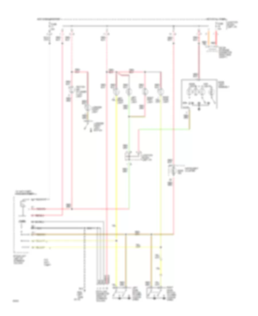
Active Aerodynamic Wiring Diagram for Mitsubishi 3000GT VR-4 1994 3000
 https://portal-diagnostov.com/license.html
Automotive Electricians Portal FZCO
Automotive Electricians Portal FZCO
https://portal-diagnostov.com/license.html
https://portal-diagnostov.com/license.html
Automotive Electricians Portal FZCO
Automotive Electricians Portal FZCO
List of elements for Active Aerodynamic Wiring Diagram for Mitsubishi 3000GT VR-4 1994 3000:
- Active aero control unit (left rear quarter panel)
- Active aero switch
- Aero ind.
- Auto1
- Auto2
- Centralized junction box (right side engine compartment)
- Data link connector (below right instrument cluster)
- Down
- F27
- F28
- Flat
- Front venturi skirt
- Fuse 10a
- Fuse 15a
- Fusible link 11 30a
- G202 (left side of i/p)
- G406 (center rear of trunk lid)
- G407 (center rear of trunk)
- Hot at all times
- Hot in run or start
- Illum.
- Ind.
- Instrument cluster
- Interior lights system
- Iod or storage connector (right eng. compt.)
- Junction block (left i/p)
- Key in
- Key out
- Key reminder switch (steering column)
- Nca
- Off
- Rear spoiler
- Red
- Slant
- Speed sensor
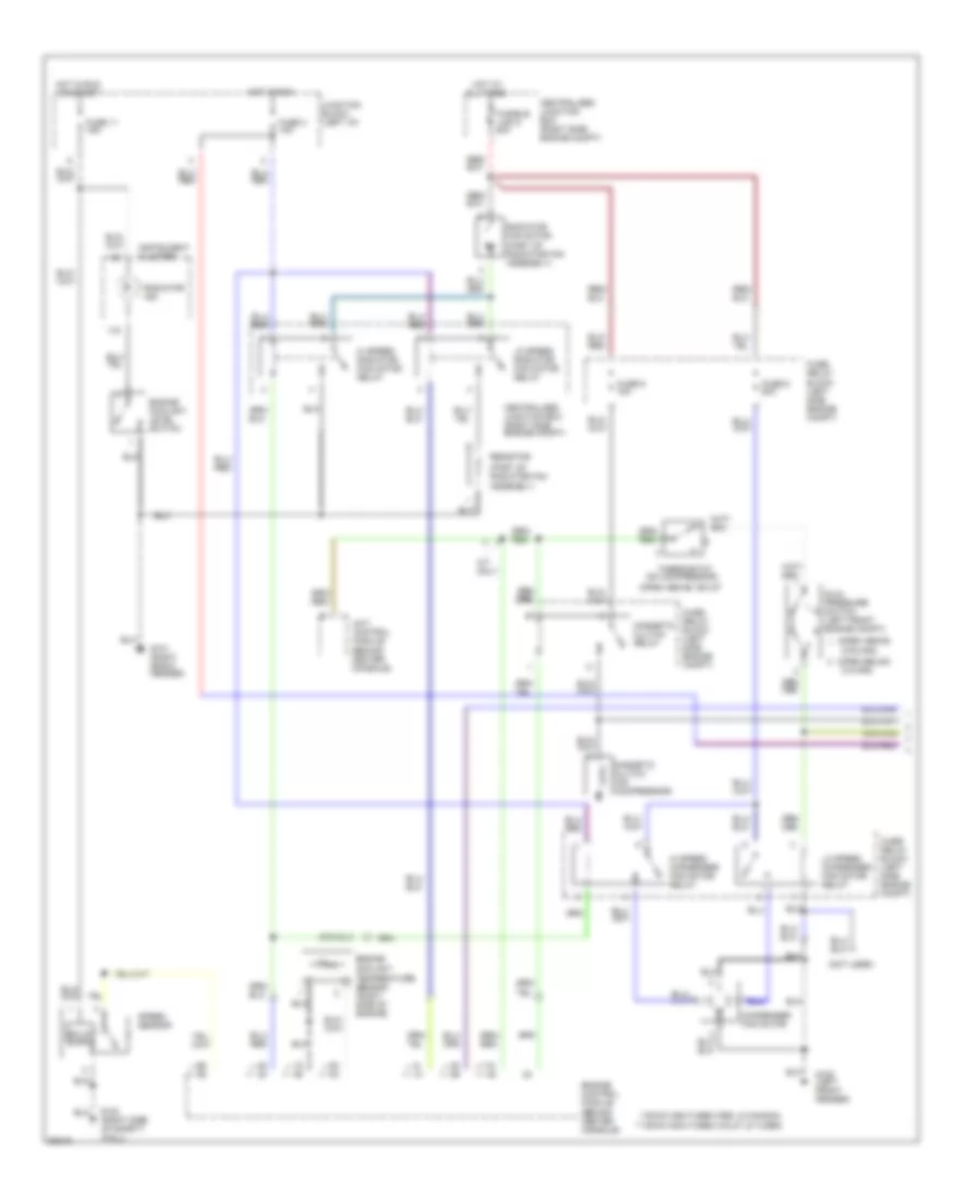
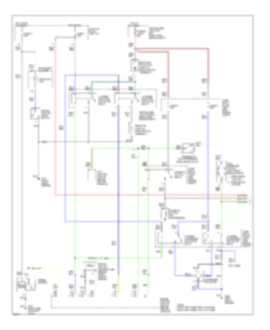
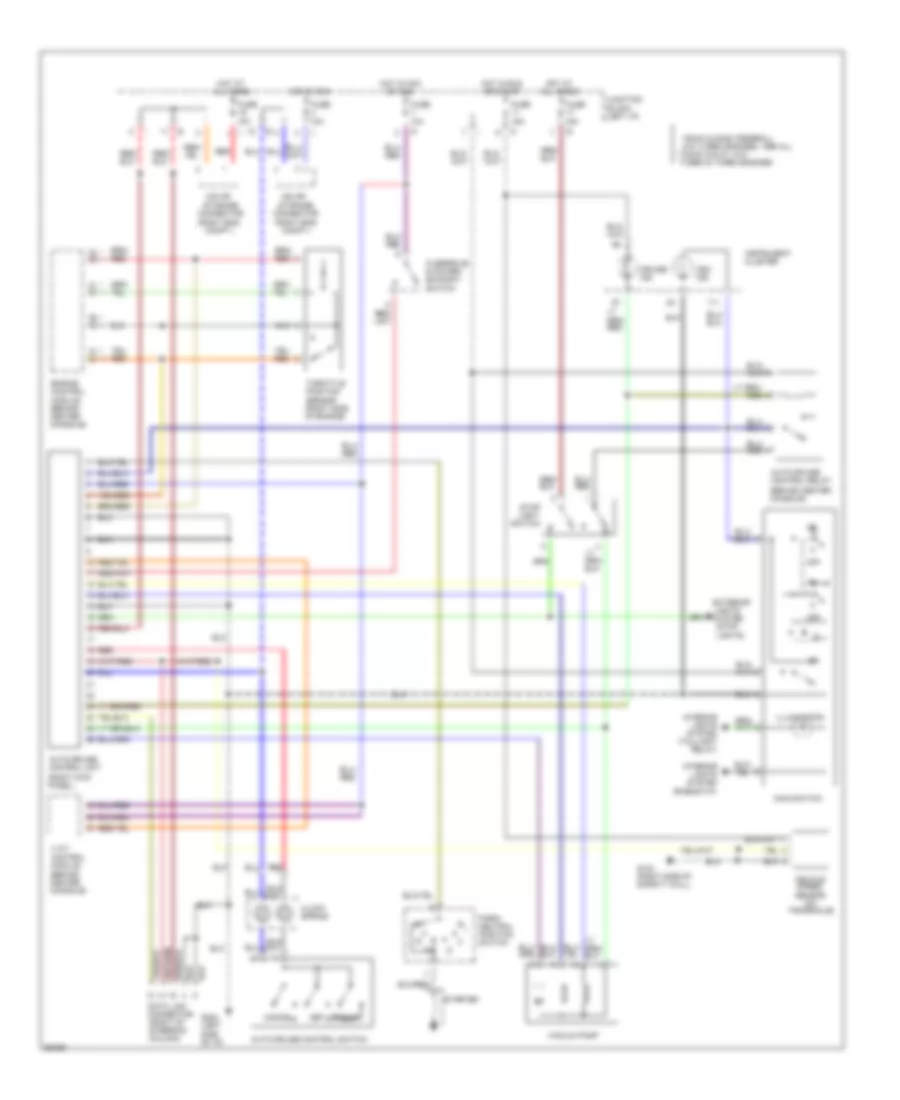
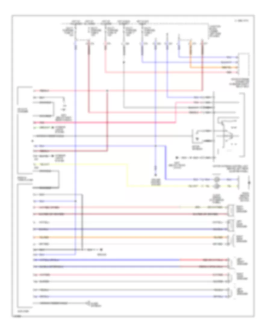
AIR CONDITIONING
A/C Wiring Diagram, Automatic (1 of 2) for Mitsubishi 3000GT VR-4 1994 3000
List of elements for A/C Wiring Diagram, Automatic (1 of 2) for Mitsubishi 3000GT VR-4 1994 3000:
- (not used)
- (on compressor)
- (open above
- (open above 155 c)
- (open below
- (part of radiator fan assembly)
- ** ***
- ***dohc non-turbo (calif.) & turbo
- **dohc non-turbo (fed. & canada)
- 210 kpa)
- 2700 kpa)
- 4a/t control module (behind center console)
- A/t only
- All times
- Centralized junction box (right side engine compt)
- Condenser fan motor
- Dual pressure switch (left front engine compt)
- Engine compt)
- Engine control module (behind center console)
- Engine coolant level switch
- Engine coolant temperature sensor (right side of engine)
- Fuse 11 15a
- Fuse 3 10a
- Fuse 8 20a
- Fuse 9 10a
- Fuse/
- Fuse/ relay block (left side engine compt)
- Fusible link 5 40a
- G100 (left front fender)
- G101 (right front fender)
- G123 (right side of safety wall)
- Hi speed condenser fan motor relay
- Hi speed radiator fan motor relay
- Hot at
- Hot in run
- Hot in run or start
- Instrument cluster
- Junction block (left i/p)
- Lo speed condenser fan motor relay
- Lo speed radiator fan motor relay
- Magnetic clutch (on compressor)
- Magnetic clutch relay
- Radiator fan motor
- Radiator ind.
- Relay block (left side
- Resistor
- Solid state
- Speed sensor
- Thermostat
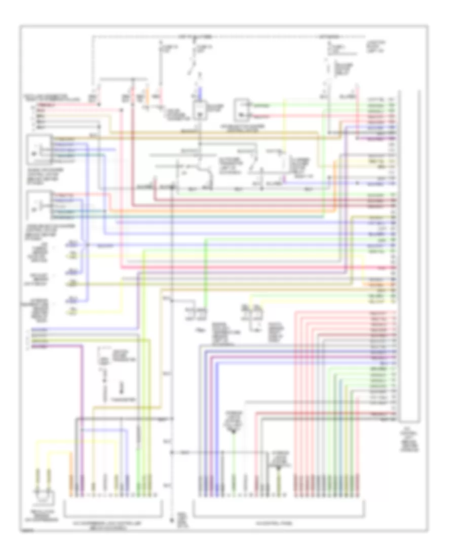
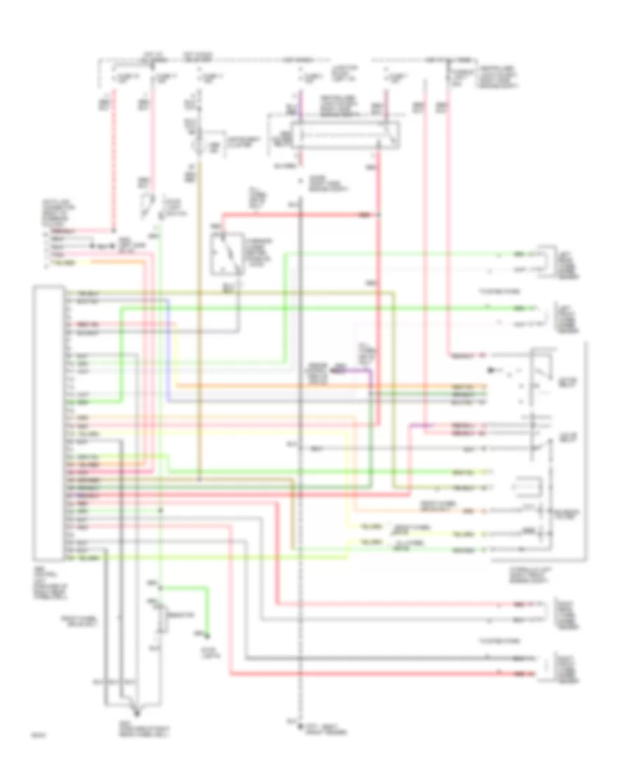
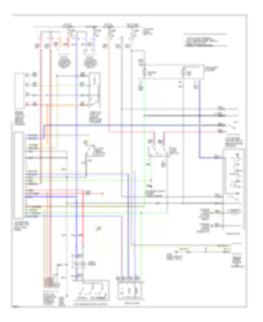
A/C Wiring Diagram, Automatic (2 of 2) for Mitsubishi 3000GT VR-4 1994 3000
List of elements for A/C Wiring Diagram, Automatic (2 of 2) for Mitsubishi 3000GT VR-4 1994 3000:
-
- hi speed blower motor relay
- (behind center
- (behind center of dash)
- (below glove box)
- (left of
- (on compressor)
- (on evap-
- (on plenum)
- (rheostat)
- (right i/p)
- (right of steering column)
- (taillight
- A/c
- A/c compressor lock controller
- A/c control panel
- A/c power transistor
- Air
- Air inlet
- Air selection damper control motor
- Blend air damper
- Blower motor
- Blower motor relay
- Console)
- Control
- Control motor
- Data link connector
- Engine coolant temperature sensor (left of glove box)
- Fuse 16 30a
- Fuse 19 10a
- Fuse 3 10a
- G202 (left side of i/p)
- Glove box)
- Hot at all times
- Hot in run
- Ignition power
- Interior
- Iod or storage connector
- Junction block (left i/p)
- Lights system
- Mode selection damper
- Nca
- Orator)
- Photo sensor (right side of dash)
- Pnk
- Red
- Relay)
- Revolution
- Roof)
- Rpm out
- Sensor
- Sensor (center rear of
- Tachometer
- Temperature
- Thermo sensor
- Transistor
- Unit
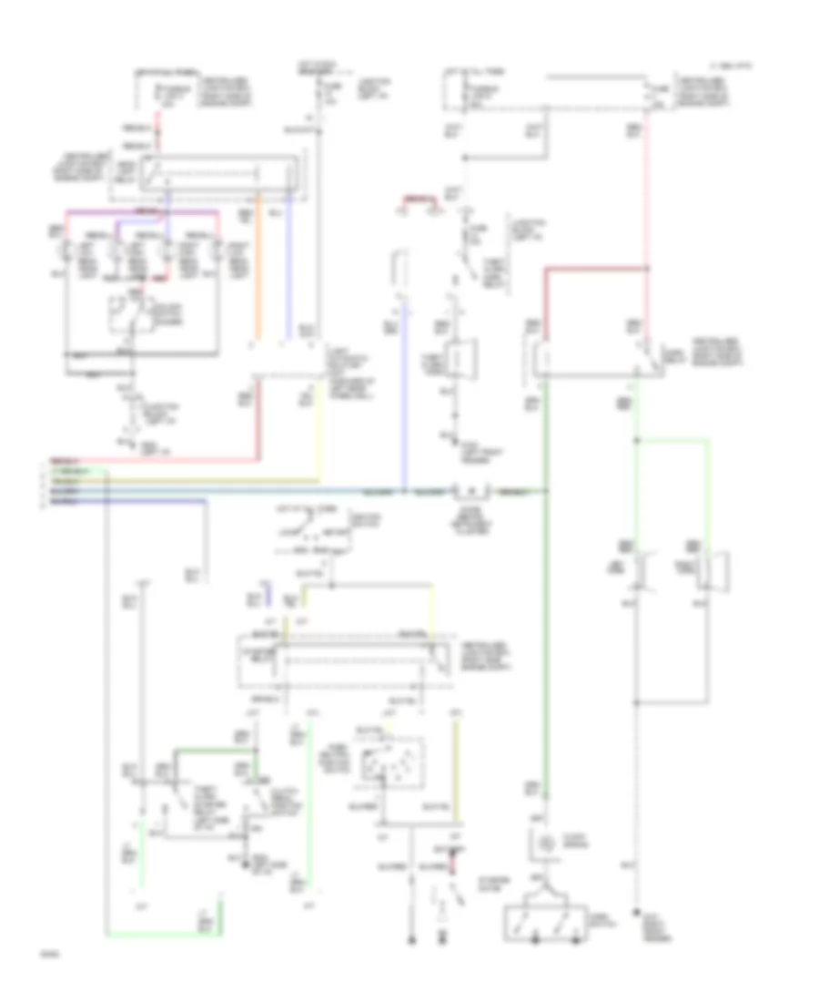
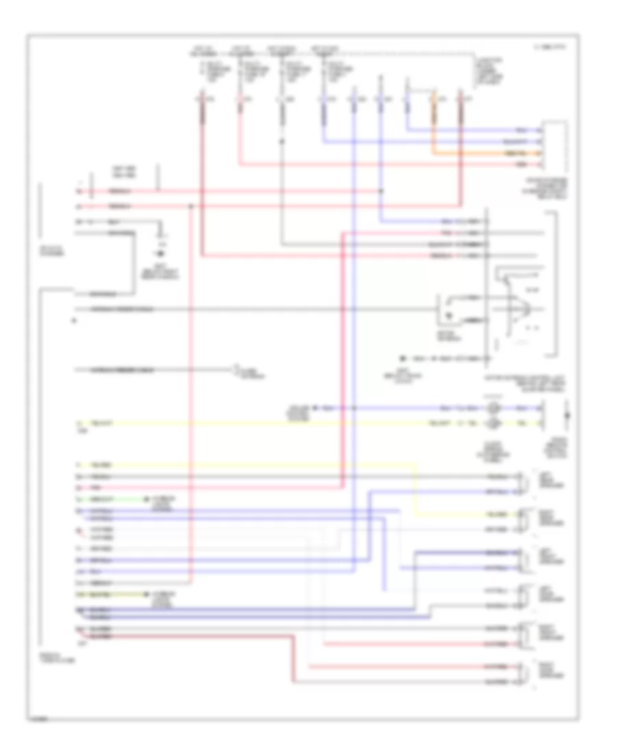
A/C Wiring Diagram, Manual (1 of 2) for Mitsubishi 3000GT VR-4 1994 3000
List of elements for A/C Wiring Diagram, Manual (1 of 2) for Mitsubishi 3000GT VR-4 1994 3000:
- (not used)
- (on compressor)
- (open above
- (open above 155 c)
- (open below
- (part of radiator fan assembly)
- * ** ***
- ***dohc non-turbo (calif.) & turbo
- **dohc non-turbo (fed. & canada)
- *sohc
- 210 kpa)
- 2700 kpa)
- 4a/t control module (behind center console)
- A/t only
- All times
- Centralized junction box (right side engine compt)
- Condenser fan motor
- Dual pressure switch (left front engine compt)
- Engine compt)
- Engine control module (behind center console)
- Engine coolant level switch
- Engine coolant temperature sensor (right side of engine)
- Fuse 11 15a
- Fuse 3 10a
- Fuse 8 20a
- Fuse 9 10a
- Fuse/
- Fuse/ relay block (left side engine compt)
- Fusible link 5 40a
- G100 (left front fender)
- G101 (right front fender)
- G123 (right side of safety wall)
- Hi speed condenser fan motor relay
- Hi speed radiator fan motor relay
- Hot at
- Hot in run
- Hot in run or start
- Instrument cluster
- Junction block (left i/p)
- Lo speed condenser fan motor relay
- Lo speed radiator fan motor relay
- Magnetic clutch (on compressor)
- Magnetic clutch relay
- Radiator fan motor
- Radiator ind.
- Relay block (left side
- Resistor
- Solid state
- Speed sensor
- Thermostat
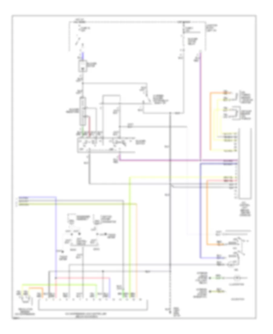
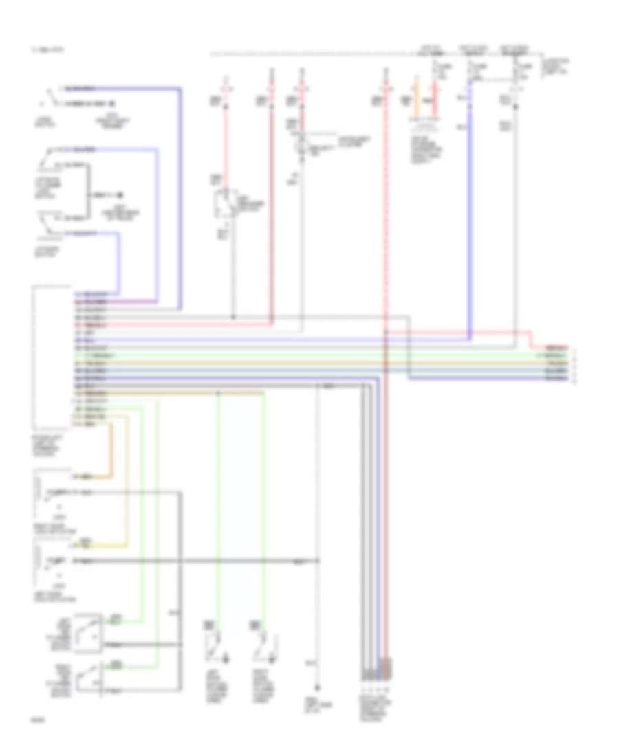
A/C Wiring Diagram, Manual (2 of 2) for Mitsubishi 3000GT VR-4 1994 3000
List of elements for A/C Wiring Diagram, Manual (2 of 2) for Mitsubishi 3000GT VR-4 1994 3000:
-
- (behind center
- (below glove box)
- (on
- (on compressor)
- (on evap-
- (right i/p)
- 4a/t
- A/c
- A/c compressor lock controller
- A/c switch
- Air
- Air inlet
- Blower motor
- Blower motor relay
- Blower resistors
- Blower switch
- Condenser assembly
- Console)
- Control
- Control module
- Dohc
- Econo
- Fuse 16 30a
- Fuse 3 10a
- G202 (left side of i/p)
- Hi speed blower motor relay
- Hot at all times
- Hot in run
- Ignition power
- Illumination
- Ind.
- Interior lights system (rheostat)
- Interior lights system (taillight relay)
- Junction block (left i/p)
- Off
- Orator)
- Plenum)
- Red
- Revolution
- Rpm out
- Sensor
- Sohc
- Tacho- meter
- Thermo sensor
- Transistor
- Unit
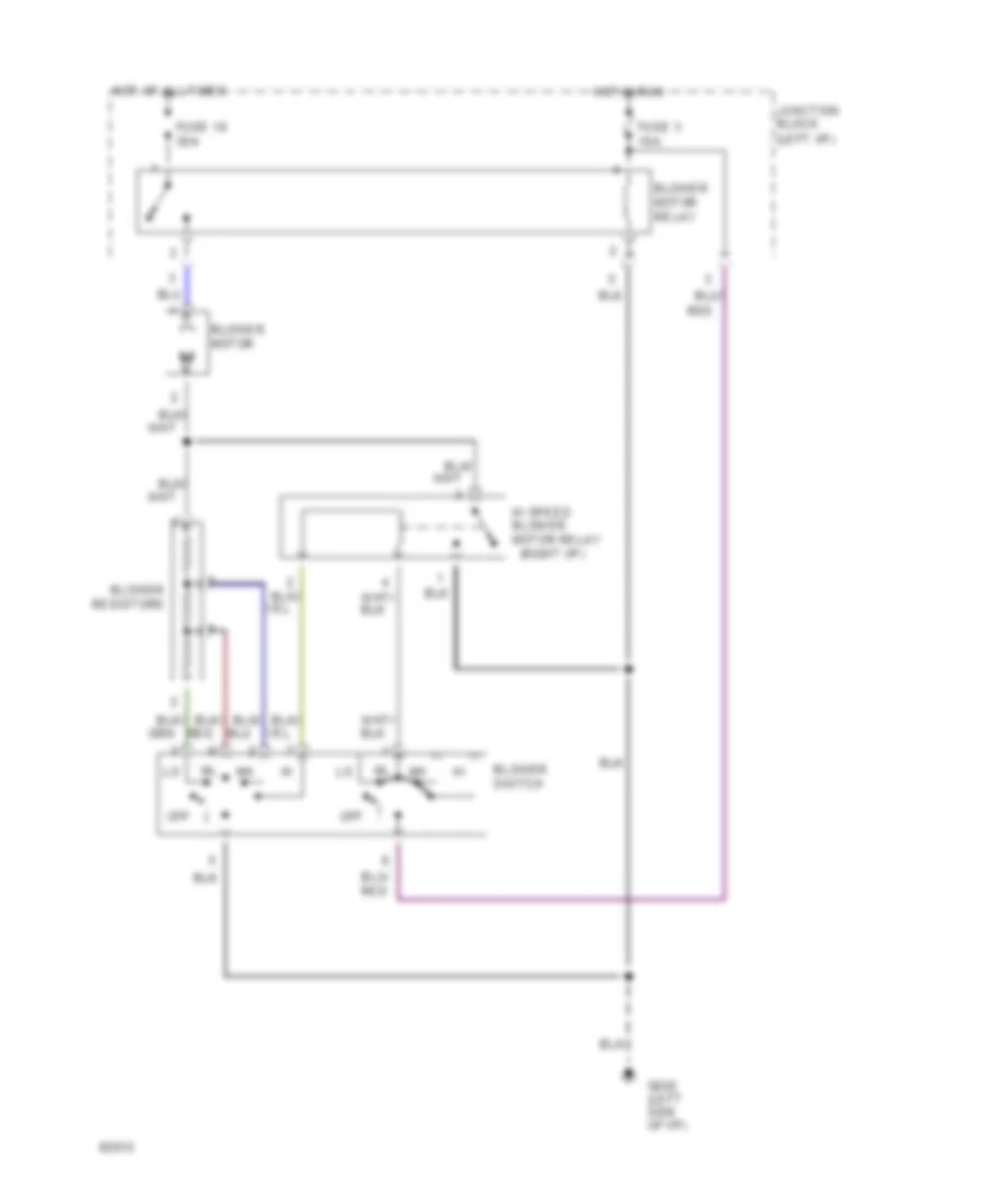
Heater Wiring Diagram for Mitsubishi 3000GT VR-4 1994 3000
List of elements for Heater Wiring Diagram for Mitsubishi 3000GT VR-4 1994 3000:
-
- (right i/p)
- Blower motor
- Blower motor relay
- Blower resistors
- Blower switch
- Fuse 16 30a
- Fuse 3 10a
- G202 (left side of i/p)
- Hi speed blower motor relay
- Hot at all times
- Hot in run
- Junction block (left i/p)
- Off
- Red
ANTI-LOCK BRAKES
Anti-lock Brake Wiring Diagrams for Mitsubishi 3000GT VR-4 1994 3000
List of elements for Anti-lock Brake Wiring Diagrams for Mitsubishi 3000GT VR-4 1994 3000:
- (awd)
- (right
- Abs
- Abs control
- Abs ind.
- All times
- All- wheel drive only
- All-wheel
- Centralized junction box (right side engine compt)
- Data link connector (right of steering column)
- Diode (right side engine compt)
- Drive
- Drive only
- Engine control module (pin 44)
- Front-wheel
- Front-wheel drive only
- Fuse 11 15a
- Fuse 17 15a
- Fuse 19 10a
- Fuse 3 10a
- Fuse 7 10a
- Fusible link 7 60a
- G sensor (under center console)
- G101 (front fender)
- G202 (left side of i/p)
- G401 (forward of right rear wheelwell)
- Hot at
- Hot at all times
- Hot in run
- Hot in run or start
- Hydraulic unit (right front engine compt)
- Instrument cluster
- Junction block (left i/p)
- Left front wheel speed sensor
- Left rear wheel speed sensor
- Motor relay
- Pnk
- Power relay
- Red
- Resistor
- Right front wheel speed sensor
- Right rear wheel speed sensor
- Solenoid valves
- Stop light switch
- Stop lights
- Twisted pairs
- Unit (forward of right rear wheelwell)
- Valve relay
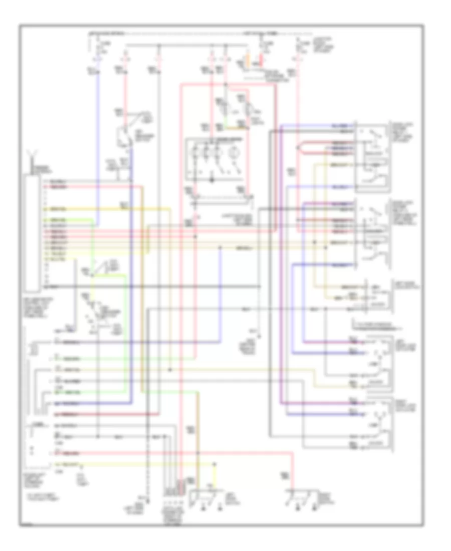
ANTI-THEFT
Anti-theft Wiring Diagram (1 of 2) for Mitsubishi 3000GT VR-4 1994 3000
List of elements for Anti-theft Wiring Diagram (1 of 2) for Mitsubishi 3000GT VR-4 1994 3000:
- (right eng. compt.)
- 1994 vftc c
- Data link connector (right of steering column)
- Door switch (closed w/door open)
- Etacs unit (left of steering column)
- Fuse 10a
- Fuse 15a
- G101 (front right fender)
- G202 (left side
- G407 (center rear of trunk)
- Hood
- Hot at all times
- Hot in acc or run
- Hot in run or start
- Instrument cluster
- Iod or storage connector
- Junction block (left i/p)
- Key reminder switch
- Left
- Left door key cylinder unlock switch
- Left door lock actuator
- Liftgate
- Liftgate cylinder
- Lock
- Of i/p)
- Red
- Right
- Right door key cylinder unlock switch
- Right door lock actuator
- Security ind.
- Switch
- Unlock
Anti-theft Wiring Diagram (2 of 2) for Mitsubishi 3000GT VR-4 1994 3000
List of elements for Anti-theft Wiring Diagram (2 of 2) for Mitsubishi 3000GT VR-4 1994 3000:
- (behind
- (right side of engine compt)
- 1994 vftc c
- A/t
- Acc
- Battery
- C64
- Centralized
- Centralized junction box (right side engine compt)
- Centralized junction box (right side of engine compt)
- Clock spring
- Cluster)
- Clutch pedal position switch
- Column switch (dimmer)
- Diode
- Fuse 10a
- Fusible link 3 40a
- Fusible link 6 40a
- G101 (right front fender)
- G10o (left front fender)
- G202 (left i/p)
- G202 (left side of i/p)
- Head- light relay
- Horn relay
- Horn switch
- Hot at all times
- Hot in run or start
- Ignition switch
- Instrument
- Junction block (left i/p)
- Junction box
- Left high beam head- light
- Left horn
- Left low beam head- light
- Light automatic shut-off unit (forward of left rear wheelwell)
- Lock
- M/t
- Neutral position
- Park/
- Red
- Relay
- Right high beam head- light
- Right horn
- Right low beam head- light
- Run
- Start
- Starter
- Starter motor
- Starter relay (left side of i/p)
- Switch
- Theft alarm horn
- Theft alarm horn relay
- Theft- alarm
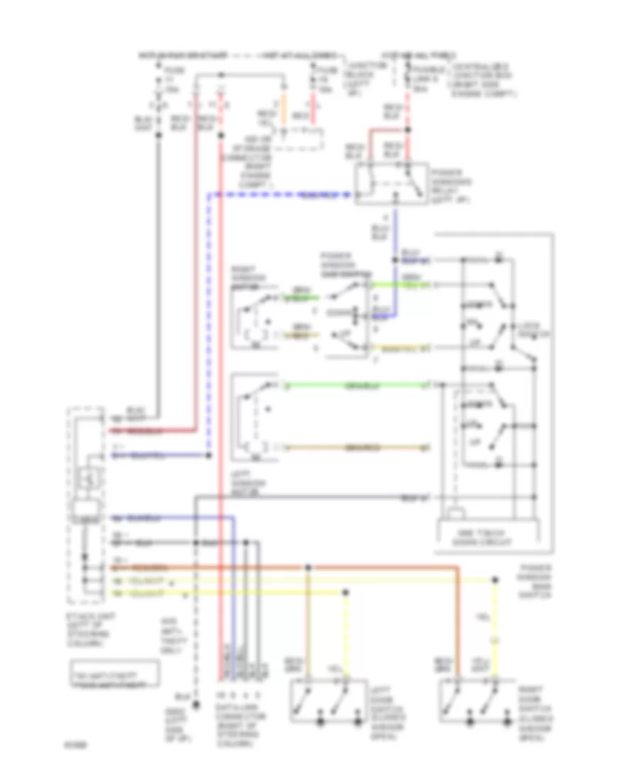
BODY COMPUTER
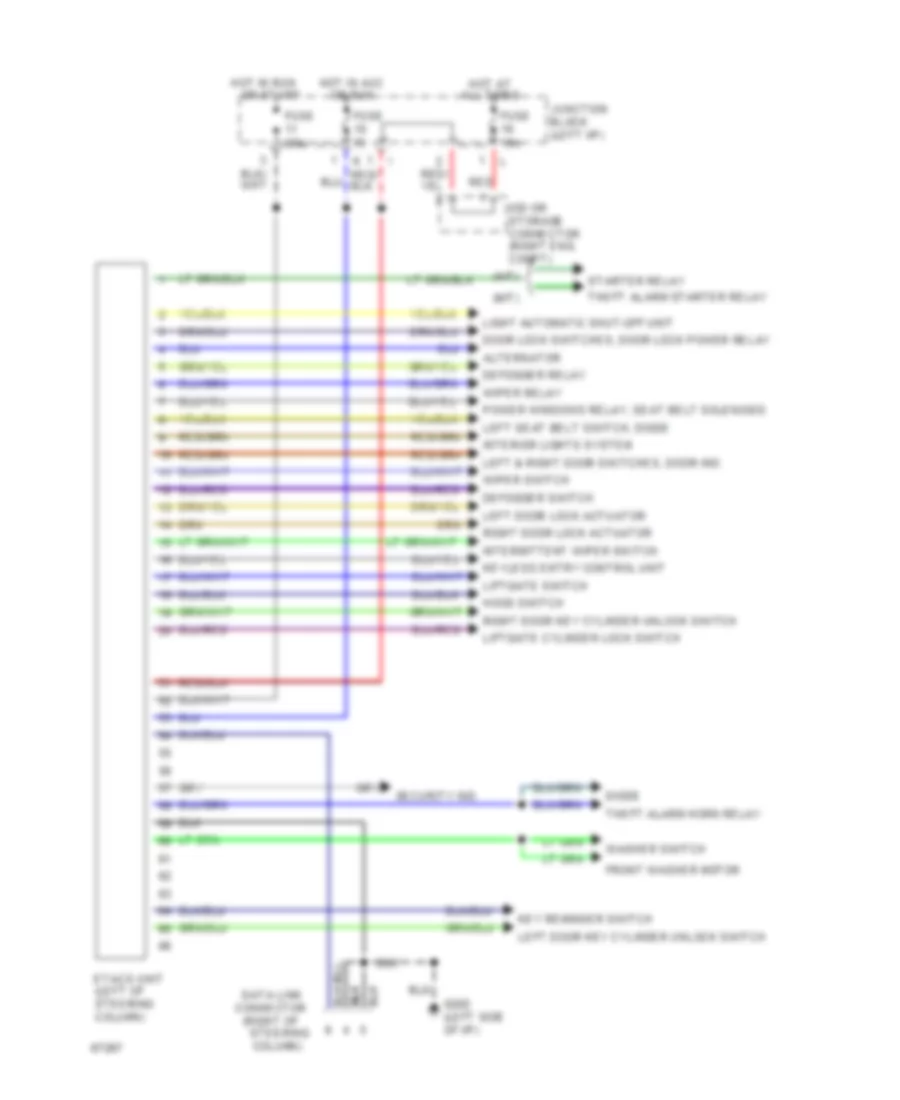
Etacs Unit Wiring Diagram, with Anti-theft for Mitsubishi 3000GT VR-4 1994 3000
List of elements for Etacs Unit Wiring Diagram, with Anti-theft for Mitsubishi 3000GT VR-4 1994 3000:
-
-
- (a/t)
- (m/t)
- (right of
- Alternator
- Connector
- Data link
- Defogger relay
- Defogger switch
- Diode
- Door lock switches, door lock power relay
- Etacs unit (left of steering column)
- Front washer motor
- Fuse
- Fuse 10a
- Fuse 15a
- G202 (left side of i/p)
- Hood switch
- Hot at all times
- Hot in acc
- Hot in run
- Interior lights system
- Intermittent wiper switch
- Iod or storage connector (right eng. compt)
- Junction block (left i/p)
- Key reminder switch
- Keyless entry control unit
- Left & right door switches, door ind.
- Left door key cylinder unlock switch
- Left door lock actuator
- Left seat belt switch, diode
- Liftgate cylinder lock switch
- Liftgate switch
- Light automatic shut-off unit
- Or run
- Or start
- Power windows relay, seat belt solenoids
- Red
- Right door key cylinder unlock switch
- Right door lock actuator
- Security ind.
- Starter relay
- Steering column)
- Theft alarm horn relay
- Theft alarm starter relay
- Washer switch
- Wiper relay
- Wiper switch
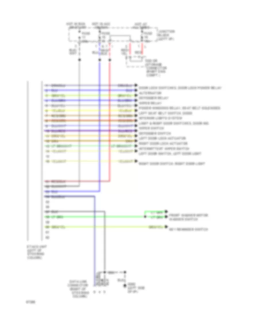
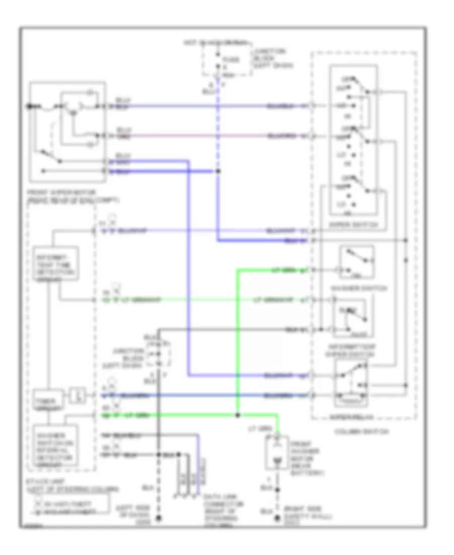
Etacs Unit Wiring Diagram, without Anti-theft for Mitsubishi 3000GT VR-4 1994 3000
List of elements for Etacs Unit Wiring Diagram, without Anti-theft for Mitsubishi 3000GT VR-4 1994 3000:
-
-
- (right of
- Alternator
- Connector
- Data link
- Defogger relay
- Defogger switch
- Door lock switches, door lock power relay
- Etacs unit (left of steering column)
- Front washer motor washer switch
- Fuse
- Fuse 10a
- Fuse 15a
- G202 (left side of i/p)
- Hot at all times
- Hot in acc
- Hot in run
- Interior lights system
- Intermittent wiper switch
- Iod or storage connector (right eng. compt.)
- Junction block (left i/p)
- Key reminder switch
- Left door lock actuator
- Left door switch, left door light
- Left seat belt switch, diode
- Light & right door switches, door ind.
- Or run
- Or start
- Power windows relay, seat belt solenoids
- Red
- Right door lock actuator
- Right door switch, right door light
- Steering column)
- Wiper relay
- Wiper switch
COMPUTER DATA LINES
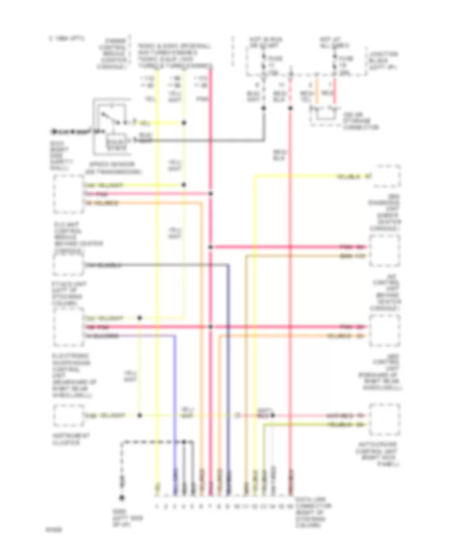
Data Link Connector Wiring Diagram for Mitsubishi 3000GT VR-4 1994 3000
List of elements for Data Link Connector Wiring Diagram for Mitsubishi 3000GT VR-4 1994 3000:
- (behind center
- (forward of
- (on transmission)
- (right kick
- (right of steering column)
- (under center
- *sohc & dohc (federal) w/o turbo engines **dohc (calif.) w/o turbo & turbo engines
- 1994 vftc c
- A/c
- Abs
- Auto-cruise
- Console)
- Control
- Control unit
- Data link connector
- Diagnosis
- Elc-4a/t control module (behind center
- Electronic suspension control unit (rearward of right rear wheelwell)
- Engine
- Etacs unit (left of steering column)
- Fuse 10a
- Fuse 15a
- G123 (right side safety wall)
- G202 (left side of i/p)
- Hot at all times
- Hot in run or start
- Instrument cluster
- Iod or storage connector
- Junction block (left i/p)
- Module (center
- Panel)
- Pnk
- Red
- Right rear wheelwell)
- Solid state
- Speed sensor
- Srs
- Unit
COOLING FAN
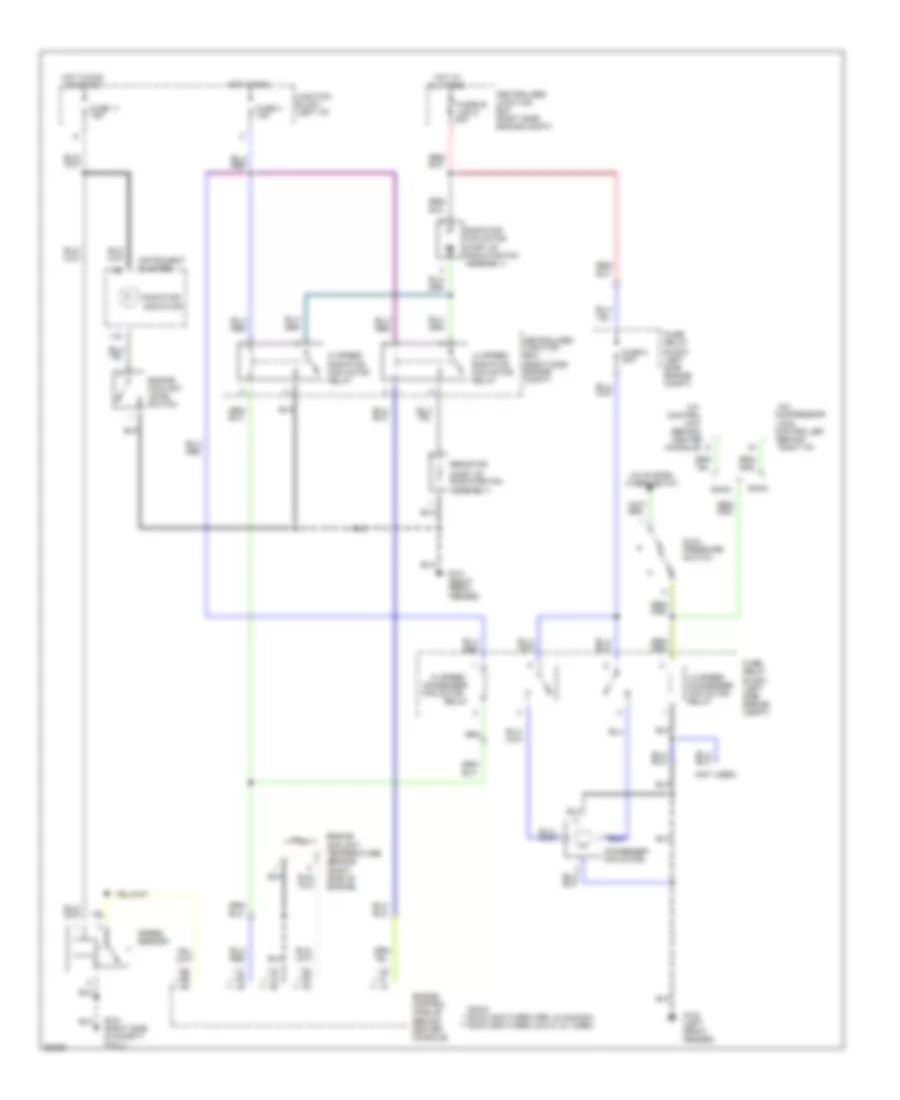
Cooling Fan Wiring Diagram for Mitsubishi 3000GT VR-4 1994 3000
List of elements for Cooling Fan Wiring Diagram for Mitsubishi 3000GT VR-4 1994 3000:
- (behind
- (behind center
- (not used)
- (part of radiator fan assembly)
- * ** ***
- ***dohc non-turbo (calif.) & turbo
- **dohc non-turbo (fed. & canada)
- *sohc
- A/c
- A/c system (thermostat)
- All times
- Centralized junction box (right side engine compt)
- Compressor
- Condenser fan motor
- Console)
- Control
- Controller
- Dohc
- Dual pressure switch
- Engine control module (behind center console)
- Engine coolant level switch
- Engine coolant temperature sensor (right side of engine)
- Fuse 11 15a
- Fuse 3 10a
- Fuse 8 20a
- Fuse/ relay block (left side engine compt)
- Fusible link 5 40a
- G100 (left front fender)
- G101 (right front fender)
- G123 (right side of safety wall)
- Hi speed
- Hi speed radiator fan motor relay
- Hot at
- Hot in run
- Hot in run or start
- Instrument cluster
- Junction block (left i/p)
- Lo speed condenser fan motor relay
- Lo speed radiator fan motor relay
- Lock
- Radiator fan motor
- Radiator indicator
- Relay
- Resistor
- Right i/p)
- Sohc
- Speed sensor
- Unit
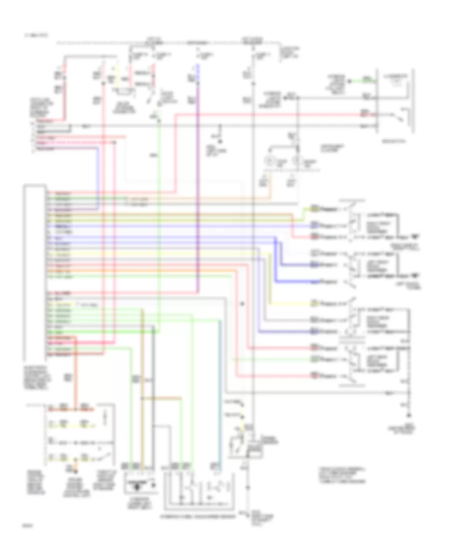
CRUISE CONTROL
Cruise Control Wiring Diagram, A/T for Mitsubishi 3000GT VR-4 1994 3000
List of elements for Cruise Control Wiring Diagram, A/T for Mitsubishi 3000GT VR-4 1994 3000:
- (behind center console)
- (on
- (right eng. compt.)
- (right kick panel)
- (stop
- * **
- *sohc & dohc (federal) w/o turbo engines, 1996 all **dohc (calif.) w/o turbo & turbo engines
- 4 a/t control module (behind center console)
- Asc ind.
- Auto-cruise control relay
- Auto-cruise control switch
- Auto-cruise control unit
- Cancel
- Clock spring
- Connector
- Cruise ind.
- Data link connector (right of steering column)
- Engine control module (behind center console)
- Exterior
- Fuse 10a
- Fuse 15a
- G123 (right side of safety wall)
- G202 (left side of i/p)
- Hot at all times
- Hot in acc
- Hot in run
- Hot in run or start
- Illumination
- Instrument cluster
- Interior lights system (rheostat)
- Interior lights system (taillight relay)
- Iod or storage
- Junction block (left i/p)
- Lights system
- Lights)
- Main switch
- Off
- Or run
- Overdrive & power/ economy switch
- Park/ neutral position switch
- Red
- Resume
- Set
- Starter
- Stop light
- Switch
- Throttle position sensor (right side of engine)
- Transaxle)
- Vacuum pump
- Vehicle speed sensor
Cruise Control Wiring Diagram, M/T for Mitsubishi 3000GT VR-4 1994 3000
List of elements for Cruise Control Wiring Diagram, M/T for Mitsubishi 3000GT VR-4 1994 3000:
- (behind center console)
- (on
- (right eng. compt.)
- (right kick panel)
- (stop lights)
- * **
- *sohc & dohc (federal) w/o turbo engines, 1996 all **dohc (calif.) w/o turbo & turbo engines
- Asc ind.
- Auto-cruise control relay
- Auto-cruise control switch
- Auto-cruise control unit
- C63
- Cancel
- Clock spring
- Clutch pedal position switch
- Connector
- Cruise ind.
- Data link connector (right of steering column)
- Engine control module (behind center console)
- Exterior lights
- Fuse 10a
- Fuse 15a
- G123 (right side of safety wall)
- G202 (left side of i/p)
- Hot at all times
- Hot in run
- Hot in run or start
- Illumination
- Instrument cluster
- Interior lights system (rheostat)
- Interior lights system (taillight relay)
- Iod or storage
- Junction block (left i/p)
- Main switch
- Off
- Red
- Resume
- Set
- Stop light switch
- System
- Throttle position sensor (right side of engine)
- Transaxle)
- Vacuum pump
- Vehicle speed sensor
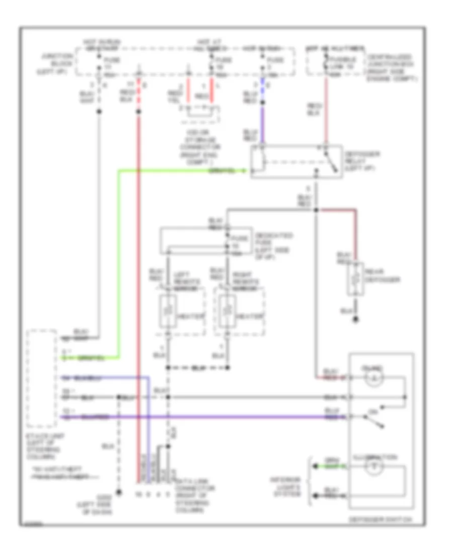
DEFOGGERS
Defogger Wiring Diagram for Mitsubishi 3000GT VR-4 1994 3000
List of elements for Defogger Wiring Diagram for Mitsubishi 3000GT VR-4 1994 3000:
- (left i/p)
- (right eng. compt.)
- * **
- *w/ anti-theft **w/o anti-theft
- Block
- Centralized junction box (right side engine compt)
- Connector
- Data link connector (right of steering column)
- Dedicated fuse (left side of i/p)
- Defogger
- Defogger relay (left i/p)
- Defogger switch
- Etacs unit (left of steering column)
- Fuse 10a
- Fuse 15a
- Fusible link 10 40a
- G202 (left side of dash)
- Heater
- Hot at all times
- Hot in run
- Hot in run or start
- Illumination
- Interior lights system
- Iod or storage
- Junction
- Left remote mirror
- On ind.
- Rear
- Red
- Right remote mirror
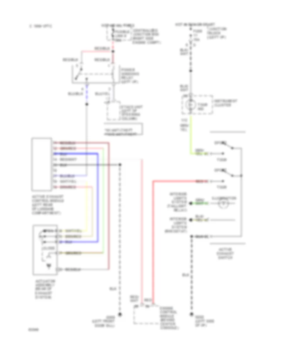
ELECTRONIC MUFFLER
Active Exhaust Wiring Diagram for Mitsubishi 3000GT VR-4 1994 3000
List of elements for Active Exhaust Wiring Diagram for Mitsubishi 3000GT VR-4 1994 3000:
- (left front
- * **
- *w/ anti-theft **w/o anti-theft
- 1994 vftc c
- Active exhaust control module (left rear of luggage compartment)
- Active exhaust switch
- Actuator assembly (rear of exhaust system)
- Centralized junction box (right side engine compt)
- Close
- Door sill)
- Engine control module (behind center console)
- Etacs unit (left of steering column)
- Fuse 15a
- Fusible link 9 30a
- G202 (left side of i/p)
- G309
- Hot at all times
- Hot in run or start
- Illumination
- Instrument cluster
- Interior lights system (rheostat)
- Interior lights system (taillight relay)
- Junction block (left i/p)
- Open
- Power windows relay (left i/p)
- Red
- Sport
- Tour
- Tour ind.
ELECTRONIC SUSPENSION
Electronic Suspension Wiring Diagram for Mitsubishi 3000GT VR-4 1994 3000
List of elements for Electronic Suspension Wiring Diagram for Mitsubishi 3000GT VR-4 1994 3000:
- (auto-cruise control unit)
- (center rear
- (left shock
- (right side of
- (right side of engine)
- (under left front seat)
- * **
- **sohc & dohc (federal) w/o turbo engines *dohc (calif.) w/o turbo & turbo engines
- 1994 vftc c
- All times
- Amplifier
- Connector
- Control system
- Cruise
- Data link connector (right of steering column)
- Ecs switch
- Electronic suspension control unit (rearward of right rear wheelwell)
- Engine control module (behind center console)
- Fuse 11 15a
- Fuse 17 15a
- Fuse 19 10a
- Fuse 3 10a
- G sensor
- G102
- G123
- G123 (right side of safety wall)
- G202 (left side of i/p)
- G407
- Hot at
- Hot in run
- Hot in run or start
- Illumination
- Instrument cluster
- Interior lights system (rheostat)
- Interior lights system (taillight relay)
- Iod or storage
- Junction block (left i/p)
- Left front shock absorber
- Left rear shock absorber
- Nca
- Of trunk)
- Pnk
- Red
- Right front shock absorber
- Right rear shock absorber
- Safety wall)
- Solid state
- Speed sensor
- Sport ind.
- Steering wheel angle speed sensor
- Stop light switch
- Throttle position sensor
- Tour ind.
- Tower)
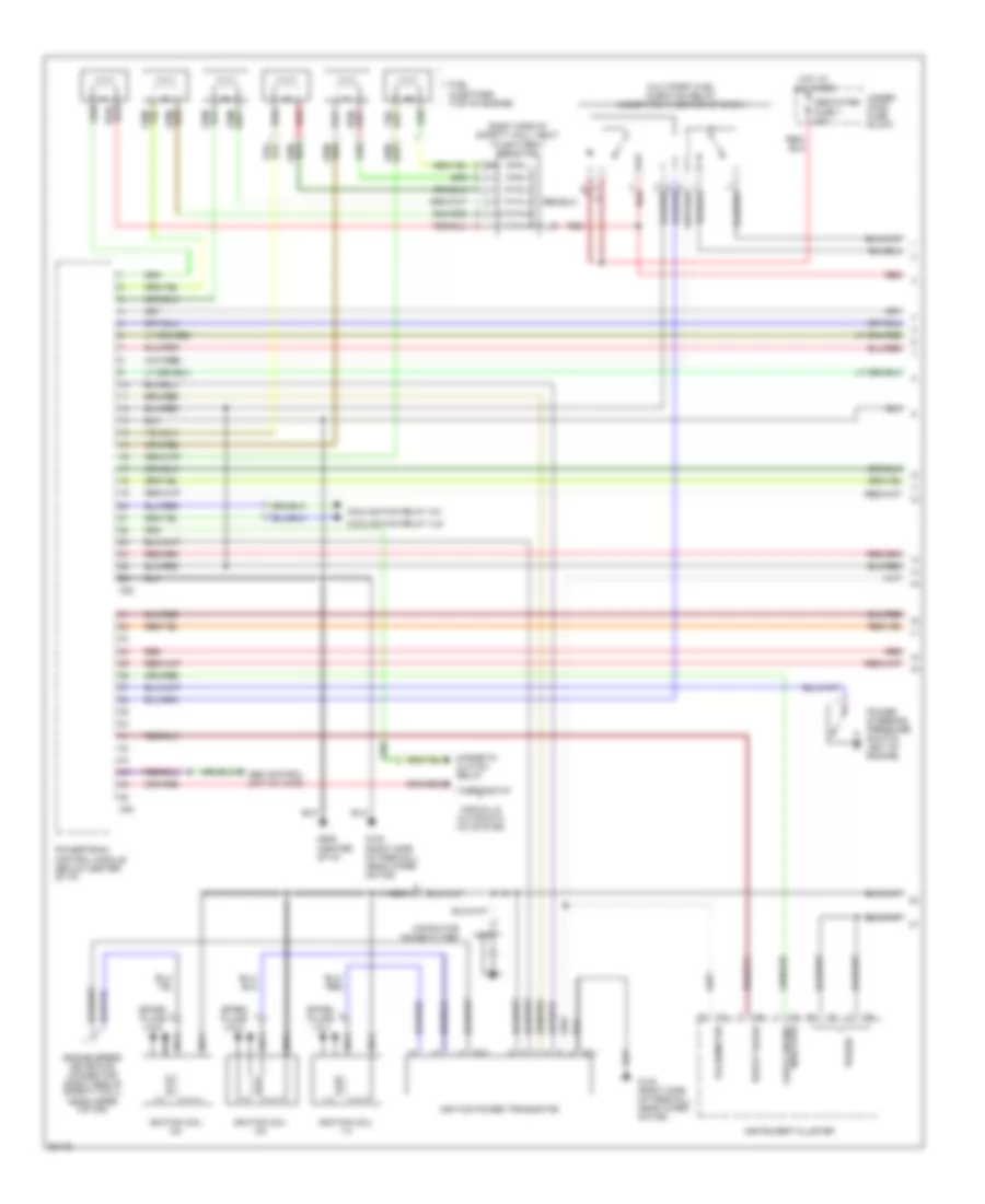
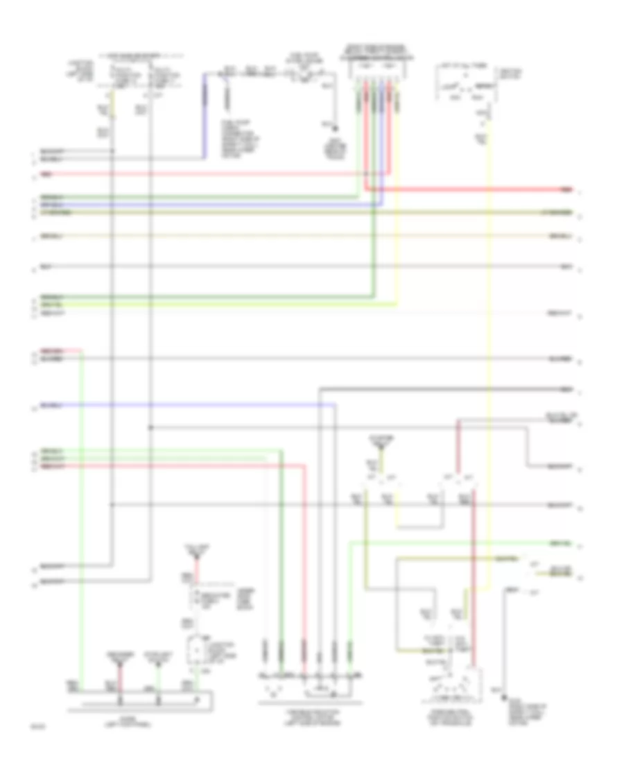
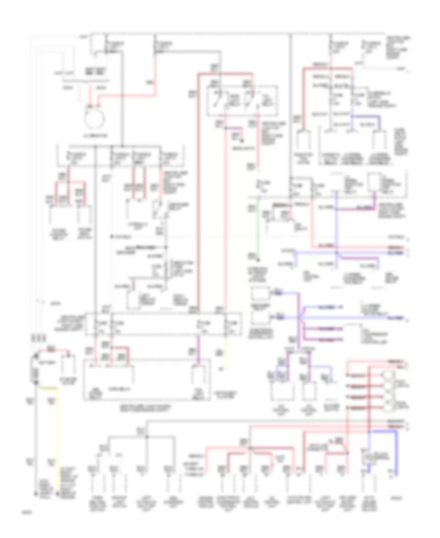
ENGINE PERFORMANCE
3.0L
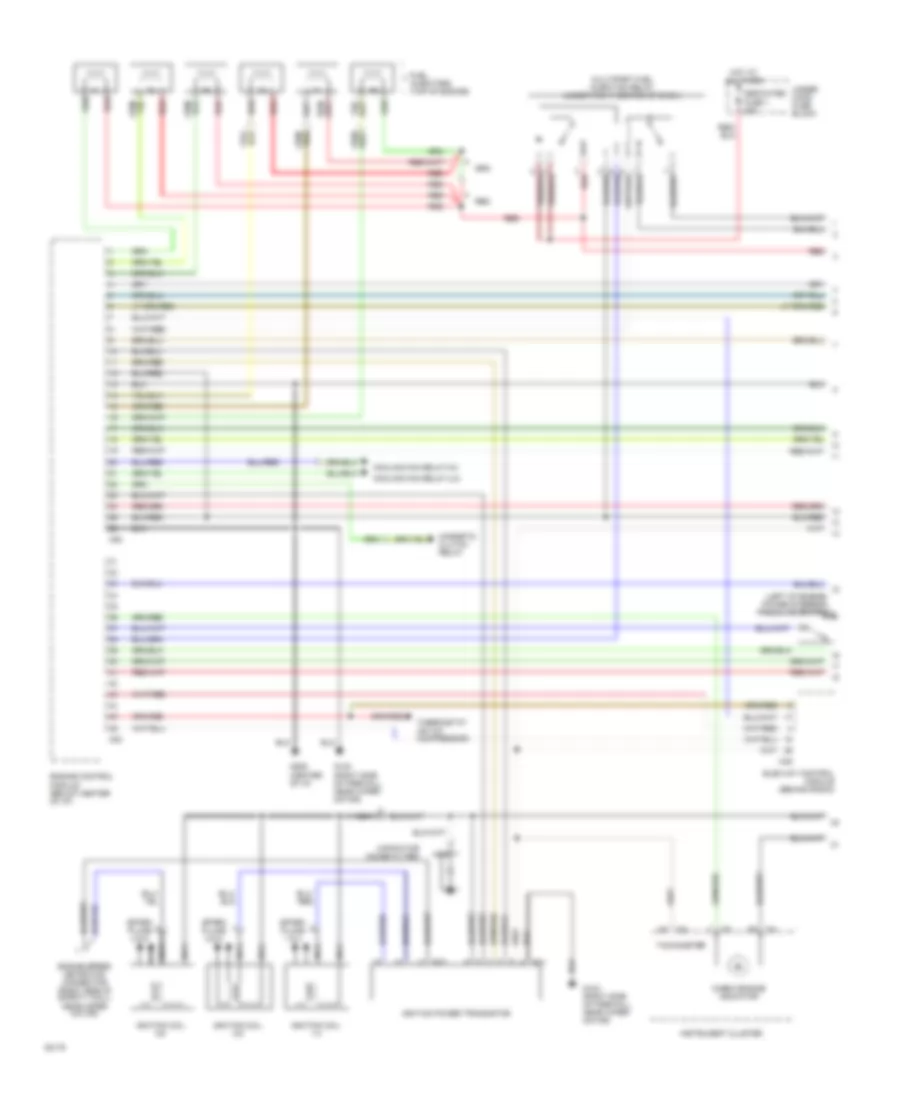
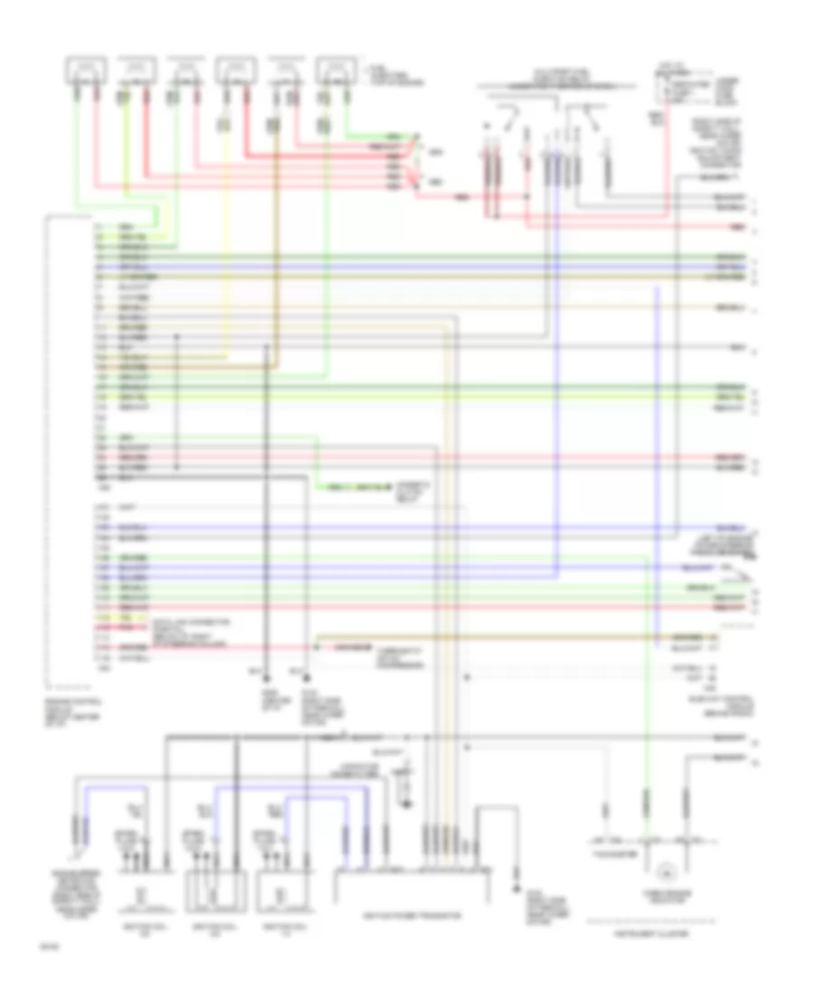
3.0L DOHC Turbo, Engine Performance Wiring Diagrams (1 of 3) for Mitsubishi 3000GT VR-4 1994 3000
List of elements for 3.0L DOHC Turbo, Engine Performance Wiring Diagrams (1 of 3) for Mitsubishi 3000GT VR-4 1994 3000:
- (right side of safety wall, next to battery) resistor
- Abs control unit (w/ awd)
- B21
- B22
- Boost gauge
- C52
- C53
- Capacitor (noise filter)
- Check engine indicator
- Cooling fan relay (hi)
- Cooling fan relay (lo)
- Dedicated fuse 1 20a
- Engine speed detection connector (right side of safety wall) near wiper motor)
- Fuel injectors (top of engine)
- G123 (right side of firewall, near wiper motor)
- G206 (center of i/p,
- Hot at all times
- Ignition coil 1-4
- Ignition coil 2-5
- Ignition coil 3-6
- Ignition power transistor
- Instrument cluster
- Magnetic clutch relay
- Manual & automatic a/c system
- Multiport fuel injection relay (under right center of dash)
- Nca
- Power
- Power steering pressure switch left of engine)
- Powertrain control module (below center of i/p)
- Red
- Spark plugs 1 & 4
- Spark plugs 2 & 5
- Spark plugs 3 & 6
- Tachometer
- Thermostat
- Under- hood fuse block
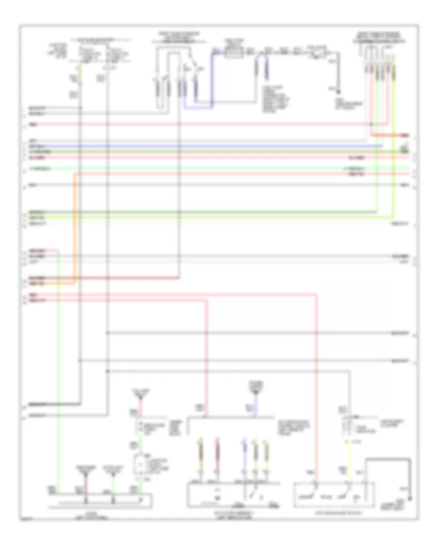
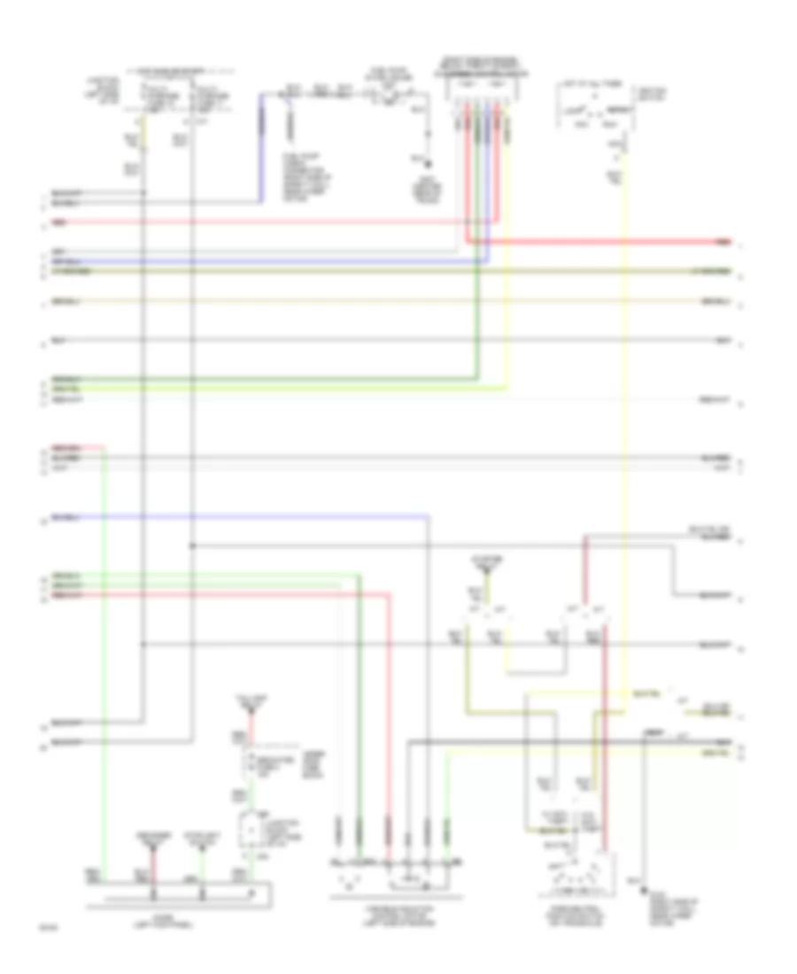
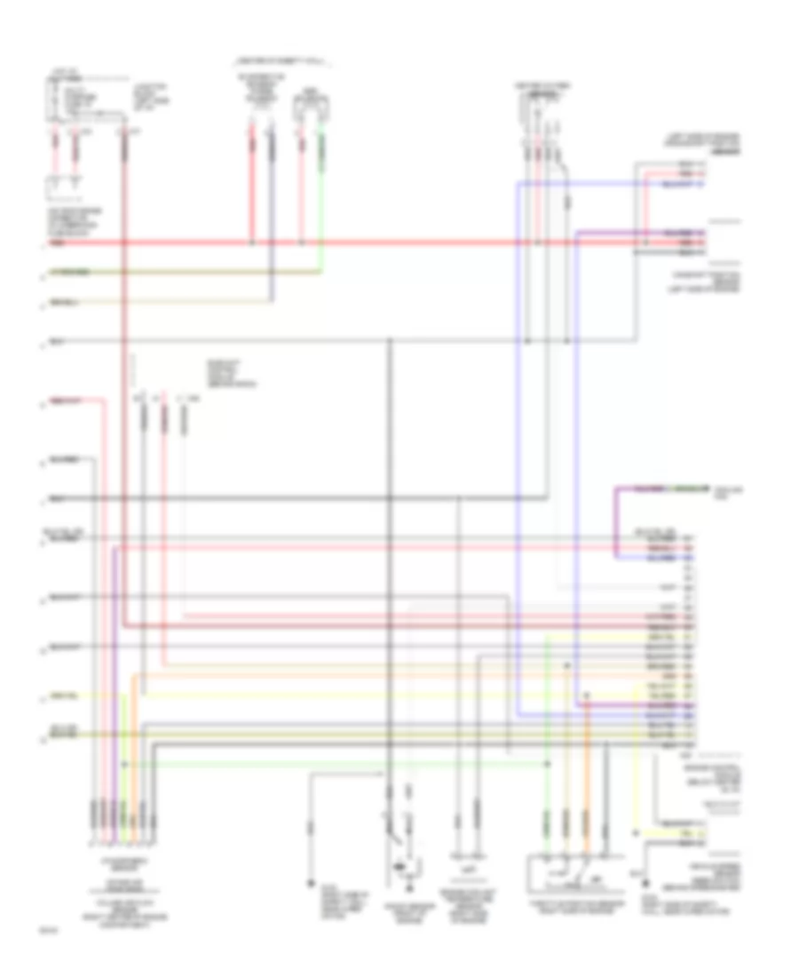
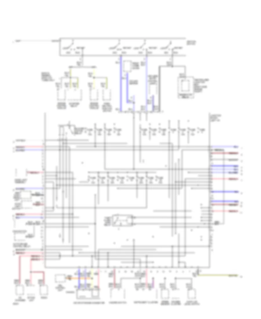
3.0L DOHC Turbo, Engine Performance Wiring Diagrams (2 of 3) for Mitsubishi 3000GT VR-4 1994 3000
List of elements for 3.0L DOHC Turbo, Engine Performance Wiring Diagrams (2 of 3) for Mitsubishi 3000GT VR-4 1994 3000:
- (right side of engine compartment) fuel pump relay
- (right side of engine, below throttle body) idle speed control motor
- Active exhaust control module (left rear of trunk)
- Active exhaust switch
- Actuator assembly (left rear of car)
- C112
- C59
- C69
- C71
- C83
- Dedicated fuse 2 15a
- Defogger relay
- Diode (left kick panel)
- Fuel pump
- Fuel pump check connector (right side of safety wall, near wiper motor)
- Fuel pump circuit resistor
- Full close
- Full open
- G300 (under left front seat)
- G407 (center rear of trunk)
- Hot in on or start
- Instrument cluster
- Junction block (left side of i/p)
- Multi- function fuse 11 15a
- Multi- function fuse 12 15a
- Nca
- Off
- Power mirror relay
- Red
- Sport
- Stoplight switch
- Taillight relay
- Tour
- Tour indicator
- Under- hood fuse block
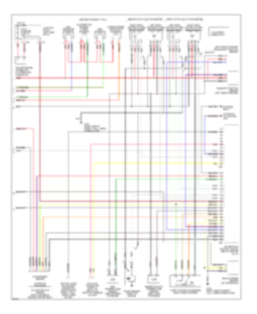
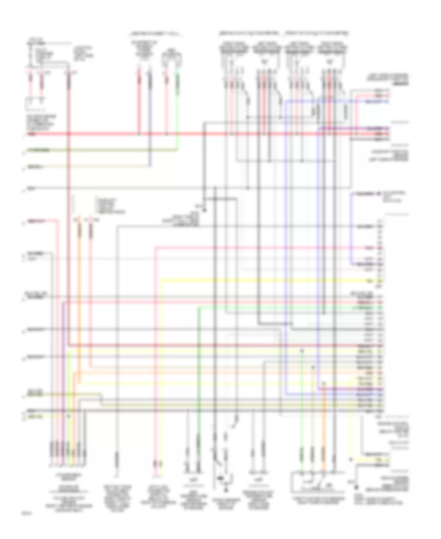
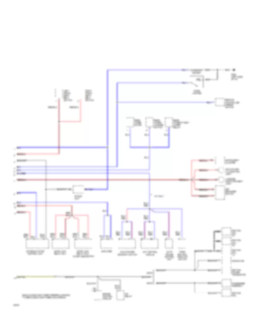
3.0L DOHC Turbo, Engine Performance Wiring Diagrams (3 of 3) for Mitsubishi 3000GT VR-4 1994 3000
List of elements for 3.0L DOHC Turbo, Engine Performance Wiring Diagrams (3 of 3) for Mitsubishi 3000GT VR-4 1994 3000:
- (behind catalytic converter)
- (center of safety wall)
- (front of catalytic converter)
- (left side of engine) crankshaft position sensor
- * california models only
- Atmospheric sensor
- Automatic a/c control unit
- C54
- C90
- Camshaft position sensor (left side of engine)
- Data link connector (partial) (below i/p, right of steering column)
- Egr solenoid
- Egr temperature sensor (center rear of engine)
- Engine coolant temperature sensor (right side of engine)
- Evaporative emission purge solenoid
- Fuel pressure solenoid
- G123 (right side of safety wall, near wiper motor)
- Hot at all times
- Ignition timing adjustment connector (right side of safety wall, near wiper motor)
- Intake air temp sens
- Iod or storage connector (in underhood fuse block)
- Junction block (left side of i/p)
- Knock sensor (front of engine)
- Left bank heated oxygen sensor (front)
- Left bank heated oxygen sensor (rear)
- Multi- purpose fuse 19 10a
- Nca
- Off
- Pnk
- Powertrain control module (below center of i/p)
- Red
- Right bank heated oxygen sensor (front)
- Right bank heated oxygen sensor (rear)
- Starter relay
- Throttle position sensor (right side of engine)
- Turbocharger waste gate solenoid
- Vehicle speed sensor (on transaxle)
- Volume air flow sensor (right center of engine compartment)
3.0L DOHC, Engine Performance Wiring Diagrams, California (1 of 3) for Mitsubishi 3000GT VR-4 1994 3000
List of elements for 3.0L DOHC, Engine Performance Wiring Diagrams, California (1 of 3) for Mitsubishi 3000GT VR-4 1994 3000:
- (left of engine) power steering pressure switch
- B21
- B22
- C46
- C52
- C53
- Capacitor (noise filter)
- Check engine indicator
- Cooling fan relay (hi)
- Cooling fan relay (lo)
- Dedicated fuse 1 20a
- Elec-4at control module (behind radio)
- Engine control module (below center of i/p)
- Engine speed detection connector (right side of safety wall) near wiper motor)
- Fuel injectors (top of engine)
- G123 (right side of firewall, near wiper motor)
- G206 (center of i/p,
- Hot at all times
- Ignition coil 1-4
- Ignition coil 2-5
- Ignition coil 3-6
- Ignition power transistor
- Instrument cluster
- Magnetic clutch relay
- Multiport fuel injection relay (under right center of dash)
- Nca
- Red
- Spark plugs 1 & 4
- Spark plugs 2 & 5
- Spark plugs 3 & 6
- Tachometer
- Thermostat (on a/c compressor)
- Under- hood fuse block
3.0L DOHC, Engine Performance Wiring Diagrams, California (2 of 3) for Mitsubishi 3000GT VR-4 1994 3000
List of elements for 3.0L DOHC, Engine Performance Wiring Diagrams, California (2 of 3) for Mitsubishi 3000GT VR-4 1994 3000:
- (right side of engine, below throttle body) idle speed control motor
- A/t
- Acc
- B10
- C69
- C71
- C83
- Dedicated fuse 2 15a
- Defogger relay
- Diode (left kick panel)
- Fuel pump & fuel gauge unit
- Fuel pump check connector (right side of safety wall, near wiper motor)
- G123 (right side of safety wall, near wiper motor)
- G407 (center rear of trunk)
- Hot at all times
- Hot in on or start
- Ignition switch
- Junction block (left side of i/p)
- Lock
- M/t
- Multi- purpose fuse 11 15a
- Multi- purpose fuse 12 15a
- Nca
- Park/neutral position switch (on transaxle)
- Red
- Run
- Start
- Starter relay
- Stoplight switch
- Taillight relay
- Under- hood fuse block
- Variable induction control motor (left side of engine)
- W/ anti- theft
- W/o anti- theft
3.0L DOHC, Engine Performance Wiring Diagrams, California (3 of 3) for Mitsubishi 3000GT VR-4 1994 3000
List of elements for 3.0L DOHC, Engine Performance Wiring Diagrams, California (3 of 3) for Mitsubishi 3000GT VR-4 1994 3000:
- (behind catalytic converter)
- (center of safety wall)
- (front of catalytic converter)
- (left side of engine) crankshaft position sensor
- A/c control unit (auto a/c)
- Atmospheric sensor
- C46
- C54
- C90
- Camshaft position sensor (left side of engine)
- Data link connector (partial) (below i/p, right of steering column)
- Egr solenoid
- Egr temperature sensor (center rear of engine)
- Elec-4a/t control module (behind radio)
- Engine control module (below center of i/p)
- Engine coolant temperature sensor (right side of engine)
- Evaporative emission purge solenoid
- G123 (right side of safety wall, near wiper motor)
- Hot at all times
- Ignition timing adjustment connector (right side of safety wall, near wiper motor)
- Intake air temp sens
- Iod or storage connector (in underhood fuse block)
- Junction block (left side of i/p)
- Knock sensor (front of engine)
- Left bank heated oxygen sensor (front)
- Left bank heated oxygen sensor (rear)
- Multi- purpose fuse 19 10a
- Nca
- Off
- Pnk
- Red
- Right bank heated oxygen sensor (front)
- Right bank heated oxygen sensor (rear)
- Throttle position sensor (right side of engine)
- Vehicle speed sensor (reed switch) (behind speedometer)
- Volume air flow sensor (right center of engine compartment)
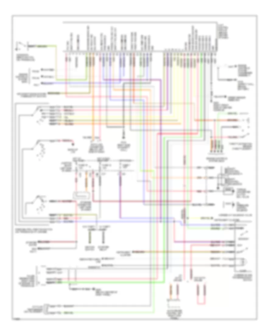
3.0L DOHC, Engine Performance Wiring Diagrams, Federal (1 of 3) for Mitsubishi 3000GT VR-4 1994 3000
List of elements for 3.0L DOHC, Engine Performance Wiring Diagrams, Federal (1 of 3) for Mitsubishi 3000GT VR-4 1994 3000:
- (left of engine) power steering pressure switch
- (right side of safety wall, near wiper motor) ignition timing adjustment connector
- B21
- B22
- C46
- C52
- C54
- Capacitor (noise filter)
- Check engine indicator
- Data link connector (partial) (below i/p, right of steering column)
- Dedicated fuse 1 20a
- Elec-4at control module (behind radio)
- Engine control module (below center of i/p)
- Engine speed detection connector (right side of safety wall) near wiper motor)
- Fuel injectors (top of engine)
- G123 (right side of firewall, near wiper motor)
- G206 (center of i/p,
- Hot at all times
- Ignition coil 1-4
- Ignition coil 2-5
- Ignition coil 3-6
- Ignition power transistor
- Instrument cluster
- Magnetic clutch relay
- Multiport fuel injection relay (under right center of dash)
- Nca
- Pnk
- Red
- Spark plugs 1 & 4
- Spark plugs 2 & 5
- Spark plugs 3 & 6
- Tachometer
- Thermostat (on a/c compressor)
- Under- hood fuse block
3.0L DOHC, Engine Performance Wiring Diagrams, Federal (2 of 3) for Mitsubishi 3000GT VR-4 1994 3000
List of elements for 3.0L DOHC, Engine Performance Wiring Diagrams, Federal (2 of 3) for Mitsubishi 3000GT VR-4 1994 3000:
- (right side of engine, below throttle body) idle speed control motor
- A/t
- Acc
- B10
- C69
- C71
- C83
- Dedicated fuse 2 15a
- Defogger relay
- Diode (left kick panel)
- Fuel pump & fuel gauge unit
- Fuel pump check connector (right side of safety wall, near wiper motor)
- G123 (right side of safety wall, near wiper motor)
- G407 (center rear of trunk)
- Hot at all times
- Hot in on or start
- Ignition switch
- Junction block (left side of i/p)
- Lock
- M/t
- Multi- function fuse 11 15a
- Multi- function fuse 12 15a
- Nca
- Park/neutral position switch (on transaxle)
- Red
- Run
- Start
- Starter relay
- Stoplight switch
- Taillight relay
- Under- hood fuse block
- Variable induction control motor (left side of engine)
- W/ anti- theft
- W/o anti- theft
3.0L DOHC, Engine Performance Wiring Diagrams, Federal (3 of 3) for Mitsubishi 3000GT VR-4 1994 3000
List of elements for 3.0L DOHC, Engine Performance Wiring Diagrams, Federal (3 of 3) for Mitsubishi 3000GT VR-4 1994 3000:
- (center of safety wall)
- (left side of engine) crankshaft position sensor
- Atmospheric sensor
- C46
- C53
- Camshaft position sensor (left side of engine)
- Cooling fan
- Egr solenoid
- Elec-4a/t control module (behind radio)
- Engine control module (below center of i/p)
- Engine coolant temperature sensor (right side of engine)
- Evaporative emission purge solenoid
- G123 (right side of safety wall, near wiper motor)
- Heated oxygen sensor
- Hot at all times
- Intake air temp sens
- Iod or storage connector (in underhood fuse block)
- Junction block (left side of i/p)
- Knock sensor (front of engine)
- Multi- purpose fuse 19 10a
- Nca
- Off
- Red
- Throttle position sensor (right side of engine)
- Vehicle speed sensor (reed switch) (behind speedometer)
- Volume air flow sensor (right center of engine compartment)
EXTERIOR LIGHTS
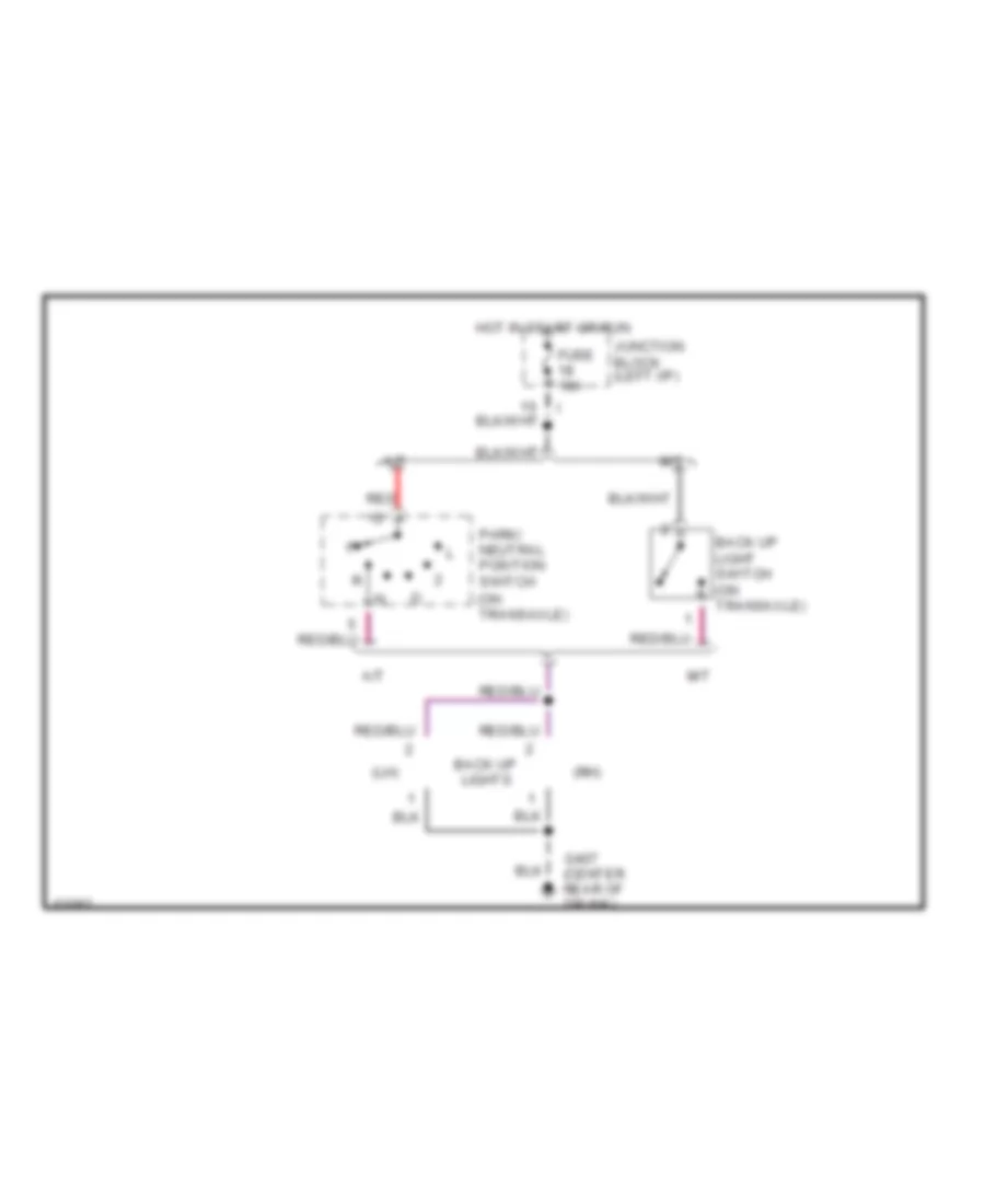
Back-up Lamps Wiring Diagram for Mitsubishi 3000GT VR-4 1994 3000
List of elements for Back-up Lamps Wiring Diagram for Mitsubishi 3000GT VR-4 1994 3000:
- (lh)
- (on transaxle)
- (rh)
- A/t
- Back up light switch (on transaxle)
- Back up lights
- Fuse 10a
- G407 (center rear of trunk)
- Hot in start or run
- Junction block (left i/p)
- M/t
- Park/ neutral position switch
- Red
Park, Stop, Tail & Turn Lamps Wiring Diagram, Large Bumper for Mitsubishi 3000GT VR-4 1994 3000
List of elements for Park, Stop, Tail & Turn Lamps Wiring Diagram, Large Bumper for Mitsubishi 3000GT VR-4 1994 3000:
-
-
-
-
- tail
- (center rear of trunk)
- e
- (right side of engine compt)
- All times
- Centralized
- Column switch (light switch)
- Column switch (turn- signal
- Door switch
- Fuse 10a
- Fuse 15a
- Fuse 15a
- Fuse 2 15a
- Fuse 6 10a
- Fusible link 3 40a
- G100 (left front fender)
- G101 (right front fender)
- G202 (left side
- G406 (center rear of trunk lid)
- G407
- G407 (center rear of trunk)
- Hazard
- Hazard switch
- Head
- High mounted stop lights
- Hot at
- Hot at all times
- Hot in run or start
- Hot in run or start
- Instrument cluster
- Iod or storage connector (right eng. compt.)
- Junction block (left i/p)
- Junction box
- Left
- Left
- Left front park/ turn light
- Left rear tail/ stop/ turn lights
- License plate lights
- Light automatic shut-off unit (forward of left rear wheelwell)
- Nca
- Of i/p)
- Off
- Red
- Rheostat
- Right front park/ turn light
- Right rear tail/ stop/ turn lights
- Right turn ind.
- Solid state
- Stop light switch
- Switch)
- Tail
- Tail- light relay
- Turn ind.
- Turn signal/ hazard flasher unit (left kick panel)
Park, Stop, Tail & Turn Lamps Wiring Diagram, Small Bumper-Type 1 for Mitsubishi 3000GT VR-4 1994 3000
List of elements for Park, Stop, Tail & Turn Lamps Wiring Diagram, Small Bumper-Type 1 for Mitsubishi 3000GT VR-4 1994 3000:
-
-
-
-
- hazard switch
- tail
- head
- light automatic shut-off unit (forward of left rear wheelwell)
- (center rear of trunk)
- (right side of engine compt)
- All times
- Centralized
- Column switch (light switch)
- Column switch (turn- signal
- Fender)
- Fuse 15a
- Fuse 10a
- Fuse 15a
- Fuse 2 15a
- Fuse 6 10a
- Fusible link 3 40a
- G100 (left front
- G101 (right front fender)
- G202 (left side
- G202 (left side of i/p)
- G406 (center rear of trunk lid)
- G407
- G407 (center rear of trunk)
- Hazard
- Head
- High mounted stop lights
- Hot at
- Hot at all times
- Hot in run or start
- Instrument cluster
- Iod or storage connector (right eng. compt.)
- Junction block (left i/p)
- Junction box
- Left door switch
- Left front park/ turn light
- Left rear tail/ stop/ turn lights
- Left turn ind.
- License plate lights
- Nca
- Of i/p)
- Off
- Red
- Rheostat
- Right front park/ turn light
- Right rear tail/ stop/ turn lights
- Right turn ind.
- Solid state
- Stop light switch
- Switch)
- Tail
- Tail- light relay
- Turn signal & hazard flasher unit (left kick panel)
Park, Stop, Tail & Turn Lamps Wiring Diagram, Small Bumper-Type 2 for Mitsubishi 3000GT VR-4 1994 3000
List of elements for Park, Stop, Tail & Turn Lamps Wiring Diagram, Small Bumper-Type 2 for Mitsubishi 3000GT VR-4 1994 3000:
-
-
-
-
- rheostat
- tail
- (center rear of trunk)
- off
- (right side of engine compt)
- All times
- Centralized
- Column switch (light switch)
- Column switch (turn- signal
- Fender)
- Fuse 15a
- Fuse 10a
- Fuse 15a
- Fuse 2 15a
- Fuse 6 10a
- Fusible link 3 40a
- G100 (left front
- G101 (right front fender)
- G202 (left side
- G202 (left side of i/p)
- G406 (center rear of trunk lid)
- G407
- G407 (center rear of trunk)
- Hazard
- Hazard switch
- Head
- High mounted stop lights
- Hot at
- Hot at all times
- Hot in run or start
- Hot in run or start
- Instrument cluster
- Iod or storage connector (right eng. compt.)
- Junction block (left i/p)
- Junction box
- Left door switch
- Left front park/ turn light
- Left rear tail/ stop/ turn lights
- Left turn ind.
- License plate lights
- Light automatic shut-off unit (forward of left rear wheelwell)
- Nca
- Of i/p)
- Off
- Red
- Right front park/ turn light
- Right rear tail/ stop/ turn lights
- Right turn ind.
- Solid state
- Stop light switch
- Switch)
- Tail
- Tail- light relay
- Turn signal & hazard flasher unit (left kick panel)
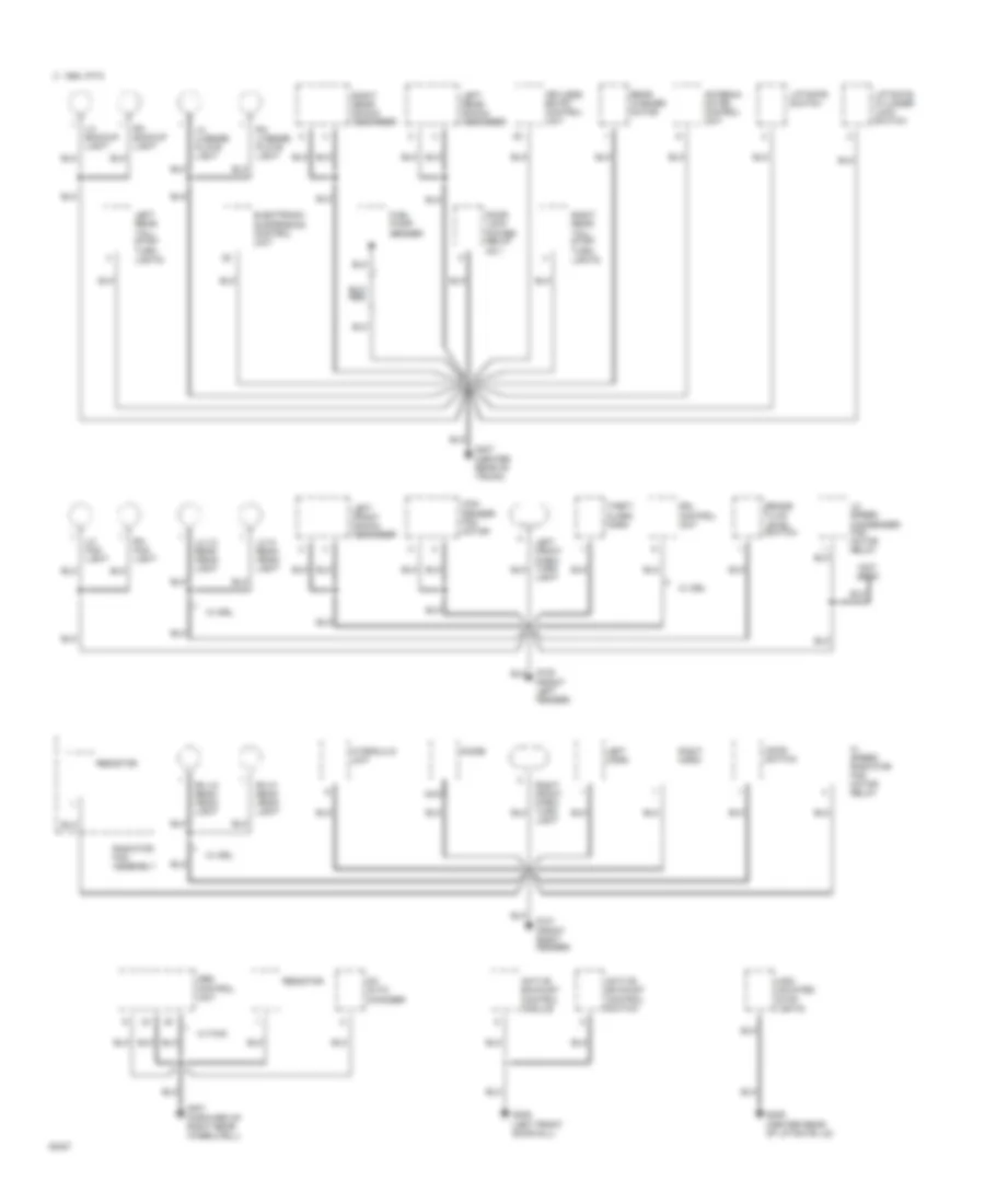
GROUND DISTRIBUTION
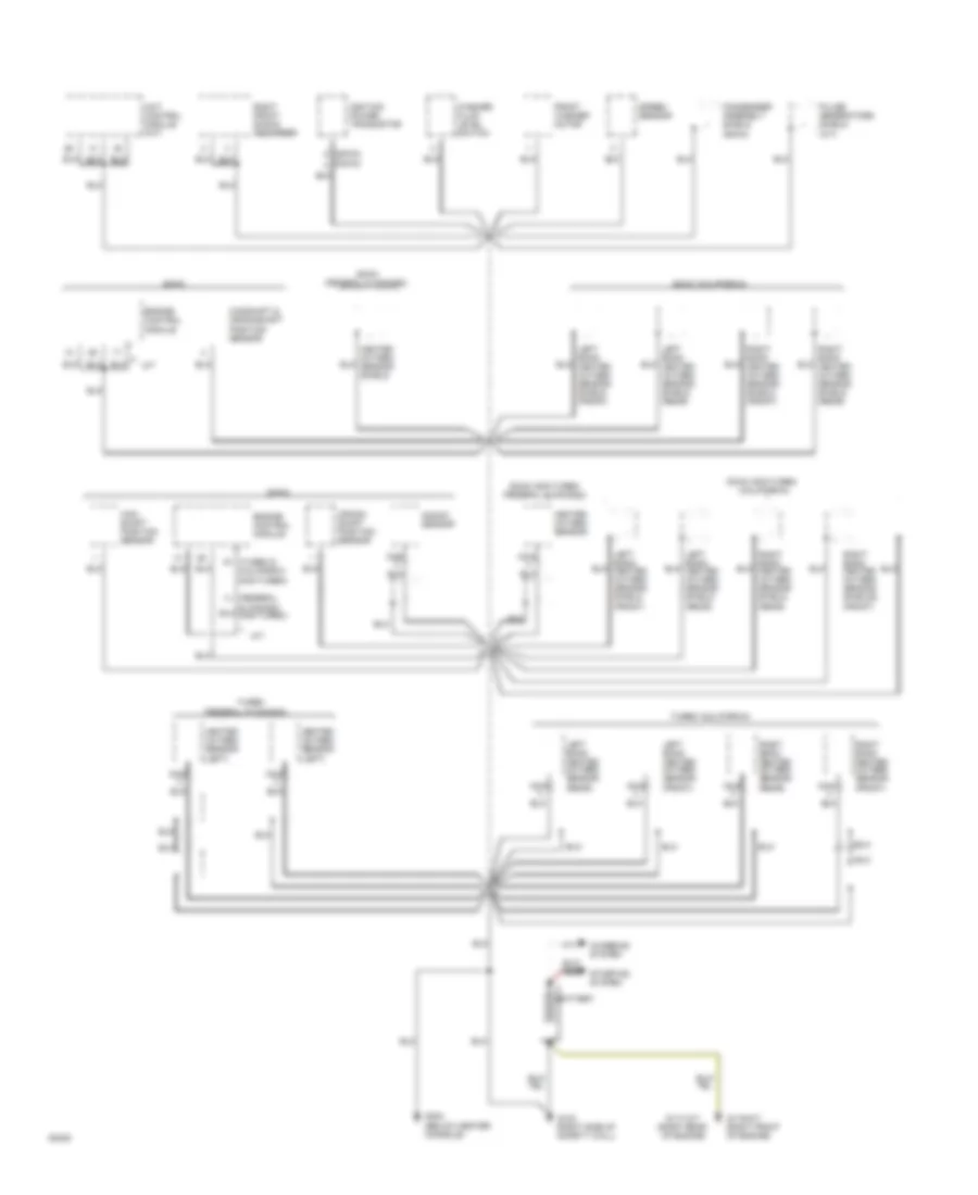
Ground Distribution Wiring Diagram (1 of 3) for Mitsubishi 3000GT VR-4 1994 3000
List of elements for Ground Distribution Wiring Diagram (1 of 3) for Mitsubishi 3000GT VR-4 1994 3000:
- (a/t)
- (below center console)
- (california)
- (dohc)
- (federal & canada non-turbo)
- (federal & canada)
- (left)
- (right rear
- (sohc)
- (turbo & california non-turbo)
- 4a/t control module (a/t)
- Battery
- Cam- shaft position sensor
- Camshaft & crankshaft position sensor
- Charging system
- Condenser assembly shield
- Crank- shaft position sensor
- Dohc
- Dohc non-turbo
- Engine control module
- Front washer motor
- G117-a/t
- G119-m/t (right front of engine)
- G123 (right side of safety wall)
- G302
- Heated oxygen sensor
- Heated oxygen sensor shield
- Ignition power transistor
- Knock sensor
- Left bank heated oxygen sensor (front)
- Left bank heated oxygen sensor (rear)
- Left bank heated oxygen sensor shield (front)
- Left bank heated oxygen sensor shield (rear)
- M/t
- Nca
- Of engine)
- Pulse generators shield
- Right bank heated oxygen sensor (front)
- Right bank heated oxygen sensor (rear)
- Right bank heated oxygen sensor shield (front)
- Right bank heated oxygen sensor shield (rear)
- Right bank heated oxygen sensor shields (front)
- Right front shock absorber
- Sohc
- Sohc (california)
- Speed sensor
- Starting system
- Turbo
- Turbo (california)
- Washer fluid level switch
Ground Distribution Wiring Diagram (2 of 3) for Mitsubishi 3000GT VR-4 1994 3000
List of elements for Ground Distribution Wiring Diagram (2 of 3) for Mitsubishi 3000GT VR-4 1994 3000:
- (auto) (man.)
- (left side of i/p)
- (small bumper- type 1)
- (small bumper- type 2 & large bumper)
- (w/ anti- theft)
- (w/ power windows)
- (w/o anti- theft)
- (w/o power windows)
- A/c compressor lock controller
- A/c control panel
- A/c control unit
- Accessory
- Auto
- Auto- cruise control unit
- Blower motor relay
- Blower switch
- Cigar lighter
- Clutch pedal position switch (m/t)
- Column switch
- Data link connector
- Defogger switch
- Dimmer/ passing switch
- Door lock power relay no.2 (w/ keyless entry)
- Ecs switch
- Engine coolant temperature sensor
- Etacs unit
- G202
- Gauges cluster
- Hi speed blower motor relay
- Instrument cluster
- Junction block
- Key reminder switch (w/o anti- theft)
- Left door key cylinder unlock switch
- Left door lock actuator
- Left door lock switch
- Left remote mirror
- Lh lo beam head- light
- Light switch
- Main switch
- Manual
- Nca
- Power seat assembly
- Power seat switch
- Power window main switch
- Red
- Remote controlled mirror switch
- Rh lo beam head- light
- Rheostat
- Right door key cylinder unlock switch
- Right door lock actuator
- Right door lock switch
- Right remote mirror
- Socket
- Srs diagnosis unit
- Theft alarm starter relay (m/t)
- Turn signal & hazard flasher unit
- Upper beam relay
- W/ drl
- W/o drl
- Wiper/ washer switch
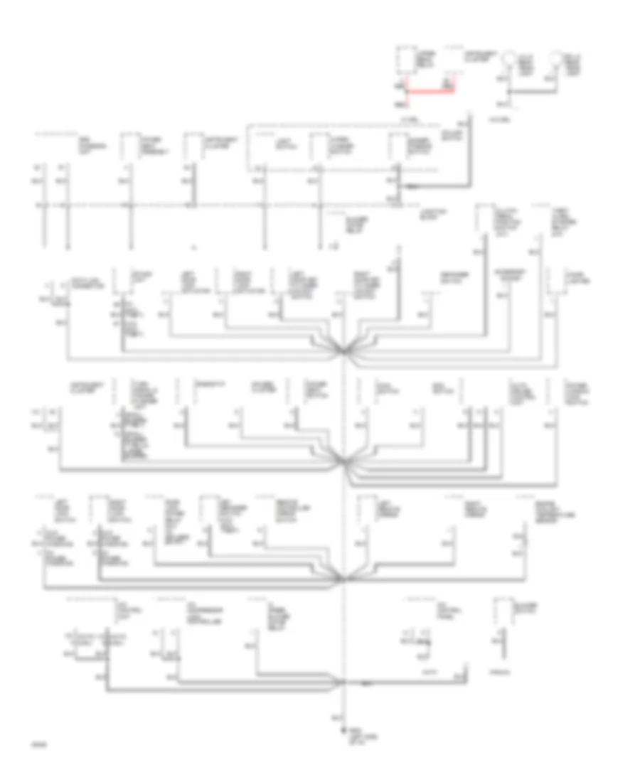
Ground Distribution Wiring Diagram (3 of 3) for Mitsubishi 3000GT VR-4 1994 3000
List of elements for Ground Distribution Wiring Diagram (3 of 3) for Mitsubishi 3000GT VR-4 1994 3000:
- (center rear of liftgate lid)
- (center rear of trunk)
- (forward of right rear wheelwell)
- (front left fender)
- (front right fender)
- (left front door sill)
- (not used)
- 1994 vftc c
- Abs control unit
- Active exhaust control module
- Active exhaust control switch
- Antenna motor control unit
- Brake fluid level switch
- Cd auto changer
- Con- denser fan motor
- Diode
- Door lock power relay no.1
- Drl control unit
- Electronic suspension control unit
- Fuel pump/ sender
- G100
- G101
- G309
- G401
- G407
- Hi speed radiator fan motor relay
- High mounted stop lights
- Hood switch
- Hydraulic unit
- Keyless entry control unit
- Left front park/ turn light
- Left front shock absorber
- Left horn
- Left rear shock absorber
- Left rear tail/ stop/ turn lights
- Lh backup light
- Lh fog light
- Lh hi beam head- light
- Lh license plate light
- Lh lo beam head- light
- Liftgate cylinder lock switch
- Liftgate switch
- Lo speed condenser fan motor relay
- Nca
- Radiator fan assembly
- Rear washer motor
- Resistor
- Rh backup light
- Rh fog light
- Rh hi beam head- light
- Rh license plate light
- Rh lo beam head- light
- Right front park/ turn light
- Right horn
- Right rear shock absorber
- Right rear tail/ stop/ turn lights
- Theft alarm horn
- W/ drl
- W/ fwd
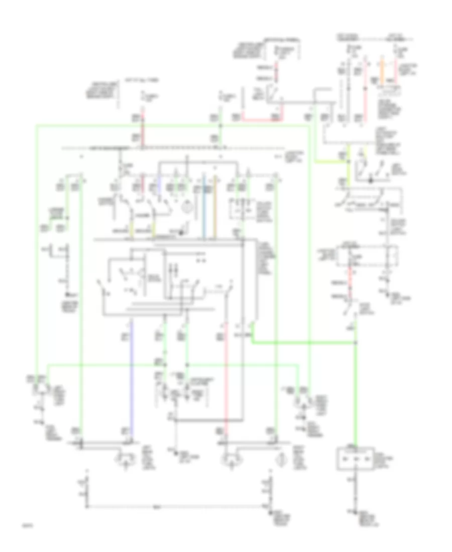
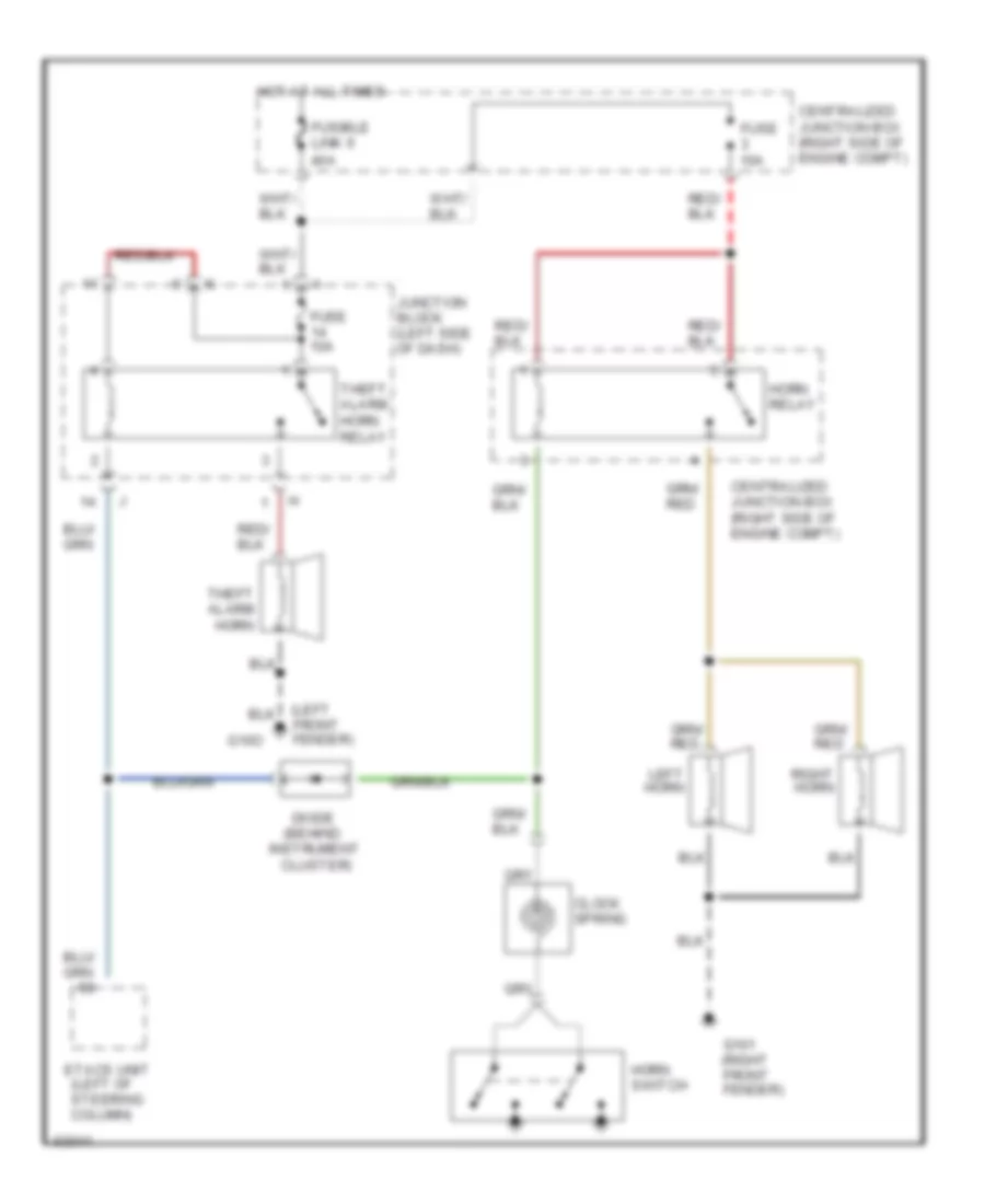
HEADLIGHTS
Fog Lamps Wiring Diagram for Mitsubishi 3000GT VR-4 1994 3000
List of elements for Fog Lamps Wiring Diagram for Mitsubishi 3000GT VR-4 1994 3000:
- (dimmer- passing switch)
- (etacs unit)
- (light switch)
- (rheostat)
- (right side of engine compt)
- Anti- theft system
- Centralized
- Centralized junction box (right side of engine compt)
- Column switch
- Exterior lights system
- Fender)
- Fog light relay
- Fog light switch
- Fuse 10a
- Fuse 15a
- Fusible link 3 40a
- G100 (left front
- G202 (left side
- Head
- Head- light relay
- Hot at all times
- Hot in run or start
- Illum.
- Interior lights system
- Interior lights system (taillight relay)
- Iod or storage connector (right eng. compt.)
- Junction block (left i/p)
- Junction box
- Left door switch
- Left fog light
- Light automatic shut-off unit (forward of left rear wheelwell)
- Of i/p)
- Off
- Red
- Right fog light
- Tail
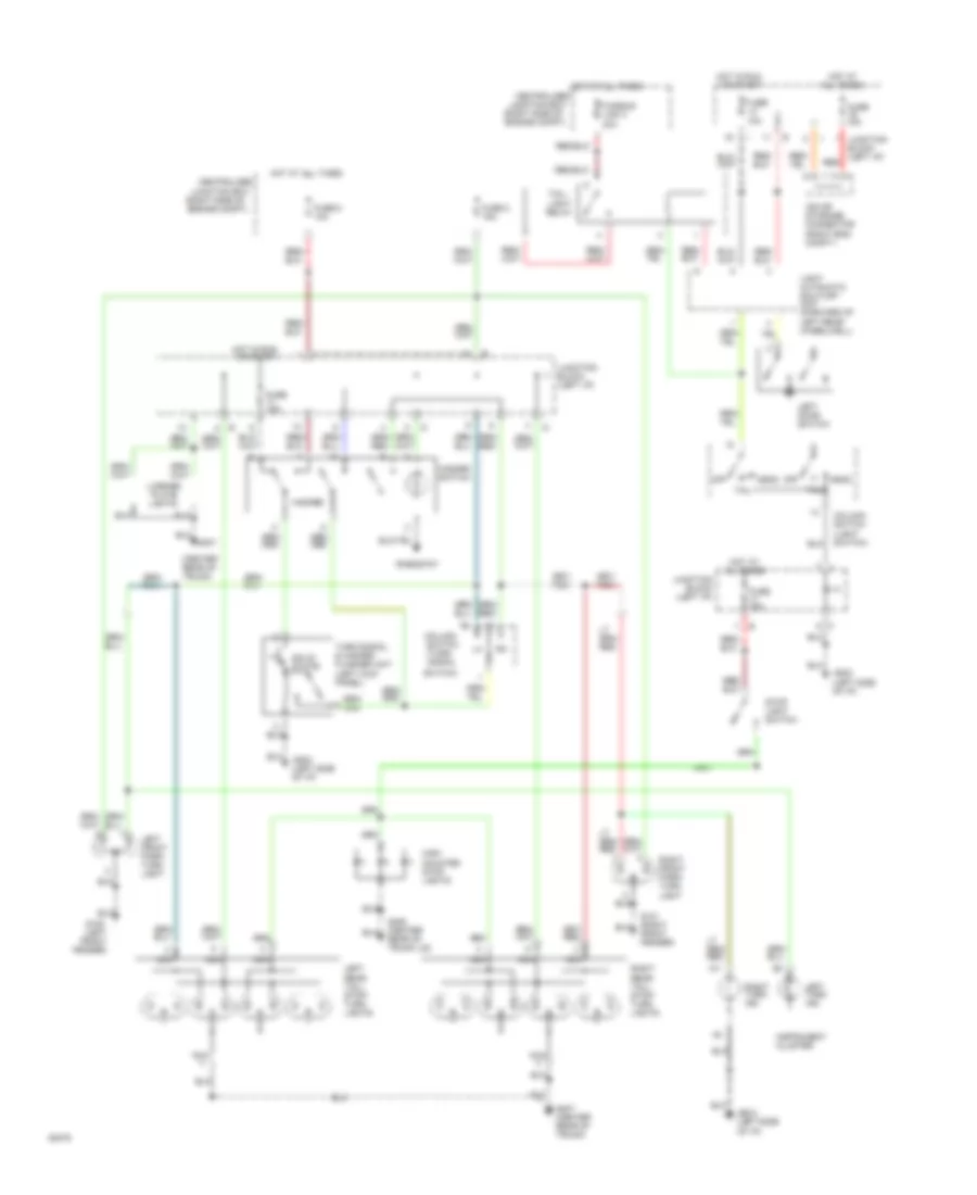
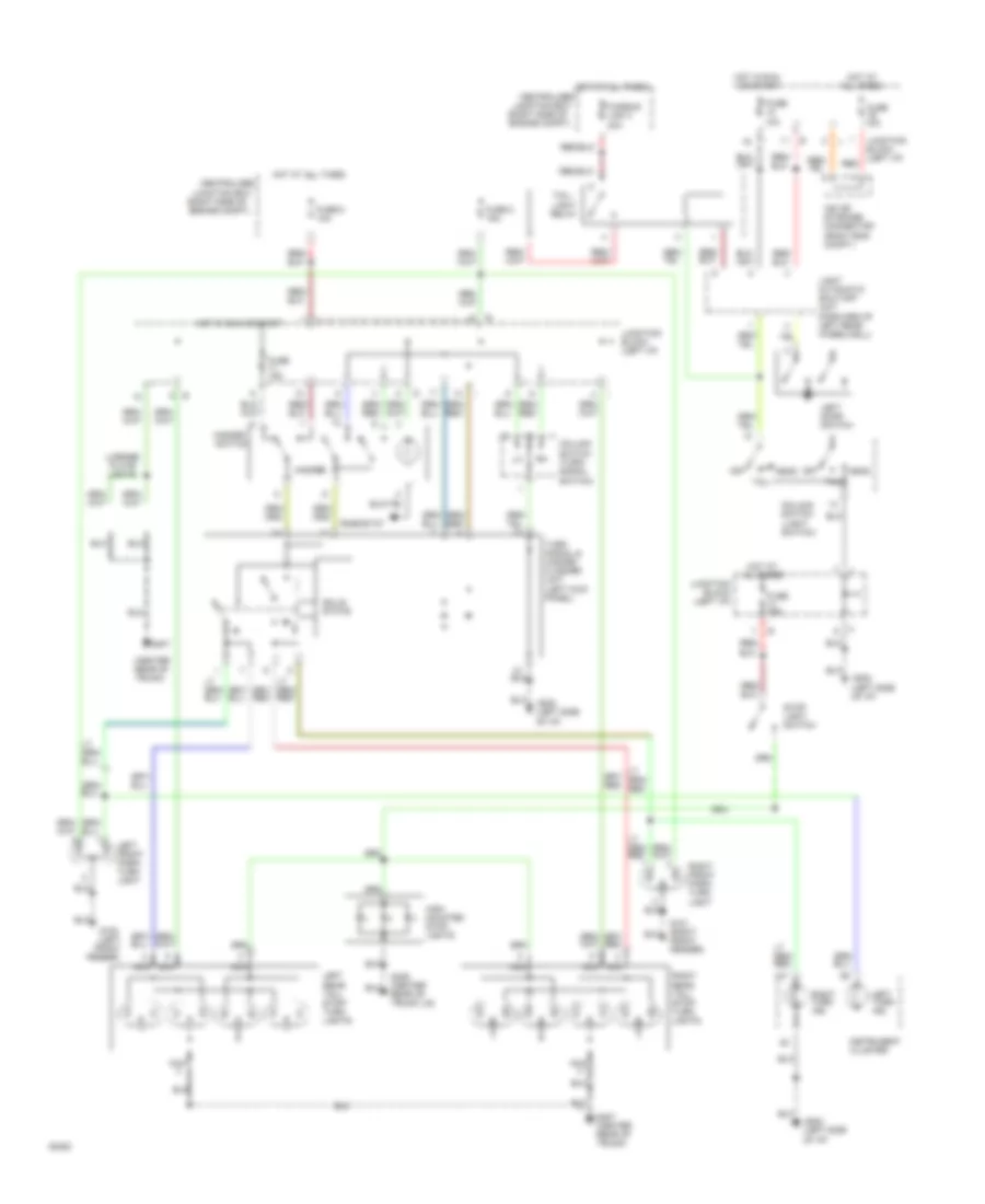
Headlamps Wiring Diagram for Mitsubishi 3000GT VR-4 1994 3000
List of elements for Headlamps Wiring Diagram for Mitsubishi 3000GT VR-4 1994 3000:
- (dimmer- passing switch)
- (light switch)
- (right side of engine compt)
- Centralized
- Centralized junction box (right side of engine compt)
- Cluster
- Column switch
- Data link connector (right of steering column)
- Etacs unit (left of steering column)
- Exterior lights system
- Fuse 10a
- Fuse 15a
- Fusible link 3 40a
- G202 (left side
- Head
- Head- light relay
- Hi beam ind.
- High beam head- light
- Hot at all times
- Hot in acc or run
- Hot in run or start
- Instrument
- Iod or storage connector (right eng. compt.)
- Junction block (left i/p)
- Junction box
- Left
- Left door switch
- Light automatic shut-off unit (forward of left rear wheelwell)
- Low beam head- light
- Of i/p)
- Off
- Red
- Right
- Tail
- With anti- theft
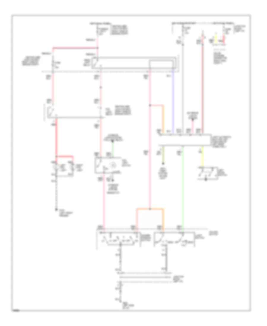
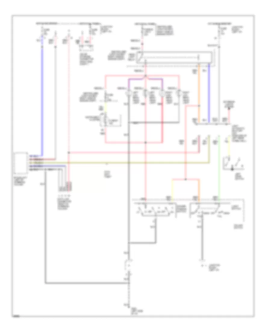
HORN
Horn Wiring Diagram, with Anti-theft for Mitsubishi 3000GT VR-4 1994 3000
List of elements for Horn Wiring Diagram, with Anti-theft for Mitsubishi 3000GT VR-4 1994 3000:
- (behind
- (left front fender)
- Centralized junction box (right side of engine compt)
- Clock spring
- Cluster)
- Diode
- Etacs unit (left of steering column)
- Fuse 10a
- Fusible link 6 40a
- G101 (right front fender)
- G10o
- Horn relay
- Horn switch
- Hot at all times
- Instrument
- Junction block (left side of dash)
- Left horn
- Right horn
- Theft alarm horn
- Theft alarm horn relay
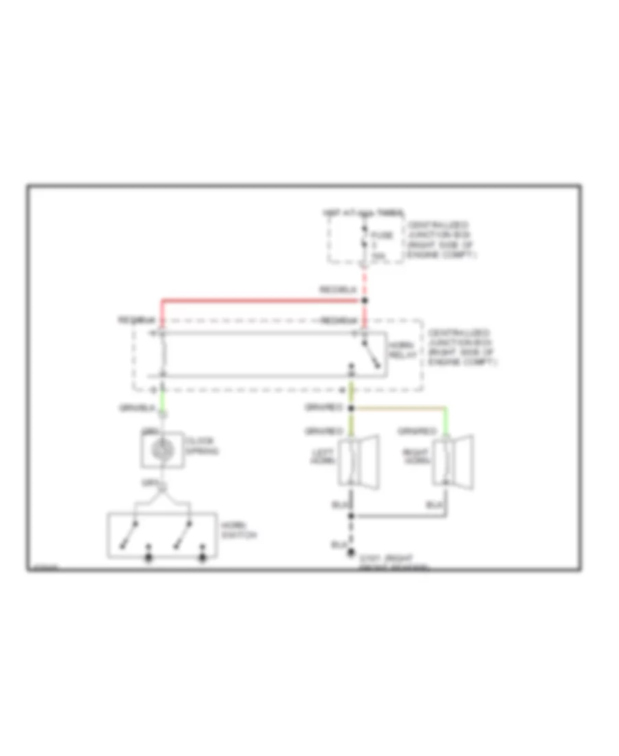
Horn Wiring Diagram, without Anti-theft for Mitsubishi 3000GT VR-4 1994 3000
List of elements for Horn Wiring Diagram, without Anti-theft for Mitsubishi 3000GT VR-4 1994 3000:
- (right
- Centralized junction box (right side of engine compt)
- Clock spring
- Fuse 10a
- G101 front fender)
- Horn relay
- Horn switch
- Hot at all times
- Left horn
- Right horn
INSTRUMENT CLUSTER
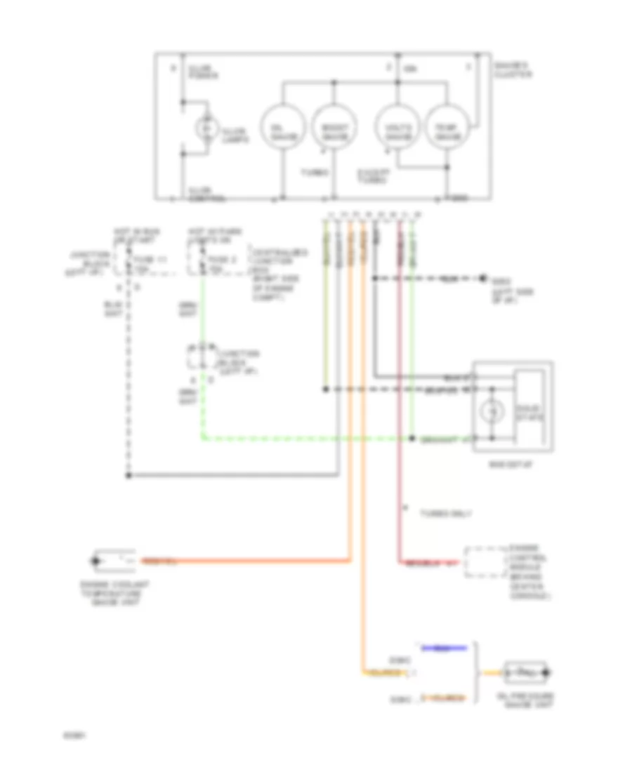
Gauges Wiring Diagram for Mitsubishi 3000GT VR-4 1994 3000
List of elements for Gauges Wiring Diagram for Mitsubishi 3000GT VR-4 1994 3000:
- (left i/p)
- (left side of i/p)
- Block
- Boost gauge
- Center console)
- Centralized junction box (right side
- Dohc
- Engine control module (behind
- Engine coolant
- Except turbo
- Fuse 11 15a
- Fuse 2 15a
- G202
- Gauges cluster
- Gnd
- Hot in run or start
- Hot w/ park lights on
- Ign
- Illum. control
- Illum. lamps
- Illum. power
- Junction
- Junction block (left i/p)
- Of engine compt)
- Oil gauge
- Oil pressure gauge unit
- Rheostat
- Sohc
- Solid state
- Temp. gauge
- Temperature gauge unit
- Turbo
- Turbo only
- Volts gauge
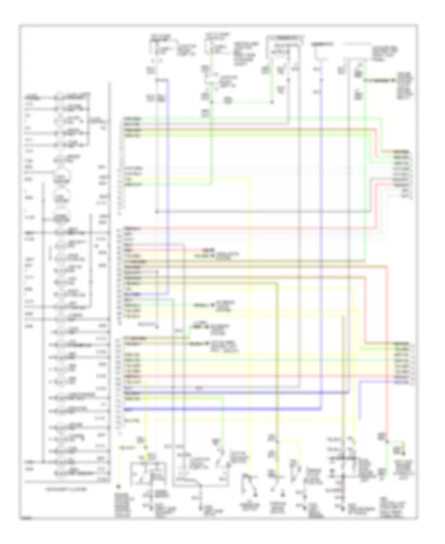
Indicators & Gauges Wiring Diagram (1 of 2) for Mitsubishi 3000GT VR-4 1994 3000
List of elements for Indicators & Gauges Wiring Diagram (1 of 2) for Mitsubishi 3000GT VR-4 1994 3000:
- (3000 gt)
- (mil)
- 4ws ind.
- A-1
- A-10
- A-11
- A-12
- A-13
- A-2
- A-3
- A-4
- Abs control unit (forward of
- Abs ind.
- Active aero control unit pin 2
- Active exhaust switch
- Aero ind.
- Anti-lock brakes system (hydraulic unit)
- Asc on ind.
- Auto-cruise control unit (right kick
- B-51
- B-52
- B-53
- B-54
- B-55
- B-56
- B-57
- B-58
- B-59
- B-60
- B-61
- B-62
- B-63
- B-64
- B-65
- B-66
- B-67
- Bat
- Brake fluid level switch
- Brake ind.
- Brake switch
- C-101
- C-102
- C-104
- C-105
- C-106
- C-107
- C-108
- C-109
- C-110
- C-111
- C-112
- C-114
- C-116
- Centralized junction box (right side
- Charge ind.
- Check engine ind.
- Control
- Cruise control system (auto- cruise
- Cruise ind.
- Door ajar ind.
- Engine controls system (engine control module)
- Exterior lights system
- Fuel gauge
- Fuel ind.
- Fuel pump/ fuel gauge sending unit
- Fuse 11 15a
- Fuse 2 15a
- G100 (left front fender)
- G123 (right side of safety wall)
- G202 (left side of i/p)
- G407 (center rear of trunk)
- Generator
- Gnd
- Headlights system
- Hi beam ind.
- Hot in run or start
- Hot w/ park lights on
- Ign
- Illum. control
- Illum. lamps (5 bulbs)
- Illum. power
- Instrument cluster
- Junction block (left i/p)
- Left turn ind.
- Low washer ind.
- Nca
- Od off ind.
- Of engine compt)
- Oil ind.
- Oil pressure switch
- Panel)
- Parking
- Power ind.
- Radiator ind.
- Red
- Relay)
- Rheostat
- Right rear wheelwell)
- Right turn ind.
- Seat belt ind.
- Security ind.
- Solid state
- Speed sensor
- Speed- ometer
- Sport ind.
- Srs ind.
- Tach- ometer
- Tour ind.
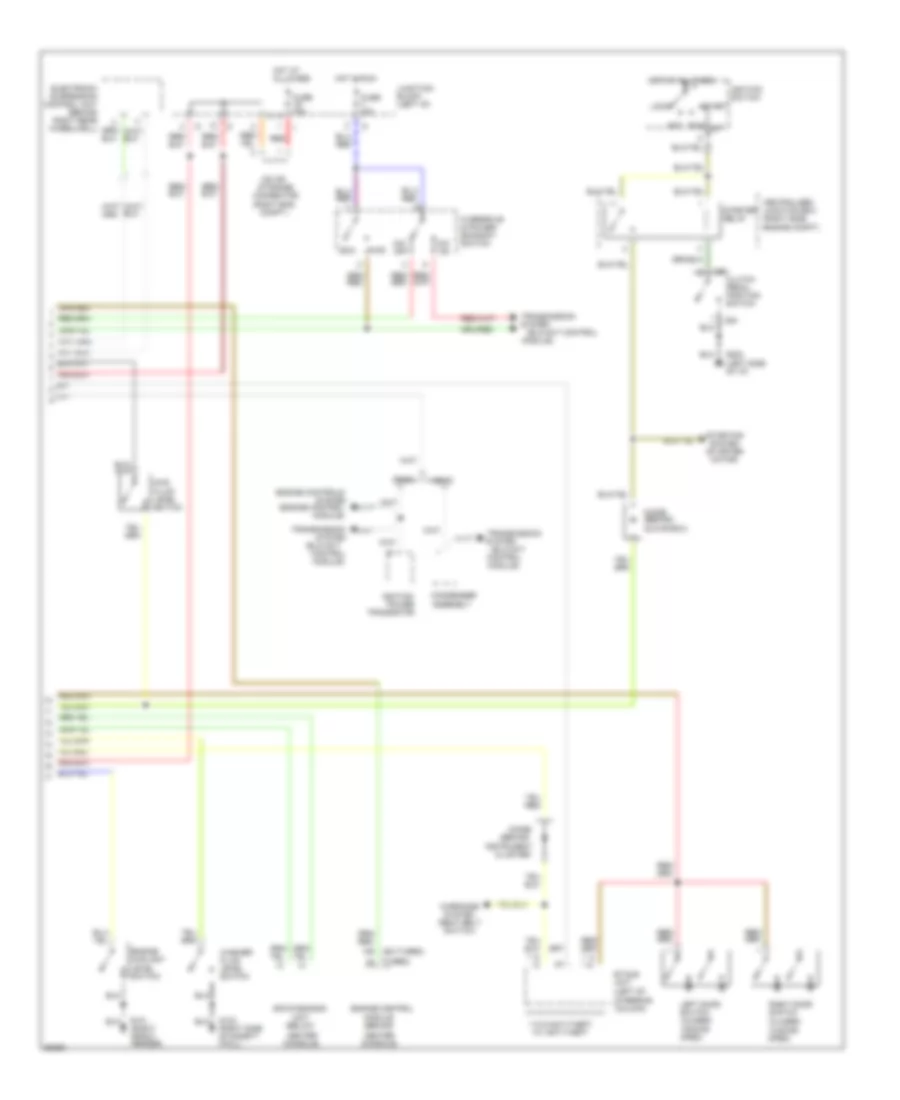
Indicators & Gauges Wiring Diagram (2 of 2) for Mitsubishi 3000GT VR-4 1994 3000
List of elements for Indicators & Gauges Wiring Diagram (2 of 2) for Mitsubishi 3000GT VR-4 1994 3000:
- (behind
- (below
- (elc-4a/t
- (elc-4a/t control
- (engine control
- (ex-turbo)
- (right eng. compt.)
- (turbo)
- ** *
- **w/o anti-theft
- *w/ anti-theft
- 4ws fluid level switch
- Acc
- C64
- Center
- Centralized junction box (right side engine compt)
- Cluster)
- Clutch pedal position switch
- Condenser assembly
- Connector
- Console)
- Control module)
- Diode
- Diode (behind
- Dohc
- Eco
- Engine control
- Engine controls
- Engine coolant level switch
- Etacs unit (left of
- Fuse 10a
- G101 (right front fender)
- G123 (right side of safety wall)
- G202 (left side of i/p)
- Glove box)
- Hot at all times
- Hot in run
- Ignition power
- Ignition switch
- Instrument
- Iod or storage
- Junction block (left i/p)
- Left door switch (closed w/door open)
- Lock
- Module (behind
- Module)
- O/d off
- O/d on
- Overdrive & power/ economy switch
- Pwr
- Red
- Right door switch (closed w/door open)
- Run
- Sir diagnosis
- Sohc
- Start
- Starter relay
- Starting system (starter motor)
- Steering column)
- System
- Transistor
- Transmission
- Unit
- Warnings system (seat belt switch)
- Washer fluid level switch
INTERIOR LIGHTS
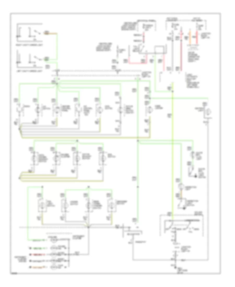
Courtesy Lamps Wiring Diagram for Mitsubishi 3000GT VR-4 1994 3000
List of elements for Courtesy Lamps Wiring Diagram for Mitsubishi 3000GT VR-4 1994 3000:
-
- * **
- * **
- *w/ anti-theft **w/o anti-theft
- Data link connector (right of steering column)
- Dome light assembly
- Dome lights
- Door
- Door ind.
- Door switch (closed w/door open)
- Etacs unit (left of steering column)
- Fuse 10a
- Fuse 15a
- G202 (left
- Hot at all times
- Hot in run or start
- Ignition key cylinder illum. light
- Instrument cluster
- Iod or storage connector (right eng. compt.)
- Junction block (left i/p)
- Left
- Left door light
- Left foot light
- Luggage compt light
- Luggage compt light switch
- Map lights
- Of i/p)
- Off
- Red
- Right
- Right door light
- Right foot light
- Side
- Timer
- W/o anti- theft
Instrument Illumination Wiring Diagram for Mitsubishi 3000GT VR-4 1994 3000
List of elements for Instrument Illumination Wiring Diagram for Mitsubishi 3000GT VR-4 1994 3000:
-
-
- (2)
- (5 bulbs)
- (light switch)
- (right side of engine compt)
- A/c control panel (auto a/c)
- A/c switch
- Active aero switch (3000 gt)
- Active exhaust switch
- All times
- Ashtray
- Centralized
- Cigar lighter
- Column switch
- Defogger switch
- Ecs switch
- Fog light switch
- Fuse 10a
- Fuse 2 15a
- Fusible link 3 40a
- G202 (left side
- Gauges cluster
- Glove box illum. light
- Glove box illum. light switch
- Hazard switch
- Head
- Heater control panel
- Hot at
- Hot at all times
- Hot in run or start
- Ill.
- Illumination
- Inspection light
- Inspection light switch
- Instrument cluster
- Instrument cluster system
- Iod or storage connector (right eng. compt.)
- Junction block (left i/p)
- Junction box
- Left vanity mirror light
- Light
- Light automatic shut-off unit (forward of left rear wheelwell)
- Main switch
- Nca
- O/d & power/ economy switch
- Od off ind.
- Of i/p)
- Off
- Power ind.
- Radio
- Rear wiper/ washer switch
- Red
- Rheostat
- Right vanity mirror light
- Solid state
- Sport ind.
- Tail
- Tail- light relay
- Tour ind.
PASSIVE RESTRAINTS
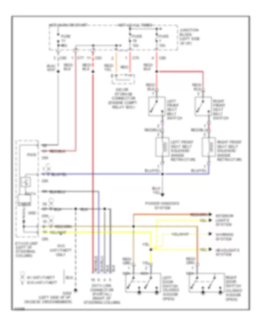
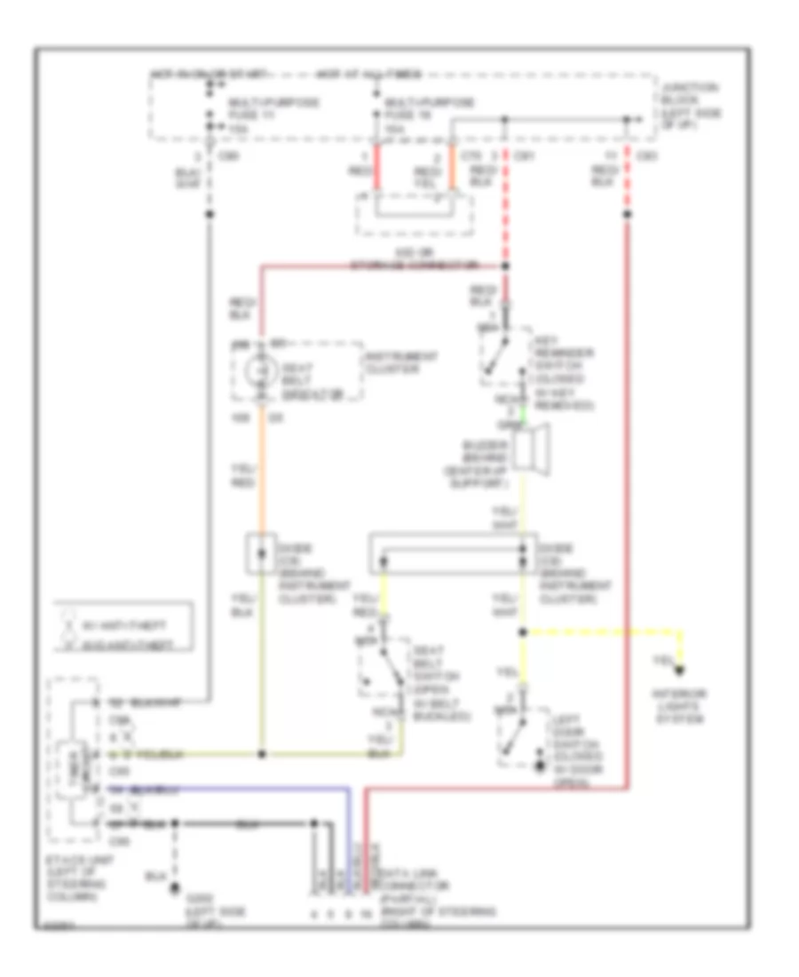
Electric Tension Reducer Wiring Diagram for Mitsubishi 3000GT VR-4 1994 3000
List of elements for Electric Tension Reducer Wiring Diagram for Mitsubishi 3000GT VR-4 1994 3000:
- (engine compt. relay box)
- C65
- C66
- C70
- C77
- C80
- C83
- Connector
- Data
- Data link connector (partial) (right of steering column)
- Etacs unit (left of steering column)
- Fuse 10a
- Fuse 15a
- G202 (left side of i/p, on deck crossmember)
- Gnd
- Headlights system
- Hot at all times
- Hot in 0n or start
- Interior lights system
- Iod or storage
- Junction block (left side of i/p)
- Left door switch (closed w/door open)
- Left front seat belt solenoid (inside retractor)
- Left front seat belt switch
- Nca
- Power windows system
- Pwr
- Red
- Right door switch (closed w/door open)
- Right front seat belt solenoid (inside retractor)
- Right front seat belt switch
- Timer
- W/ anti-theft
- W/o anti-theft
- W/o anti-theft only
- Warning system
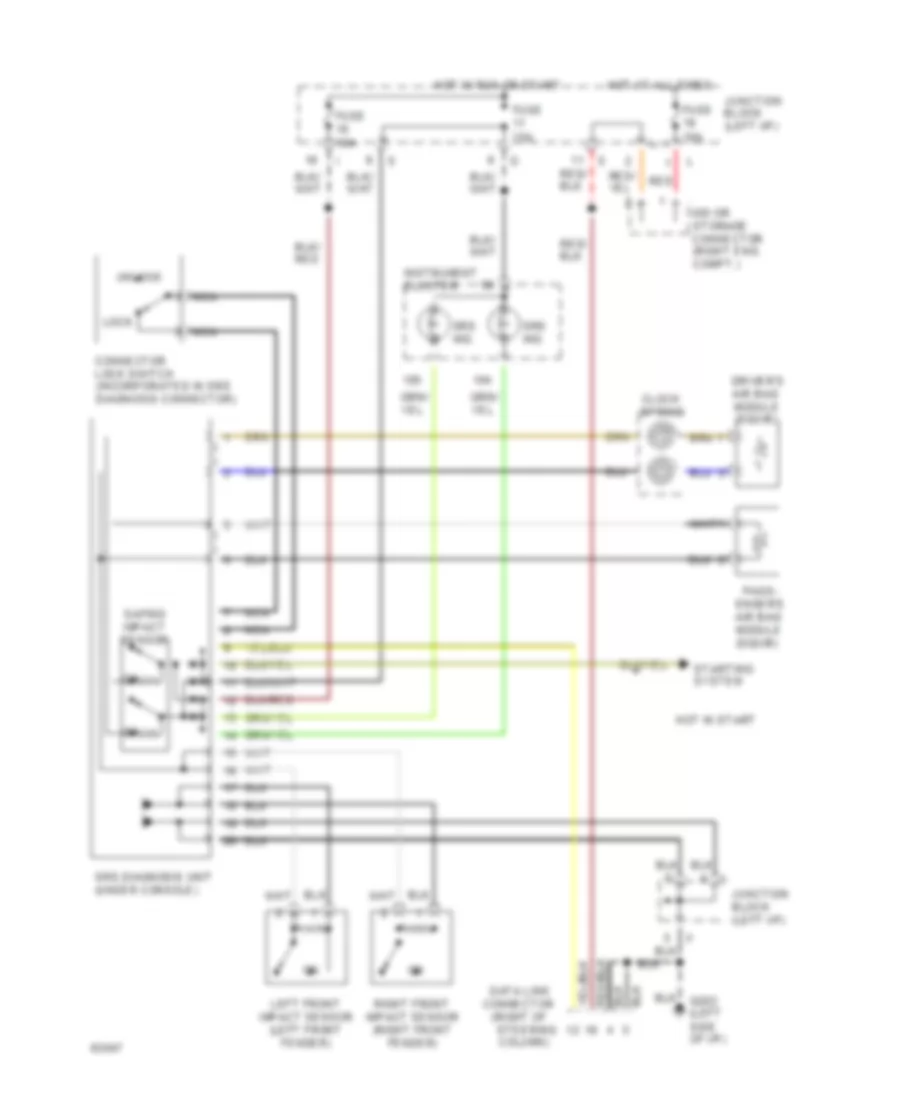
Passive Restraint Wiring Diagram for Mitsubishi 3000GT VR-4 1994 3000
List of elements for Passive Restraint Wiring Diagram for Mitsubishi 3000GT VR-4 1994 3000:
- (engine compt. relay box)
- C65
- C66
- C70
- C77
- C80
- C83
- Connector
- Data
- Data link connector (partial) (right of steering column)
- Etacs unit (left of steering column)
- Fuse 10a
- Fuse 15a
- G202 (left side of i/p, on deck crossmember)
- Gnd
- Headlights system
- Hot at all times
- Hot in 0n or start
- Interior lights system
- Iod or storage
- Junction block (left side of i/p)
- Left door switch (closed w/door open)
- Left front seat belt solenoid (inside retractor)
- Left front seat belt switch
- Nca
- Power windows system
- Pwr
- Red
- Right door switch (closed w/door open)
- Right front seat belt solenoid (inside retractor)
- Right front seat belt switch
- Timer
- W/ anti-theft
- W/o anti-theft
- W/o anti-theft only
- Warning system
POWER ANTENNA
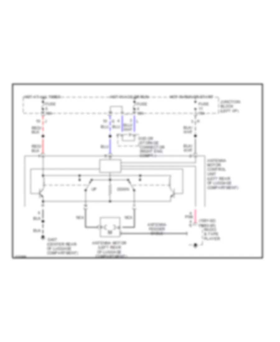
Power Antenna Wiring Diagram for Mitsubishi 3000GT VR-4 1994 3000
List of elements for Power Antenna Wiring Diagram for Mitsubishi 3000GT VR-4 1994 3000:
- (1991-92)
- (1993-95)
- (left rear of luggage compartment)
- Antenna feeder cable
- Antenna motor
- Antenna motor control unit (left rear of luggage compartment)
- Down
- Fuse 10a
- Fuse 15a
- G407 (center rear of luggage compartment)
- Hot at all times
- Hot in acc or run
- Hot in run or start
- Iod or storage connector (right eng. compt.)
- Junction block (left i/p)
- Nca
- Pnk
- Radio & tape player
POWER DISTRIBUTION
Power Distribution Wiring Diagram (1 of 3) for Mitsubishi 3000GT VR-4 1994 3000
List of elements for Power Distribution Wiring Diagram (1 of 3) for Mitsubishi 3000GT VR-4 1994 3000:
- (except
- (left side engine compt)
- (right side
- (turbo)
- 10a
- 120a
- 40a
- 4a/t control module
- 60a
- A/c compressor lock controller
- A/c control unit
- A/t
- Abs
- Abs power relay
- Alternator
- Auto a/c
- Auto- cruise control switch
- Auto-cruise control unit
- Backup light switch
- Battery
- Blower switch
- Canada
- Centralized
- Centralized junction box (right side engine compt)
- Clock spring
- Control
- Data link connector
- Dedicated fuse (left side of i/p)
- Defogger
- Defogger relay
- Dohc
- Door lights
- Drl
- Electronic suspension control unit
- Engine compt)
- Engine control module
- Fog light relay
- Foot lights
- Fuse
- Fuse 10a
- Fuse 15a
- Fuse 20a
- Fuse/ relay block
- Fuse/relay block
- Fusible link 1
- Fusible link 10 40a
- Fusible link 3
- Fusible link 4 30a
- Fusible link 5 40a
- Fusible link 6
- Fusible link 7
- Fusible link 9 30a
- G117-a/t (right rear of engine)
- G119-m/t (right front of engine)
- G123 (right side of safety wall)
- Head- light relay
- Headlights
- Hi speed blower
- Hi speed condenser fan relay
- Hi speed radiator fan relay
- Horn relay
- Hydraulic unit
- Instrument cluster
- Interior & exterior lights systems
- Junction box
- Keyless entry control unit
- Left
- Light automatic shut-off unit
- Lo speed condenser fan relay
- Lo speed radiator fan relay
- M/t
- Magnetic clutch relay
- Manual a/c
- Mfi relay
- Motor relay
- Park/ neutral position switch
- Power relay
- Power seat switch
- Power windows relay
- Radiator fan motor
- Radio
- Rear
- Red
- Remote mirror
- Right remote mirror
- Sohc
- Srs diagnosis unit
- Starter motor
- Tail light relay
- Turbo)
- Unit
Power Distribution Wiring Diagram (2 of 3) for Mitsubishi 3000GT VR-4 1994 3000
List of elements for Power Distribution Wiring Diagram (2 of 3) for Mitsubishi 3000GT VR-4 1994 3000:
- (left i/p)
- 4ws fluid level switch
- A/t
- Acc
- Auto-cruise control relay
- Blower motor relay
- Canada
- Cd changer
- Centralized junction box (right side engine compt)
- Column switch
- Dome light assembly
- Drl control unit
- Engine control module
- Etacs unit
- Front wiper motor
- Fuse
- Fuse 10a
- Fuse 15a
- Fuse 30a
- Gauges cluster
- Generator relay
- Hazard switch
- Ignition switch
- Instrument cluster
- Iod or storage connector
- Junction block
- Keyless entry control unit
- Lock
- M/t
- Main switch
- Park/ neutral position switch
- Radio
- Red
- Run
- Sohc & federal dohc w/o turbo only
- Speed sensor
- Srs diag- nosis unit
- Start
- Starter relay
- Stop light switch
- Theft- alarm horn relay
Power Distribution Wiring Diagram (3 of 3) for Mitsubishi 3000GT VR-4 1994 3000
List of elements for Power Distribution Wiring Diagram (3 of 3) for Mitsubishi 3000GT VR-4 1994 3000:
- (w/keyless entry)
- * **
- *sohc & dohc non-turbo (federal/canada) **turbo & dohc non-turbo (california)
- 4a/t control module
- A/t only
- Accessory
- Amplifier
- Antenna motor control unit
- Auto- cruise control unit
- Capacitor
- Cigar
- Condenser assembly
- Dohc
- Door lock relay no.1
- Door lock relay no.2
- Engine control module
- Etacs unit
- G202 (left side of i/p)
- Ignition coil
- Ignition coil 1-4
- Ignition coil 2-5
- Ignition coil 3-6
- Ignition key illumination light
- Ignition power transistor
- Instrument cluster
- Key reminder switch
- Left front seat belt switch
- Lighter
- Luggage comptartment light
- Mfi relay
- Nca
- O/d & power/ economy switch
- Park/ neutral position switch
- Rear intermittent wiper relay
- Rear wiper motor
- Rear wiper/ washer switch
- Remote controlled mirror switch
- Right front seat belt switch
- Socket
- Sohc
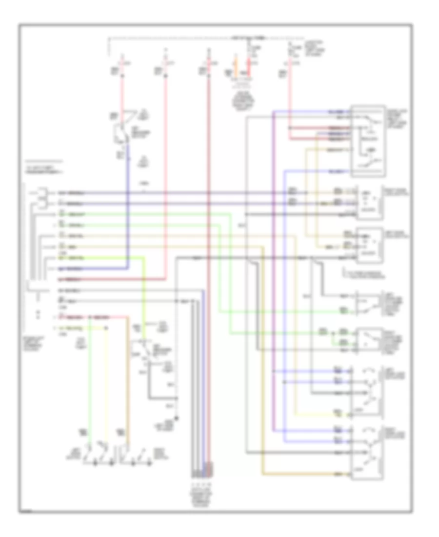
POWER DOOR LOCKS
Door Lock Wiring Diagram for Mitsubishi 3000GT VR-4 1994 3000
List of elements for Door Lock Wiring Diagram for Mitsubishi 3000GT VR-4 1994 3000:
- (1994)
- * **
- **** ***
- ***w/ pwr windows ****w/o pwr windows
- *w/ anti-theft **w/o anti-theft
- Anti- theft
- C-65
- C-66
- C-70
- C-77
- C-78
- C-81
- C-83
- Data link connector (right of steering column)
- Door lock power relay 1 (left side of dash)
- Etacs unit (left of steering column)
- Fuse 10a
- G202 (left side of dash)
- Hot at all times
- Iod or storage connector (right eng. compt.)
- Junction block (left side of dash)
- Key reminder switch
- Left door key cylinder unlock switch (1994)
- Left door lock actuator
- Left door lock switch
- Left door switch
- Lock
- N/a
- Off
- Red
- Right door key cylinder unlock switch (1994)
- Right door lock actuator
- Right door lock switch
- Right door switch
- Unlock
- W/o
- W/o anti- theft
Keyless Entry Wiring Diagram for Mitsubishi 3000GT VR-4 1994 3000
List of elements for Keyless Entry Wiring Diagram for Mitsubishi 3000GT VR-4 1994 3000:
- (forward of left rear wheelwell)
- (lh)
- (rh)
- * **
- **** ***
- ***w/ pwr windows ****w/o pwr windows
- *w/ anti-theft **w/o anti-theft
- Anti- theft
- C-65
- C-66
- Data link connector (right of steering column)
- Dome lights
- Door lock power relay 1 (left side of dash)
- Door lock power relay 2 (forward of left rear wheelwell)
- Etacs unit (left of steering column)
- Feeder antenna
- Foot lights
- Fuse 10a
- Fuse 15a
- G202 (left side of dash)
- G407 (center rear of trunk)
- Hot at all times
- Hot in acc or run
- Iod or storage connector
- Junction block (left side of dash)
- Key reminder switch
- Keyless entry control unit
- Left door lock actuator
- Left door lock switch
- Left door switch
- Lock
- Red
- Right door lock actuator
- Right door switch
- Timer
- Unlock
- W/o
- W/o anti- theft
- With
POWER MIRRORS
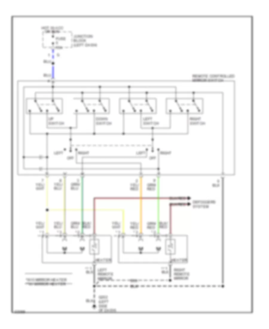
Power Mirror Wiring Diagram for Mitsubishi 3000GT VR-4 1994 3000
List of elements for Power Mirror Wiring Diagram for Mitsubishi 3000GT VR-4 1994 3000:
- * **
- *w/o mirror heater **w/ mirror heater
- Defoggers system
- Down switch
- Fuse 15a
- G202 (left side of dash)
- Heater
- Hot in acc
- Junction block (left dash)
- Left
- Left remote mirror
- Left switch
- Off
- Or run
- Remote controlled mirror switch
- Right
- Right remote mirror
- Right switch
- Up switch
POWER SEATS
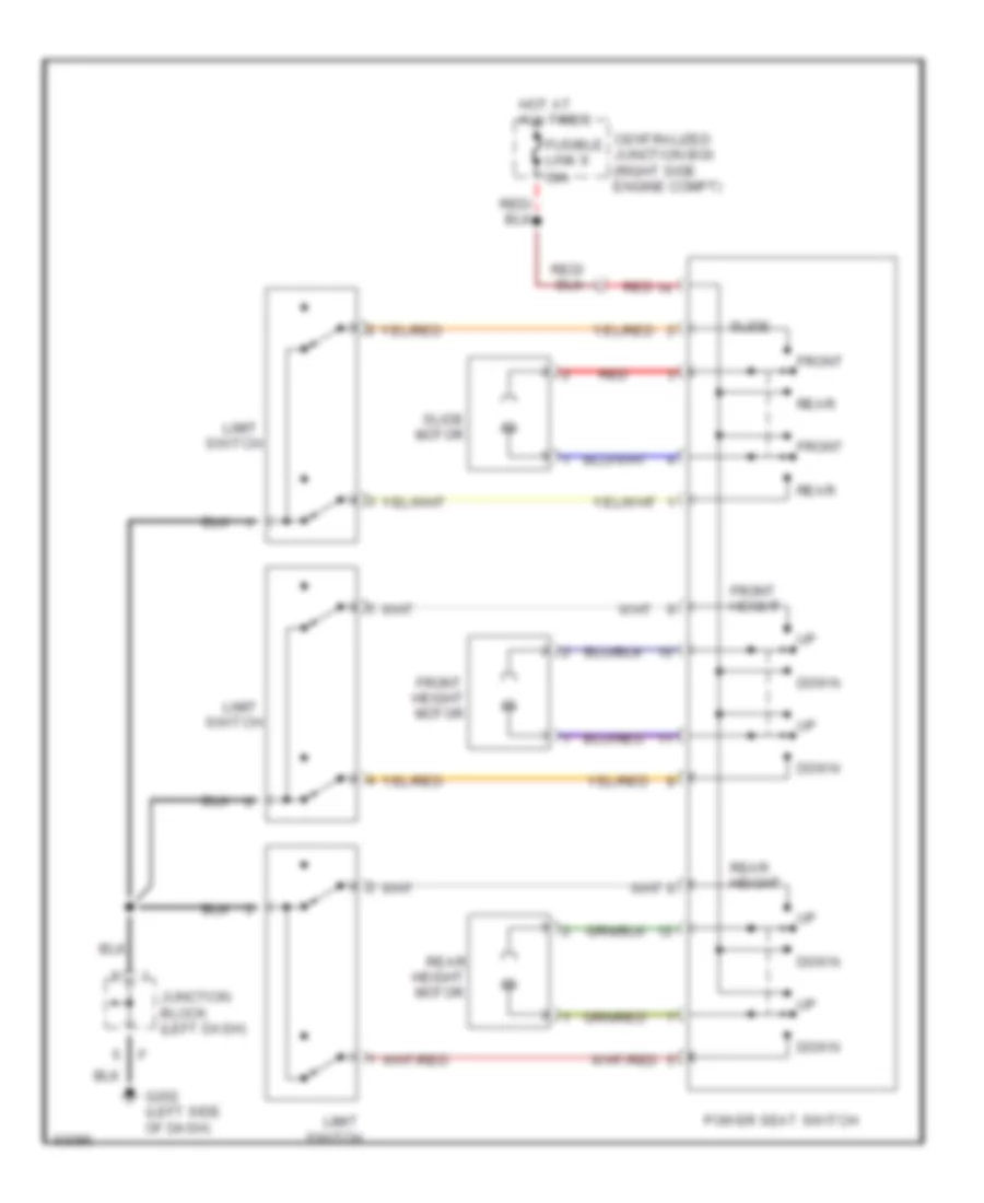
6-Way Power Seat Wiring Diagram for Mitsubishi 3000GT VR-4 1994 3000
List of elements for 6-Way Power Seat Wiring Diagram for Mitsubishi 3000GT VR-4 1994 3000:
- Centralized junction box (right side engine compt)
- Down
- Front
- Front height
- Front height motor
- Fusible link 9 30a
- G202 (left side of dash)
- Height motor
- Hot at all times
- Junction block (left dash)
- Limit
- Motor
- Power seat switch
- Rear
- Rear height
- Red
- Slide
- Switch
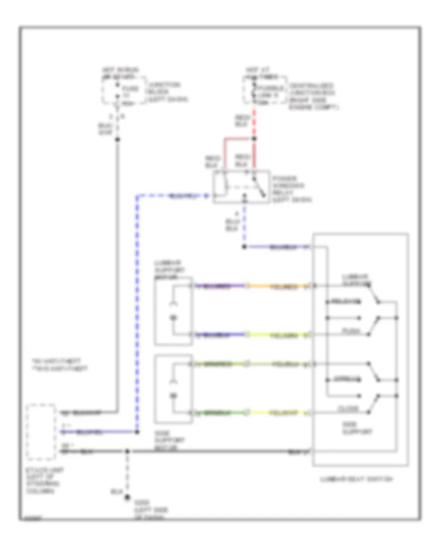
Power Lumbar Seat Wiring Diagram for Mitsubishi 3000GT VR-4 1994 3000
List of elements for Power Lumbar Seat Wiring Diagram for Mitsubishi 3000GT VR-4 1994 3000:
- * **
- *w/ anti-theft **w/o anti-theft
- Centralized junction box (right side engine compt)
- Close
- Etacs unit (left of steering column)
- Fuse 15a
- Fusible link 9 30a
- G202 (left side of dash)
- Hot at all times
- Hot in run or start
- Junction block (left dash)
- Lumbar seat switch
- Lumbar support
- Lumbar support motor
- Power windows relay (left dash)
- Push
- Release
- Side support
- Side support motor
- Spread
POWER WINDOWS
Power Window Wiring Diagram for Mitsubishi 3000GT VR-4 1994 3000
List of elements for Power Window Wiring Diagram for Mitsubishi 3000GT VR-4 1994 3000:
-
- * **
- *w/ anti-theft **w/o anti-theft
- Centralized junction box (right side engine compt)
- Data link connector (right of steering column)
- Down
- Down circuit
- Etacs unit (left of steering column)
- Fuse 10a
- Fuse 15a
- Fusible link 9 30a
- G202 (left side of i/p)
- Hot at all times
- Hot in run or start
- Iod or storage connector (right engine compt.)
- Junction block (left i/p)
- Left door switch (closed w/door open)
- Left window motor
- Lock switch
- One touch
- Power window main switch
- Power window sub switch
- Power windows relay (left i/p)
- Red
- Right door switch (closed w/door open)
- Right window motor
- Timer
- W/o anti- theft only
RADIO
Radio Wiring Diagrams, with Amplifier for Mitsubishi 3000GT VR-4 1994 3000
List of elements for Radio Wiring Diagrams, with Amplifier for Mitsubishi 3000GT VR-4 1994 3000:
- 1996 vftc c
- Amplifier
- Antenna feeder cable
- C70
- C77
- C78
- C80
- C81
- C83
- Cd auto changer
- Clock spring (in steering wheel)
- Criuise control system
- D36
- D47
- Din cable
- G307 (below right rear window)
- G407 (below trunk latch)
- Glass antenna
- Ground
- Hot at all times
- Hot in acc & run
- Hot in run & start
- Interior lights system
- Iod or storage connector (in engine compt) relay box)
- Junction block (under left side of dash)
- Left door speaker
- Left front speaker
- Left rear speaker
- Motor antenna
- Motor antenna control unit (behind left rear quarter panel)
- Multi- purpose fuse 11 15a
- Multi- purpose fuse 13 15a
- Multi- purpose fuse 19 10a
- Multi- purpose fuse 4 10a
- Multi- purpose fuse 6 10a
- Nca
- Pnk
- Radio & tape player
- Radio remote control switch
- Red
- Right door speaker
- Right front speaker
- Right rear speaker
Radio Wiring Diagrams, without Amplifier for Mitsubishi 3000GT VR-4 1994 3000
List of elements for Radio Wiring Diagrams, without Amplifier for Mitsubishi 3000GT VR-4 1994 3000:
- 1994-1996
- 1996 vftc c
- 1997-1999
- Antenna feeder cable
- C70
- C77
- C78
- C80
- C81
- C83
- Cd auto changer
- Clock spring (in steering wheel)
- Criuise control system
- D36
- D47
- Din cable
- G307 (below right rear window)
- G407 (below trunk latch)
- Glass antenna
- Hot at all times
- Hot in acc & run
- Hot in run & start
- Interior lights system
- Iod or storage connector (in engine compt) relay box)
- Junction block (under left side of dash)
- Left door speaker
- Left front speaker
- Left rear speaker
- Motor antenna
- Motor antenna control unit (behind left rear quarter panel)
- Multi- purpose fuse 11 15a
- Multi- purpose fuse 19 10a
- Multi- purpose fuse 4 10a
- Multi- purpose fuse 6 10a
- Nca
- Pnk
- Radio & tape player
- Radio remote control switch
- Red
- Right door speaker
- Right front speaker
- Right rear speaker
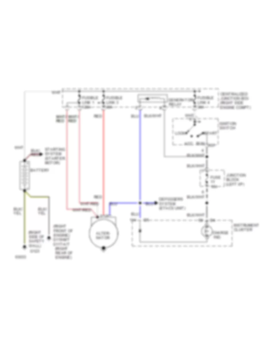
STARTING/CHARGING
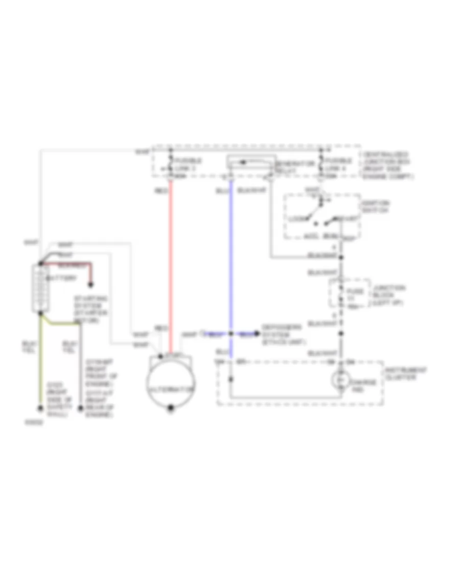
Charging Wiring Diagram, DOHC for Mitsubishi 3000GT VR-4 1994 3000
List of elements for Charging Wiring Diagram, DOHC for Mitsubishi 3000GT VR-4 1994 3000:
- (right front of engine) g119-m/t g117-a/t
- (right rear of engine)
- (right side of safety wall)
- 120a
- 40a
- Acc
- Alter- nator
- Battery
- Centralized junction box (right side engine compt)
- Charge
- Defoggers system (etacs unit)
- Fuse 15a
- Fusible link 1
- Fusible link 3
- Fusible link 4 30a
- G123
- Generator
- Ig1
- Ignition switch
- Ind.
- Instrument cluster
- Junction block (left i/p)
- Lock
- Red
- Relay
- Run
- Start
- Starting system (starter motor)
Charging Wiring Diagram, SOHC for Mitsubishi 3000GT VR-4 1994 3000
List of elements for Charging Wiring Diagram, SOHC for Mitsubishi 3000GT VR-4 1994 3000:
- 40a
- Acc
- Alternator
- Battery
- Centralized junction box (right side engine compt)
- Charge
- Defoggers system (etacs unit)
- Fuse 15a
- Fusible link 3
- Fusible link 4 30a
- G117-a/t (right rear of engine)
- G119-m/t (right front of engine)
- G123 (right side of safety wall)
- Generator
- Ig1
- Ignition switch
- Ind.
- Instrument cluster
- Junction block (left i/p)
- Lock
- Red
- Relay
- Run
- Start
- Starting system (starter motor)
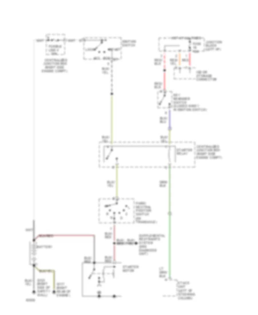
Starting Wiring Diagram, A/T with Anti-Theft for Mitsubishi 3000GT VR-4 1994 3000
List of elements for Starting Wiring Diagram, A/T with Anti-Theft for Mitsubishi 3000GT VR-4 1994 3000:
- (left of steering column)
- (on transaxle)
- (right side
- 30a
- Acc
- Battery
- Centralized junction box
- Centralized junction box (right side engine compt)
- Engine compt)
- Etacs unit
- Fuse 10a
- Fusible link 4
- G117 (right rear of engine)
- G123 (right side of safety wall)
- Hot at all times
- Ignition switch
- Iod or storage connector
- Junction block (left i/p)
- Key reminder switch (closed w/key in ignition switch)
- Lock
- Park/ neutral position switch
- Red
- Run
- Start
- Starter motor
- Starter relay
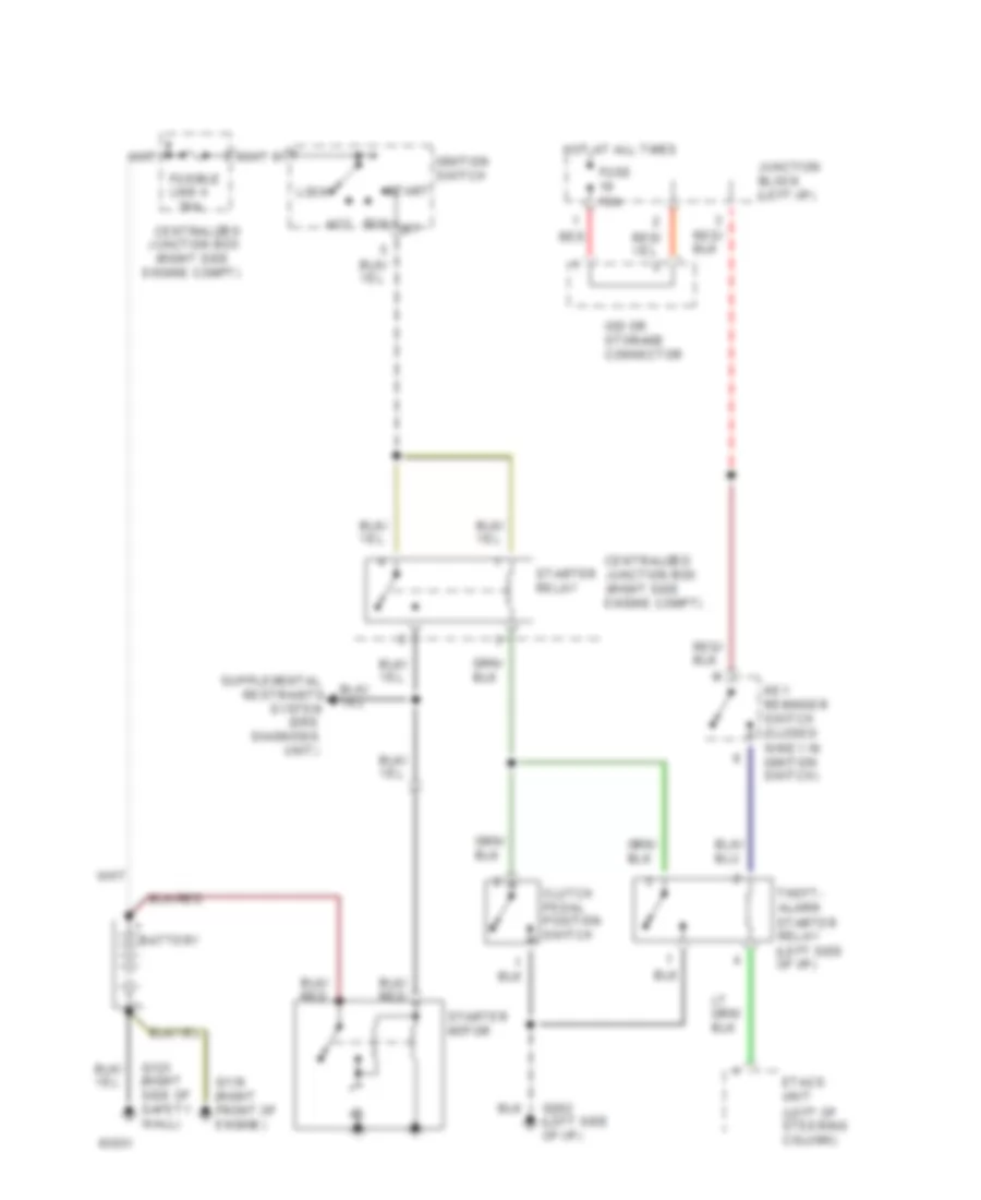
Starting Wiring Diagram, M/T with Anti-Theft for Mitsubishi 3000GT VR-4 1994 3000
List of elements for Starting Wiring Diagram, M/T with Anti-Theft for Mitsubishi 3000GT VR-4 1994 3000:
- (left of steering column)
- (right side
- (srs
- 30a
- Acc
- Battery
- Centralized junction box
- Centralized junction box (right side engine compt)
- Clutch pedal position switch
- Diagnosis
- Engine compt)
- Etacs unit
- Fuse 10a
- Fusible link 4
- G119 (right front of engine)
- G123 (right side of safety wall)
- G202 (left side of i/p)
- Hot at all times
- Ignition switch
- Iod or storage connector
- Junction block (left i/p)
- Key reminder switch (closed w/key in ignition switch)
- Lock
- Red
- Restraints
- Run
- Start
- Starter motor
- Starter relay
- Starter relay (left side of i/p)
- System
- Theft- alarm
- Unit)
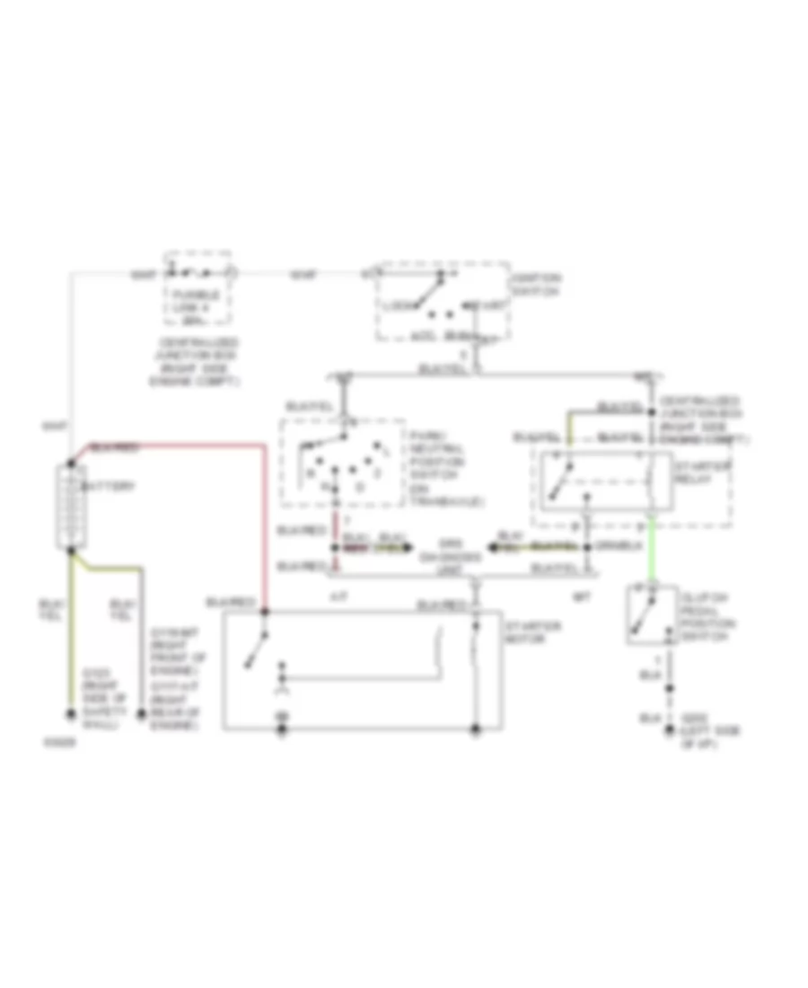
Starting Wiring Diagram, without Anti-theft for Mitsubishi 3000GT VR-4 1994 3000
List of elements for Starting Wiring Diagram, without Anti-theft for Mitsubishi 3000GT VR-4 1994 3000:
- (on transaxle)
- (right side
- 30a
- A/t
- Acc
- Battery
- Centralized junction box
- Centralized junction box (right side engine compt)
- Clutch pedal position switch
- Engine compt)
- Fusible link 4
- G117-a/t (right rear of engine)
- G119-m/t (right front of engine)
- G123 (right side of safety wall)
- G202 (left side of i/p)
- Ignition switch
- Lock
- M/t
- Park/ neutral position switch
- Run
- Srs diagnosis unit
- Start
- Starter motor
- Starter relay
SUPPLEMENTAL RESTRAINTS
Supplemental Restraint Wiring Diagram for Mitsubishi 3000GT VR-4 1994 3000
List of elements for Supplemental Restraint Wiring Diagram for Mitsubishi 3000GT VR-4 1994 3000:
-
- (right of steering column)
- Air bag module (squib)
- Clock spring
- Connector
- Connector lock switch (incorporated in srs diagnosis connector)
- Data link
- Driver's air bag module (squib)
- Fuse 10a
- Fuse 15a
- G202 (left side of i/p)
- Hot at all times
- Hot in run or start
- Hot in start
- Instrument cluster
- Iod or storage connector (right eng. compt.)
- Junction block (left i/p)
- Left front impact sensor (left front fender)
- Lock
- Nca
- Pass- enger's
- Red
- Right front impact sensor (right front fender)
- Safing impact sensor
- Srs diagnosis unit (under console)
- Srs ind.
- Starting system
- Unlock
TRANSMISSION
Transmission Wiring Diagram for Mitsubishi 3000GT VR-4 1994 3000
List of elements for Transmission Wiring Diagram for Mitsubishi 3000GT VR-4 1994 3000:
- (left side of dash)
- 4 a/t control module (behind center of dash)
- 4-speed a/t solenoid valve
- A/c relay sig
- A/t fluid temp sensor (on valve body)
- Air conditioning system (thermostat switch)
- Auto-cruise control unit (right kick panel)
- Back-up lts
- C70
- C77
- C81
- Data link connector (below left side of dash)
- Dedicated fuse 2 (j/b)
- Dlc mode ctrl
- Dlc output
- Ecm pin 71
- Economy
- Eng comm sig
- Engine controls system (condenser assembly)
- Engine controls system (ecm)
- Fuse 18 10a
- Fuse 19 10a
- Fuse 7 10a
- G123 (right side of safety wall)
- G123 (safety wall behind battery)
- G206 (below center of dash panel)
- G302 (right front side of center console)
- Gnd
- Hot at all times junction block
- Hot in run
- Hot in run or start
- Ign pulse
- Ignition switch
- Illum
- Instrument cluster
- Kickdown servo sw
- Kickdown servo switch (on transaxle)
- Nca
- Nca nca
- O/d sw
- Off
- Oil pressure control solenoid
- Oil temp sen
- Overdrive and power/economy switch
- Park/neutral position switch (on transaxle at linkage)
- Pin 46
- Pin 60
- Pin 7
- Pnk
- Power nca
- Press ctrl sol vlv
- Pulse gen a
- Pulse gen b
- Pulse generators (right side of engine, on transaxle)
- Pwr mode sig
- Pwr source
- Pwr source backup
- R n
- Red
- Rheostat
- Sensor gnd
- Shift control solenoid a
- Shift control solenoid b
- Shift ctrl sol
- Shift ctrl sol vlv
- Speed sensor (reed sw)
- Starter motor
- Starter relay
- Storage connector (left side of dash)
- Tcc sol
- Throt pos sen
- Throttle position sensor (throttle body)
- Torque converter clutch sol valve
- Veh spd reed sw
- W/ auto- cruise
- W/ theft- alarm
- W/o auto- cruise
- W/o theft- alarm
WARNING SYSTEMS
Warning System Wiring Diagrams for Mitsubishi 3000GT VR-4 1994 3000
List of elements for Warning System Wiring Diagrams for Mitsubishi 3000GT VR-4 1994 3000:
- Buzzer (behind center i/p support)
- C65
- C66
- C70
- C80
- C81
- C83
- Data link connector (partial) (right of steering column)
- Diode (c8) (behind instrument cluster)
- Diode (c9) (behind instrument cluster)
- Etacs unit (left of steering column)
- G202 (left side of i/p)
- Hot at all times
- Hot in on or start
- Instrument cluster
- Interior lights system
- Iod or storage connector
- Junction block (left side of i/p)
- Key reminder switch (closed w/ key removed)
- Left door switch (closed w/ door open)
- Multi-purpose fuse 11 15a
- Multi-purpose fuse 19 10a
- Nca
- Red
- Seat belt indicator
- Seat belt switch (open w/ belt buckled)
- Timer circuit
- W/ anti-theft
- W/o anti-theft
WIPER/WASHER
Front Wiper/Washer Wiring Diagram for Mitsubishi 3000GT VR-4 1994 3000
List of elements for Front Wiper/Washer Wiring Diagram for Mitsubishi 3000GT VR-4 1994 3000:
- (left dash)
- (left side
- (right side safety wall) g123
- Block
- Column switch
- Data link connector (right of steering column)
- Etacs unit (left of steering column)
- Fast
- Front washer motor (near battery)
- Front wiper motor (right rear of eng compt)
- Fuse 15a
- G202
- Hot in acc or run
- Int
- Intermit- tent time detection circuit
- Intermittent
- Junction
- Junction block (left dash)
- Of dash)
- Off
- Slow
- Timer circuit
- W/ anti-theft w/o anti-theft
- Washer switch
- Washer switch on interval detector circuit
- Wiper relay
- Wiper switch
Rear Wiper/Washer Wiring Diagram for Mitsubishi 3000GT VR-4 1994 3000
List of elements for Rear Wiper/Washer Wiring Diagram for Mitsubishi 3000GT VR-4 1994 3000:
- (left side
- (right rear corner of luggage compt) rear washer motor
- Fuse 15a
- G202
- G407 (center rear of trunk)
- Hot in acc
- Illumination
- Int
- Interior lights system
- Junction block (left i/p)
- Of i/p)
- Off
- Or run
- Rear intermittent wiper relay (behind left quarter trim panel)
- Rear wiper motor (behind panel, on rear deck lid)
- Rear wiper/
- Washer switch
- Wiper switch

 Čeština
 Dansk
Dansk Deutsch
 Ελληνικά
 English
 English
 Español
 Suomi
Suomi Français
 Français
 עברית
עברית Hrvatski
 Magyar
 Italiano
 日本語
日本語 한국어
한국어 Nederlands
 Polski
 Português
 Português
 Română
 Slovenčina
 Slovenščina
 Svenska
 Türkçe
 中文 (中国)