AIR CONDITIONING
A/C Wiring Diagram for Suzuki Swift 1997
 https://portal-diagnostov.com/license.html
Automotive Electricians Portal FZCO
Automotive Electricians Portal FZCO
https://portal-diagnostov.com/license.html
https://portal-diagnostov.com/license.html
Automotive Electricians Portal FZCO
Automotive Electricians Portal FZCO
List of elements for A/C Wiring Diagram for Suzuki Swift 1997:
- 1995 vftc c
- A/c 1 relay
- A/c 2 relay
- A/c amplifier (below right side of i/p)
- A/c compressor clutch
- A/c condenser fan motor
- A/c off
- A/c relay
- A/c req
- A/c switch
- Blower motor
- Blower motor resistor (behind right side of i/p)
- Blower speed selector switch
- C21
- C23
- Dual pres sw
- Dual pressure switch (right rear of engine compartment)
- E22
- E23
- E62
- Engine controls system
- Evap temp
- Evaporator thermistor (behind right side of i/p)
- Fuse 21 15a
- Fuse 22 20a
- Fuse 4 30a
- Fuse 7 15a
- G01
- G100 (left front of engine compt)
- G101 (right front of engine compt)
- G20
- G200 (left kick panel)
- G206 (center of i/p)
- G31
- Ground
- Hot at all times
- Hot in on
- Hot in on or start
- Idle up
- Idle-up
- Ign
- Interior lights system
- J/b
- Main fuse box
- Off
- Pnk
- Powertrain or engine control module (behind right side of i/p, near glove box)
- Radiator fan motor
- Rdtr fan relay
- Relay box
- Relay ctrl
- Sensor ground
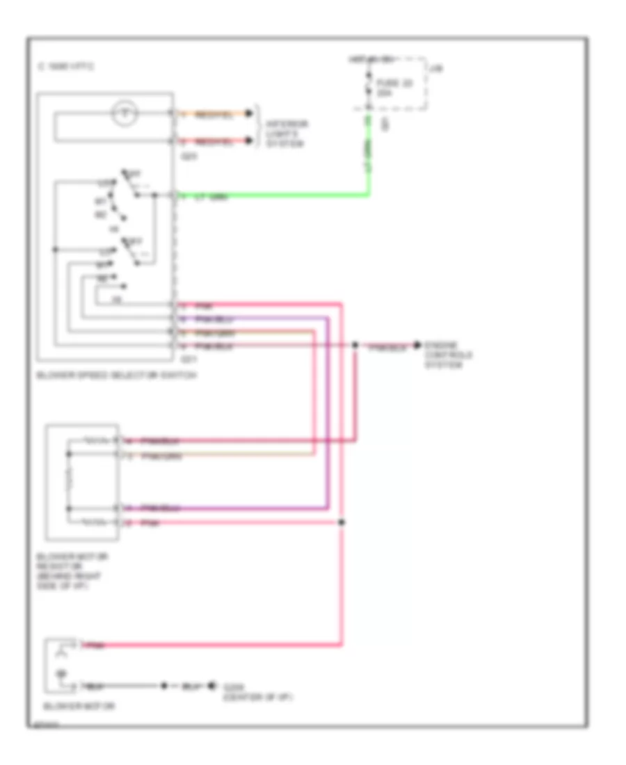
Heater Wiring Diagram for Suzuki Swift 1997
List of elements for Heater Wiring Diagram for Suzuki Swift 1997:
- 1995 vftc c
- Blower motor
- Blower motor resistor (behind right side of i/p)
- Blower speed selector switch
- Engine controls system
- Fuse 22 20a
- G01
- G20
- G206 (center of i/p)
- G31
- Hot in on
- Interior lights system
- J/b
- Off
- Pnk
ANTI-LOCK BRAKES
Anti-lock Brake Wiring Diagrams for Suzuki Swift 1997
List of elements for Anti-lock Brake Wiring Diagrams for Suzuki Swift 1997:
- (left kick panel)
- Abs active ind
- Abs check relay (left side of dash)
- Abs control module (behind left side of dash)
- Abs enable relay (engine room relay box)
- Abs ind
- Abs motor pack (left rear of engine compt)
- Brake ind
- Brake light switch
- Combination meter
- Data link connector (left side of dash)
- E24
- E58
- E59
- E62
- E63
- Fuse 15a
- Fuse 20a
- Fuse 40a
- G01
- G08
- G100 (front of left front fender)
- G15
- G200
- Hot at all times
- Hot in run
- Hot in run or start
- Junction/ fuse block
- Left abs solenoid
- Left front speed sensor
- Left rear speed sensor
- Main fuse box
- Nca
- Pnk
- Red/
- Right abs solenoid
- Right front speed sensor
- Right rear speed sensor
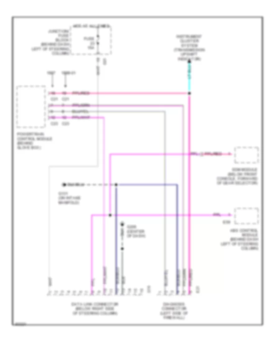
COMPUTER DATA LINES
Computer Data Lines for Suzuki Swift 1997
List of elements for Computer Data Lines for Suzuki Swift 1997:
- 1998-01
- Abs control module (behind dash left of steering column)
- C21
- C23
- Data link connector (below right side of steering column)
- Diagnosis connector (left side of firewall)
- E21
- E59
- Fuse 15a
- G01
- G131 (on intake manifold)
- G16
- G206 (center of dash)
- Hot at all times
- Instrument cluster system (transmission upshift indicator)
- Junction/ fuse block (behind dash left of steering column)
- Powertrain control module (behind glove box)
- Sdm module (below front console, forward of gear selector)
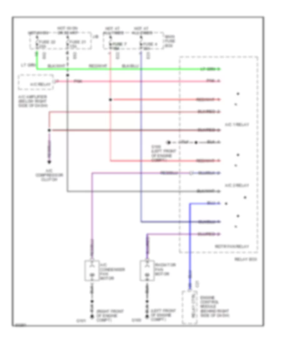
COOLING FAN
Cooling Fan Wiring Diagram for Suzuki Swift 1997
List of elements for Cooling Fan Wiring Diagram for Suzuki Swift 1997:
- (left front of engine compt)
- (right front of engine compt)
- A/c 1 relay
- A/c 2 relay
- A/c amplifier (below right side of dash)
- A/c compressor clutch
- A/c condenser fan motor
- A/c relay
- All times
- C21
- E22
- E23
- E62
- Engine control module (behind right side of dash)
- Fuse 21 15a
- Fuse 22 20a
- Fuse 4 30a
- Fuse 7 fuse 7 fuse 7 15a 15a 15a
- G100
- G100 (left front of engine compt)
- G101
- Hot at
- Hot in on
- Hot in on or start
- J/b
- Main fuse box
- Pnk
- Radiator fan motor
- Rdtr fan relay
- Relay box
- Relay ctrl
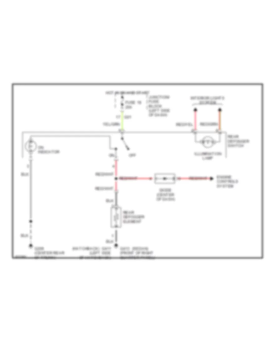
DEFOGGERS
Defogger Wiring Diagram for Suzuki Swift 1997
List of elements for Defogger Wiring Diagram for Suzuki Swift 1997:
- (hatchback)
- (sedan)
- Diode (center of dash)
- Engine controls system
- Fuse 18 20a
- G01
- G206 (center rear of trunk)
- G411 (left side of hatchback)
- G413 (front of right quarter panel)
- Hot in on and start
- Illumination lamp
- Interior lights system
- Junction/ fuse block (left side of dash)
- Off
- On indicator
- Rear defogger switch
- Rear defogger element
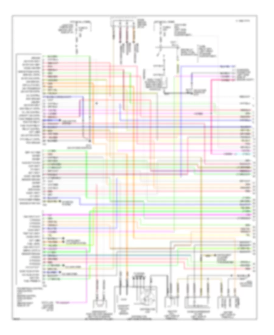
ENGINE PERFORMANCE
1.3L
1.3L, Engine Performance Wiring Diagrams (1 of 3) for Suzuki Swift 1997
List of elements for 1.3L, Engine Performance Wiring Diagrams (1 of 3) for Suzuki Swift 1997:
- (on intake manifold) g131
- 2 pos sig
- 2nd brk sol
- A/c amplifier
- A/c cut-out
- A/c idle-up sig
- Air conditioning
- C 1995 vftc
- C21
- C22
- C23
- Camshaft position (cmp) sensor
- Cooling fan system
- Crankshaft position (ckp) sensor (bottom of engine, by crankshaft pulley)
- D pos sig
- Data link coupler (left side of i/p)
- Defogger
- Diag input
- Diagnosis connector (left side side of engine compt)
- Diode (behind center of i/p)
- Dir clutch sol
- Distributor (left side of engine)
- Distributor cap
- E23
- E62
- Early fuel evaporative (efe) heater (near intake manifold)
- Ecm ground
- Ect input
- Efe on sig
- Efe relay (early fuel evaporation)
- Egr bypass cntrl
- Egr sol cntrl
- Elec idle-up sig
- Engine start sig
- Evap can cntrl
- Evap can vent
- Fuel level
- Fuel press in
- Fuel pump relay
- Fuse 23 15a
- Fuse 6 30a
- Fuse/ relay box (left front of engine compartment)
- G131 (on intake manifold)
- Ground
- Ho2s1 heater
- Ho2s1 input
- Ho2s2 heater
- Ho2s2 input
- Hot at all times
- Iat input
- Idle switch sig
- Ign coil control
- Ign pwr input
- Ign ref
- Ign trig input
- Ign trigger sig
- Igniter (left side of firewall)
- Ignition
- Ignition coil (left side of firewall)
- Inj control
- Instrument cluster system
- Instrument cluster system (tachometer)
- Interior lights
- Isc motor cntrl
- Isca relay cntrl
- Junction/ fuse block (behind left side of i/p)
- L pos sig
- Main fuse box (left side of engine compartment)
- Map input
- Memory
- Mil ind control
- N pos sig
- Nca
- Noise suppressor filter (left side of firewall)
- Not used
- P pos sig
- Pcm ground
- Pnk
- Powertrain control module (pcm) (a/t) engine control module (ecm) (m/t) (behind right side of i/p)
- Ptc relay cntrl
- Pwr steer press
- R pos sig
- Rad fan relay
- Red
- Ref voltage
- Relay control
- Sensor ground
- Serial data in
- Starting system
- System
- Tank press cntrl
- Test sw input
- To spark plugs
- Tp input
- Upshift ind cntrl
- Vss input (a/t)
- Vss input (m/t)
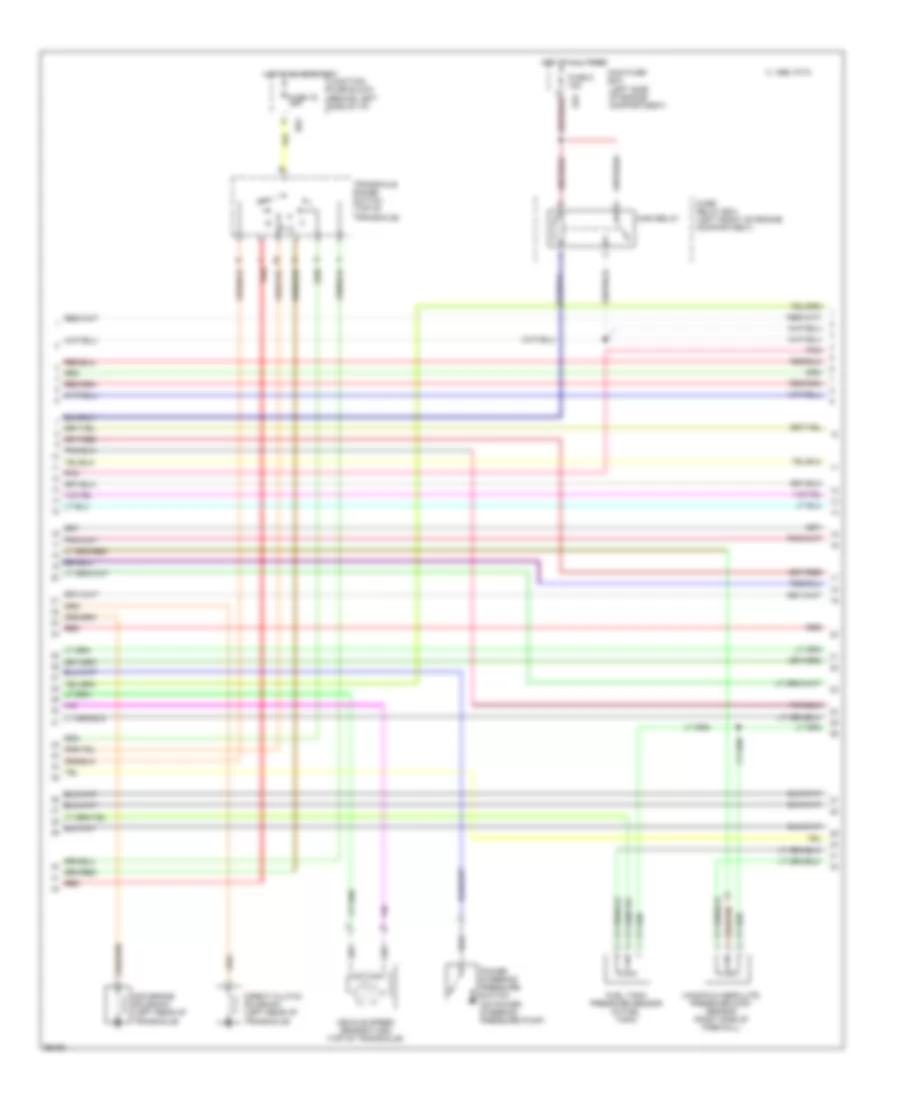
1.3L, Engine Performance Wiring Diagrams (2 of 3) for Suzuki Swift 1997
List of elements for 1.3L, Engine Performance Wiring Diagrams (2 of 3) for Suzuki Swift 1997:
- (left side of engine compartment)
- 2nd brake solenoid (left rear of transaxle)
- C 1995 vftc
- Direct clutch solenoid (left rear of transaxle)
- E23
- E63
- Fuel tank pressure sensor (in fuel tank)
- Fuse 16 15a
- Fuse 5 15a
- Fuse/ relay box (left front of engine compartment)
- Hot at all times
- Hot in on or start
- Junction/ fuse block (behind left side of i/p)
- Main fuse box
- Main relay
- Manifold absolute pressure (map) sensor (right side of firewall)
- N d
- Pnk
- Power steering pressure switch (on power steering pressure pump)
- Red
- Transaxle range switch (top of transaxle)
- Vehicle speed sensor (vss) (top of transaxle)
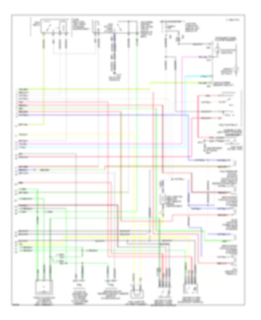
1.3L, Engine Performance Wiring Diagrams (3 of 3) for Suzuki Swift 1997
List of elements for 1.3L, Engine Performance Wiring Diagrams (3 of 3) for Suzuki Swift 1997:
- (a/t)
- (center rear of trunk) g407
- (m/t)
- (on intake manifold)
- (rear of intake manifold)
- 1995 vftc c
- Ccv (center of firewall)
- Compartment)
- E62
- Egr solenoid vacauum valve 2 (top rear of engine)
- Egr solenoid vacuum valve 1 (top rear of engine)
- Engine coolant temperature (ect) sensor
- Evap canister purge valve (top rear of engine)
- Fuel injector (in throttle body)
- Fuel injector resistor (left rear of engine compartment)
- Fuel pump (in fuel tank)
- Fuel pump relay
- Fuse 21 15a
- Fuse/ relay box (left front of engine compartment)
- Fuse/relay box (left front of engine
- G01
- G08
- G131
- G15
- Heated oxygen sensor 1 (ho2s) (on exhaust manifold)
- Heated oxygen sensor 2 (ho2s) (on exhaust manifold)
- Hot in on or start
- Idle speed control (isc) motor (top of engine, on throttle body)
- Idle switch open at idle
- Instrument panel cluster assembly
- Intake air temperature (iat) sensor (attached to air cleaner assembly)
- Isca
- Junction/ fuse block (behind left side of i/p)
- Malfunction indicator
- Nca
- Pnk
- Red
- Relay
- S313
- Tank pressure control solenoid vacuum valve (right rear of engine compartment)
- Throttle position (tp) sensor (on throttle body assembly)
- Upshift indicator (m/t only)
- Vehicle speed sensor (vss) (m/t)
EXTERIOR LIGHTS
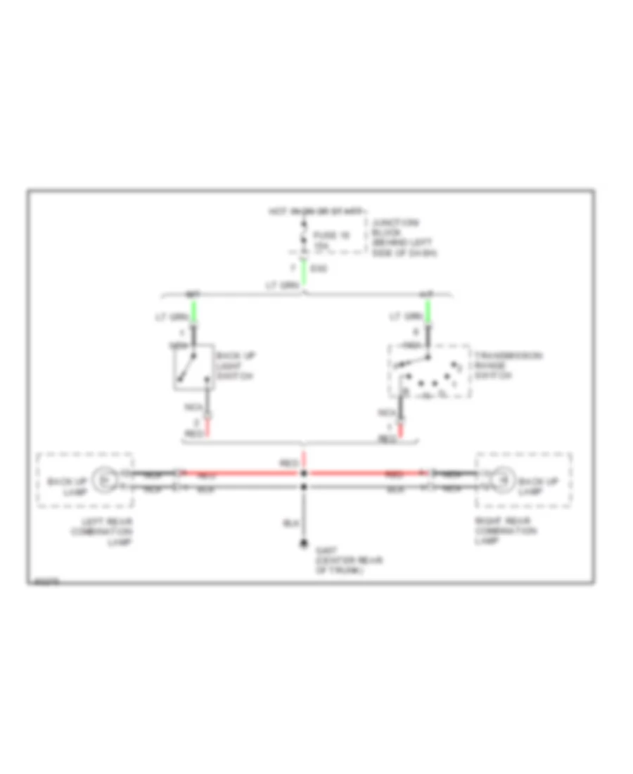
Back-up Lamps Wiring Diagram for Suzuki Swift 1997
List of elements for Back-up Lamps Wiring Diagram for Suzuki Swift 1997:
- A/t
- Back up lamp
- Back up light switch
- E62
- Fuse 16 15a
- G407 (center rear of trunk)
- Hot in on or start
- Junction/ block (behind left side of dash)
- Left rear combination lamp
- M/t
- Nca
- Red
- Right rear combination lamp
- Transmission range switch
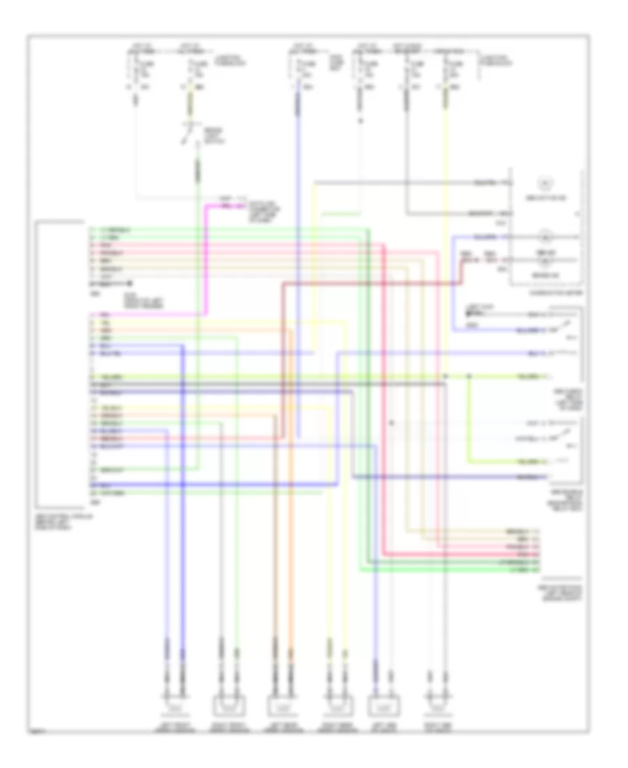
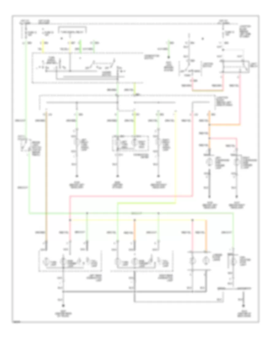
Exterior Lamps Wiring Diagram for Suzuki Swift 1997
List of elements for Exterior Lamps Wiring Diagram for Suzuki Swift 1997:
- (a/t) 3 (m/t) 2
- Anti- lock brakes system
- Brake light switch (top of brake pedal)
- Combination meter
- Combination switch
- E60
- E62
- E63
- E64
- E67
- Fuse 12 15a
- Fuse 15 15a
- Fuse 16 15a
- G01
- G08
- G106 (behind left headlamp)
- G107 (behind right headlamp)
- G14
- G206 (center of dash)
- G407 (center rear of trunk)
- G412 (center of back door)
- Hatchback
- Hazard switch
- Head
- High mounted stop light
- Hot at all times
- Hot in on or start
- Junction/ block (behind left side of dash)
- L02
- Left clearance/ side marker lamp
- Left front turn signal lamp
- Left rear combination lamp
- Left turn indic
- License plate lamps
- Light relay
- Lighting switch
- Nca
- Off
- Park
- Right clearance/ side marker lamp
- Right front turn signal lamp
- Right rear combination lamp
- Right turn indic
- Sedan
- Side marker lamp
- Tail/ stop lamp
- Turn lamp
- Turn signal relay
- Turn signal switch
GROUND DISTRIBUTION
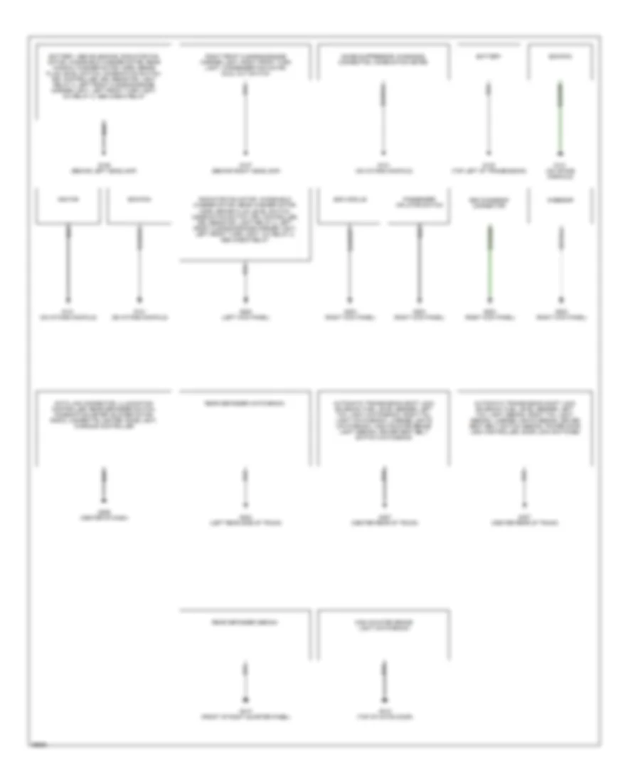
Ground Distribution Wiring Diagram for Suzuki Swift 1997
List of elements for Ground Distribution Wiring Diagram for Suzuki Swift 1997:
- Automatic transmission shift lock solenoid, fuel level sender, left tail light (hatchback), right tail light (hatchback), license lights (hatchback), high mounted brake light (sedan), driver seat belt switch (hatchback)
- Automatic transmission shift lock solenoid, fuel level sender, left tail light (sedan), right tail light (sedan), license lights (sedan), driver seat belt switch (sedan), power door lock controller, door lock switches
- Battery
- Battery, abs solenoids, radiator fan motor, windshield washer motor, rear window washer motor, horn, brake fluid level switch, combination switch, drl controller, drl resistor, light relay 2, left front clearance/side marker light, left front turn light, a/c relay 2, abs check relay
- Data link connector, illumination controller, rear defogger switch, combination meter, blower motor, radio, cigarette lighter, dome light, warning controller
- Ecm/pcm
- G-sensor
- G106 (behind left headlamp)
- G107 (behind right headlamp)
- G130 (top left of transmission)
- G131 (on intake manifold)
- G200 (left kick panel)
- G203 (right kick panel)
- G206 (center of dash)
- G404 (left rear side of trunk)
- G407 (center rear of trunk)
- G412 (top of hatch door)
- G413 (front of right quarter panel)
- High mounted brake light (hatchback)
- Ignitor
- Noise suppressor, diagnosis connector, combination meter
- Passenger inflator switch
- Radiator fan motor, windshield washer motor, rear washer motor, horn, brake fluid level switch, combination switch, drl controller, drl resistor, light relay 2, left front clearance/side marker light, left front turn light, a/c relay 2, abs check relay
- Rear defogger (hatchback)
- Rear defogger (sedan)
- Right front clearance/side marker light, right front turn light, condenser fan motor, dual cut switch
- Sdm diagnosis connector
- Sdm module
HEADLIGHTS
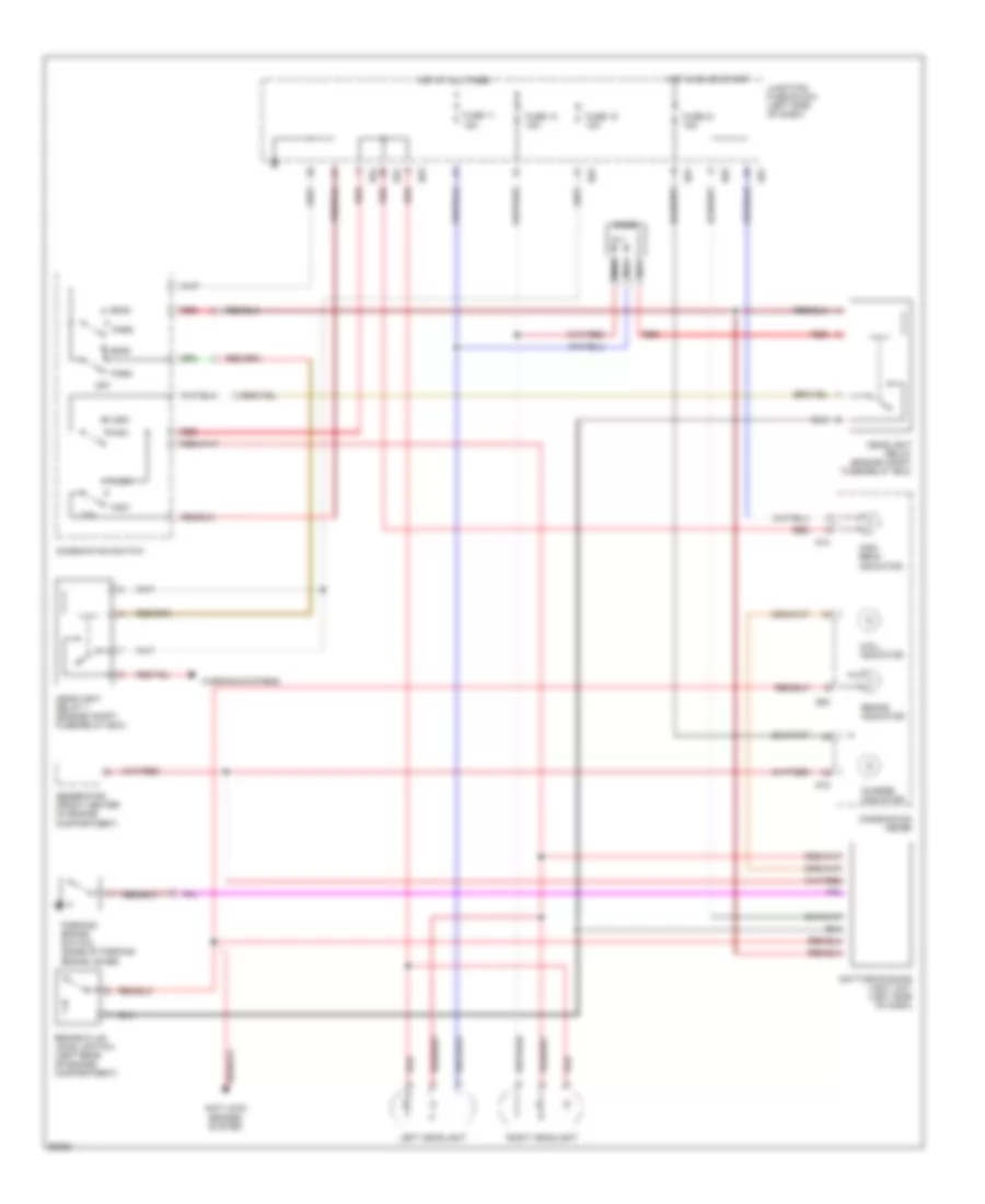
Headlight Wiring Diagram for Suzuki Swift 1997
List of elements for Headlight Wiring Diagram for Suzuki Swift 1997:
- Anti-lock brakes system
- Brake fluid level switch (left rear of engine compartment)
- Brake indicator
- Charge indicator
- Combination meter
- Combination switch
- D.r.l. indicator
- Daytime running light unit (left side of dash)
- Diode
- E62
- E63
- E64
- Flash
- Fuse 11 15a
- Fuse 13 15a
- Fuse 15 15a
- Fuse 21 15a
- G01
- G08
- G14
- G15
- Generator (front center of engine compartment)
- Head
- Headlight relay (engine compt fuse/relay box)
- Headlight relay 1 (engine compt fuse/relay box)
- High
- High beam indicator
- Hot at all times
- Hot in on or start
- Junction/ fuse block (left side of dash)
- Left headlight
- Low
- Nca
- Off
- Park
- Parking brake switch (base of parking brake lever)
- Red
- Right headlight
- Warning systems
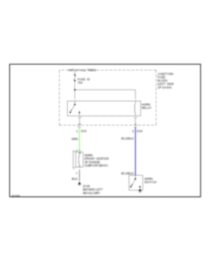
HORN
Horn Wiring Diagram for Suzuki Swift 1997
List of elements for Horn Wiring Diagram for Suzuki Swift 1997:
- E63
- E64
- Fuse 19 15a
- G106 (behind left headlamp)
- Horn (front center of engine compartment)
- Horn relay
- Horn switch
- Hot at all times
- Junction/ fuse block (left side of dash)
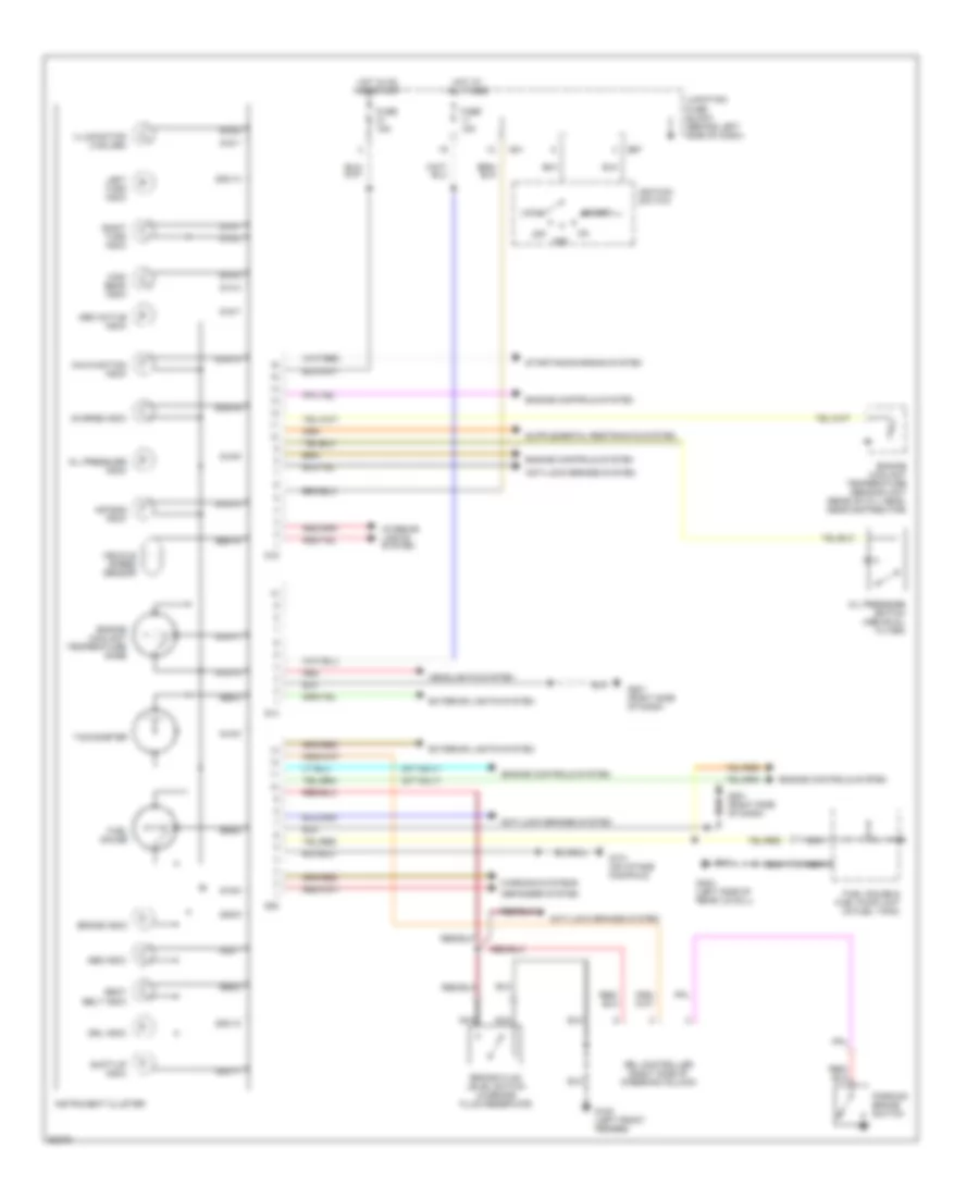
INSTRUMENT CLUSTER
Instrument Cluster Wiring Diagram for Suzuki Swift 1997
List of elements for Instrument Cluster Wiring Diagram for Suzuki Swift 1997:
- (m/t only)
- Abs active indic
- Abs indic
- Acc
- Air bag indic
- Anti-lock brakes system
- Brake fluid level switch (in brake fluid reservoir)
- Brake indic
- Charge indic
- Defogger system
- Drl controller (right side of steering column)
- Drl indic
- E67
- Engine controls system
- Engine coolant temperature gage
- Engine coolant temperature sending unit (rear of cyl head, near distributor)
- Exterior lights system
- Fuel gauge
- Fuel gauge & fuel pump unit (in fuel tank)
- Fuse 15a
- G01
- G08
- G08-10
- G08-11
- G08-12
- G08-13
- G08-2
- G08-4
- G08-5
- G08-7
- G08-9
- G100 (left front fender)
- G131 (on intake manifold)
- G14
- G14-1
- G14-2
- G14-3
- G14-4
- G15
- G15-1
- G15-10
- G15-11
- G15-13
- G15-15
- G15-16
- G15-2
- G15-5
- G15-7
- G15-8
- G15-9
- G201 (right side of dash)
- G404 (left side of rear lid sill)
- Headlights system
- High beam indic
- Hot at all times
- Hot in on and start
- Ignition switch
- Illumination (3 bulbs)
- Instrument cluster
- Interior lights system
- Junction/ fuse block (behind left side of dash)
- Left turn indic
- Lock
- Malfunction indic
- Nca
- Off
- Oil pressure indic
- Oil pressure switch (above oil filter)
- Parking brake switch
- Red
- Right turn indic
- Seat belt indic
- Shift-up indic
- Start
- Starting/charging system
- Tachometer
- Vehicle speed sensor
- Warning systems
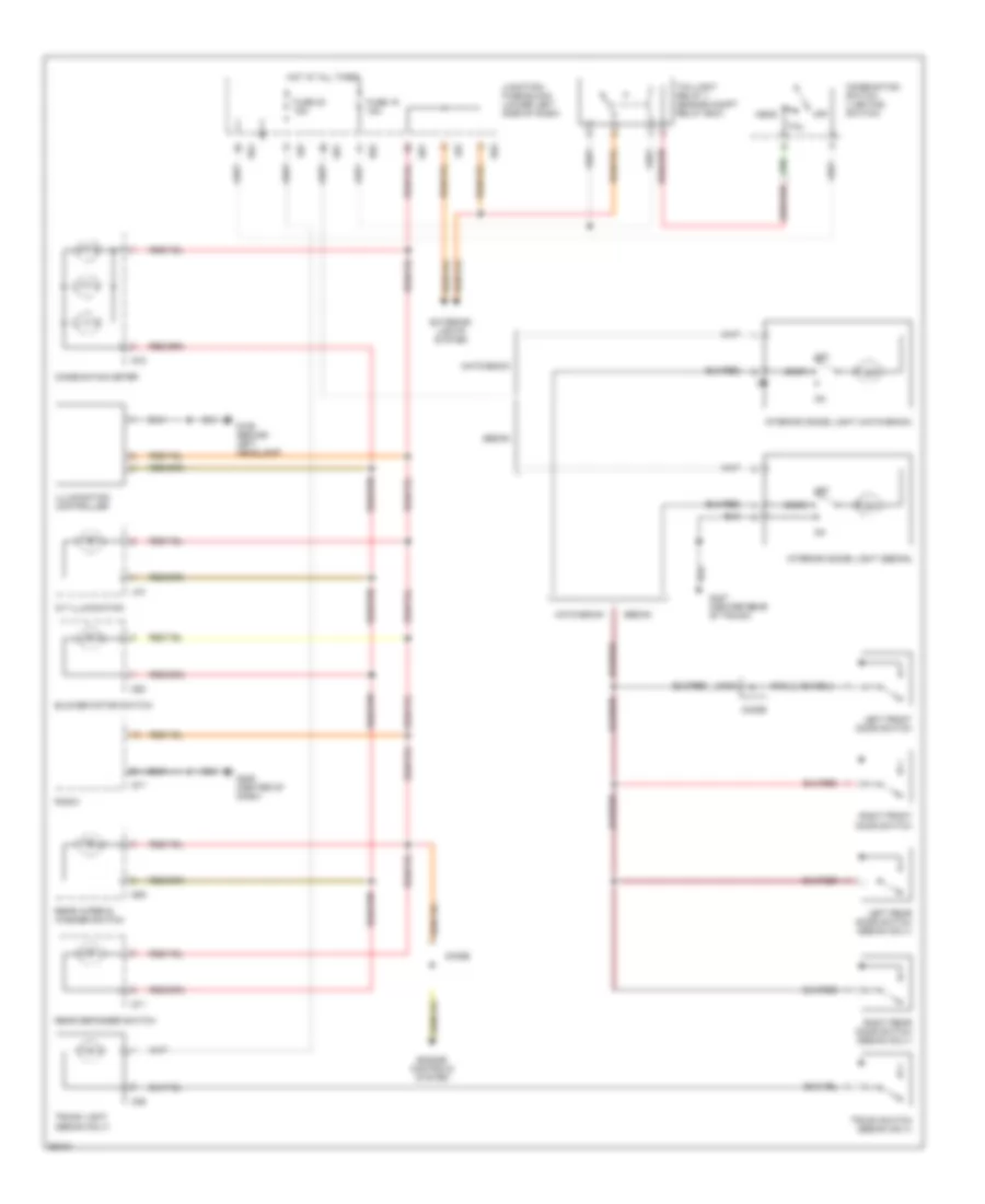
INTERIOR LIGHTS
Interior Light Wiring Diagram for Suzuki Swift 1997
List of elements for Interior Light Wiring Diagram for Suzuki Swift 1997:
- A/t illumination
- Blower motor switch
- Combination meter
- Combination switch (lighting switch)
- Diode
- Door
- E62
- E63
- E64
- Engine controls system
- Exterior lights system
- Fuse 15 15a
- Fuse 23 15a
- G01
- G09
- G106 (behind left headlamp)
- G11
- G15
- G17
- G20
- G206 (center of dash)
- G407 (center rear of trunk)
- Hatchback
- Head
- Hot at all times
- Illumination controller
- Interior (dome) light (hatchback)
- Interior (dome) light (sedan)
- Junction/ fuse block (lower left side of dash)
- L02
- L04
- Left front door switch
- Left rear door switch (sedan only)
- Nca
- O06
- Off
- Radio
- Rear defogger switch
- Rear wiper & washer switch
- Right front door switch
- Right rear door switch (sedan only)
- Sedan
- Tail
- Taillight relay 1 (engine compt relay box)
- Trunk light (sedan only)
- Trunk switch (sedan only)
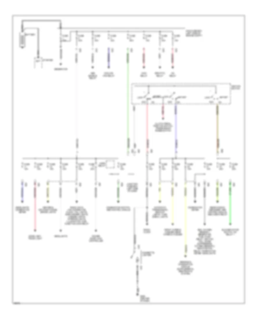
POWER DISTRIBUTION
Power Distribution Wiring Diagram for Suzuki Swift 1997
List of elements for Power Distribution Wiring Diagram for Suzuki Swift 1997:
- A/c relay
- Abs enable relay
- Acc
- Automatic transmission, back-up lights, turn signal lights
- Bat
- Battery
- Blower motor switch, a/c relay 1
- Cigarette lighter
- Clutch pedal position switch, transmission range switch
- Combination meter
- Combination switch, abs control module
- Cooling fan relay
- Dome light, trunk light
- E22
- E23
- E24
- E25
- E61
- E62
- E63
- E66
- E67
- Ecm, oxygen sensor 1, generator, fuel pump relay, ignition coil, noise suppressor, oxygen sensor 2, radiator fan relay, combination meter, headlights
- Efe (ptc) relay
- Front wiper & washer, rear wiper & washer
- Fuse 15a
- Fuse 20a
- Fuse 30a
- Fuse 40a
- Fuse 60a
- Fuse 70a
- G01
- G19
- G206 (center of dash)
- Generator
- Headlights
- Headlights, combination meter
- Heater & air conditioning, brake lights
- Horn relay
- Ignition switch
- Junction/ fuse box (left side of dash)
- L02
- Lock
- Main fuse box (left side of engine compt)
- Main relay
- Power door lock controller
- Radio, clock
- Radio, data link connector, clock, tail lights, side marker lights, license lights, interior lights, illumination, fuel injection main relay
- Rear window defogger, abs control module, abs check relay
- Start
- Starter
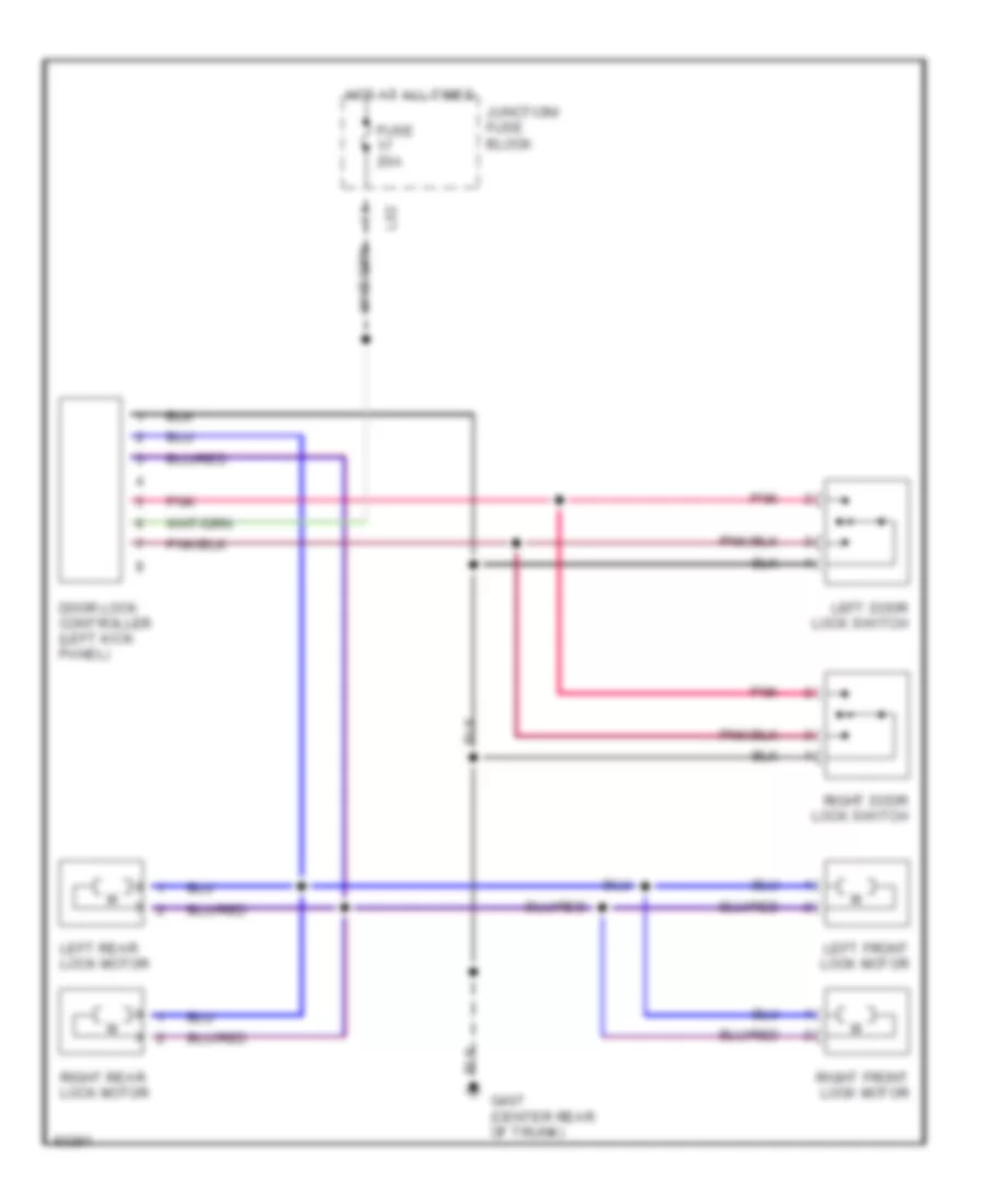
POWER DOOR LOCKS
Power Door Lock Wiring Diagram for Suzuki Swift 1997
List of elements for Power Door Lock Wiring Diagram for Suzuki Swift 1997:
- Door lock controller (left kick panel)
- Fuse 20a
- G407 (center rear of trunk)
- Hot at all times
- Junction/ fuse block
- L02
- Left door lock switch
- Left front lock motor
- Left rear lock motor
- Pnk
- Right door lock switch
- Right front lock motor
- Right rear lock motor
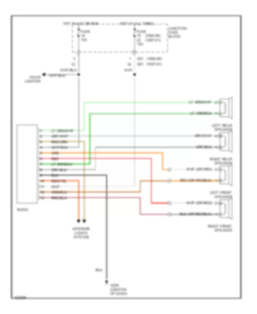
RADIO
Radio Wiring Diagrams for Suzuki Swift 1997
List of elements for Radio Wiring Diagrams for Suzuki Swift 1997:
- (1994-96)
- (1994-96) (1997-01)
- (1997-01)
- Cigar lighter
- Fuse 15a
- G01
- G206 (center of dash)
- Hot at all times
- Hot in acc or run
- Interior lights system
- Junction fuse block
- Left front speaker
- Left rear speaker
- Radio
- Red
- Right front speaker
- Right rear speaker
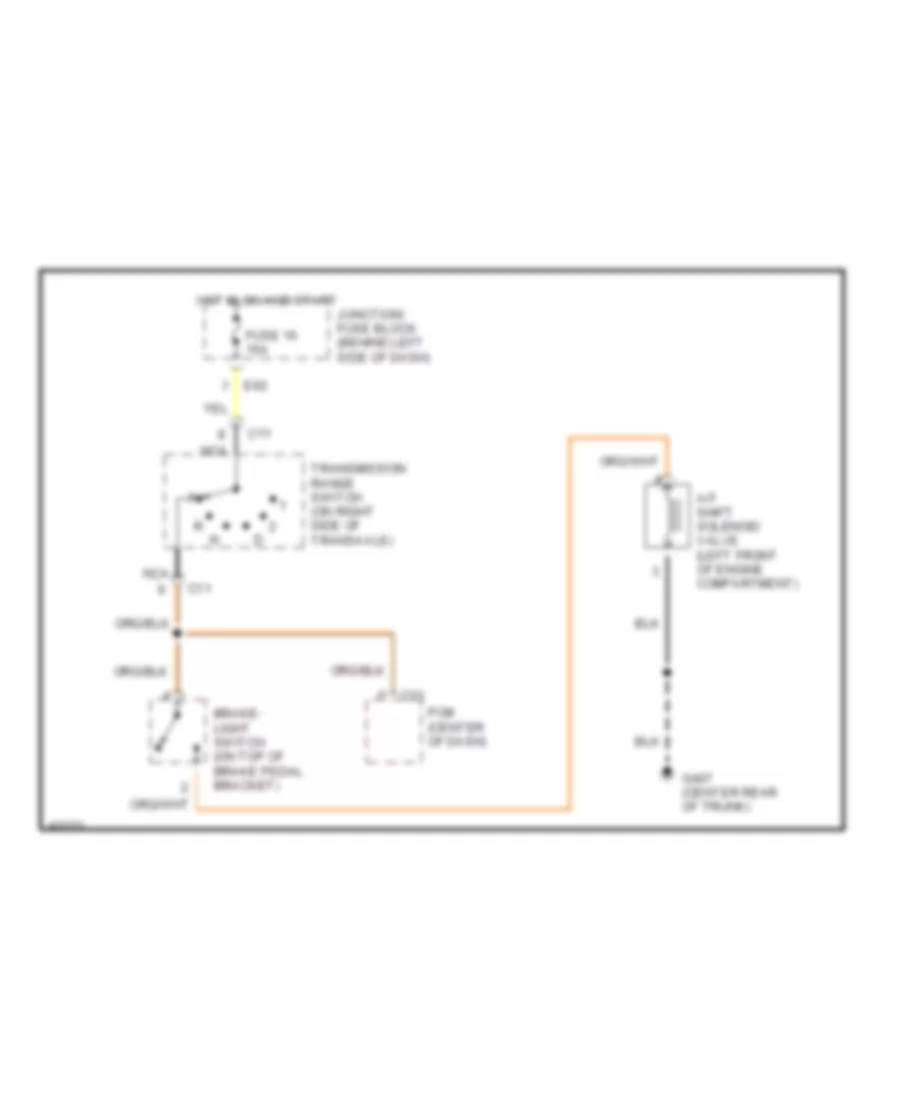
SHIFT INTERLOCKS
Shift Interlock Wiring Diagram for Suzuki Swift 1997
List of elements for Shift Interlock Wiring Diagram for Suzuki Swift 1997:
- A/t shift solenoid valve (left front of engine compartment)
- Brake- light switch (on top of brake pedal bracket)
- C11
- C23
- E62
- Fuse 16 15a
- G407 (center rear
- Hot in on and start
- Junction/ fuse block (behind left side of dash)
- Nca
- Of trunk)
- Pcm (center of dash)
- Transmission range switch (on right side of transaxle)
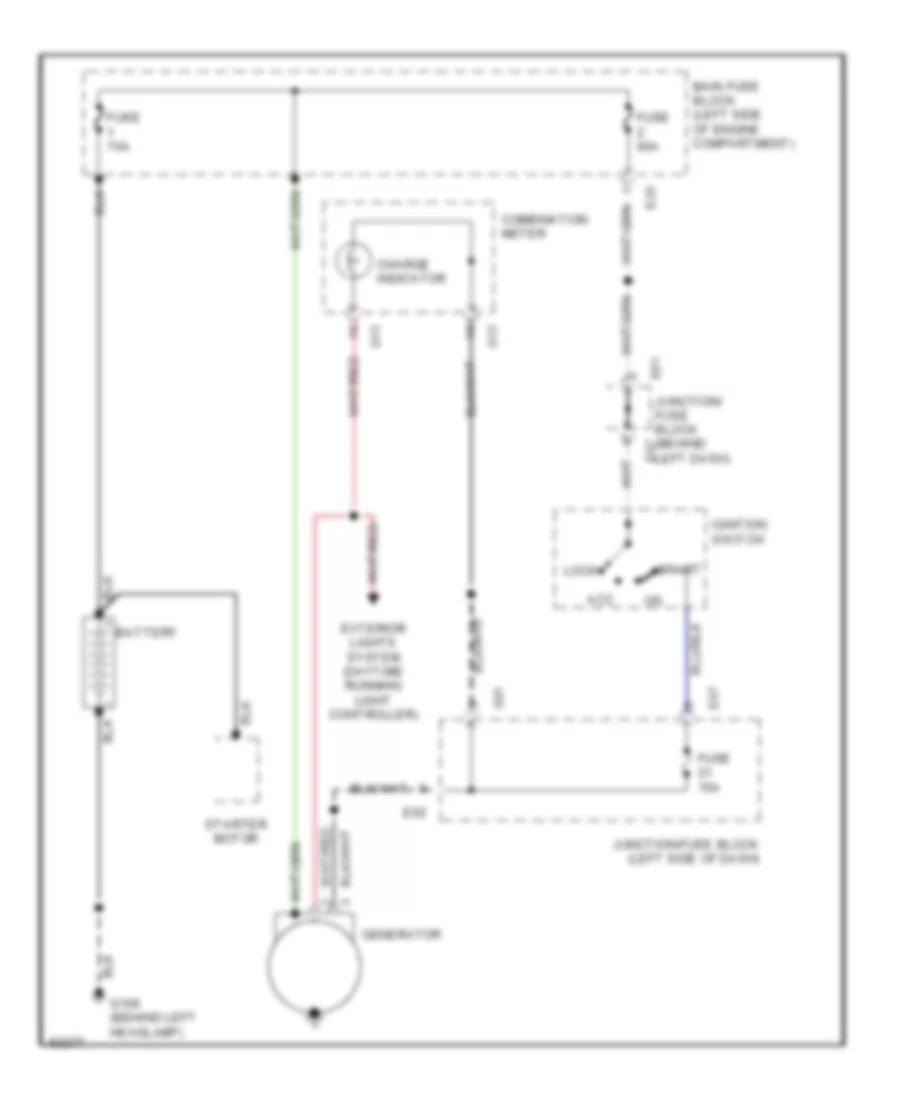
STARTING/CHARGING
Charging Wiring Diagram for Suzuki Swift 1997
List of elements for Charging Wiring Diagram for Suzuki Swift 1997:
- Acc
- Battery
- Charge indicator
- Combination meter
- E25
- E61 junction/ fuse block (behind left dash)
- E62
- E67
- Exterior lights system (daytime running light controller)
- Fuse 15a
- Fuse 60a
- Fuse 70a
- G01
- G106 (behind left headlamp)
- G15
- Generator
- Ignition switch
- Junction/fuse block (left side of dash)
- Lock
- Main fuse block (left side of engine compartment)
- Start
- Starter motor
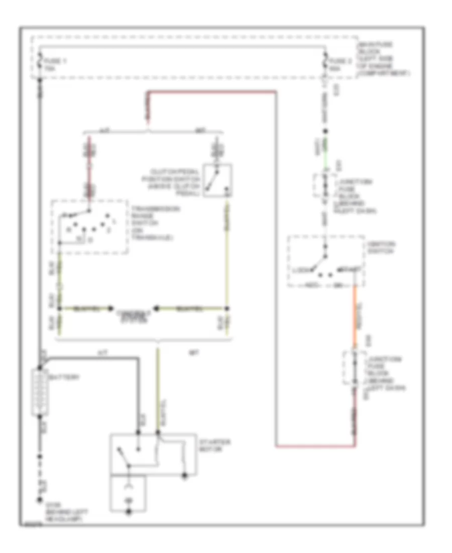
Starting Wiring Diagram for Suzuki Swift 1997
List of elements for Starting Wiring Diagram for Suzuki Swift 1997:
- A/t
- Acc
- Battery
- Clutch pedal position switch (above clutch pedal)
- Controls engine system
- E25
- E61 junction/ fuse block (behind left dash)
- E62
- E66
- E67
- Fuse 1 70a
- Fuse 2 60a
- G106 (behind left headlamp)
- Ignition switch
- Junction/ fuse block (behind left dash)
- Lock
- M/t
- Main fuse block (left side of engine compartment)
- Red
- Start
- Starter motor
- Transmission range switch (on transaxle)
SUPPLEMENTAL RESTRAINTS
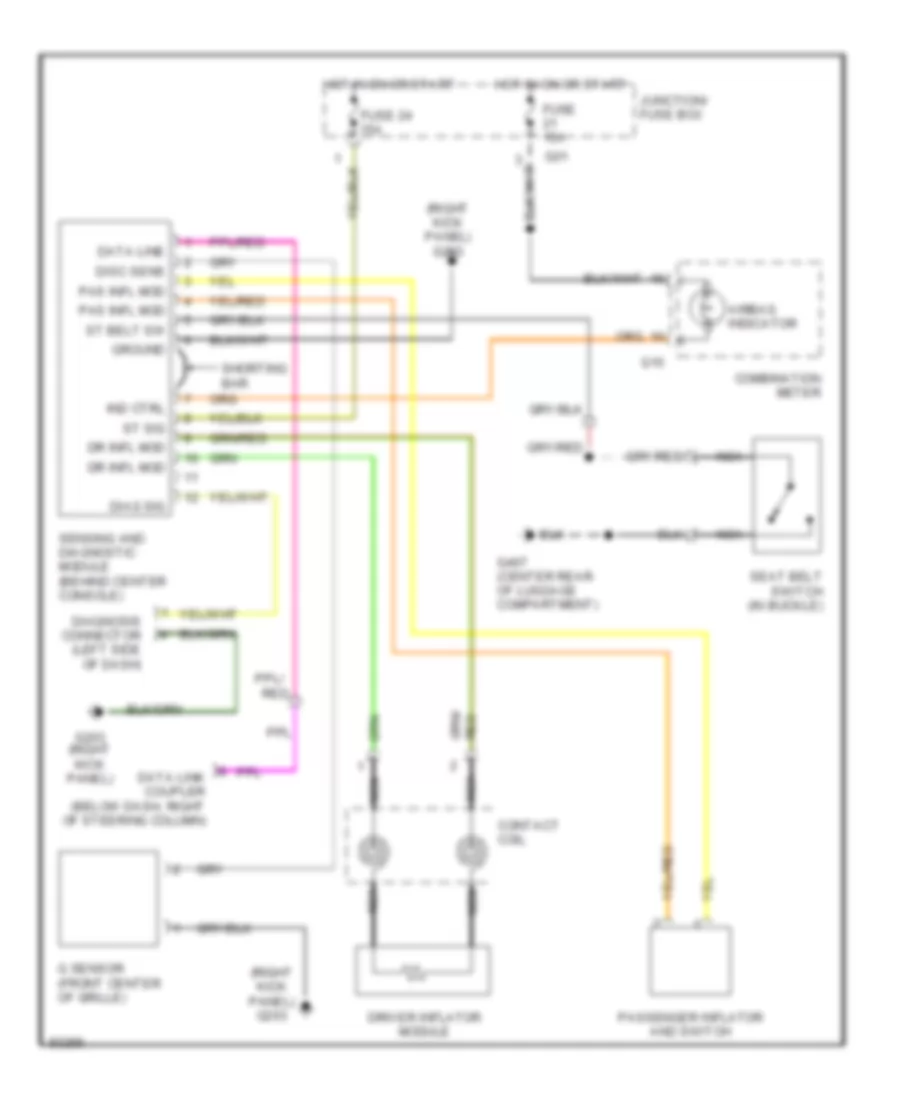
Supplemental Restraint Wiring Diagram for Suzuki Swift 1997
List of elements for Supplemental Restraint Wiring Diagram for Suzuki Swift 1997:
- (right kick panel) g203
- Airbag indicator
- Combination meter
- Contact coil
- Data line
- Data link coupler (below dash, right of steering column)
- Diag sig
- Diagnosis connector (left side of dash)
- Disc sens
- Dr infl mod
- Driver inflator module
- Fuse 15a
- Fuse 24 15a
- G sensor (front center of grille)
- G01
- G15
- G203 (right kick panel)
- G407 (center rear of luggage compartment)
- Ground
- Hot in on or start
- Ind ctrl
- Junction/ fuse box
- Nca
- Pas infl mod
- Passenger inflator and switch
- Red
- Seat belt switch (in buckle)
- Sensing and diagnostic module (behind center console)
- Shorting bar
- St belt sw
- St sig
TRANSMISSION
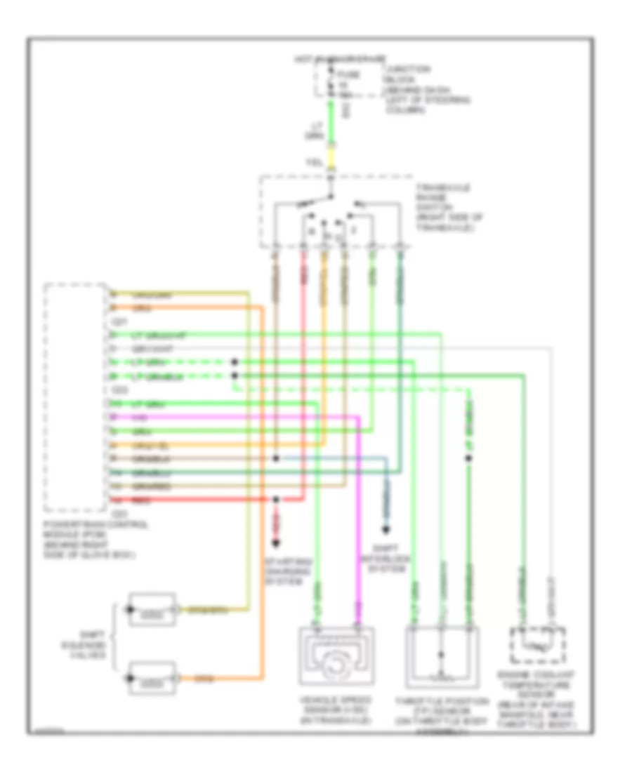
A/T Wiring Diagram for Suzuki Swift 1997
List of elements for A/T Wiring Diagram for Suzuki Swift 1997:
- C21
- C22
- C23
- E62
- Engine coolant temperature sensor (rear of intake manifold, near throttle body)
- Fuse 15a
- Hot in on or start
- Junction block (behind dash, left of steering column)
- N d
- Powertrain control module (pcm) (behind right side of glove box)
- Red
- Shift interlock system
- Shift solenoid valves
- Starting/ charging system
- Throttle position (tp) sensor (on throttle body assembly)
- Transaxle range switch (right side of transaxle)
- Vehicle speed sensor (vss) (in transaxle)
WARNING SYSTEMS
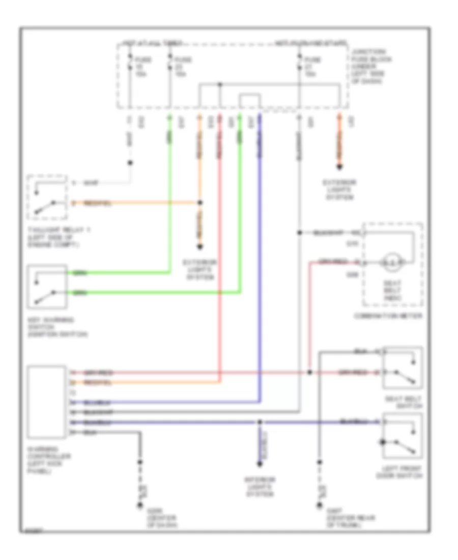
Warning System Wiring Diagrams for Suzuki Swift 1997
List of elements for Warning System Wiring Diagrams for Suzuki Swift 1997:
- Combination meter
- E62
- E63
- E67
- Exterior lights system
- Fuse 15a
- G01
- G08
- G15
- G206 (center of dash)
- G407 (center rear of trunk)
- Hot at all times
- Hot in on and start
- Interior lights system
- Junction/ fuse block (under left side of dash)
- Key warning switch (ignition switch)
- L02
- Left front door switch
- Seat belt indic
- Seat belt switch
- Taillight relay 1 (left side of engine compt)
- Warning controller (left kick panel)
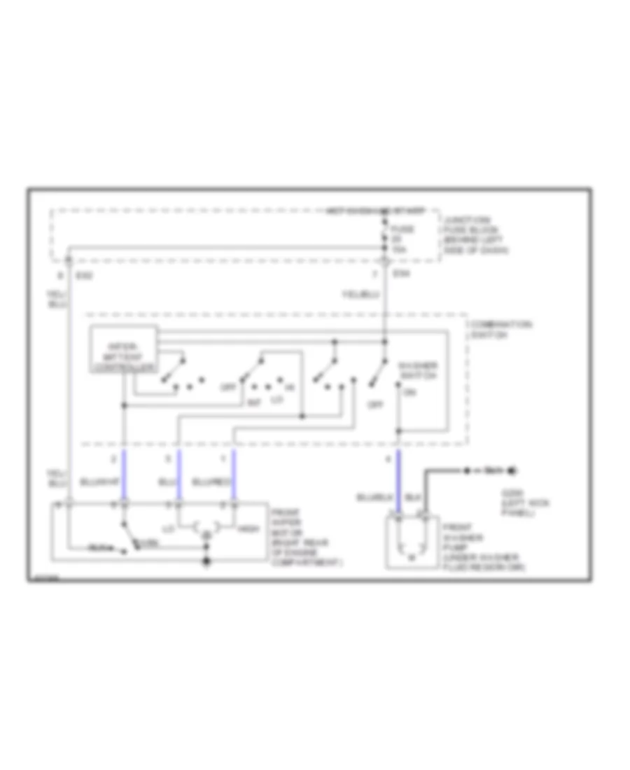
WIPER/WASHER
Front Wiper/Washer Wiring Diagram for Suzuki Swift 1997
List of elements for Front Wiper/Washer Wiring Diagram for Suzuki Swift 1997:
- Combination switch
- E62
- E64
- Front washer pump (under washer fluid reservoir)
- Front wiper motor (right rear of engine compartment)
- Fuse 15a
- G200 (left kick panel)
- High
- Hot in on and start
- Inter- mittent controller
- Junction/ fuse block (behind left side of dash)
- Lo int
- Off
- Park
- Run
- Washer switch
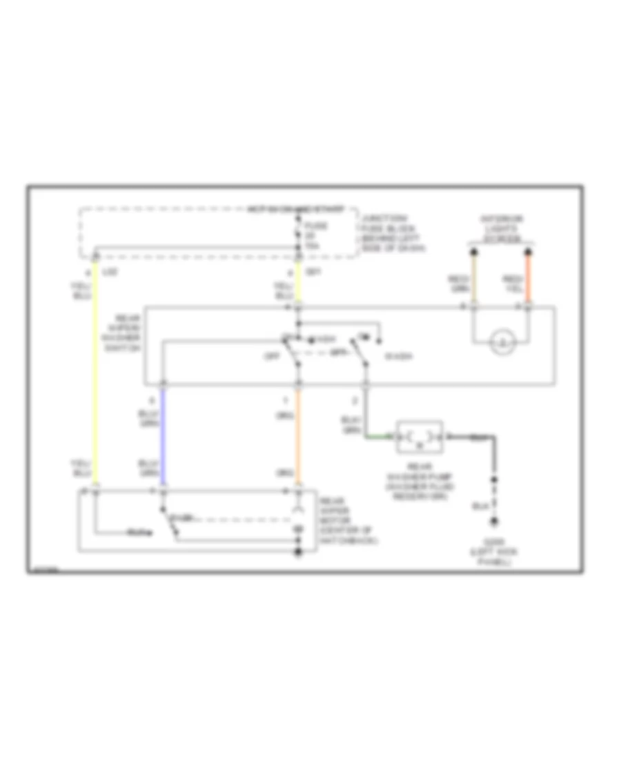
Rear Wiper/Washer Wiring Diagram for Suzuki Swift 1997
List of elements for Rear Wiper/Washer Wiring Diagram for Suzuki Swift 1997:
- Fuse 15a
- G01
- G200 (left kick panel)
- Hot in on and start
- Interior lights system
- Junction/ fuse block (behind left side of dash)
- L02
- Off
- Park
- Rear washer pump (washer fluid reservoir)
- Rear wiper motor (center of hatchback)
- Rear wiper/ washer switch
- Run
- Wash

 Čeština
 Dansk
Dansk Deutsch
 Ελληνικά
 English
 English
 Español
 Suomi
Suomi Français
 Français
 עברית
עברית Hrvatski
 Magyar
 Italiano
 日本語
日本語 한국어
한국어 Nederlands
 Polski
 Português
 Português
 Română
 Slovenčina
 Slovenščina
 Svenska
 Türkçe
 中文 (中国)