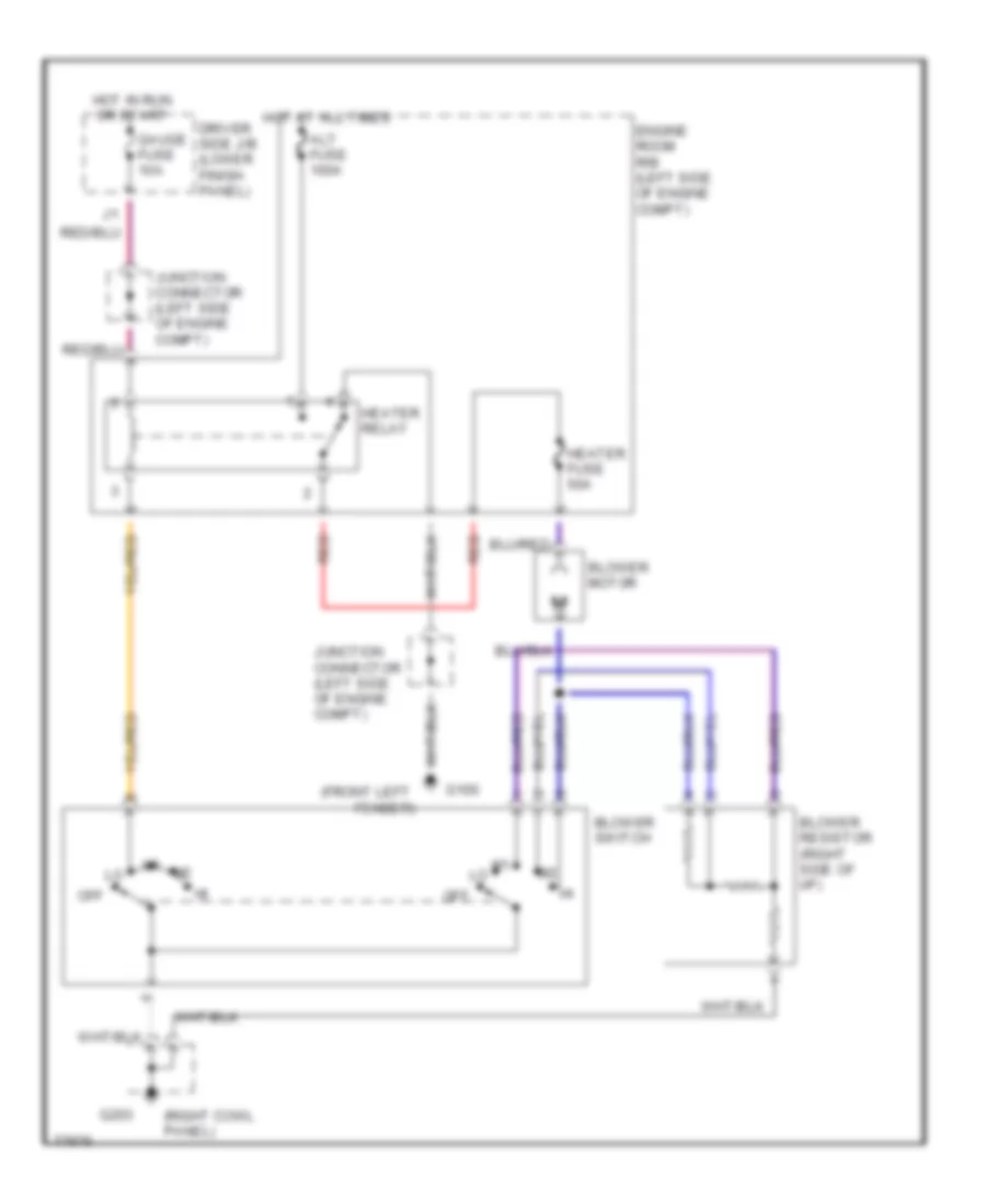
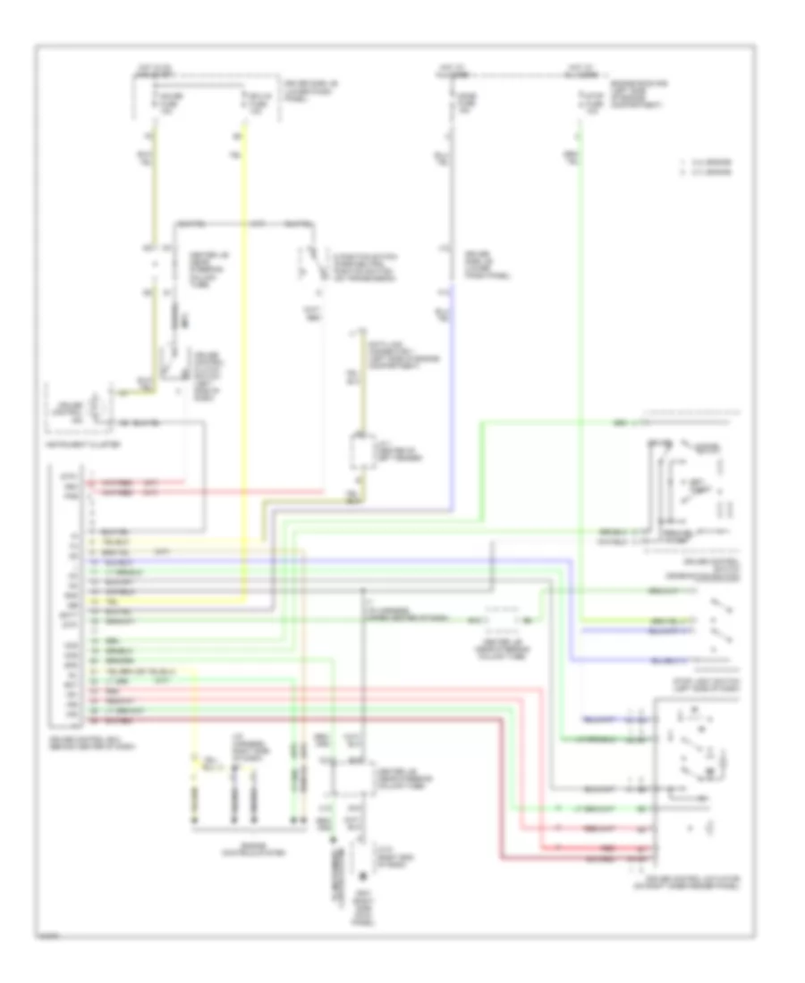
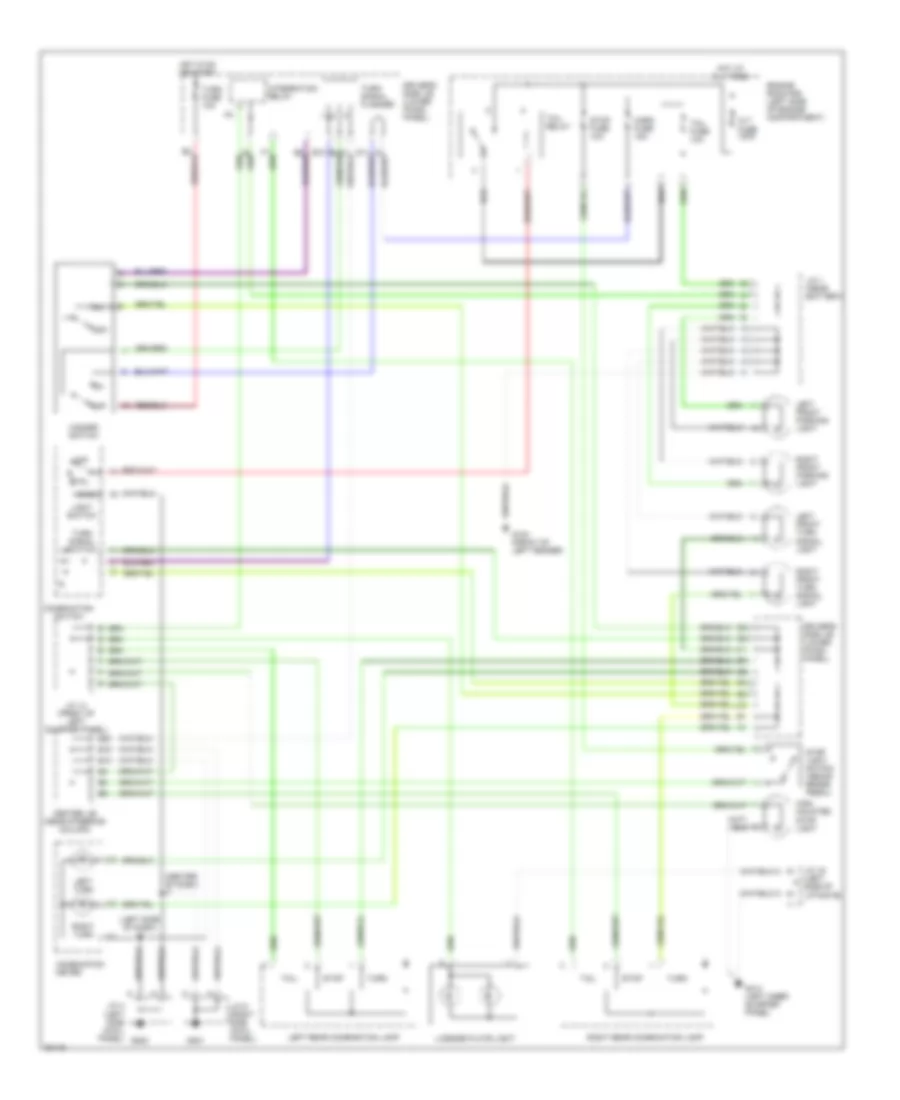
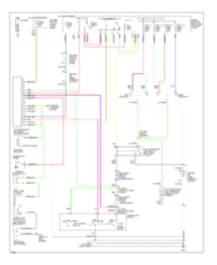
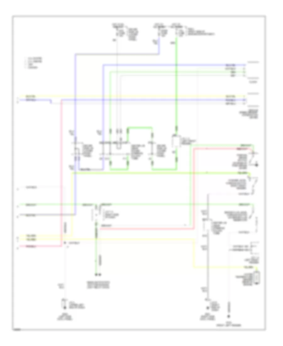
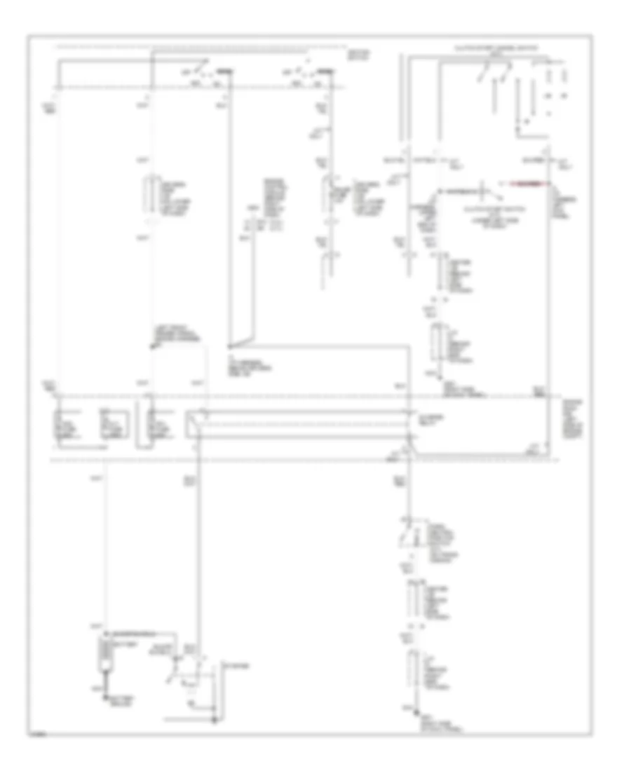
AIR CONDITIONING
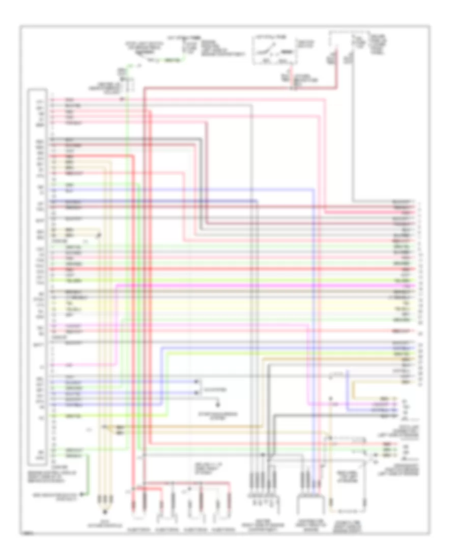
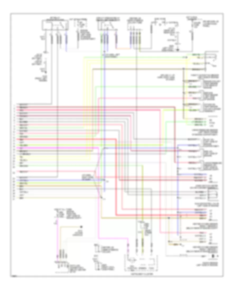
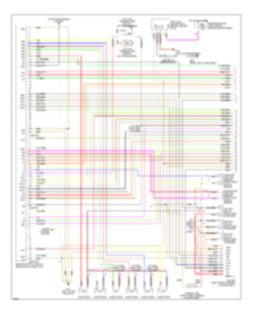
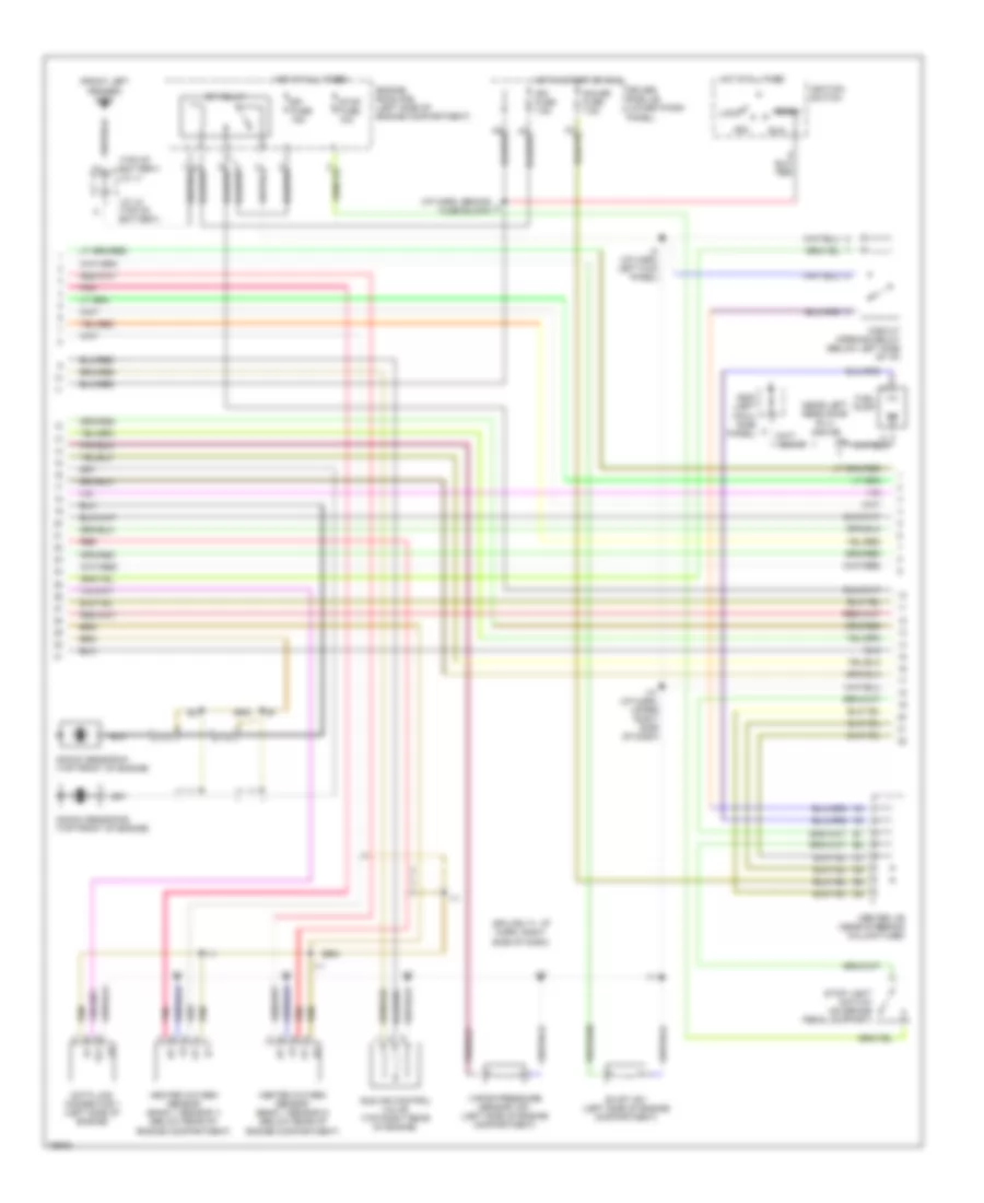
A/C Wiring Diagram for Toyota 4Runner Limited 1996
 https://portal-diagnostov.com/license.html
Automotive Electricians Portal FZCO
Automotive Electricians Portal FZCO
https://portal-diagnostov.com/license.html
https://portal-diagnostov.com/license.html
Automotive Electricians Portal FZCO
Automotive Electricians Portal FZCO
List of elements for A/C Wiring Diagram for Toyota 4Runner Limited 1996:
- (right cowl panel)
- 2.7l a/t
- 2.7l m/t
- 3.4l a/t
- 3.4l m/t
- A/c
- A/c amplifier (right side of i/p)
- A/c dual pres- sure switch (right front of engine compt)
- A/c fuse 10a
- A/c magnetic clutch
- A/c switch
- A/c thermistor (right side of i/p)
- Ac1
- Act
- Alt fuse 100a
- B/v
- Blower motor
- Blower resistor (right side of i/p)
- Blower switch
- Center j/b (near steering column)
- D10
- D11
- D12
- Defroster
- Driver side j/b (lower finish panel)
- Engine control module (right side of i/p)
- Engine room r/b (left side of engine compt)
- G100 (front left fender)
- G203
- G203 (right cowl panel)
- Gauge fuse 10a
- Gnd
- H20
- Heater fuse 50a
- Heater relay
- Hot at all times
- Hot in run or start
- Integration relay
- Junction connector (left side of engine compt)
- Mgc
- Mode switch
- Off
- Pnk
- Prs
- Rear heater blower motor
- Rear heater blower resistor (below center console)
- Rear heater blower switch
- Rear heater relay (below center console)
- Red
- Rr htr fuse 10a
- Solid state
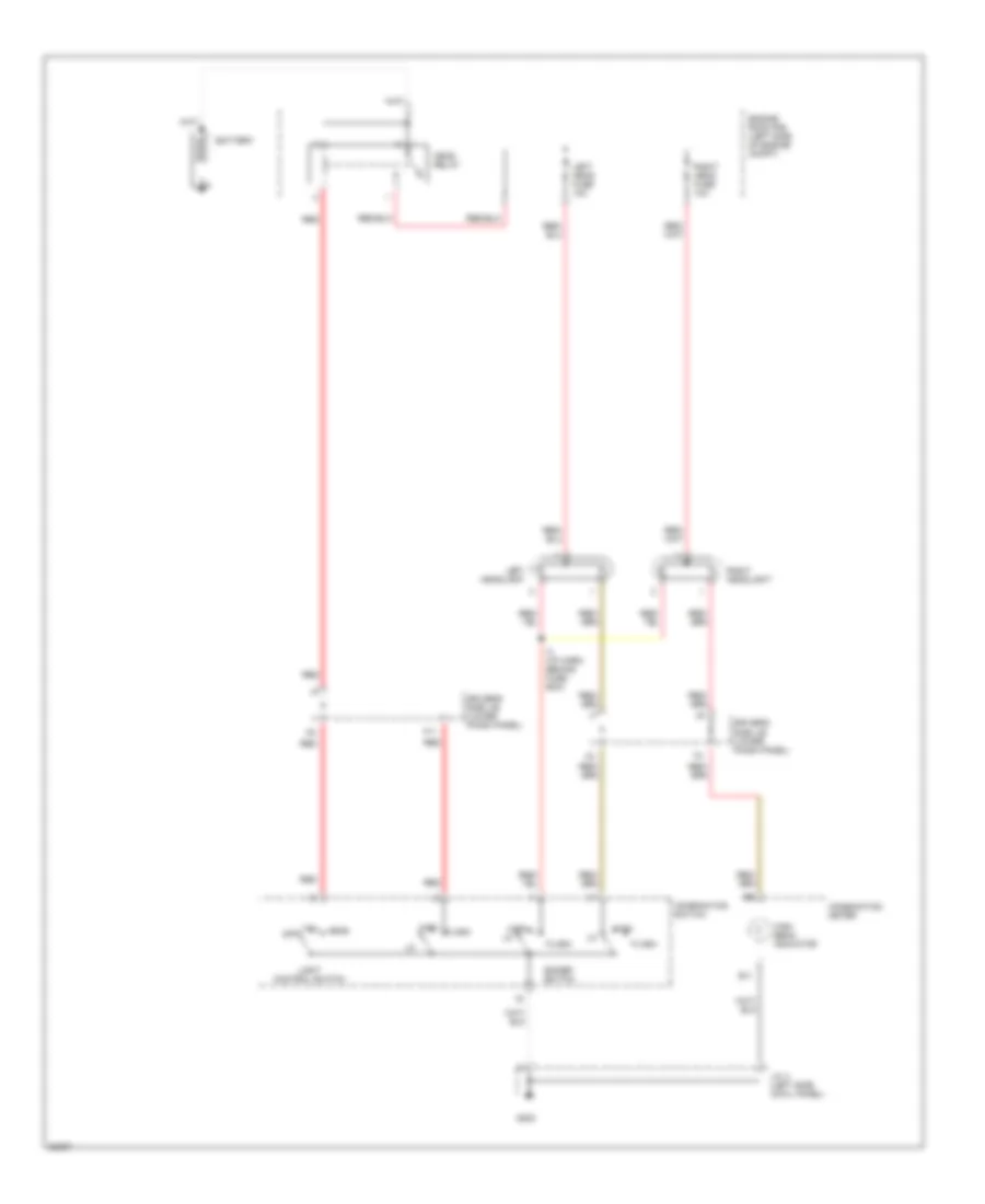
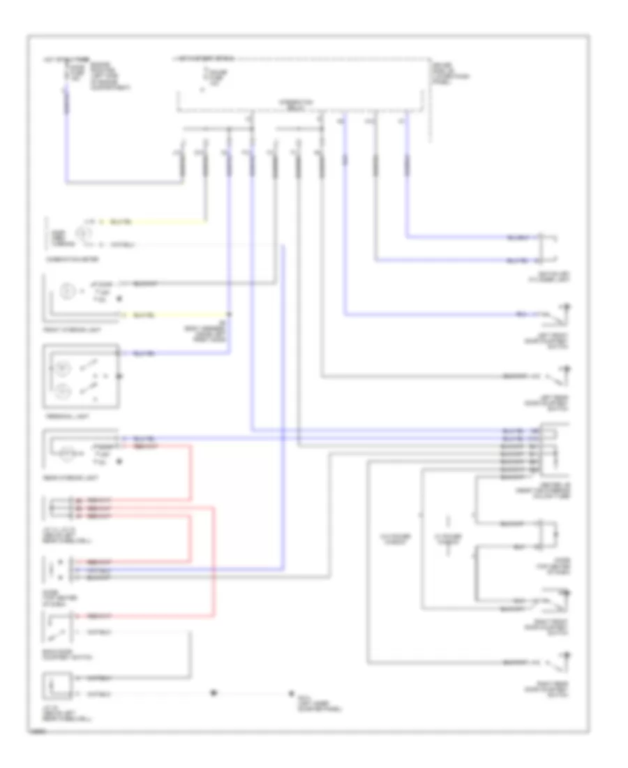
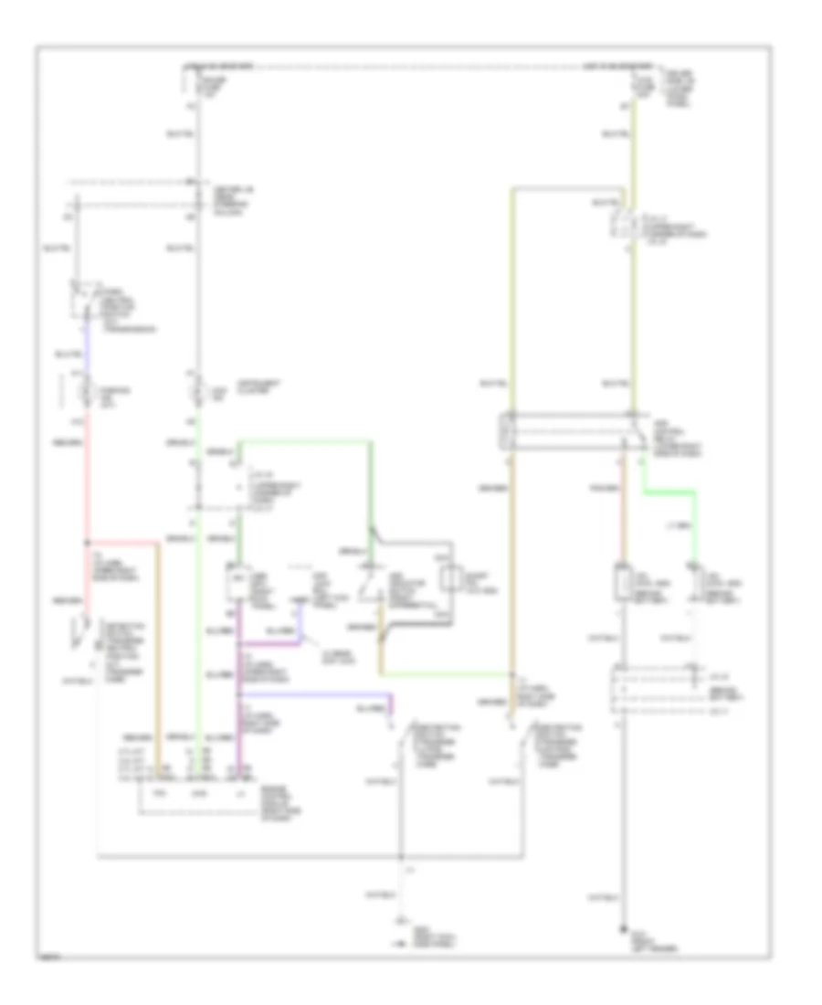
Heater Wiring Diagram for Toyota 4Runner Limited 1996
List of elements for Heater Wiring Diagram for Toyota 4Runner Limited 1996:
- (front left
- (right cowl panel)
- Alt fuse 100a
- Blower motor
- Blower resistor (right side of i/p)
- Blower switch
- Driver side j/b (lower finish panel)
- Engine room r/b (left side of engine compt)
- Fender)
- G100
- G203
- Gauge fuse 10a
- Heater fuse 50a
- Heater relay
- Hot at all times
- Hot in run or start
- Junction connector (left side of engine compt)
- Off
- Red
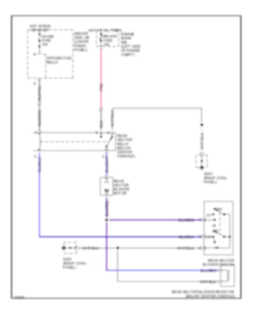
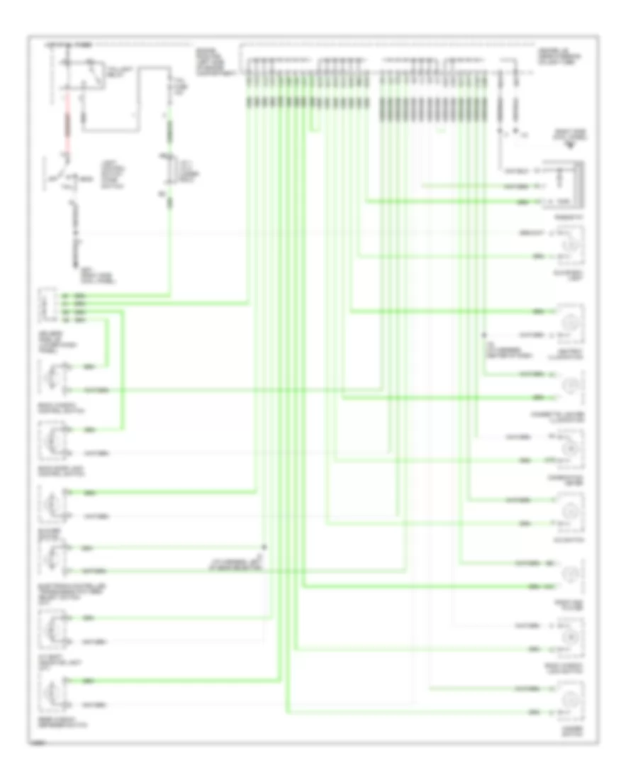
Rear Heater Wiring Diagram for Toyota 4Runner Limited 1996
List of elements for Rear Heater Wiring Diagram for Toyota 4Runner Limited 1996:
- Driver side j/b (lower finish panel)
- Engine room r/b (left side of engine compt)
- G203 (right cowl panel)
- Gauge fuse 10a
- Hot at all times
- Hot in run or start
- Integration relay
- Off
- Pnk
- Rear heater blower motor
- Rear heater blower resistor (below center console)
- Rear heater blower switch
- Rear heater relay (below center console)
- Rr htr fuse 10a
ANTI-LOCK BRAKES
Anti-lock Brake Wiring Diagrams for Toyota 4Runner Limited 1996
List of elements for Anti-lock Brake Wiring Diagrams for Toyota 4Runner Limited 1996:
- 4wd ecu
- A10
- A11
- A12
- A13
- A14
- A15
- A16
- Abs actuator (right inner fender panel)
- Abs deceleration sensor (below center console)
- Abs ecu (right kick panel)
- Abs fuse 60a
- Abs ind
- Abs relay (right rear of eng compt)
- Ast
- B10
- B11
- B12
- B13
- B14
- B15
- B16
- B17
- B18
- B19
- B20
- B21
- B22
- B23
- B24
- B25
- B26
- Batt
- C12
- Combination meter
- Data link connector 1 (left side of engine compt)
- Dome fuse 15a
- Driver side j/b (left side of i/p)
- E3 (eng harn, front of left front fender)
- Ecu-ig fuse 10a
- Engine room r/b (left side of engine compt)
- Exi
- Exi2
- Exo
- F12
- Fl+
- Fl-
- Fr+
- Fr-
- G102 (center of left front fender)
- G103 (center of right front fender)
- G131 (left intake manifold)
- G201 (right side of i/p)
- G202 (left side of i/p)
- Gauge fuse 10a
- Ggnd
- Gnd
- Gs1
- Gs2
- Gst
- Hot at all times
- Hot in on
- I12 (i/p harn, right side of i/p)
- Ig1
- J/b 3 (center of i/p)
- J/c 1/j/c 2 (left side of eng compt)
- J/c 4 (behind left side of dash)
- J/c 7/ j/c 8 (behind glove box)
- J/c 9 (behind right side of dash)
- J12
- Left front abs speed sensor
- Left rear abs speed sensor
- Nca
- Rear diff lock ind light
- Red
- Right front abs speed sensor
- Right rear abs speed sensor
- Rl+
- Rl-
- Rr+
- Rr-
- Sflh
- Sflr
- Sfrh
- Sfrr
- Speedometer
- Srh
- Srr
- Stop fuse 10a
- Stop light switch
- Stp
- W/ 4wd only
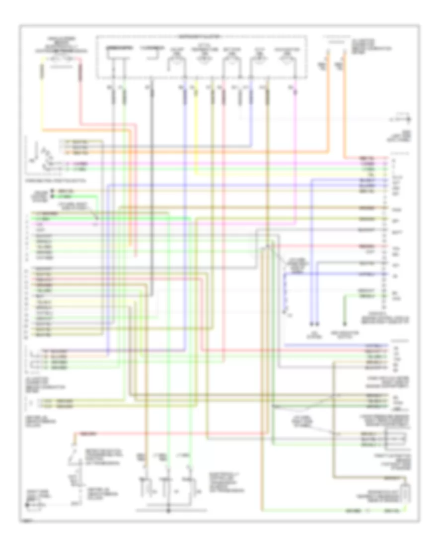
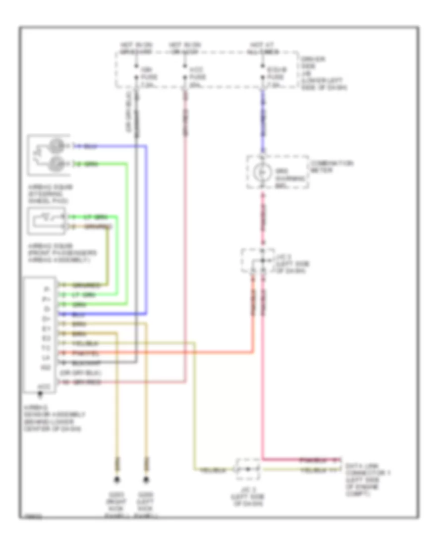
COMPUTER DATA LINES
Computer Data Lines for Toyota 4Runner Limited 1996
List of elements for Computer Data Lines for Toyota 4Runner Limited 1996:
- 2.7 l
- 3.4 l
- A/t
- Abs ecu (right kick panel)
- Abs relay (right rear of engine compt, on inner fender panel)
- Abs warning light (in comb meter)
- B15
- B20
- B25
- Bat
- Center airbag sensor assembly (below center of i/p)
- Center j/b (near steering column tube)
- Cruise control ecu (below center of i/p)
- D19
- Data link connector 1 (left side of engine compt)
- Data link connector 3 (under center left side of dash)
- E15
- E22
- Efi fuse 15a
- Efi relay
- Engine control module (right side of dash)
- Engine control systems
- Engine room r/b (left side of engine compt)
- G131 (intake manifold left)
- G201
- H18
- Hot at all times
- I10
- I11
- I11 (i/p harn, right side of dash)
- I12
- I12 (i/p harn, upper right end of dash)
- Junction connector j3 (left side i/p)
- Junction connector j9 (right side cowl panel)
- M/t
- Obd fuse 7.5a
- Sdl
- Short pin
- Srs warning light (in comb meter)
- Te1
CRUISE CONTROL
Cruise Control Wiring Diagram for Toyota 4Runner Limited 1996
List of elements for Cruise Control Wiring Diagram for Toyota 4Runner Limited 1996:
- (a/t)
- (i/p harness, right side of dash) i11
- (m/t)
- 2.7l engine
- 3.4l engine
- Batt
- C11
- C12
- Cancel
- Ccs
- Center j/b (near steering column tube)
- Cms
- Cruise
- Cruise control actuator (on right inner fender panel)
- Cruise control clutch switch (left side of dash)
- Cruise control ecu (behind center of dash)
- Cruise control ind
- Cruise control switch (combination switch)
- D position switch (park/neutral position switch) (on transmission)
- Data link connector 1 (left side of engine compartment)
- Dome fuse 15a
- Driver side j/b (lower finish panel)
- E10
- E15
- E18
- Ect
- Ecu-ig fuse 10a
- Engine controls system
- Engine room r/b (left side of engine compartment)
- F13
- G201 (right side cowl panel)
- Gauge fuse 10a
- Gnd
- Hot at all times
- Hot in on and start
- I7 (i/p harness, upper center of dash)
- Idl
- Igb
- Instrument cluster
- J/c 1 (center of left fender)
- J/c 9 (right end of dash)
- J12
- N&c
- Pkb
- Red
- Resume/ accel
- Set/ coast
- Spd
- Stop fuse 10a
- Stop light switch (left side of dash)
- Stp+
- Stp-
- To instrument cluster system
- Vr1
- Vr2
- Vr3
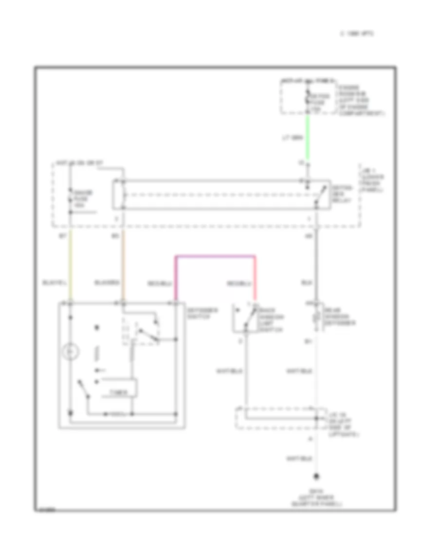
DEFOGGERS
Defogger Wiring Diagram for Toyota 4Runner Limited 1996
List of elements for Defogger Wiring Diagram for Toyota 4Runner Limited 1996:
- Back window limit switch
- C 1995 vftc
- Defog fuse 15a
- Defog- ger relay
- Defogger switch
- Engine room r/b (left side of engine compartment)
- G414 (left inner quarter panel)
- Gauge fuse 10a
- Hot at all times
- Hot in on or st
- J/b 1 (lower finish panel)
- J/c 16 (in left side of liftgate)
- Rear window defogger
- Timer
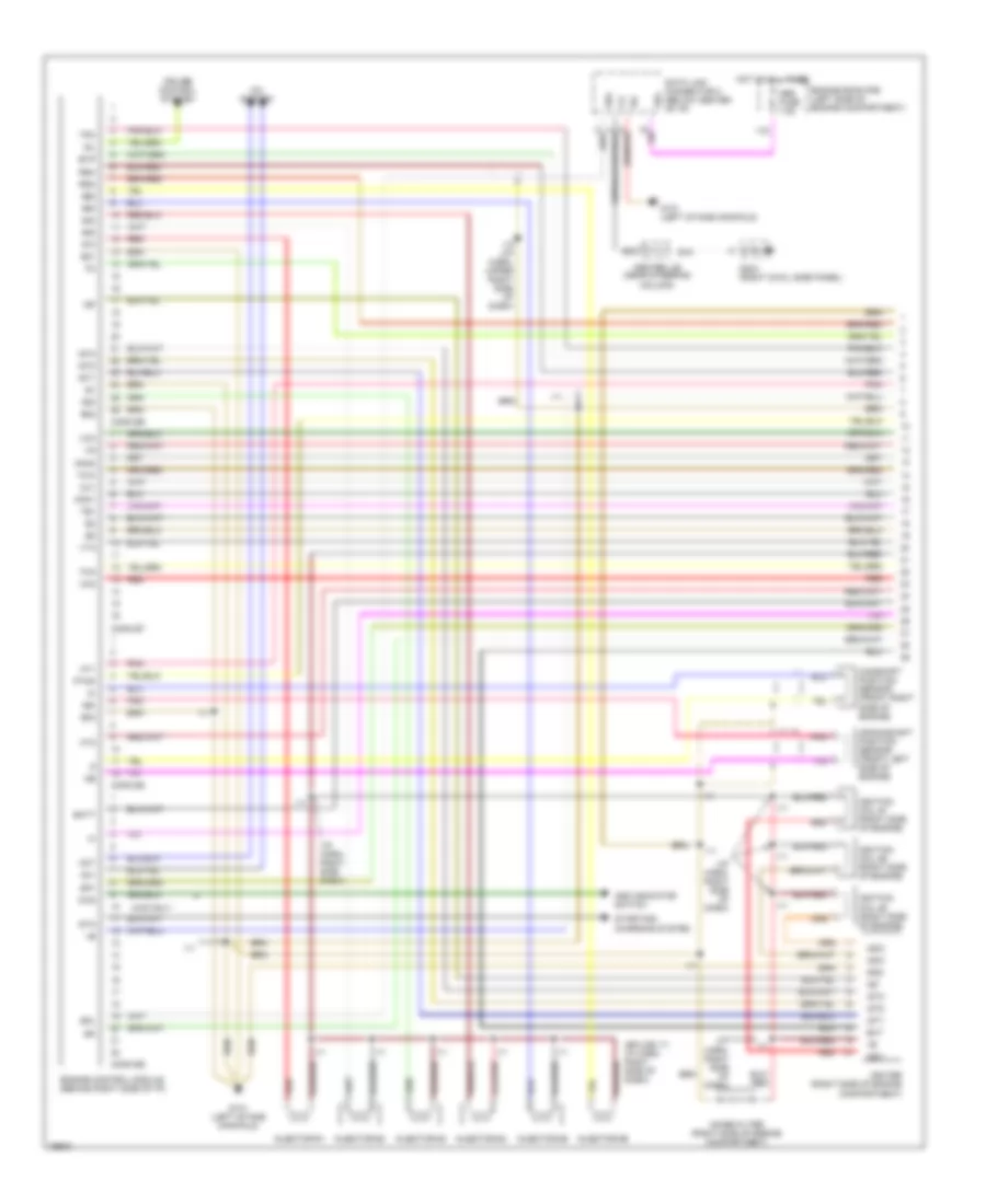
ENGINE PERFORMANCE
2.7L
2.7L, Engine Performance Wiring Diagrams, A/T (1 of 2) for Toyota 4Runner Limited 1996
List of elements for 2.7L, Engine Performance Wiring Diagrams, A/T (1 of 2) for Toyota 4Runner Limited 1996:
- #10
- #20
- (eng harn, top left of engine)
- (i/p harn, behind fuse box)
- (near steering column) center j/b
- (splice i11: i/p harn right side of dash)
- 4wd
- A/c system
- Ac1
- Acc
- Act
- Add ind switch (4wd only)
- Batt
- Conn e6
- Conn e7
- Conn e8
- Conn e9
- Crankshaft position sensor (left side of engine)
- Cruise control system
- Data link connector 1 (left side of engine)
- Distributor (right front of engine)
- Driver side j/b (lower finish panel)
- E01
- E02
- E03
- Egr
- Engine control module (right side of i/p, behind glove box)
- Engine room r/b (left side of engine compartment)
- Evp
- Ext
- G131 (intake manifold)
- Hot at all times
- Hot at all times ignition switch
- Ht1
- Ht2
- I11
- Idl
- Ig-
- Igf
- Igf1
- Ign fuse 7.5a
- Igniter (right side of engine compartment)
- Igt
- Injector #1
- Injector #2
- Injector #3
- Injector #4
- Knk
- Lock
- Ne-
- Noise filter (right side of engine compt)
- Od1
- Od2
- Oil
- Oil-w
- Ox1
- Ox2
- Pnk
- Ptnk
- Pwr
- Red
- Rsc
- Rso
- Run
- Sdl
- Sp1
- Sp2+
- Sp2-
- Sta
- Start
- Start/ charge system
- Stop fuse 10a
- Stop light switch (on brake pedal support)
- Te1
- Tfn
- Tha
- Thg
- Thw
- Tpc
- Vcc
- Vehicle speed sensor (electronically controlled transmission)
- Vta
2.7L, Engine Performance Wiring Diagrams, A/T (2 of 2) for Toyota 4Runner Limited 1996
List of elements for 2.7L, Engine Performance Wiring Diagrams, A/T (2 of 2) for Toyota 4Runner Limited 1996:
- (i/p harn, left kick panel)
- (i/p harn, right side of dash) i11
- (splice i11: i/p harn, right side
- A/t fluid temp switch (in transmission)
- A/t oil temp ind
- A/t p ind
- B11
- Bat
- C11
- C12
- C14
- Cen- ter j/b (near steer col)
- Center j/b (near steering column tube)
- Circuit opening relay (below left side of i/p)
- Cruise control system
- Data link connector 3 (below center of i/p)
- Driver side j/b (lower finish panel)
- Ect pwr ind
- Efi fuse 15a
- Efi relay (engine room r/b)
- Egr gas temp sensor (left side of engine)
- Egr vsv (left side of engine)
- Electronically controlled trans pattern select sw
- Electronically controlled transmission solenoid (on transmission)
- Engine coolant temp sensor (top rear of engine)
- Engine room r/b (left side of engine compartment)
- Engine room r/b (left side of engine compt)
- Evap vsv (left side of engine compartment)
- Fuel pump
- G100 (front left fender)
- G131 (intake manifold)
- G200 (left cowl side panel)
- G202 (left cowl side panel)
- G203 (right cowl side panel)
- Gauge fuse 10a
- Heated oxygen sensor (bank 1 sensor 1) (below rear of engine compt)
- Heated oxygen sensor (bank 1 sensor 2) (below rear of engine compt)
- Hot at all times
- Hot in run or start
- I11
- Idle air control valve (left side of engine)
- Instrument cluster
- Intake air temp sensor (on air cleaner assembly)
- J/c j6 (left dash)
- Knock sensor (left side of engine)
- Mal- function ind
- Mass air flow meter (on air cleaner assembly)
- O/d main sw
- O/d off ind
- Obd fuse 7.5a
- Of dash)
- Park/neutral position switch (on transmission)
- Pnk
- Ptnk
- Red
- Sdl
- Speedo
- Tach
- Throttle position sensor (left side of engine)
- Vapor pressure sensor (left rear corner of engine compartment)
- Vapor pressure sensor vsv (left side of engine compt)
- Vcc
2.7L, Engine Performance Wiring Diagrams, M/T (1 of 2) for Toyota 4Runner Limited 1996
List of elements for 2.7L, Engine Performance Wiring Diagrams, M/T (1 of 2) for Toyota 4Runner Limited 1996:
- #10
- #20
- (eng harn, top left of engine)
- (splice i11: i/p harn, right of dash)
- 4wd
- A/c system
- Ac1
- Acc
- Act
- Add indicator switch (4wd only)
- Batt
- Center j/b (near steering column)
- Conn e6
- Conn e7
- Conn e9
- Crankshaft position sensor (left side of engine)
- Data link connector 1 (left side of engine)
- Distributor (right front of engine)
- Driver side j/b (lower finish panel)
- E01
- E02
- E03
- Egr
- Engine control module (right side of i/p, behind glove box)
- Engine room r/b (left side of engine compartment)
- Evp
- Ext
- G131 (intake manifold)
- Hot at all times
- Ht1
- Ht2
- I10
- I11
- Idl
- Ig-
- Igf
- Igf1
- Ign fuse 7.5a
- Igniter (right side of engine compartment)
- Ignition switch
- Igt
- Injector #1
- Injector #2
- Injector #3
- Injector #4
- Knk
- Lock
- Ne-
- Noise filter (right side of engine compt)
- Ox1
- Ox2
- Pnk
- Ptnk
- Red
- Rsc
- Rso
- Run
- Sdl
- Sp1
- Sta
- Start
- Starting/charging system
- Stop fuse 10a
- Stop light switch (on brake pedal support)
- Te1
- Tha
- Thg
- Thw
- Tpc
- Vcc
- Vta
2.7L, Engine Performance Wiring Diagrams, M/T (2 of 2) for Toyota 4Runner Limited 1996
List of elements for 2.7L, Engine Performance Wiring Diagrams, M/T (2 of 2) for Toyota 4Runner Limited 1996:
- (i/p harn, left kick panel)
- (i/p harn, right side of dash)
- (splice i11: i/p harn, right side of dash)
- Bat
- C12
- C14
- Cen- ter j/b (near steer col)
- Center j/b (near steering column tube)
- Center j/b (neer steering column)
- Circuit opening relay (below left side of i/p)
- Data link connector 3 (below center of i/p)
- Driver side j/b (lower finish panel)
- E15
- E22
- Efi fuse 15a
- Efi relay (engine room r/b)
- Egr gas temp sensor (left side of engine)
- Egr vsv (left side of engine)
- Engine coolant temp sensor (top rear of engine)
- Engine room r/b (left side of engine compartment)
- Engine room r/b (left side of engine compt)
- Evap vsv (left side of engine compartment)
- Fuel pump
- G100 (front left fender)
- G131 (intake manifold)
- G200 (left cowl side panel)
- G203 (right cowl side panel)
- Gauge fuse 10a
- Heated oxygen sensor (bank 1 sensor 1) (below rear of engine compt)
- Heated oxygen sensor (bank 1 sensor 2) (below rear of engine compt)
- Hot at all times
- Hot in run or start
- I10
- I11
- Idle air control valve (left side of engine)
- Instrument cluster
- Intake air temp sensor (on air cleaner assembly)
- J/c j12 (near left rear door sill)
- J/c j2 (top of battery) j/c j1 (top of battery)
- Knock sensor (left side of engine)
- Mal- function ind
- Mass air flow meter (on air cleaner assembly)
- Obd fuse 7.5a
- Pnk
- Ptnk
- Red
- Sdl
- Speedo
- Tach
- Throttle position sensor (left side of engine)
- Vapor pressure sensor (left rear corner of engine compartment)
- Vapor pressure sensor vsv (left side of engine compt)
- Vcc
3.4L
3.4L, Engine Performance Wiring Diagrams, A/T (1 of 3) for Toyota 4Runner Limited 1996
List of elements for 3.4L, Engine Performance Wiring Diagrams, A/T (1 of 3) for Toyota 4Runner Limited 1996:
- #10
- #20
- #30
- #40
- #50
- #60
- (i/p harn, right side of
- (i/p harn, right side of dash)
- A/t fluid temperature sensor (on transmission)
- A/t fluid temperature switch (on transmission)
- Camshaft position sensor (front right side of engine)
- Center j/b (near str col)
- Conn e10
- Conn e11
- Conn e12
- Crankshaft position sensor (front left side of engine)
- Cruise control system
- Dash)
- Data link connector 3 (below center of i/p)
- E02
- E03
- E15
- E22
- Engine control module (behind right side of i/p)
- Engine room r/b (left side of engine compartment)
- Evp
- Ext
- F13
- G131 (left intake manifold)
- G203 (right cowl side panel)
- Gnd
- Hot at all times
- Ht1
- Ht2
- I11
- Idl
- Igc1
- Igc2
- Igc3
- Igf
- Igniter (right side of engine compartment)
- Ignition coil #1 (right side of engine)
- Ignition coil #2 (right side of engine)
- Ignition coil #3 (right side of engine)
- Igt1
- Igt2
- Igt3
- Injector #1
- Injector #2
- Injector #3
- Injector #4
- Injector #5
- Injector #6
- Knk1
- Knk2
- Ne-
- Noise filter (right side of engine compartment)
- Obd fuse 7.5a
- Oil
- Ox1
- Ox2
- Pnk
- Ptnk
- Red
- Rsc
- Rso
- Sdl
- Sp2-
- Sta
- Starting/charging system
- Te1
- Tha
- Thw
- Tpc
- Vcc
- Vta
3.4L, Engine Performance Wiring Diagrams, A/T (2 of 3) for Toyota 4Runner Limited 1996
List of elements for 3.4L, Engine Performance Wiring Diagrams, A/T (2 of 3) for Toyota 4Runner Limited 1996:
- (front left fender) g100
- (i/p harn, behind fuse block)
- (near left rear door sill) j/c j12
- (splice i11: i/p harn, right side of dash)
- (top of battery) j/c j1
- Acc
- Center j/b (near steering column tube)
- Circuit opening relay (below left side of i/p)
- Data link connector 1 (left side of engine)
- Driver side j/b (lower finish panel)
- Efi fuse 15a
- Efi relay
- Engine room r/b (left side of engine compartment)
- Evap vsv (left side of engine compartment)
- Fuel pump
- G200 (left cowl side panel)
- Gauge fuse 7.5a
- Heated oxygen sensor (bank 1 sensor 1) (below rear of engine compartment)
- Heated oxygen sensor (bank 1 sensor 2) (below rear of engine compartment)
- Hot at all times
- Hot in start or run
- I10 (i/p harn, upper right side of dash)
- I11
- I2 (i/p harn, left kick panel)
- Idle air control valve (top right rear of engine)
- Ign fuse 7.5a
- Ignition switch
- J/c j2 (top of battery)
- Knock sensor #1 (top front of engine)
- Knock sensor #2 (top front of engine)
- Lock
- Pnk
- Red
- Run
- Start
- Stop fuse 10a
- Stop light switch (on brake pedal support)
- Te1
- Vapor pressure sensor vsv (left side of engine compartment)
3.4L, Engine Performance Wiring Diagrams, A/T (3 of 3) for Toyota 4Runner Limited 1996
List of elements for 3.4L, Engine Performance Wiring Diagrams, A/T (3 of 3) for Toyota 4Runner Limited 1996:
- (i/p harn, right side of dash)
- (i/p harn, upper right side of dash)
- (right side cowl panel) g203
- 4wd
- A/c system
- A/t oil temperature ind
- A/t p ind
- Ac1
- Act
- Add indicator switch
- Batt
- C12
- C14
- Center j/b (near steering column)
- Conn e13
- Cruise control system
- Detection switch (transfer neutral position) (on transmission)
- E15
- Ect pwr ind
- Electroniclly controlled transmission solenoid (on transmission)
- Engine control module (behind right side of i/p)
- Engine coolant temperature sensor (rear of engine)
- G200 (left side cowl panel)
- I10
- I11
- Instrument cluster
- J5 junction connector (behind combination meter)
- J6 junction connector (behind combination meter)
- Malfunction ind
- Mass air flow meter (right side of engine compartment)
- O/d off ind
- Od1
- Od2
- Oil-w
- Park/neutral position switch
- Ptnk
- Pwr
- Sdl
- Sp1
- Speedometer
- Tachometer
- Tfn
- Tha
- Throttle position sensor (top right side of engine)
- Vapor pressure sensor (right rear corner of engine compartment)
- Vcc
- Vehicle speed sensor (electronically controlled transmission)
3.4L, Engine Performance Wiring Diagrams, M/T (1 of 2) for Toyota 4Runner Limited 1996
List of elements for 3.4L, Engine Performance Wiring Diagrams, M/T (1 of 2) for Toyota 4Runner Limited 1996:
- #10
- #20
- #30
- #40
- #50
- #60
- (i/p harn, right side dash)
- (i/p harn, right side of dash)
- (splice i11: i/p harn, right side of dash)
- 4wd
- 4wd only
- A/c system
- Ac1
- Act
- Add indicator switch
- Batt
- Camshaft position sensor (front right side of engine)
- Center j/b (near steering
- Column)
- Conn e6
- Conn e7
- Conn e8
- Conn e9
- Crankshaft position sensor (front left side of engine)
- Cruise control system
- Data link connector 3 (below center of i/p)
- E01
- E02
- E03
- E15
- E22
- Engine control module (behind right side of i/p)
- Engine room r/b (left side of engine compartment)
- Evp
- Ext
- G131 (left intake manifold)
- G203 (right cowl side panel)
- Gnd
- Hot at all times
- Ht1
- Ht2
- I10 (i/p harn, upper right side of dash)
- I11
- Idl
- Igc1
- Igc2
- Igc3
- Igf
- Igniter (right side of engine compartment)
- Ignition coil #1 (right side of engine)
- Ignition coil #2 (right side of engine)
- Ignition coil #3 (right side of engine)
- Igt1
- Igt2
- Igt3
- Injector #1
- Injector #2
- Injector #3
- Injector #4
- Injector #5
- Injector #6
- Knk1
- Knk2
- Ne-
- Noise filter (right side of engine compartment)
- Obd fuse 7.5a
- Ox1
- Ox2
- Pnk
- Ptnk
- Red
- Rsc
- Rso
- Sdl
- Sp1
- Sta
- Starting/ charging system
- Te1
- Tha
- Thw
- Tpc
- Vcc
- Vta
3.4L, Engine Performance Wiring Diagrams, M/T (2 of 2) for Toyota 4Runner Limited 1996
List of elements for 3.4L, Engine Performance Wiring Diagrams, M/T (2 of 2) for Toyota 4Runner Limited 1996:
- (front left fender) g100
- (i/p harn, behind fuse block) i3
- (i/p harn, left kick panel)
- (i/p harn, upper right side of dash) i10
- (near left rear door sill) j/c j12
- (splice i11: i/p harn, right side of dash)
- (top of battery j/c j1
- Acc
- Center j/b (near steering column tube)
- Circuit opening relay (below left side of i/p)
- Data link connector 1 (left side of engine)
- Driver side j/b (lower finish panel)
- Efi fuse 15a
- Efi relay
- Engine coolant temperature sensor (rear of engine)
- Engine room r/b (left side of engine compartment)
- Evap vsv (left side of engine compartment)
- Fuel pump
- G200 (left cowl side panel)
- Gauge fuse 7.5a
- Heated oxygen sensor (bank 1 sensor 1) (below rear of engine compartment)
- Heated oxygen sensor (bank 1 sensor 2) (below rear of engine compartment)
- Hot at all times
- Hot in start or run
- I11
- Idle air control valve (top right rear of engine)
- Ign fuse 7.5a
- Ignition switch
- Instrument cluster
- J/c j2 (top of battery)
- Knock sensor #1 (top front of engine)
- Knock sensor #2 (top front of engine)
- Lock
- Malfunction ind lp
- Mass air flow meter (right side of engine compartment)
- Pnk
- Ptnk
- Red
- Run
- Speed input
- Start
- Stop fuse 10a
- Stop light switch (on brake pedal support)
- Tach
- Te1
- Tha
- Throttle position sensor (top right side of engine)
- Vapor pressure sensor (right rear corner of engine compartment)
- Vapor pressure sensor vsv (left side of engine compartment)
- Vcc
EXTERIOR LIGHTS
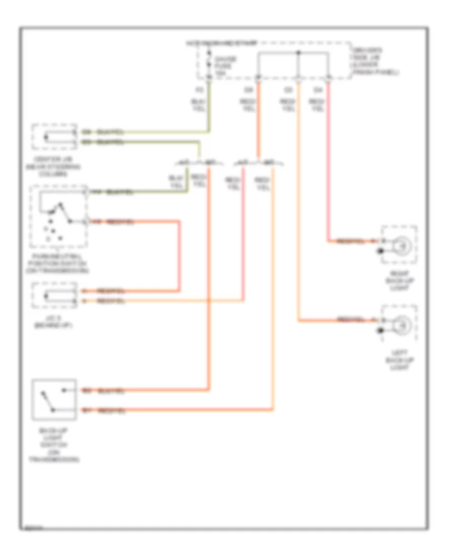
Back-up Lamps Wiring Diagram for Toyota 4Runner Limited 1996
List of elements for Back-up Lamps Wiring Diagram for Toyota 4Runner Limited 1996:
- A/t
- Back-up light switch (on transmission)
- Center j/b (near steering column)
- Driver's side j/b (lower finish panel)
- Gauge fuse 10a
- Hot in on and start
- J/c 5 (behind i/p)
- Left back-up light
- M/t
- Park/neutral position switch (on transmission)
- Right back-up light
Exterior Lamps Wiring Diagram for Toyota 4Runner Limited 1996
List of elements for Exterior Lamps Wiring Diagram for Toyota 4Runner Limited 1996:
- (center of dash) i7
- (left side of dash) i5
- Alt fuse 100a
- B10
- Center j/b (near steering column)
- Combination meter
- Combination switch
- Driver's side j/b (lower finish panel)
- E13
- E15
- E20
- Engine room r/b (left side of engine compartment)
- G104 (front of left fender)
- G201
- G202
- G414 (left inner quarter panel)
- Hazard switch
- Head
- High mounted stop light
- Horn fuse 15a
- Hot at all times
- Hot in on or start
- Integration relay
- J/c 1 (near battery)
- J/c 14 (front of left quarter panel)
- J/c 16 (left side of liftgate)
- J/c 4 (left side cowl panel)
- J/c 9 (right side cowl panel)
- J10
- J11
- Left front parking light
- Left front turn signal light
- Left rear combination lamp
- Left turn
- License plate light
- Light switch
- Off
- Right front parking light
- Right front turn signal light
- Right rear combination lamp
- Right turn
- Stop
- Stop fuse 10a
- Stop light switch (above brake pedal)
- Tail
- Tail fuse 10a
- Tail relay
- Turn
- Turn fuse 10a
- Turn signal flasher
- Turn signal switch
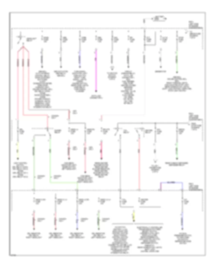
GROUND DISTRIBUTION
Ground Distribution Wiring Diagram (1 of 3) for Toyota 4Runner Limited 1996
List of elements for Ground Distribution Wiring Diagram (1 of 3) for Toyota 4Runner Limited 1996:
- (2wd) vacuum solenoid valve
- (4wd) vacuum solenoid valve
- (left side of of engine compartment) r/b 1
- Abs actuator
- Abs ecu
- Abs relay
- Airbag sensor assembly
- B11
- B2 (body harness, inside left front door)
- B24
- B4 (body harness, above center of windshield)
- B9 (body harness, under driver's seat)
- Brake fluid level warning switch
- Buckle switch
- Cigarette lighter
- Clock
- Combination meter
- Daytime running light resistor
- Dimmer switch
- E3 (engine harness, left front fender apron)
- Efi relay
- Front wiper and washer switch
- Fuel pump
- G104 (front left fender)
- G105 (front right fender)
- G202 (left side cowl panel)
- G203 (right kick panel)
- Glove box light
- Heater relay
- I5 (i/p harness, upper left side of dash)
- I7 (i/p harness, upper center of dash)
- J/c 1 & 2 (under r/b 2)
- J/c 12 & 13 (under left rear seat)
- J/c 4 (upper left end of dash)
- Left front door key lock & unlock switch
- Left front door lock control switch
- Left front door lock motor & door unlock detection switch
- Left front parking light
- Left front turn signal light
- Light control switch
- Moon roof control motor & limit switch
- Moon roof control relay
- Moon roof control switch
- Power seat control switch (driver's seat lumbar support)
- Power seat control switch (driver's side)
- Power window master switch
- Rear differential lock detection switch
- Rear differential lock motor
- Right front parking light
- Right front turn signal light
- To j/b 3 pin 13 (diagram 2 of 3)
- To junction connector 9 (diagram 3 of 3)
- W/o power seats
- W/o power windows
- With power seat
- With power windows
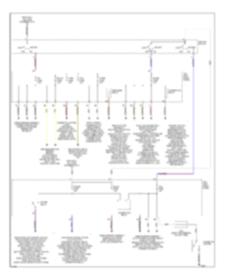
Ground Distribution Wiring Diagram (2 of 3) for Toyota 4Runner Limited 1996
List of elements for Ground Distribution Wiring Diagram (2 of 3) for Toyota 4Runner Limited 1996:
- (lower finish panel) j/b 1
- 2-4 select motor
- 2-4 select switch
- 4wd control ecu
- 4wd ecu
- A/c amplifier
- A/c switch
- Auto antenna control relay
- B5 (body harness, inside right front door)
- Brake fluid level warning switch
- Canada
- Clutch start cancel switch
- Clutch start switch
- Cruise control ecu
- Cruise control main switch
- Data link connector 3
- Daytime running light relay (main)
- Daytime running light relay no. 4
- Detection switch (transfer 4wd position)
- Detection switch (transfer l4 position)
- Detection switch (transfer neutral position)
- From j/c 4 (diagram 1 of 3)
- I11 (i/p harness, right side of dash)
- I13 (i/p harness, upper right end of dash)
- I4 (i/p harness, upper left end of dash)
- I5 (i/p harness, upper left side of dash)
- I7 (canada only) (i/p harness, upper center of dash)
- I7 (i/p harness, upper center of dash)
- I9 (i/p harness, behind center a/c vents)
- Ii3
- Integration relay
- J/b 3 (near the steering column tube)
- O/d main switch
- Park/ neutral position switch
- Power relay
- Rheostat
- Right front door key lock & unlock switch
- Right front door lock control switch
- Right front door lock motor & door unlock detection switch
- Shift lock control computer
- To power seat control switch (diagram 3 0f 3)
- Turn signal flasher
- Unlock warning switch
- Washer level fluid switch
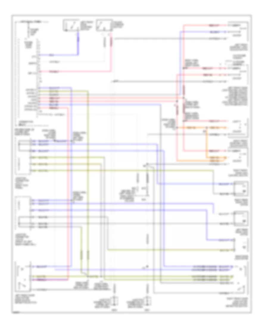
Ground Distribution Wiring Diagram (3 of 3) for Toyota 4Runner Limited 1996
List of elements for Ground Distribution Wiring Diagram (3 of 3) for Toyota 4Runner Limited 1996:
- 3rz-fe: 2.7l
- 5v2-fe: 3.4l
- A/t
- A12 c12
- A13
- A24
- A26
- Abs ecu
- Airbag sensor assembly
- B11
- B6 (body harness, above left side of liftgate)
- B8 (body harness, under right front seat)
- Back door courtesy switch
- Back door lock control switch
- Back window limit switch
- Back window lock switch
- Blower resistor
- Blower switch
- Combination meter
- Data link connector 1
- Data link connector 3
- E33
- E34
- Engine control module
- From j/b 3 (diagram 2 of 3)
- From light control switch (diagram 1 of 3)
- Fuel sender
- G110 (near intake manifold)
- G16
- G200 (left kick panel)
- G201 (right side cowl panel)
- G414 (left inner quarter panel)
- Heated oxygen sensor (bank 1, sensor 1)
- Heated oxygen sensor (bank 1, sensor 2)
- High mounted stop light
- I11 (i/p harness, right side of dash)
- I12 (i/p harness, upper right side of dash)
- I7 (i/p harness, upper center of dash)
- Igniter
- J/b 3 (near the steering column tube)
- J/c 16 (in left side of liftgate)
- J/c 9 (right end of dash)
- License plate light
- M/t
- Noise filter
- Power seat control switch (front right seat)
- Power window relay
- Radio & player
- Rear heater blower resistor
- Rear heater blower switch
- Rear heater relay
- Rear window defogger
- Rear wiper motor
- Remote control mirror switch
- Tailgate control switch
HEADLIGHTS
Headlight Wiring Diagram, with DRL for Toyota 4Runner Limited 1996
List of elements for Headlight Wiring Diagram, with DRL for Toyota 4Runner Limited 1996:
- (i/p harn, behind fuse box) i3
- B12
- Battery
- Brake fluid level switch (left rear of engine compt)
- Center j/b (near steering column)
- Combination meter
- Combination switch
- Daytime running light relay (center of dash)
- Daytime running light relay 4 (right side of dash)
- Daytime running light resistor (front of left fender)
- Dimmer relay
- Dimmer switch
- Dome fuse 15a
- Driver's side j/b (lower finish panel)
- Drl diode 1 (behind glove compartment)
- Drl diode 2 (behind glove compartment)
- Drl fuse 7.5a
- E11
- E13
- Engine room r/b (right side of engine compt)
- F12
- Flash
- G104 (front of left fender)
- G202
- Gauge fuse 10a
- Head
- Head relay
- High
- High beam indicator
- Hot at all times
- Hot in on or start
- I13
- I5 (i/p harn, upper left side of dash)
- I6 (i/p harn, behind left side of radio)
- J/c 1 (center of left fender)
- J/c 4 (left side cowl panel)
- J/c 7 (right side of dash)
- J12
- Left headlight
- Left hi head fuse 10a
- Left lo head fuse 10a
- Light control switch
- Off
- Parking brake switch
- Red
- Right headlight
- Right hi head fuse 10a
- Right lo head fuse 10a
- Starting/ charging system
- Tail
Headlight Wiring Diagram, without DRL for Toyota 4Runner Limited 1996
List of elements for Headlight Wiring Diagram, without DRL for Toyota 4Runner Limited 1996:
- B11
- Battery
- Combination switch
- Conbination meter
- Dimmer switch
- Driver's side j/b (lower finish panel)
- Engine room r/b (left side of engine compt)
- F11
- Flash
- G202
- Head
- Head relay
- High
- High beam indicator
- I3 (i/p harn, behind fuse box)
- J/c 4 (left side cowl panel)
- Left head fuse 10a
- Left headlight
- Light control switch
- Off
- Red
- Right head fuse 10a
- Right headlight
- Tail
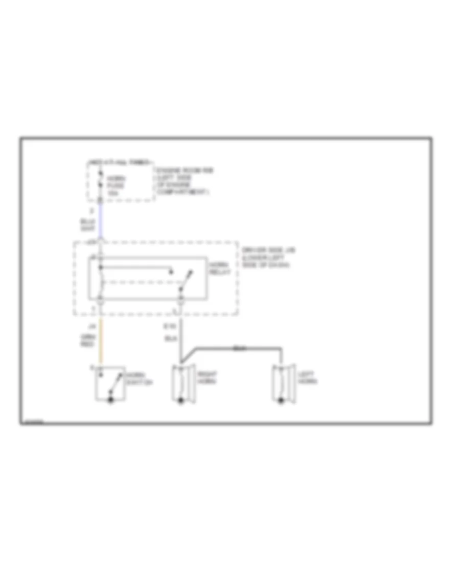
HORN
Horn Wiring Diagram for Toyota 4Runner Limited 1996
List of elements for Horn Wiring Diagram for Toyota 4Runner Limited 1996:
- Driver side j/b (lower left side of dash)
- E10
- Engine room r/b (left side of engine compartment)
- Horn fuse 15a
- Horn relay
- Horn switch
- Hot at all times
- Left horn
- Right horn
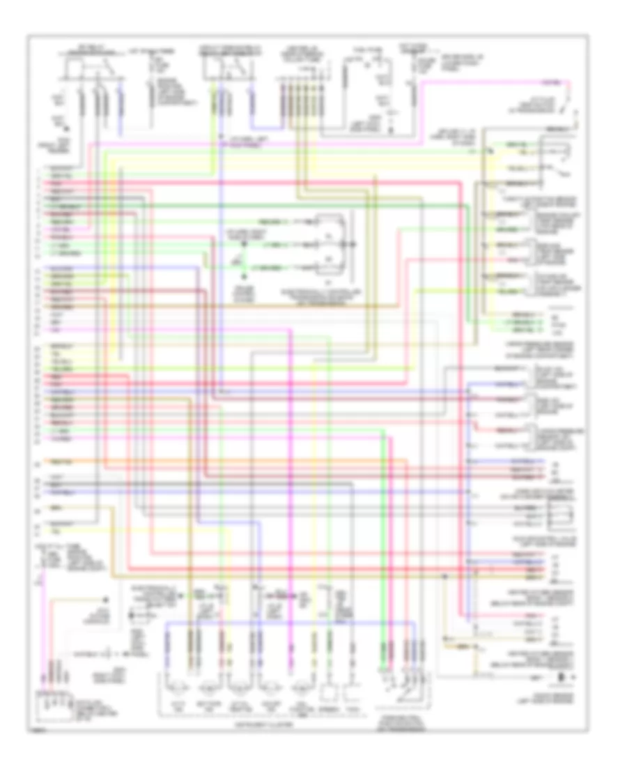
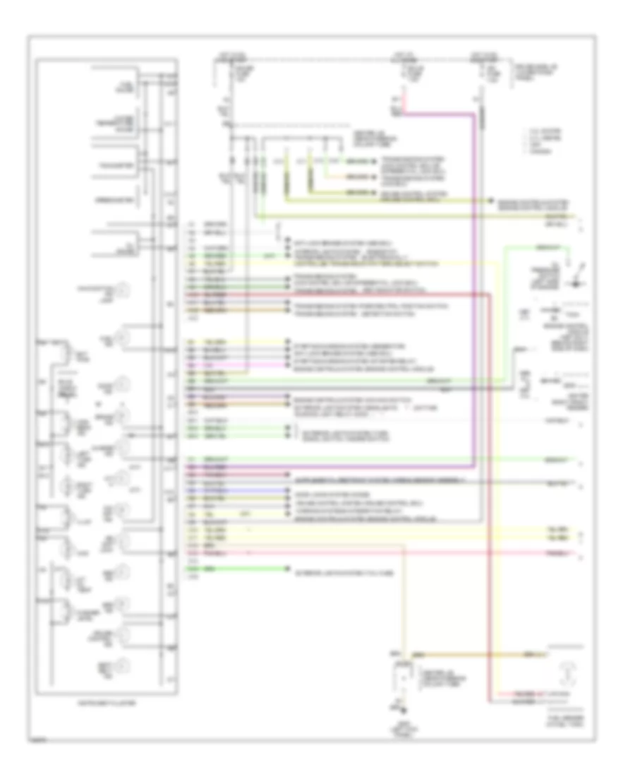
INSTRUMENT CLUSTER
Instrument Cluster Wiring Diagram (1 of 2) for Toyota 4Runner Limited 1996
List of elements for Instrument Cluster Wiring Diagram (1 of 2) for Toyota 4Runner Limited 1996:
- (4wd control ecu or differential lock ecu)
- (a/t)
- (add indicator switch)
- (detection switch)
- (electronically
- (rheostat)
- , daytime
- 2.7l
- 2.7l (3rz-fe)
- 3.4l (5vz-fe)
- 4wd
- A/t
- A/t oil temp
- A10
- A11
- A12
- A13
- Abs ind
- All & 3.4l
- Anti-lock brakes system (abs ecu)
- B10
- B11
- B12
- B13
- Brake ind
- Bulb check relay
- C10
- C11
- C12
- C13
- C14
- C15
- C16
- Canada
- Center j/b (near steering column tube)
- Charge ind
- Controlled transmission pattern select switch)
- Cruise control ind
- Cruise control system (cruise control ecu)
- D3 c12
- Door ind
- Door locks system (diode)
- Driver side j/b (lower finish panel)
- Ect pwr
- Ecu-b fuse 7.5a
- Engine control module (1997 only) (behind right side of dash)
- Engine controls system (engine control module)
- Engine controls system (o/d main switch)
- Ext
- Exterior lights system (headlights running light relay (main) )
- Exterior lights system (tail fuse)
- Exterior lights system (turn signal switch, hazard switch)
- Fuel gauge
- Fuel ind
- Fuel sender (in fuel tank)
- G200 (left kick panel)
- Gauge fuse 10a
- High beam ind
- Hot at all times
- Hot in on and start
- Ign fuse 7.5a
- Igniter (right front) fender)
- Illum
- Instrument cluster
- Interior lights system transmissions system
- Left turn ind
- Malfunction ind lamp
- O/d off ind
- Oil gauge
- Oil pressure switch (left side of engine)
- Right turn ind
- Rr diff lock
- Seat belt ind
- Speedometer
- Srs ind
- Starting/charging system (generator)
- Starting/charging system (starter relay)
- Tach
- Tachometer
- Transmissions system
- Transmissions system (4wd control ecu or differential lock ecu)
- Transmissions system (4wd ecu)
- Transmissions system (park/neutral position switch)
- Usa
- Warning systems (integration relay)
- Washer level
- Water temperature gauge
Instrument Cluster Wiring Diagram (2 of 2) for Toyota 4Runner Limited 1996
List of elements for Instrument Cluster Wiring Diagram (2 of 2) for Toyota 4Runner Limited 1996:
- 2.7l (3rz-fe)
- 3.4l (5vz-fe)
- Acc fuse 15a
- Brake fluid level warning switch (on brake fluid reservoir)
- Canada
- Center j/b (near power steering column tube)
- Center j/b (near steering column tube)
- Clock
- D10
- D13
- D19
- Dome fuse 15a
- Driver side j/b (lower finish panel)
- E11
- E15
- F11
- F12
- F18
- G104 (front left fender)
- G201 (right side cowl panel)
- G202 (left side cowl panel)
- Headlights systm (daytime running light relay (main))
- Hot at all times
- Hot in on and acc
- J/c 1, 2 (left front fender)
- J/c 4 (upper left end of dash)
- J/c 7, 8 (right side of dash)
- J/c 9 (right end of dash)
- J12
- Parking brake switch (on base of park brake lever)
- R/b 2 (right side of engine compartment)
- Speed sensor (combination meter)
- Tail fuse 10a
- Usa
- Vehicle
- Washer level warning switch (right front fender)
- Water temperature sender (rear of engine)
INTERIOR LIGHTS
Courtesy Lamps Wiring Diagram for Toyota 4Runner Limited 1996
List of elements for Courtesy Lamps Wiring Diagram for Toyota 4Runner Limited 1996:
- A12
- B3 (body harness, inside left front door)
- Back door courtesy switch
- C10
- Center j/b (near the steering column tube)
- Combination meter
- Diode (top center of dash)
- Dome fuse 15a
- Door
- Door open warning
- Driver side j/b (lower finish panel)
- Engine room r/b (left side of engine compartment)
- Front interior light
- G414 (left inner quarter panel)
- Gauge fuse 10a
- Hot at all times
- Hot in start or run
- Igntion key cylinder light
- Integration relay
- J/c 14, j/c 15 (above left rear wheelwell)
- J/c 16 (above left rear wheelwell)
- Left front door courtesy switch
- Left rear door courtesy switch
- Off
- Personal light
- Rear interior light
- Right front door courtesy switch
- Right rear door courtesy switch
- W/ power window
- W/o power window
Instrument Illumination Wiring Diagram for Toyota 4Runner Limited 1996
List of elements for Instrument Illumination Wiring Diagram for Toyota 4Runner Limited 1996:
- (right side cowl panel) g201
- A/c switch
- A/t shift indicator light (a/t)
- A10
- Ashtray illumination
- Back door lock control switch
- Back window control switch
- Back window lock switch
- Blower switch
- C15
- C17
- C18
- C19
- C20
- C21
- C22
- Center j/b (near steering column tube)
- Cigarette lighter illumination
- Combination meter
- D13
- D14
- D15
- D16
- D17
- D18
- D20
- Driver's side j/b (lower finish panel)
- E11
- E15
- Electronic controlled transmission pattern select switch (a/t)
- Engine room r/b (left side of engine compartment)
- F11
- F13
- F14
- F15
- F16
- F17
- F18
- F19
- F20
- G201 (right side cowl panel)
- Glove box light
- Hazard switch
- Head
- Hot at all times
- I12
- I16 (i/p harness, center of dash)
- I8 (i/p harness, left of gear selector)
- J/c 1, j/c 2 (under r/b 2)
- Light control switch (comb switch)
- Off
- Radio and player
- Rear window defogger switch
- Rheostat
- Tail
- Tail fuse 10a
- Taillight relay
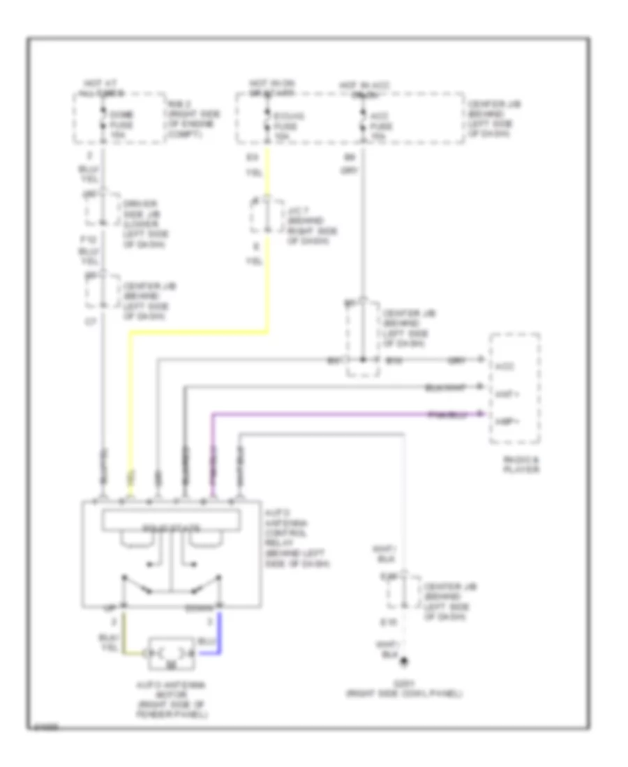
POWER ANTENNA
Power Antenna Wiring Diagram for Toyota 4Runner Limited 1996
List of elements for Power Antenna Wiring Diagram for Toyota 4Runner Limited 1996:
- Acc
- Acc fuse 15a
- Amp+
- Ant+
- Auto antenna control relay (behind left side of dash)
- Auto antenna motor (right side of fender panel)
- B10
- Center j/b (behind left side of dash)
- Dome fuse 15a
- Down
- Driver side j/b (lower left side of dash)
- E15
- E19
- Ecu-ig fuse 10a
- F12
- G201 (right side cowl panel)
- Hot at all times
- Hot in acc or on
- Hot in on or start
- J/c 7 (behind right side of dash)
- J12
- R/b 2 (right side of engine compt)
- Radio & player
- Solid state
POWER DISTRIBUTION
Power Distribution Wiring Diagram (1 of 2) for Toyota 4Runner Limited 1996
List of elements for Power Distribution Wiring Diagram (1 of 2) for Toyota 4Runner Limited 1996:
- (left side of engine compartment)
- A/c dual pressure switch, a/c amplifier, a/c switch, defroster mode switch
- A/c fuse 10a
- A/c switch, ashtray illum, back door lock control switch, back window control switch, back window lock switch, blower switch, cigarette lighter illum, combination meter, meter illum, clock, hazard switch, integration relay,
- Abs actuator, abs relay, abs ecu,
- Abs ecu, auto antenna control relay, door courtesy switches, clock, combination meter, open door warning light, cruise control ecu, drl relay (main), diode (door courtesy), diode (power window), interior lights, personal light, radio & player, integration relay
- Abs ecu, cruise control ecu, ecm, front parking lights, high mounted stop light, rear combination lights, shift lock control computer, stop light switch
- Abs fuse 60a
- Alt fuse 100a
- Alt-s fuse 7.5a
- Am1 fuse 40a
- Am2 fuse 30a
- Battery
- Canada only
- Circuit opening relay, data link connector 1, ecm, fuel sender, fuel pump, heated oxygen sensors, idle air control valve, mass air flow meter, vsv (egr), vsv (evap), vsv (vps), efi relay
- Data link connector 3,
- Defog fuse 15a
- Dimmer relay
- Dome fuse 15a
- Drl fuse 7.5a
- Drl resistor, drl relay, left headlight
- Drl resistor, drl relay, right headlight
- Efi fuse 15a
- Electrically controlled transmission pattern select switch, license plate light, radio & player, rear differential lock control switch, rear window defogger switch,
- From stop fuse (diagram 1 of 2)
- Generator
- Head hi lh fuse 10a
- Head hi rh fuse 10a
- Head lh fuse 10a
- Head lo lh fuse 10a
- Head lo rh fuse 10a
- Head rh fuse 10a
- Headlight relay
- Heater fuse 50a
- Heater relay
- High beam indicator light, diimer switch, left headlight,
- High beam indicator light, diimer switch, right headlight,
- Horn fuse 15a
- Light control switch, drl relay (main), drl relay (no.4), diode (drl relay no.1), diode (drl relay no.2),
- Obd fuse 7.5a
- Pnk
- R/b 2
- Rear heater blower motor, rear heater blower resistor, rear heater, blower switch, rear heater relay
- Rear window defogger, defogger relay
- Red
- Rheostat, rear combination lights, shift lock control computer
- Rr htr fuse 10a
- Stop fuse 10a
- Tail fuse 10a
- Tail relay
- To defog fuse (diagram 1 of 2)
- To ignition switch (diagram 2 of 2)
- To j/b 1, power fuse (diagram 2 of 2)
- Turn signal indicator light, horn switch, front turn signal lights, horns, hazard switch, rear comb lights, horn relay, turn signal flasher
- Usa only
Power Distribution Wiring Diagram (2 of 2) for Toyota 4Runner Limited 1996
List of elements for Power Distribution Wiring Diagram (2 of 2) for Toyota 4Runner Limited 1996:
- 4wd fuse 10a
- Abs actuator, abs relay, add indicator switch, abs ecu, back-up light switch brake fluid level warning switch, blower switch, clutch start cancel switch, clutch start switch, combination meter, cruise control indicator, seat belt warning light, malfunction indicator light, cruise control clutch switch, cruise control ecu,
- Abs deceleration sensor, abs ecu, auto antenna control relay, cruise control ecu, shift lock control computer
- Acc
- Acc fuse 15a
- Add control relay, detection switch, 4wd control ecu, 4wd ecu, vsv
- Airbag sensor assembly, auto antenna control relay, radio & player, remote control mirror switch, remote control mirrors, shift lock control computer, integration relay
- Airbag sensor assembly, charge warning light, combination meter, generator, efi relay
- Airbag sensor assembly, combination meter, srs warning light, data link connector 1,
- B11
- B12
- Back door lock control switch, back window control switch, back window lock switch, back door lock motor, back window limit switch, back window motor, diode (back window), left front door courtesy switch, front door key lock & unlock switches, door lock control switches door lock motors, door unlock detection switches,
- Cigarette lighter
- Cigarette lighter, clock, turn signal indicator light, turn signal switch, front turn signal lights, hazard switch, rear comb lights
- Control switch, rear window defogger switch, rear comb lights, rear differential lock detection switch, rear differential lock motor, rear heater blower switch, rear heater relay, shift lock control computer, vehicle speed sensor, washer motor & washer level warning switch (canada), defogger relay, intregration relay, heater relay
- Data link connector 1, detection switch daytime running light relay, electronically controlled transmission pattern select switch, engine control module, 4wd control ecu, 4wd ecu, fuel sender, fuel pump, generator, integration relay, oil pressure switch, park/neutral position switch, parking brake switch,
- Defogger relay
- Ecu-b fuse 7.5a
- Ecu-ig fuse 10a
- From r/b 2, am1 fuse (diagram 1 of 2)
- From r/b 2, am2 fuse (diagram 1 of 2)
- Front wiper & washer switch, rear wiper & washer switch, front wiper motor, power window relay, x rear wiper motor, washer motor, washer level warning switch
- G200
- Gauge fuse 10a
- Ign fuse 7.5a
- Ignition switch
- Integration relay
- J/b 1 (left finish panel)
- J/b 2 (near the steering column tube)
- Lock
- Moon roof control motor & limit switch, moon roof control relay, moon roof control switch, power window control switches, power window master switch, power window motors, power window relay, power seat control switches, power seat motors. tailgate control switch, unlock warning switch, integration relay,
- Power fuse 30a
- Power relay
- Rear differential lock
- Start
- Turn fuse 10a
- Wiper fuse 10a
POWER DOOR LOCKS
Power Door Lock Wiring Diagram for Toyota 4Runner Limited 1996
List of elements for Power Door Lock Wiring Diagram for Toyota 4Runner Limited 1996:
- (body harn, inside left front door) b2
- (body harn, inside right front door) b5
- (dash harn, lower right end of dash) i14
- (dash harn, upper left end of dash) i2
- (w/ power windows)
- (w/o power windows)
- Back door lock motor
- Center j/b (left side of dash, right of steering column)
- Cty
- Driver's side j/b (lower left side of dash)
- E15
- E16
- E21
- Earth
- G201
- G202
- Hot at all times
- I12
- I14 (dash harn, lower right end of dash)
- I15
- I16
- I2 (dash harn, upper left end of dash)
- Integration relay
- Junction connector j10/j11 (right kick panel)
- Junction connector j14/j15 (front of left rear wheelwell)
- Junction connector j4 (upper left end of dash)
- Junction connector j9 (upper right end of dash)
- Key u/l
- Left front door courtesy switch
- Left front door key lock/ unlock switch
- Left front door lock control switch (power window master switch) (w/ power window) left front door lock control switch (w/0 power switch)
- Left front door lock motor/ door unlock detection switch
- Left rear door lock motor
- Lock
- Motor (+)
- Motor (-)
- Mtr sw (d)
- Mtr sw (p)
- Power (door lock)
- Power fuse 30a
- Right front door key lock/ unlock switch
- Right front door lock control switch
- Right front door lock motor/ door unlock detection switch
- Right rear door lock motor
- Unlock
- Unlock warning switch
- W/ power window
- W/o power window
POWER MIRRORS
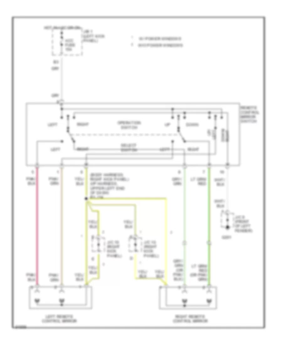
Power Mirror Wiring Diagram for Toyota 4Runner Limited 1996
List of elements for Power Mirror Wiring Diagram for Toyota 4Runner Limited 1996:
- (body harness, right kick panel) (i/p harness, upper left end of dash) b1, i14
- Acc fuse 15a
- Down
- Down/ right
- G201
- Hot in acc or on
- J/b 1 (left kick panel)
- J/c 10 (right kick panel)
- J/c 9 (front of left fender)
- Left
- Left remote control mirror
- Operation switch
- Remote control mirror switch
- Right
- Right remote control mirror
- Select switch
- Up/ left
- W/ power windows
- W/o power windows
POWER SEATS
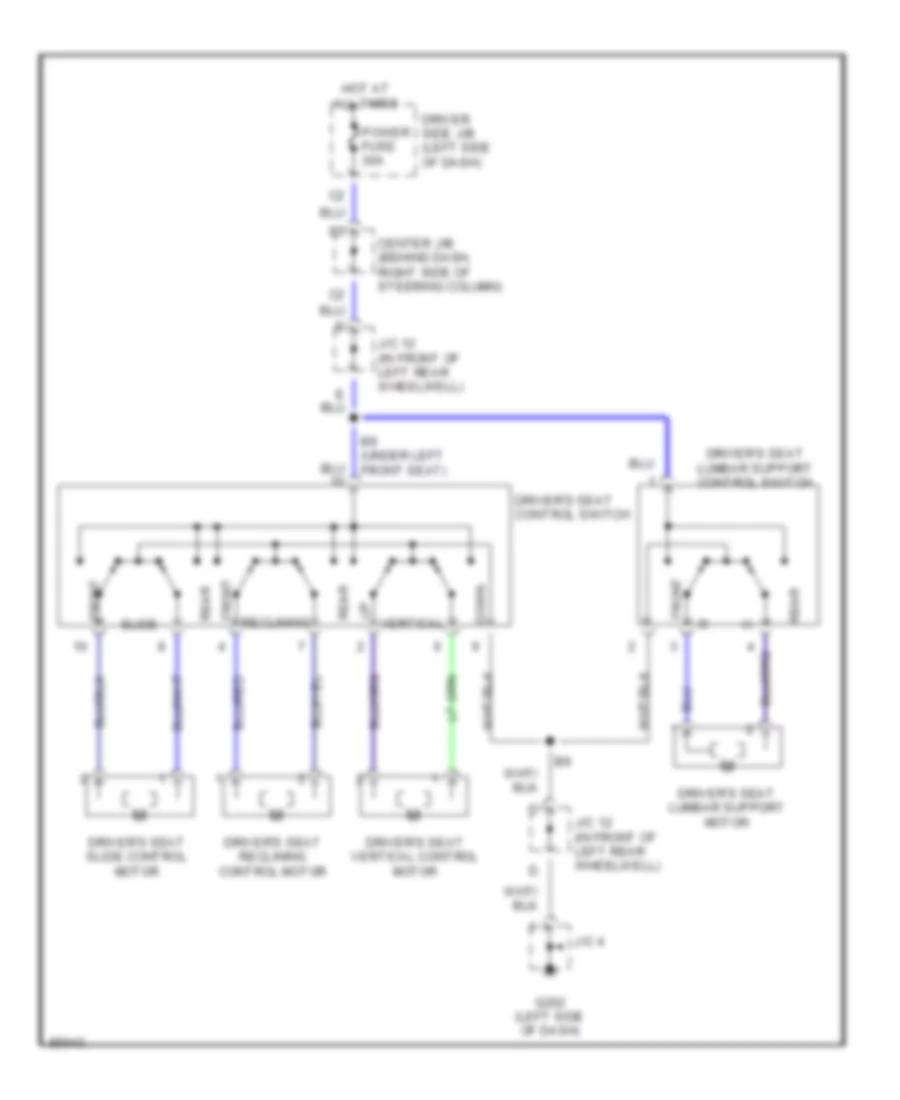
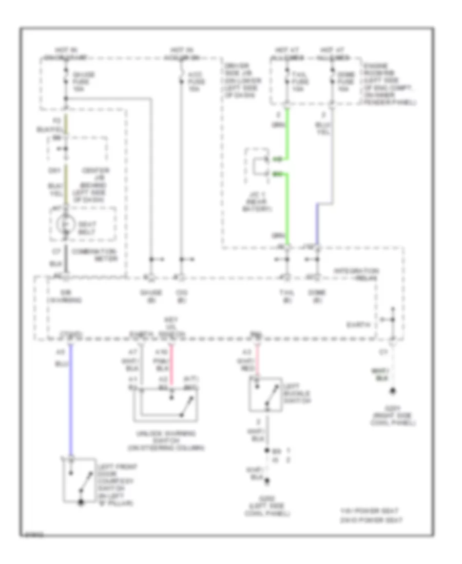
Driver Power Seat Wiring Diagram for Toyota 4Runner Limited 1996
List of elements for Driver Power Seat Wiring Diagram for Toyota 4Runner Limited 1996:
- B9 (under left front seat)
- Center j/b (behind dash, right side of steering column)
- Down
- Driver side j/b (left side of dash)
- Driver's seat control switch
- Driver's seat lumbar support control switch
- Driver's seat lumbar support motor
- Driver's seat reclining control motor
- Driver's seat slide control motor
- Driver's seat vertical control motor
- Front
- G202 (left side of dash)
- Hot at all times
- J/c 12 (in front of left rear wheelwell)
- J/c 4
- Power fuse 30a
- Rear
- Reclining
- Slide
- Vertical
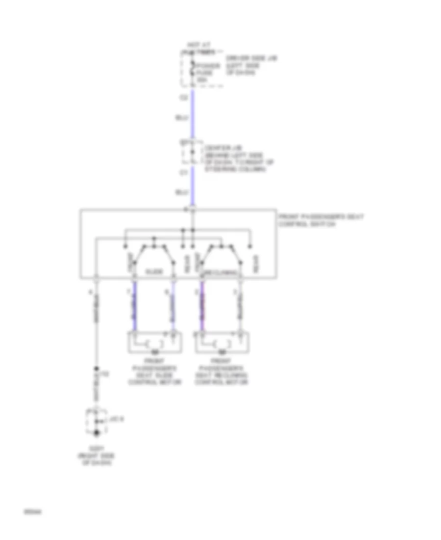
Passenger Power Seat Wiring Diagram for Toyota 4Runner Limited 1996
List of elements for Passenger Power Seat Wiring Diagram for Toyota 4Runner Limited 1996:
- Center j/b (behind left side of dash, to right of steering column)
- Driver side j/b (left side of dash)
- Front
- Front passenger's seat control switch
- Front passenger's seat reclining control motor
- Front passenger's seat slide control motor
- G201 (right side of dash)
- Hot at all times
- J/c 9
- Power fuse 30a
- Rear
- Reclining
- Slide
POWER TOP/SUNROOF
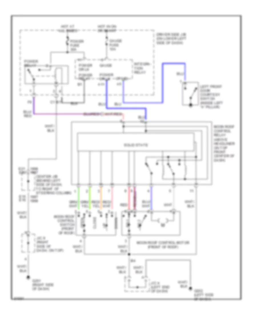
Power Top/Sunroof Wiring Diagrams for Toyota 4Runner Limited 1996
List of elements for Power Top/Sunroof Wiring Diagrams for Toyota 4Runner Limited 1996:
- (above headliner on top front center of dash)
- A11
- Center j/b (behind left side of dash, to right of steering column)
- Close
- Cty(d)
- Down
- Driver side j/b (on lower left side of dash)
- E15
- E16
- E21 e20
- G201 (right side of dash)
- G202 (left side of dash)
- Gauge
- Gauge fuse 10a
- Hot at all times
- Hot in on or start
- Integra- tion relay
- J/c 4 (left end of dash)
- J/c 9 (right side of dash, on top)
- Left front door courtesy switch (inside left "a" pillar)
- Moon roof control motor (front of roof)
- Moon roof control relay
- Moon roof control switch (front of roof)
- No.1
- No.2
- Open
- Power dr lk
- Power fuse 30a
- Power relay
- Red
- Solid state
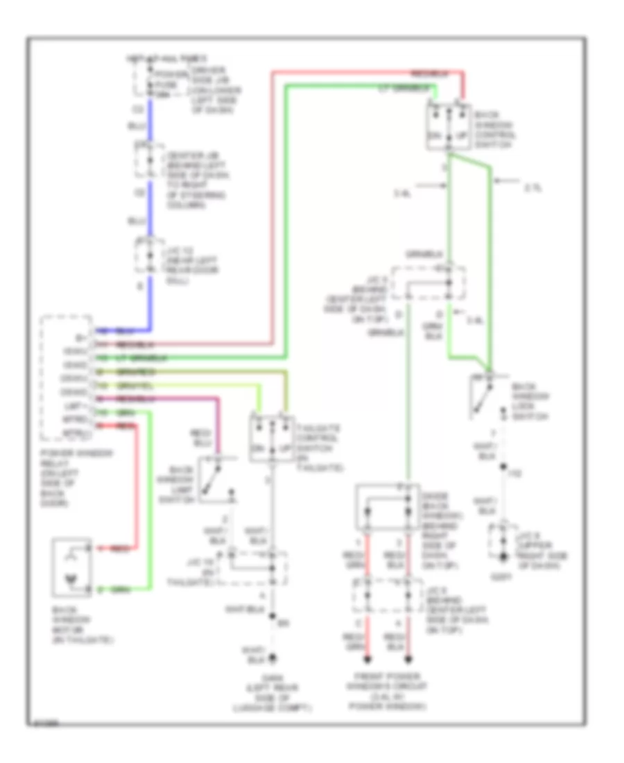
POWER WINDOWS
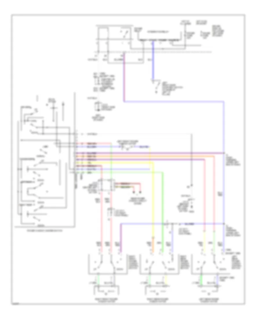
Power Window Wiring Diagram, Front for Toyota 4Runner Limited 1996
List of elements for Power Window Wiring Diagram, Front for Toyota 4Runner Limited 1996:
- (1998)
- (1998) e21
- (except 1998)
- (except 1998) e20
- Center j/b (to right steering column)
- Cty (d)
- Down
- Driver side j/b (on lower left side of dash)
- Driver's
- E15 (except 1998) (1998) e16
- G201 (right side of dash)
- G202
- Gauge (b)
- Gauge fuse 10a
- Hot at all times
- Hot in on or start
- I2 (dash harness, upper left end of dash)
- Integration relay
- J/c 10/11 (at right kick panel)
- J/c 4 (behind left side of dash, on top)
- J/c 6 (behind center left of dash, on top)
- J/c 9 (right side of dash)
- Left front door courtesy switch (at base of left "a" pillar)
- Left front power window motor
- Left rear
- Left rear power window control switch
- Left rear power window motor
- Lock
- Normal
- Passenger's
- Power
- Power fuse 30a
- Power relay
- Power window master switch
- Rear power window circuit (diode)
- Relay
- Right front power window control switch
- Right front power window motor
- Right rear
- Right rear power window control switch
- Right rear power window motor
- Solid state
Power Window Wiring Diagram, Rear for Toyota 4Runner Limited 1996
List of elements for Power Window Wiring Diagram, Rear for Toyota 4Runner Limited 1996:
- 2.7l
- 3.4l
- Back window control switch
- Back window limit switch
- Back window lock switch
- Back window motor (in tailgate)
- Center j/b (behind left side of dash, to right of steering column)
- Diode (back window) (behind right side of dash, on top)
- Driver side j/b (on lower left side of dash)
- Front power windows circuit (3.4l w/ power window)
- G201
- G404 (left rear side of luggage compt)
- Hot at all times
- I12
- Iswd
- Iswu
- J/c 12 (near left rear door sill)
- J/c 16 (in tailgate)
- J/c 5 (behind center left side of dash, on top)
- J/c 6 (behind center left side of dash, on top)
- J/c 9 (upper right side of dash)
- Lmt+
- Mtrd
- Mtru
- Oswd
- Oswu
- Power fuse 30a
- Power window relay (on left side of back door)
- Red
- Tailgate control switch (in tailgate)
RADIO
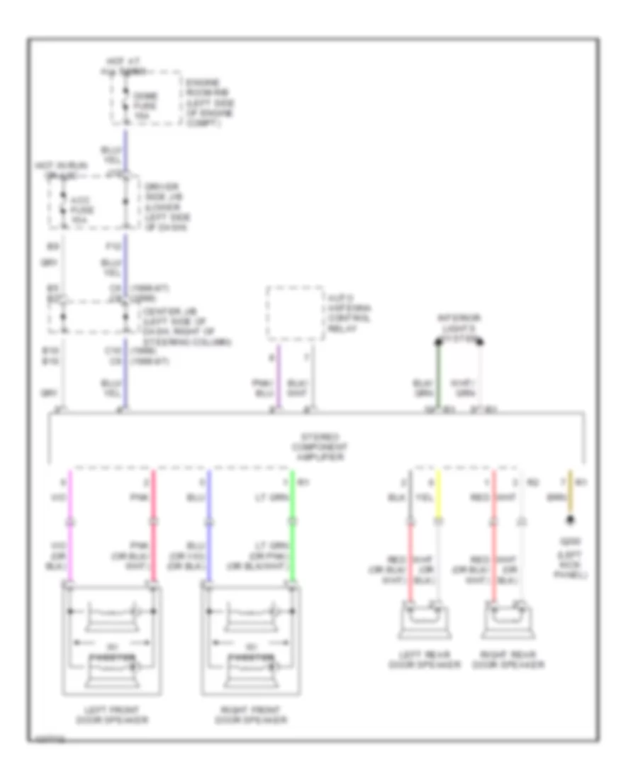
Radio Wiring Diagrams for Toyota 4Runner Limited 1996
List of elements for Radio Wiring Diagrams for Toyota 4Runner Limited 1996:
- (1996-97)
- (1996-97) c6 c8
- (1998)
- (1998) c10 c9
- (left kick panel)
- Acc fuse 15a
- Auto antenna control relay
- B10 b10
- B5 b7
- Center j/b (left side of dash, right of steering column)
- Dome fuse 15a
- Driver side j/b (lower left side of dash)
- Engine room r/b (left side of engine compt)
- F12
- G200
- Hot at all times
- Hot in run or acc
- Interior lights system
- J12
- Left front door speaker
- Left rear door speaker
- Pnk
- Red
- Right front door speaker
- Right rear door speaker
- Stereo component amplifier
- W/ tweeter
SHIFT INTERLOCKS
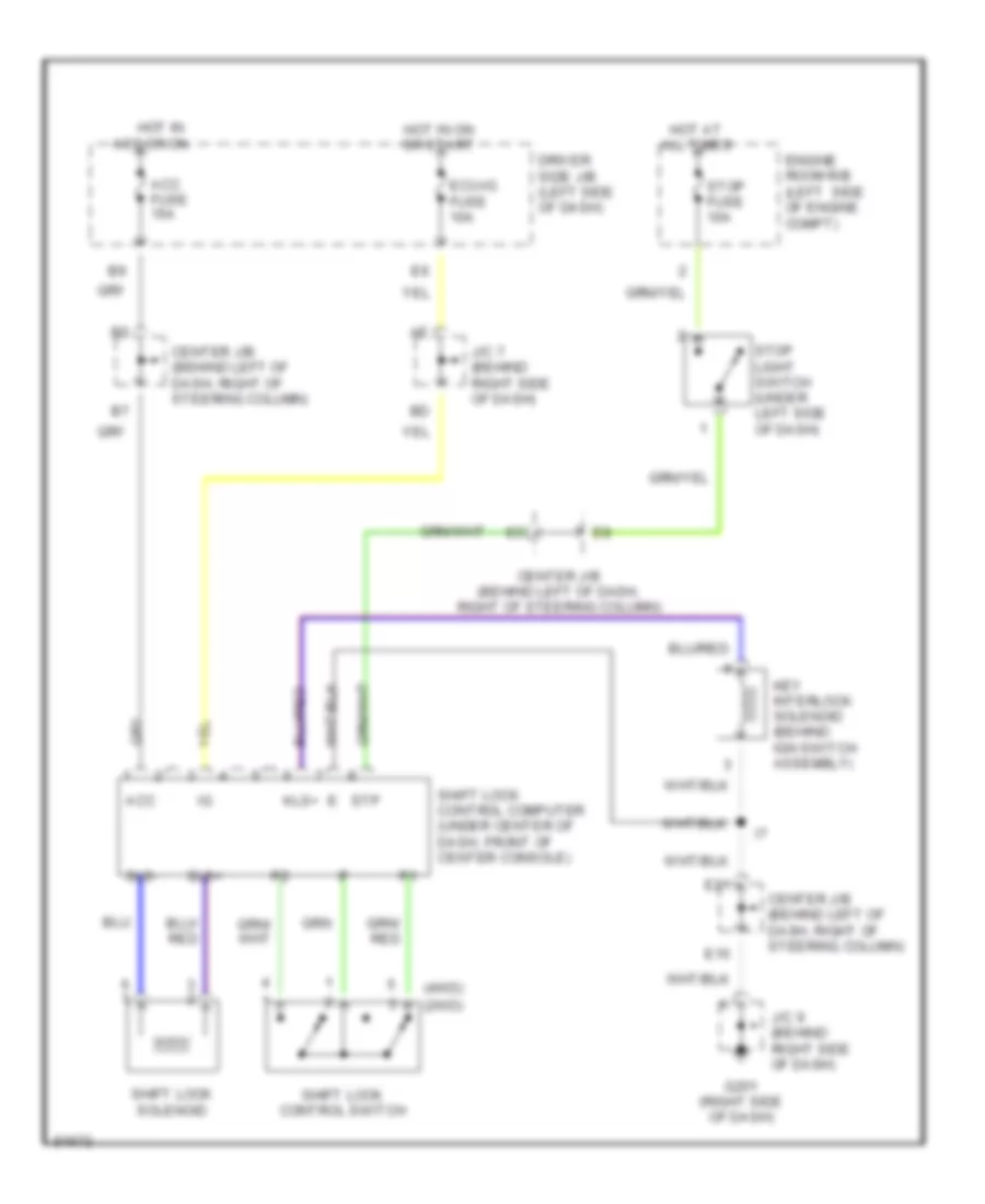
Shift Interlock Wiring Diagram for Toyota 4Runner Limited 1996
List of elements for Shift Interlock Wiring Diagram for Toyota 4Runner Limited 1996:
- (2wd)
- (4wd)
- Acc
- Acc fuse 15a
- Center j/b (behind left of dash, right of steering column)
- Driver side j/b (left side of dash)
- E15
- E21
- Ecu-ig fuse 10a
- Engine room r/b (left side of engine compt)
- G201 (right side of dash)
- Hot at all times
- Hot in acc or on
- Hot in on or start
- J/c 7 (behind right side of dash)
- J/c 9 (behind right side of dash)
- Key interlock solenoid (behind ign switch assembly)
- Kls+
- Shift lock control computer (under center of dash, front of center console)
- Shift lock control switch
- Shift lock solenoid
- Sls+
- Sls-
- Stop fuse 10a
- Stop light switch (under left side of dash)
- Stp
STARTING/CHARGING
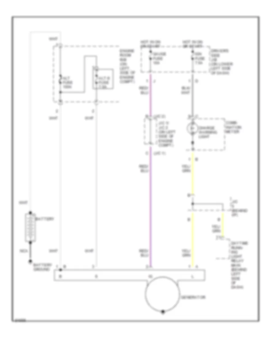
Charging Wiring Diagram for Toyota 4Runner Limited 1996
List of elements for Charging Wiring Diagram for Toyota 4Runner Limited 1996:
- (j/c 1)
- (j/c 2)
- Alt fuse 100a
- Alt-s fuse 7.5a
- Battery
- Battery ground
- Charge warning light
- Comb- ination meter
- Daytime runn- ing light relay main (behind left side of dash)
- Driver's side j/b (on lower left side of dash)
- Engine room r/b (on left, side of engine compt)
- Gauge fuse 10a
- Generator
- Hot in on or start
- Ign fuse 7.5a
- J/c (behind i/p)
- J/c 1/ j/c 2 (on left side of engine compt)
- Nca
Starting Wiring Diagram for Toyota 4Runner Limited 1996
List of elements for Starting Wiring Diagram for Toyota 4Runner Limited 1996:
- (3.4l) (2.7l)
- (left front fender apron, engine harness) e3
- A/t only
- Acc
- Alt fuse 100a
- Am1 fuse 40a
- Am2 fuse 30a
- Battery
- Battery ground
- Center j/b (behind left side of dash)
- Clutch start cancel switch (m/t)
- Clutch start switch (m/t) (under left side of dash)
- Driver's side j/b (on lower left side of dash)
- E10 e9
- Engine control module (behind right side of dash)
- Engine room r/b (left side of engine compt)
- G201 (right side of cowl panel)
- Gauge fuse 10a
- I2 (i/p harness, left kick panel)
- I3 (i/p harness, behind driver's side j/b)
- I4 (i/p harness, upper left end of dash)
- Ignition switch
- J/c (behind right end of dash)
- M/t only
- Nca
- Nsw
- Off
- P/ n
- Park/ neutral position switch (a/t) (on trans- mission)
- Start
- Starter
- Starter relay
SUPPLEMENTAL RESTRAINTS
Supplemental Restraint Wiring Diagram for Toyota 4Runner Limited 1996
List of elements for Supplemental Restraint Wiring Diagram for Toyota 4Runner Limited 1996:
- Acc
- Acc fuse 15a
- Airbag sensor assembly (behind lower center of dash)
- Airbag squib (front passenger's airbag assembly)
- Airbag squib (steering wheel pad)
- B11
- Combination meter
- Data link connector 1 (left side of engine compt)
- Driver side j/b (lower left side of dash)
- Ecu-b fuse 7.5a
- G200 (left kick panel)
- G203 (right kick panel)
- Hot at all times
- Hot in on or accy
- Hot in on or start
- Ig2
- Ign fuse 7.5a
- J/c 3 (left side of dash)
- Srs warning ind
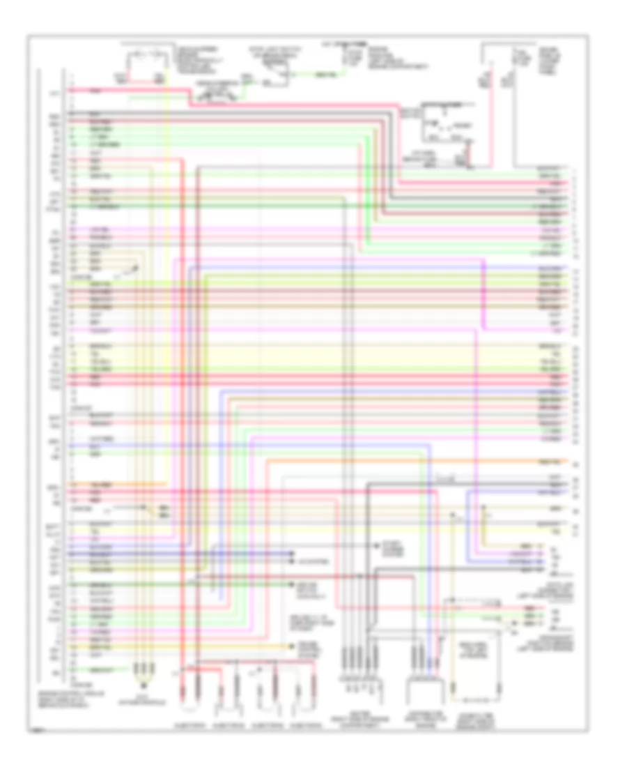
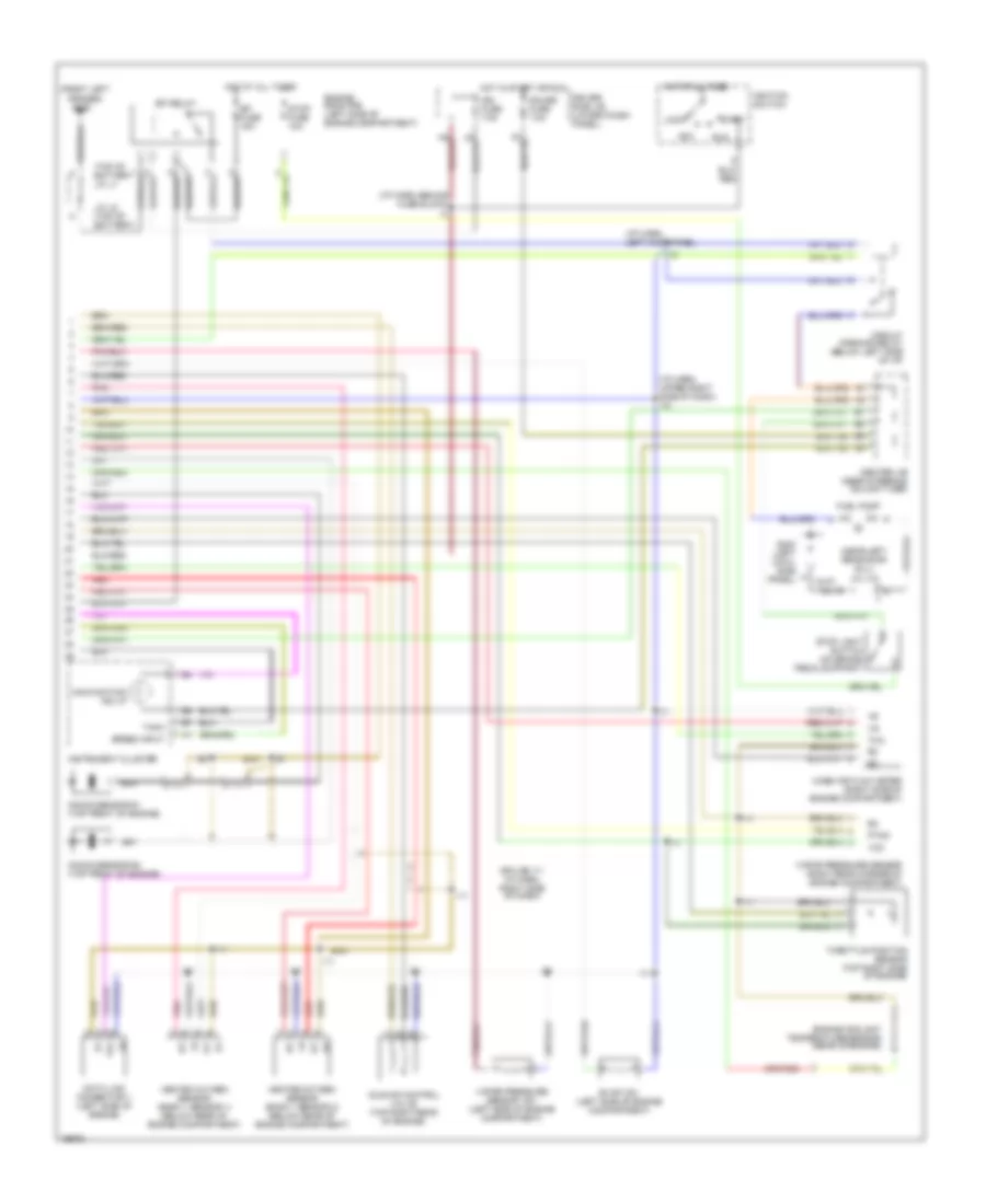
TRANSMISSION
Rear Differential Lock Wiring Diagram for Toyota 4Runner Limited 1996
List of elements for Rear Differential Lock Wiring Diagram for Toyota 4Runner Limited 1996:
- (top right side of i/p)
- 2.7l 3.4l
- 4wd
- 4wd control ecu (left kick panel)
- 4wd ecu (left kick panel)
- 4wd fuse 20a
- A17
- Abs ecu (right kick panel)
- C10
- C12
- C16
- E14
- E15
- E17
- Engine control module (w/ a/t only) (right side of i/p)
- Free
- G201
- G202
- Gauge fuse 10a
- Gnd
- Hot in on or start
- I10 (w/o 2-4 switch) i1 (w/ 2-4 switch) (i10: i/p harn, upper right side of dash) (i1: i/p harn, left kick panel)
- I11 (i/p harn, right side of dash)
- I12
- Instrument cluster
- J/b 1 (left side of i/p, on lower finish panel)
- J/b 3 (near steering column)
- J/c 12 (under left rear seat)
- J/c 13
- J/c 4 (left cowl panel)
- J/c 7
- J/c 8
- J/c 9 (right cowl panel)
- Limit switch
- Lock
- Rear differential lock control switch
- Rear differential lock detection switch
- Rear differential lock indicator
- Rear differential lock motor
- Rel1
- Rel2
- Rlp
- Rly1
- Rly2
- Spd
- Speedometer
- Transfer l4 position detection switch
- W/ 2-4 select switch
Transfer Case Wiring Diagram, with 2-4 Select Switch for Toyota 4Runner Limited 1996
List of elements for Transfer Case Wiring Diagram, with 2-4 Select Switch for Toyota 4Runner Limited 1996:
- (i/p harness, left kick panel) i1
- (i/p harness, right side of i/p)
- (i/p harness, right side of i/p) i11
- (left front fender)
- 2-4
- 2-4 select motor (center rear of engine compt)
- 2-4 select switch
- 4wd
- 4wd control ecu (left kick panel)
- 4wd ecu (left kick panel)
- 4wd fuse 20a
- 4wd indicator
- A/t indicator switch
- A/t parking indicator
- A17
- Abs ecu (center of i/p)
- Add indicator switch (differential)
- C10
- C12
- C13
- E12
- E14
- E15
- Engine control module (right side of i/p)
- Exi
- G100
- G200 (left kick panel)
- Gauge fuse 10a
- Grd
- Hot in on or start
- I10 (i/p harness, upper right side of i/p)
- I11
- I11 (i/p harn, right side of i/p)
- I5 (i/p harness, upper left side of i/p)
- Ind
- Instrument cluster
- J/b 1 (left kick panel)
- J/b 3 (near steering column tube)
- J/c 1 (left front of engine compt)
- J/c 2
- J/c 7
- J/c 7 (right side of i/p)
- J/c 8
- J/c 8 (right side of i/p)
- Park/neutral position switch
- Pnk
- Rl1
- Rl2
- Spd
- Speedometer
- Tfn
- Transfer 4wd position detection switch (transfer case)
- Transfer l4 position detection switch (transfer case)
- Transfer neutral position detection switch (transfer case)
- Vsv 2 (2wd, add) (left front of eng compt)
- Vsv 4 (4wd, add) (left front of eng compt)
Transfer Case Wiring Diagram, without 2-4 Select Switch for Toyota 4Runner Limited 1996
List of elements for Transfer Case Wiring Diagram, without 2-4 Select Switch for Toyota 4Runner Limited 1996:
- (a/t) (transfer case)
- (behind battery)
- (i/p harn, right side of dash)
- (i/p harn, upper right side of dash)
- (right kick panel)
- (upper right corner of dash)
- 2.7l a/t
- 2.7l m/t
- 3.4l a/t
- 3.4l m/t
- 4wd
- 4wd fuse 20a
- 4wd ind
- A11
- A12
- Abs ecu
- Add control relay (lower right side of dash)
- Add indicator switch (front differential)
- Center j/b (near steering column)
- Dectection switch (transfer 4wd pos) (transfer case)
- Dectection switch (transfer l4 pos) (transfer case)
- Detection switch (transfer neutral position)
- Diff lock ecu (left kick panel)
- Driver side j/b (lower finish panel)
- E12
- Engine control module (right side of dash)
- Exi
- G101 (front left fender)
- G203 (right cowl side panel)
- Gauge fuse 10a
- Hot in on or start
- I10
- I11
- Instrument cluster
- J/c j1
- J/c j2
- J/c j7
- J/c j7 (upper right corner of dash) j/c j8
- J/c j8
- Nca
- Park/ neutral position switch (a/t) (transmission)
- Parking ind (a/t)
- Short pin (w/o add)
- Tfn
- Vsv (2wd, add)
- Vsv (4wd, add)
- W/ rear diff lock
Transmission Wiring Diagram for Toyota 4Runner Limited 1996
List of elements for Transmission Wiring Diagram for Toyota 4Runner Limited 1996:
- (2.7l only)
- (right side of dash)
- (right side of dash) i11
- (right side of transmission) park/neutral position switch
- 2.7l
- 3.4l
- A/t prk indic
- A10
- A13
- A21
- A24
- A25
- A26
- B10
- B11
- Batt
- C10
- Cruise control
- D12
- D13
- D14
- D15
- D16
- D17
- D18
- D21
- E11
- E17
- E27
- E33
- E34
- Ect pwr indic
- Efi
- Efi fuse 15a
- Electronic controlled transmission solenoid
- Engine control module (right kick panel)
- Engine coolant
- Eo1
- Eo2
- Eo3
- F12
- F20
- F22
- G100 (left front fender)
- G16
- G203 (right kick panel)
- Guage fuse 10a
- H10
- H12
- H14
- H17
- H22
- H25
- Hot at all times
- Hot in on or start
- I11
- I11 (right side dash)
- Idl
- Ign fuse 7.5a
- Instrument cluster
- J/b 1 (left kick panel)
- J/b 3 (left side of dash)
- J/c (near battery)
- J/c 6 (center of dash)
- Neutral detection switch (on transfer case)
- No.
- O/d main switch (below center console)
- O/d off indic
- Od1
- Od2
- Oil
- Oil temp indic
- Oil-w
- Pwr
- R/b 2 (left engine compt)
- Relay
- Sol
- Sp1
- Sp2+
- Sp2-
- Speedo- meter
- Starting/ charging
- Stop fuse 10a
- Stop light switch (above brake pedal)
- Temperature sensor (rear of engine)
- Tfn
- Throttle position sensor (on throttle body)
- Thw
- Transmission fluid temperature switch (on trans)
- Transmission pattern select switch (center console)
- Vcc
- Vehicle speed sensor (on trans)
- Vta
WARNING SYSTEMS
Warning System Wiring Diagrams for Toyota 4Runner Limited 1996
List of elements for Warning System Wiring Diagrams for Toyota 4Runner Limited 1996:
- (a/t)
- (behind
- (m/t)
- A10
- Acc fuse 15a
- Bkl
- Center
- Cig (b)
- Combination
- Cty(d)
- D61
- Dome (b)
- Dome fuse 10a
- Driver side j/b (on lower left side of dash)
- Earth
- Engine room r/b (left side of eng compt, on inner fender panel)
- G201 (right side cowl panel)
- G202 (left side cowl panel)
- Gauge (b)
- Gauge fuse 10a
- Hot at all times
- Hot in acc or on
- Hot in on or start
- Integration
- J/b
- J/c 1 (near batery)
- J12
- Key u/l switch
- Left buckle switch
- Left front door courtesy switch (in left "b" pillar)
- Left side of dash)
- Meter
- Relay
- S/b warning
- Seat belt
- Tail (b)
- Tail fuse 10a
- Unlock warning switch (on steering column)
- W/ power seat
- W/o power seat
WIPER/WASHER
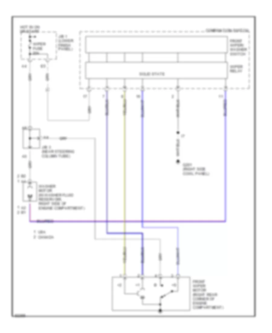
Front Wiper/Washer Wiring Diagram for Toyota 4Runner Limited 1996
List of elements for Front Wiper/Washer Wiring Diagram for Toyota 4Runner Limited 1996:
- A2 b1
- Canada
- Combination switch
- Front wiper motor (right rear corner of engine compartment)
- Front wiper/ washer switch
- G201 (right side cowl panel)
- Hot in on or start
- J/b 1 (lower finish panel)
- J/b 3 (near steering column tube)
- Solid state
- Usa
- Washer motor (in washer fluid reservoir, right side of engine compartment)
- Wiper fuse 20a
- Wiper relay
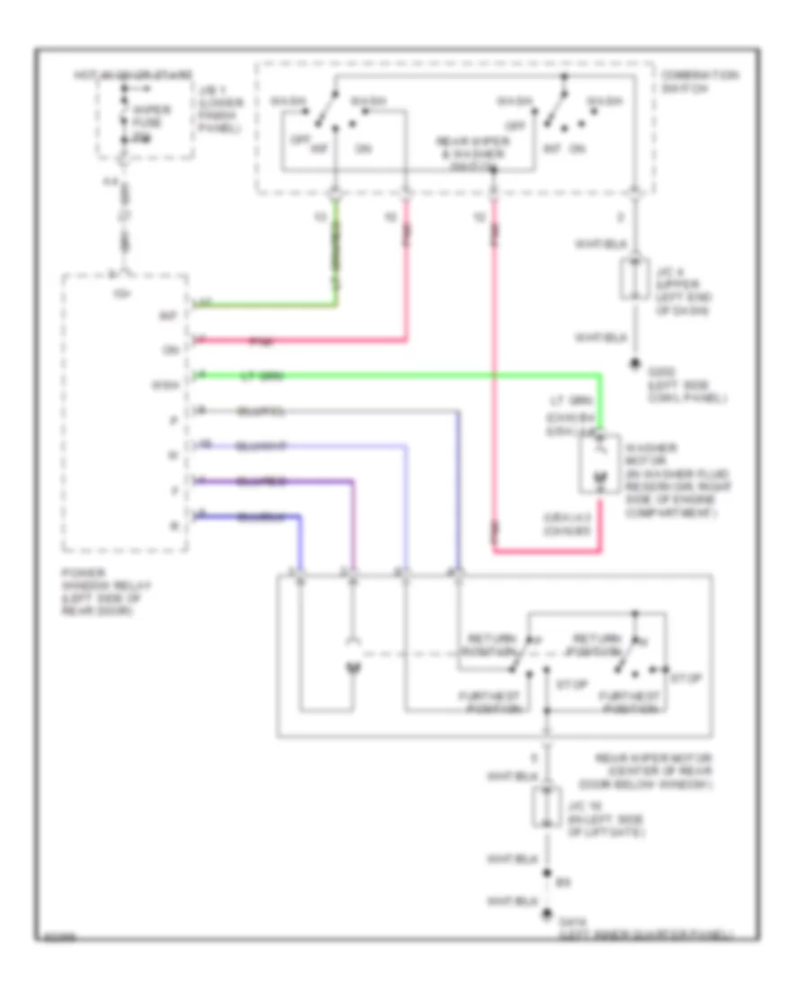
Rear Wiper/Washer Wiring Diagram for Toyota 4Runner Limited 1996
List of elements for Rear Wiper/Washer Wiring Diagram for Toyota 4Runner Limited 1996:
- (can) (usa)
- (usa) (can)
- A3 b5
- B4 a4
- Combination switch
- Furthest position
- G202 (left side cowl panel)
- G414 (left inner quarter panel)
- Hot in on or start
- Ig+
- Int
- J/b 1 (lower finish panel)
- J/c 16 (in left side of liftgate)
- J/c 4 (upper left end of dash)
- Off
- On int
- Pnk
- Power window relay (left side of rear door)
- Rear wiper & washer switch
- Rear wiper motor (center of rear door below window)
- Return position
- Stop
- Wash
- Washer motor (in washer fluid reservoir, right side of engine compartment)
- Wiper fuse 20a
- Wsh

 Čeština
 Dansk
Dansk Deutsch
 Ελληνικά
 English
 English
 Español
 Suomi
Suomi Français
 Français
 עברית
עברית Hrvatski
 Magyar
 Italiano
 日本語
日本語 한국어
한국어 Nederlands
 Polski
 Português
 Português
 Română
 Slovenčina
 Slovenščina
 Svenska
 Türkçe
 中文 (中国)