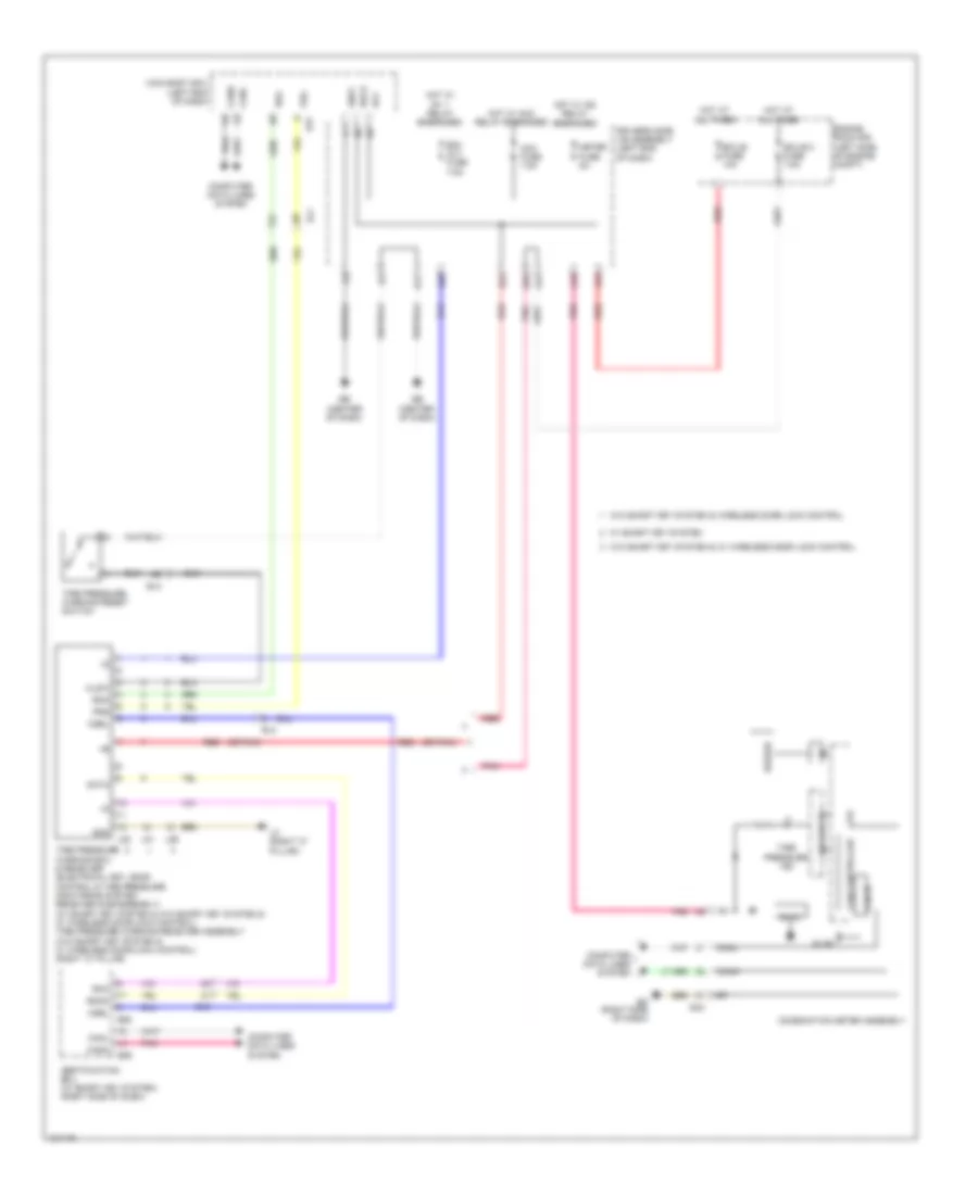
AIR CONDITIONING
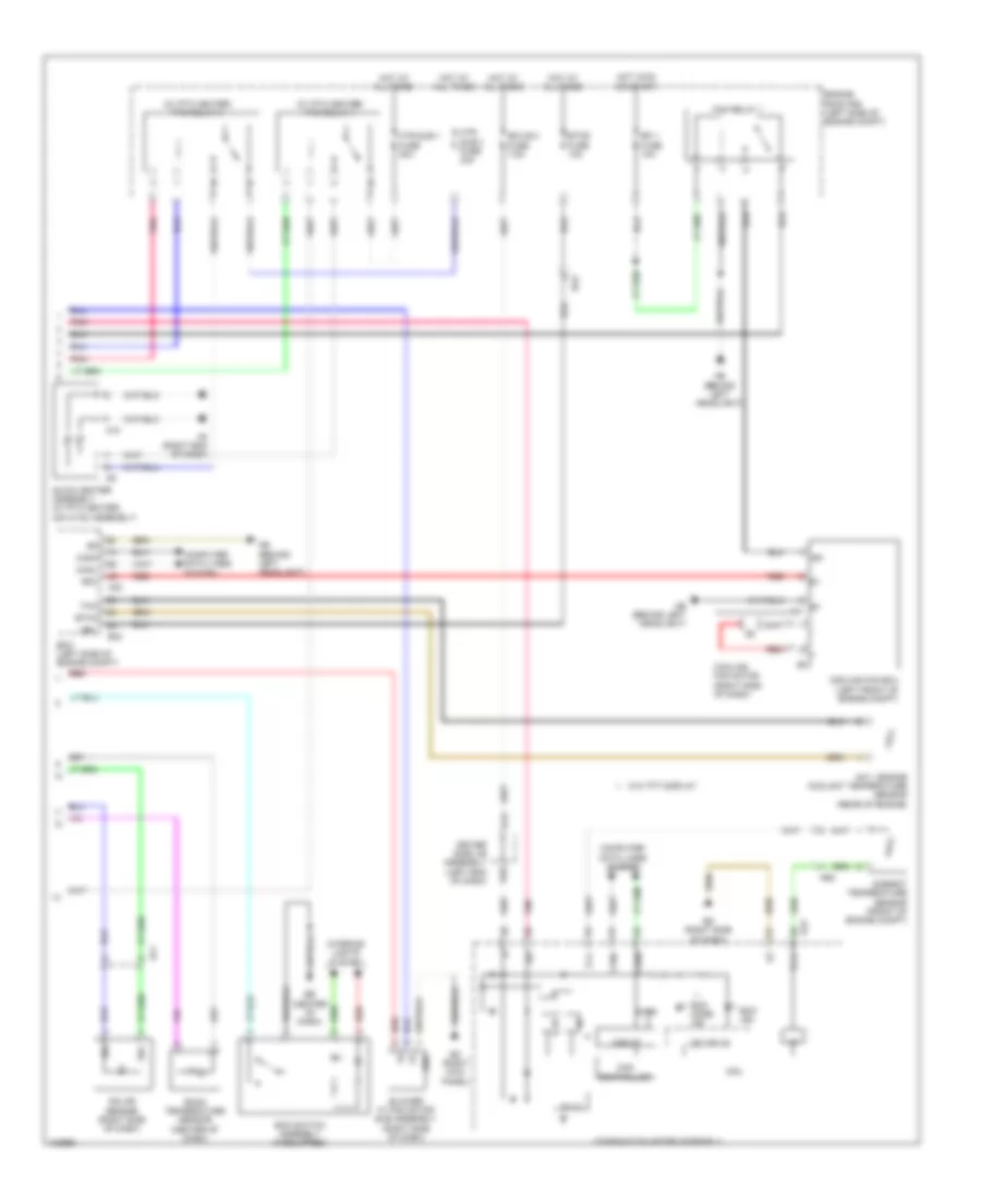
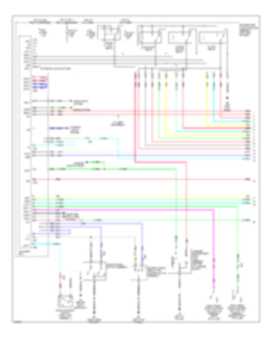
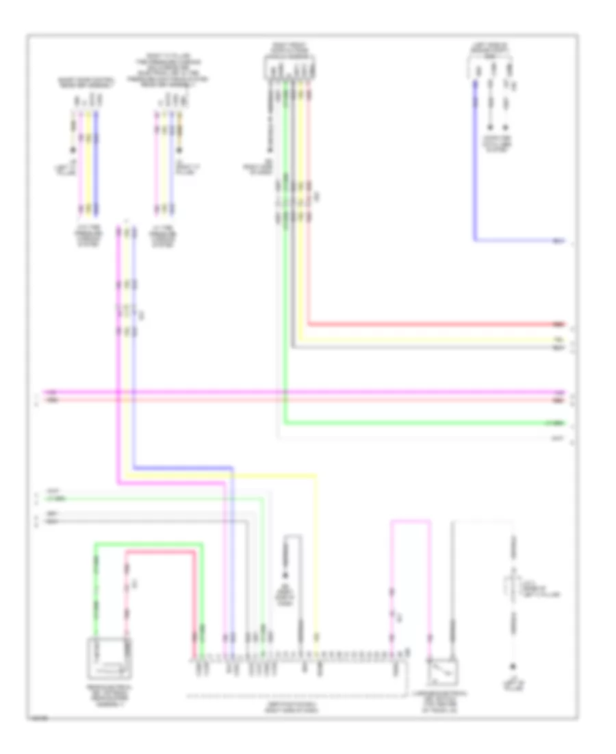
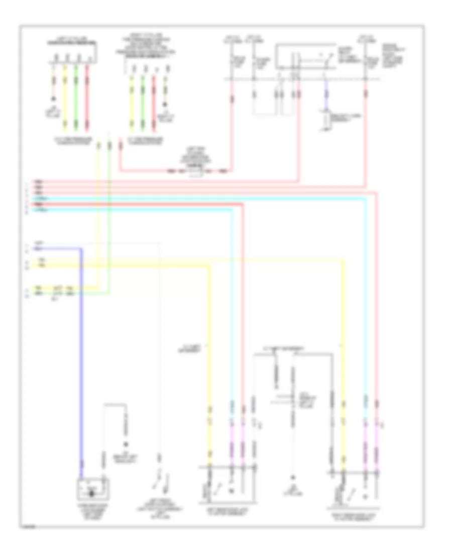
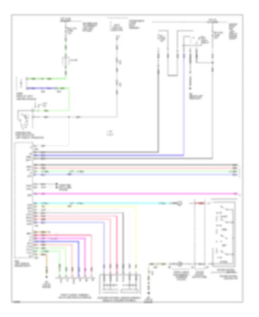
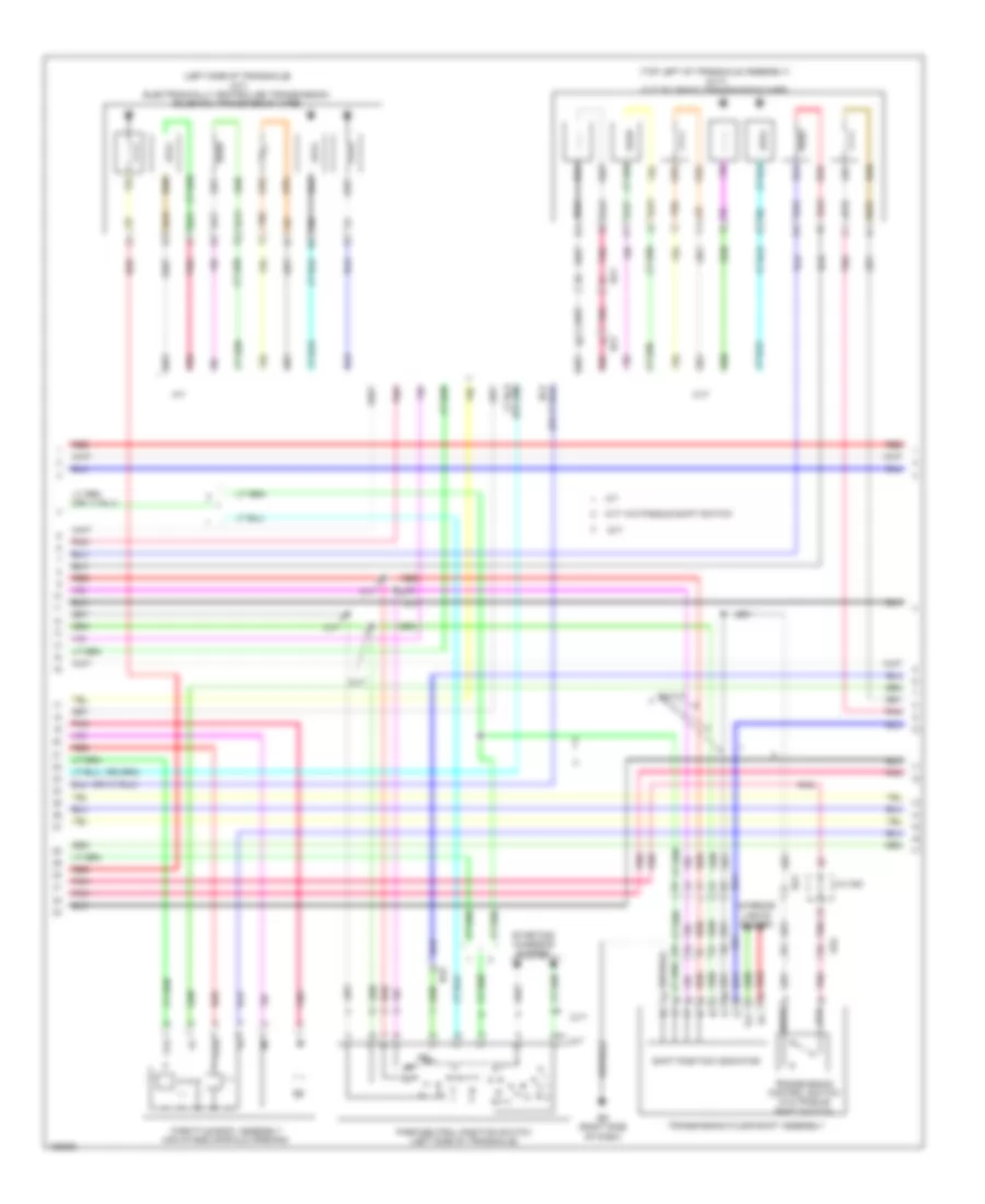
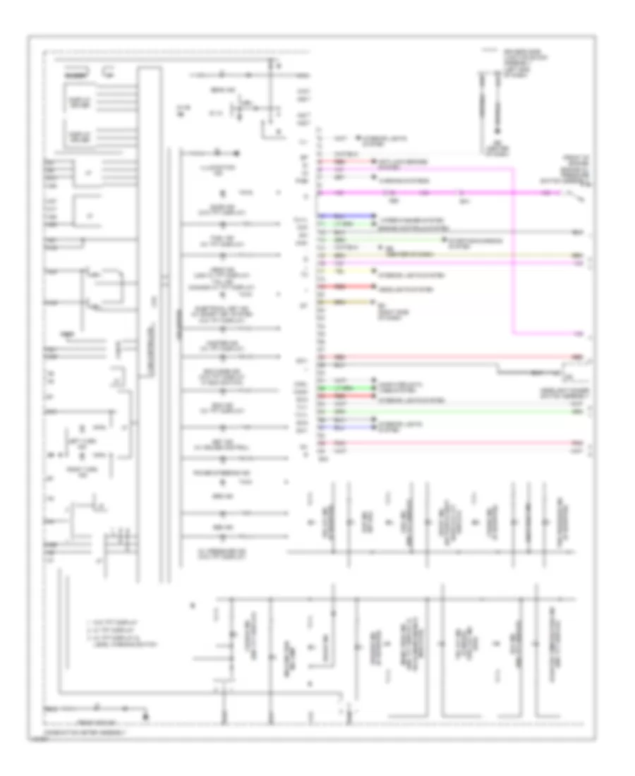
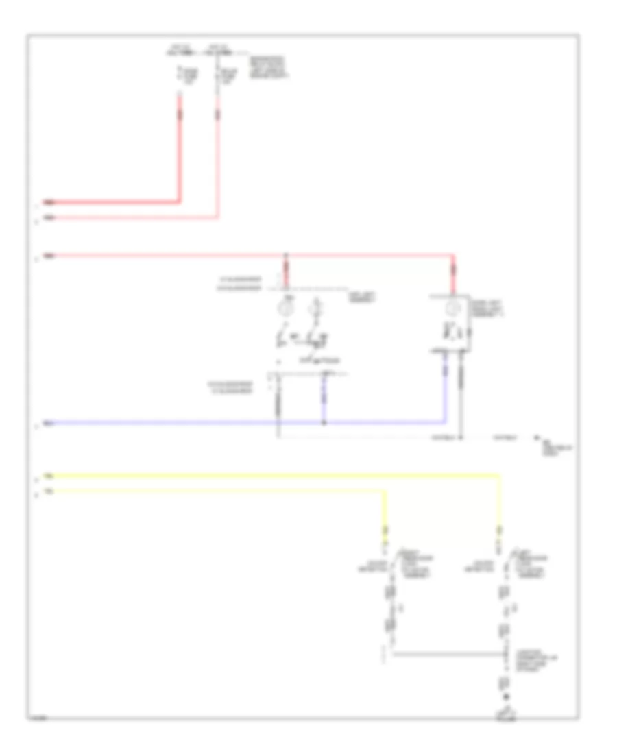
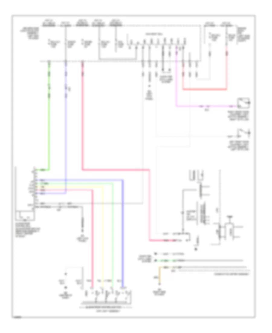
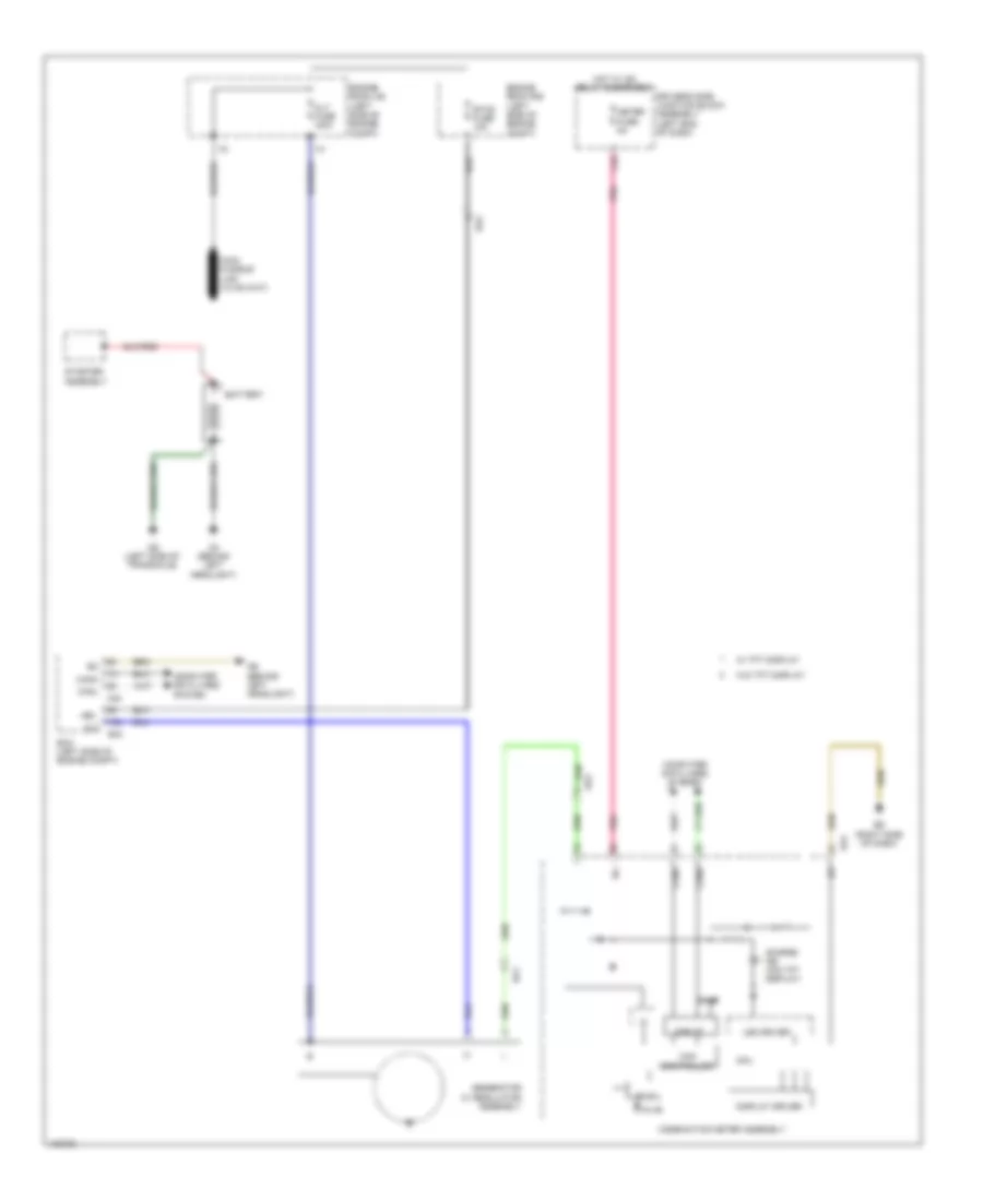
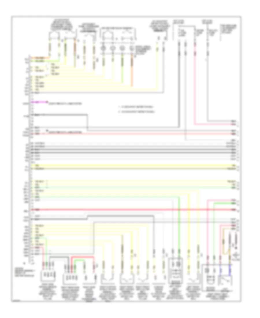
Automatic A/C Wiring Diagram (1 of 2) for Toyota Corolla LE Eco 2014
 https://portal-diagnostov.com/license.html
Automotive Electricians Portal FZCO
Automotive Electricians Portal FZCO
https://portal-diagnostov.com/license.html
https://portal-diagnostov.com/license.html
Automotive Electricians Portal FZCO
Automotive Electricians Portal FZCO
List of elements for Automatic A/C Wiring Diagram (1 of 2) for Toyota Corolla LE Eco 2014:
- (right side of dash) ed
- (top of engine) bb
- (w/ valvematic) mgc relay
- A/c amplifier assembly (center of dash)
- A/c blower assembly (a/c harness assembly) (center of dash)
- A/c control assembly
- A/c evaporator temperature sensor
- A/c pressure sensor (right front of
- A23
- A25
- A26
- A44
- A47
- Ae1
- Ae6
- B bus
- B36
- Ba1
- Ba2
- Blw
- Bus
- Bus g
- C55
- Canh
- Canl
- Compressor w/ pulley assembly (left front of engine)
- Computer data lines system
- Connector housing color (black)
- Connector housing color (red)
- D42
- D45
- Damper servo motor (air mix)
- Damper servo motor (fresh/recirculation)
- Damper servo motor (mode control)
- Defogger system
- Driver side j/b assembly (left end of dash)
- E37
- Eb (center of dash)
- Ecos
- Ecu-b2 fuse 7.5a
- Engine compt)
- Engine room r/b (left side of engine compt)
- Gnd
- Hot at all times
- Hot in on or start
- Htr fuse 50a
- Htr-ig fuse 10a
- Ig+
- Ill+
- Ill-
- Interior lights system
- J/c a38
- Lin1
- Lock
- Meter fuse 5a
- Mg+
- Mgc
- Pnk
- Pre
- Ptc1
- Ptc2
- Rdfg
- Rdi fuse 30a
- Rear window defogger switch
- Red
- S5-1
- S5-3
- Sg-1
- Sg-2
- Sga
- Sol+
- Sol-
- Ssr+
- Ssr-
- Tea
- Tsd
- W/ dual vvt-i
- W/ valvematic
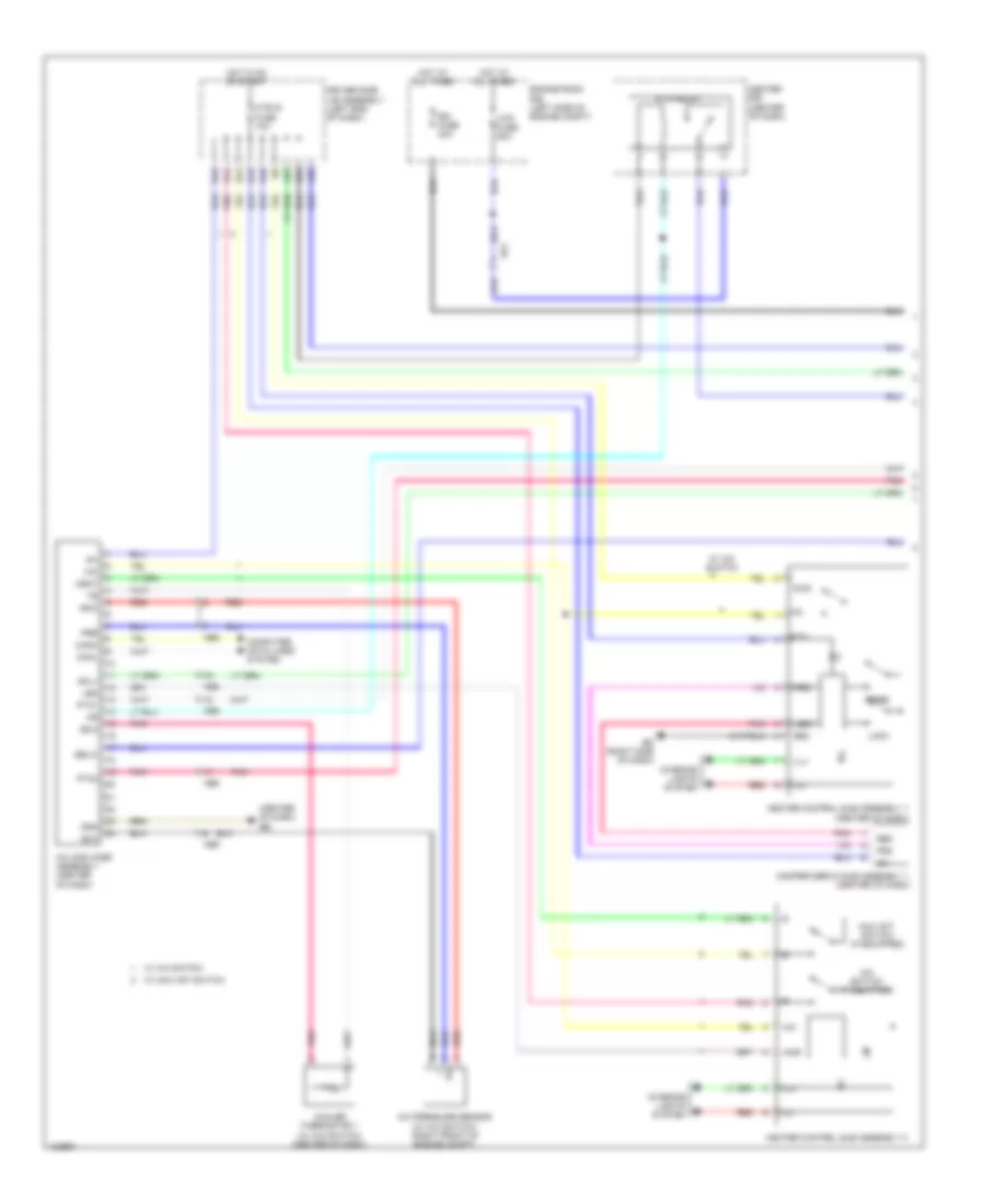
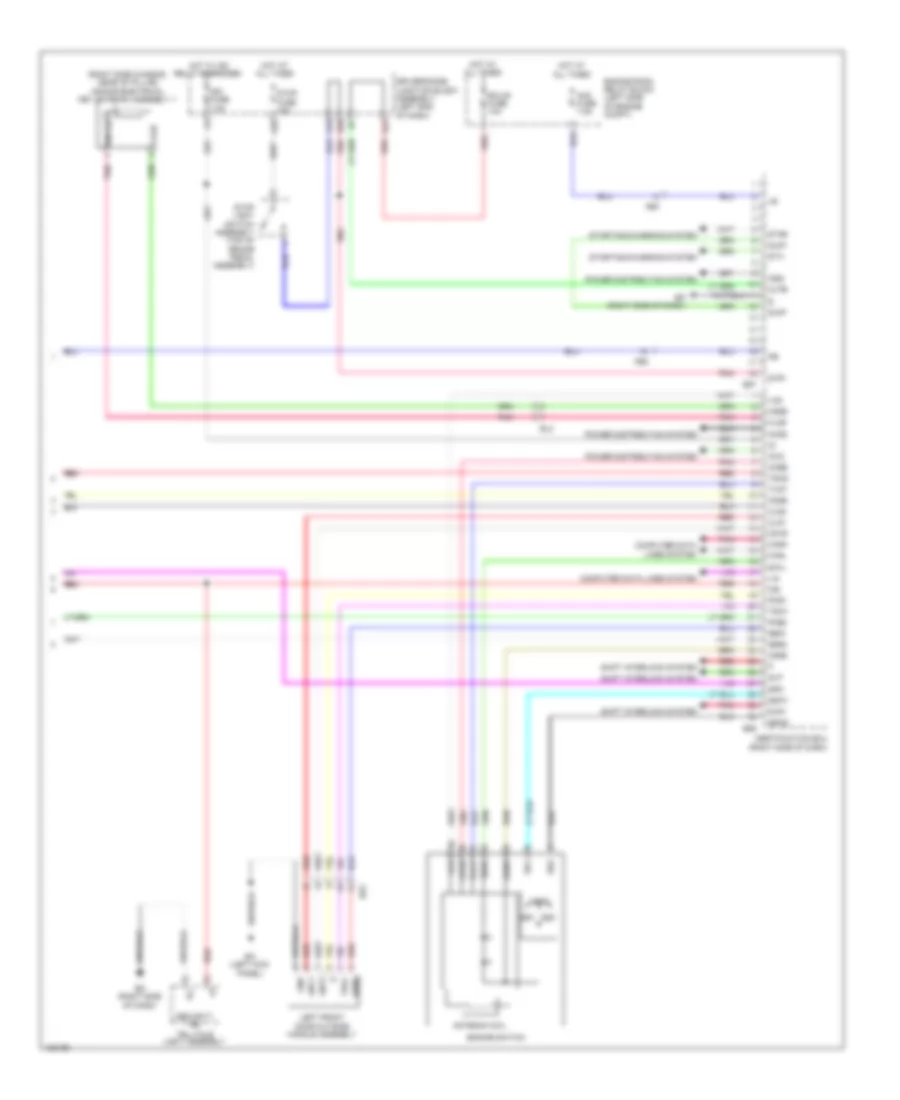
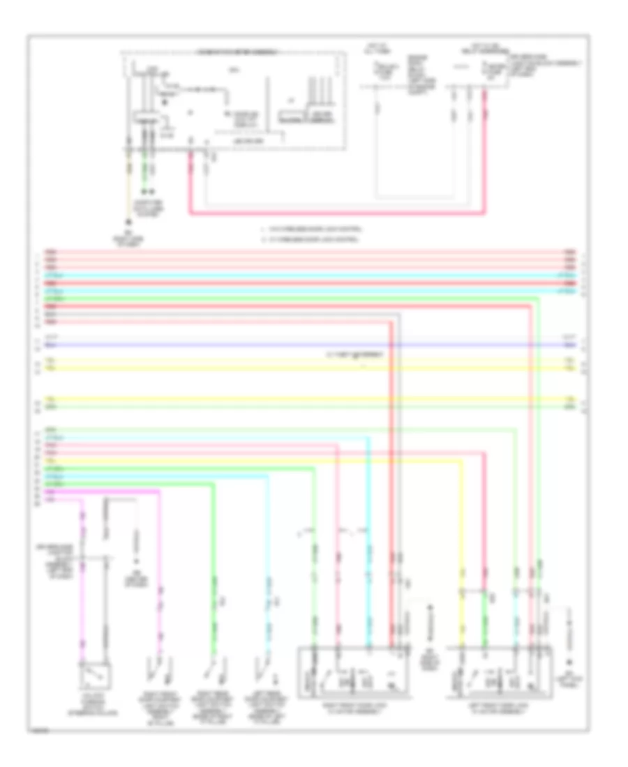
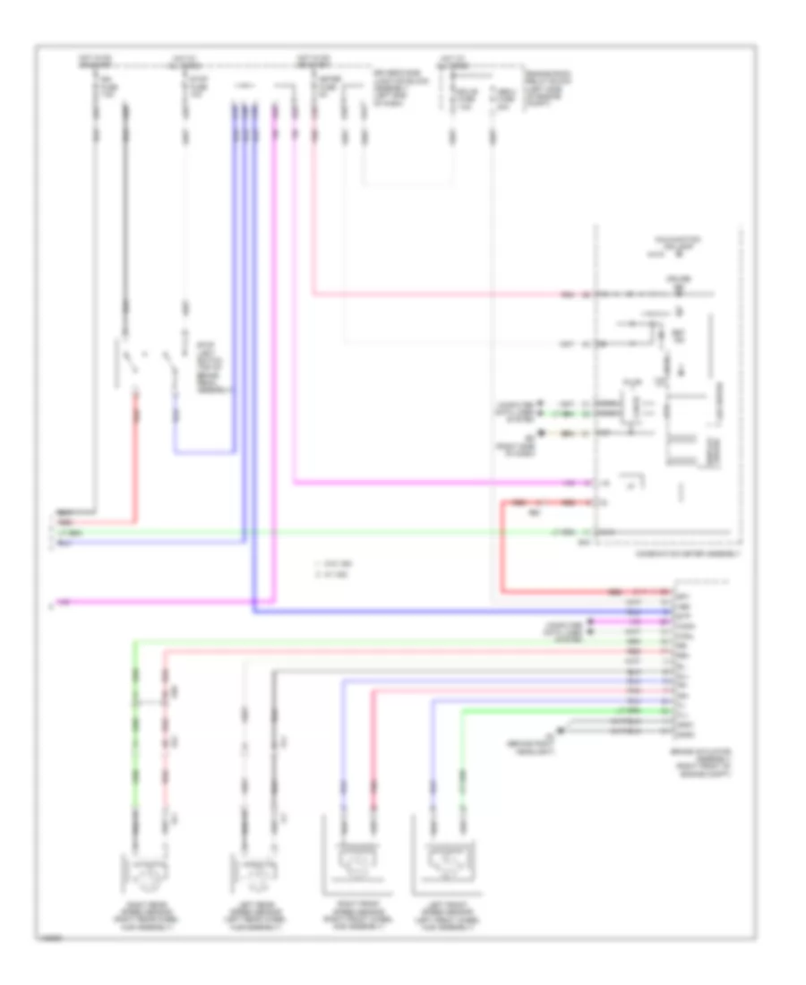
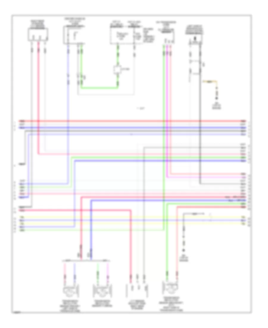
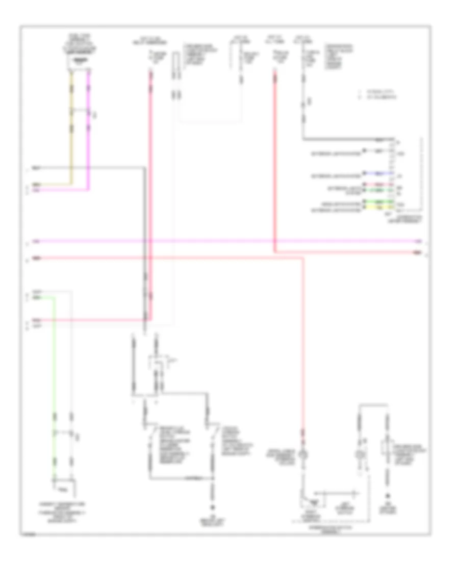
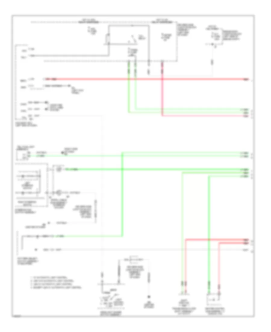
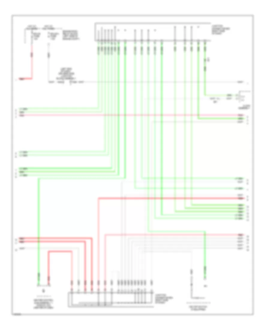
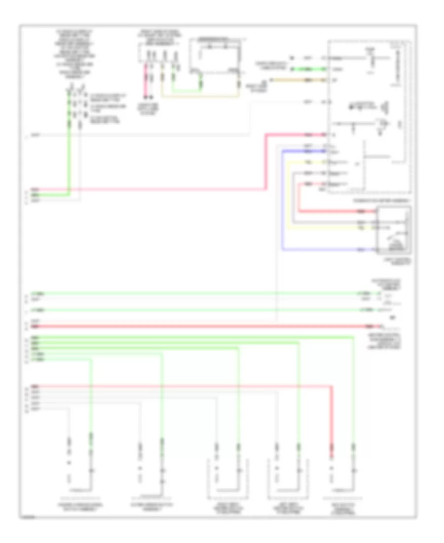
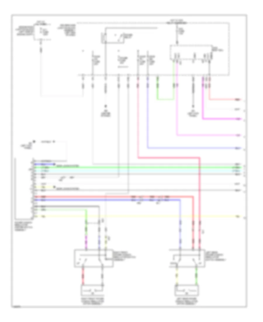
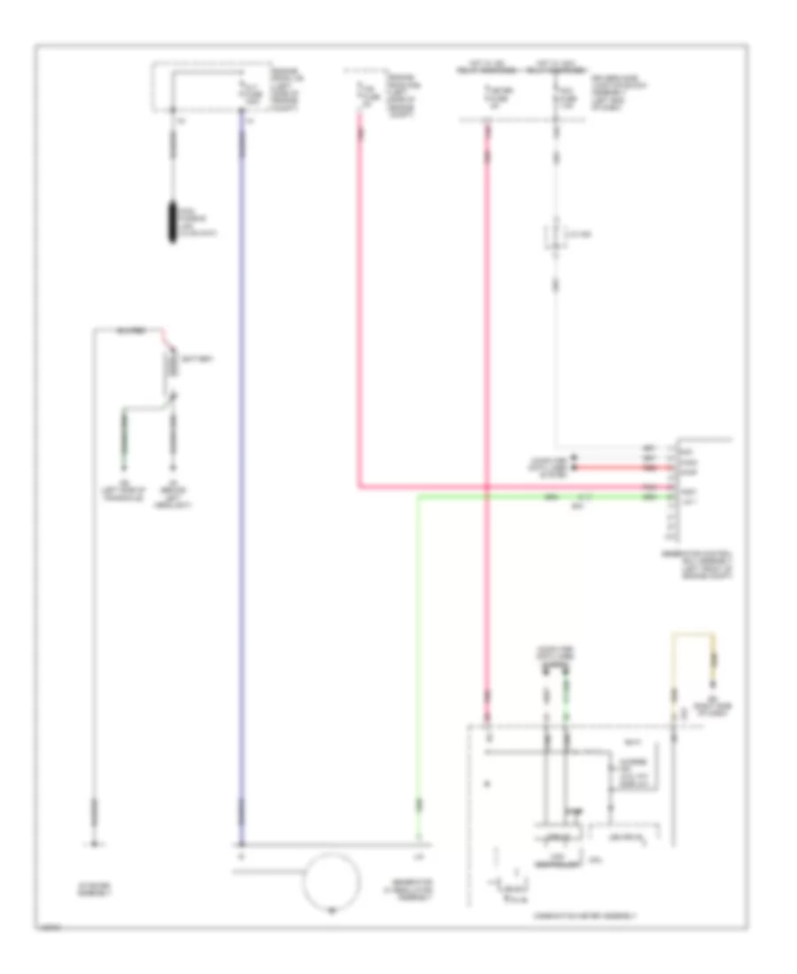
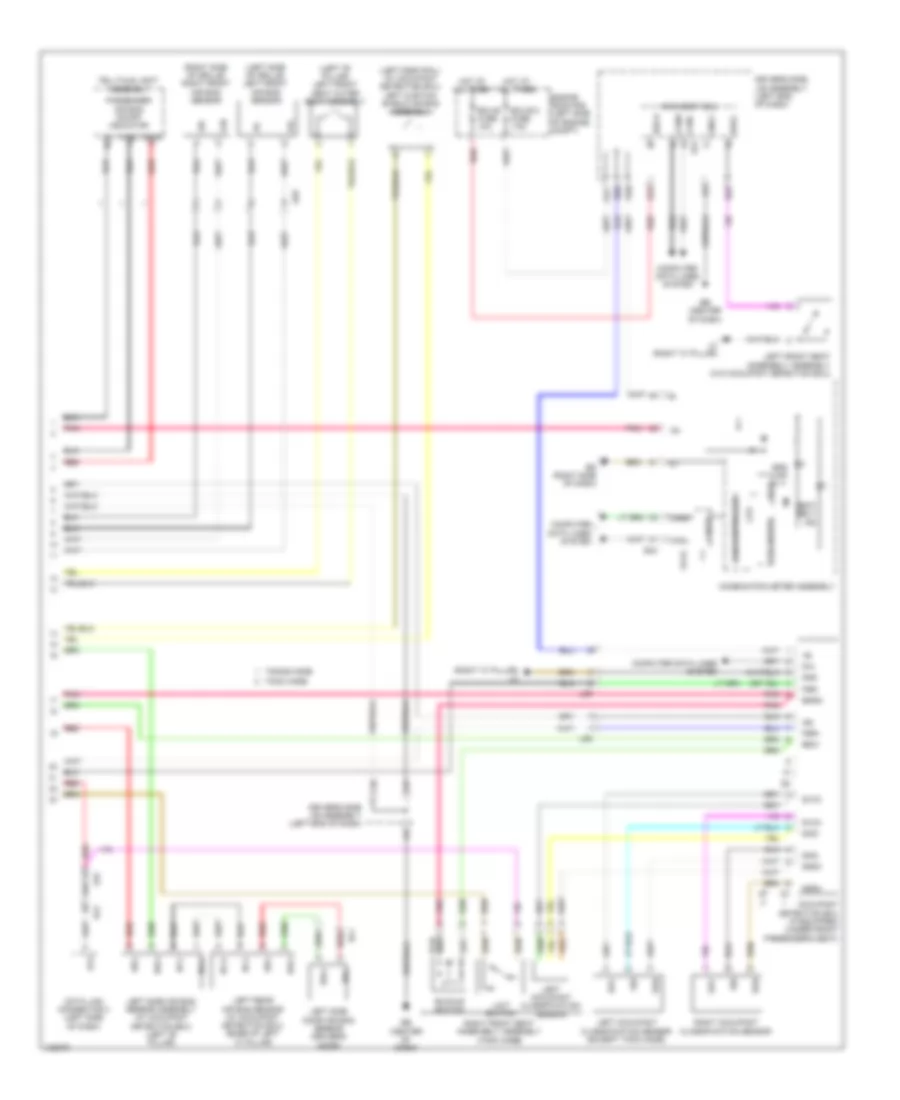
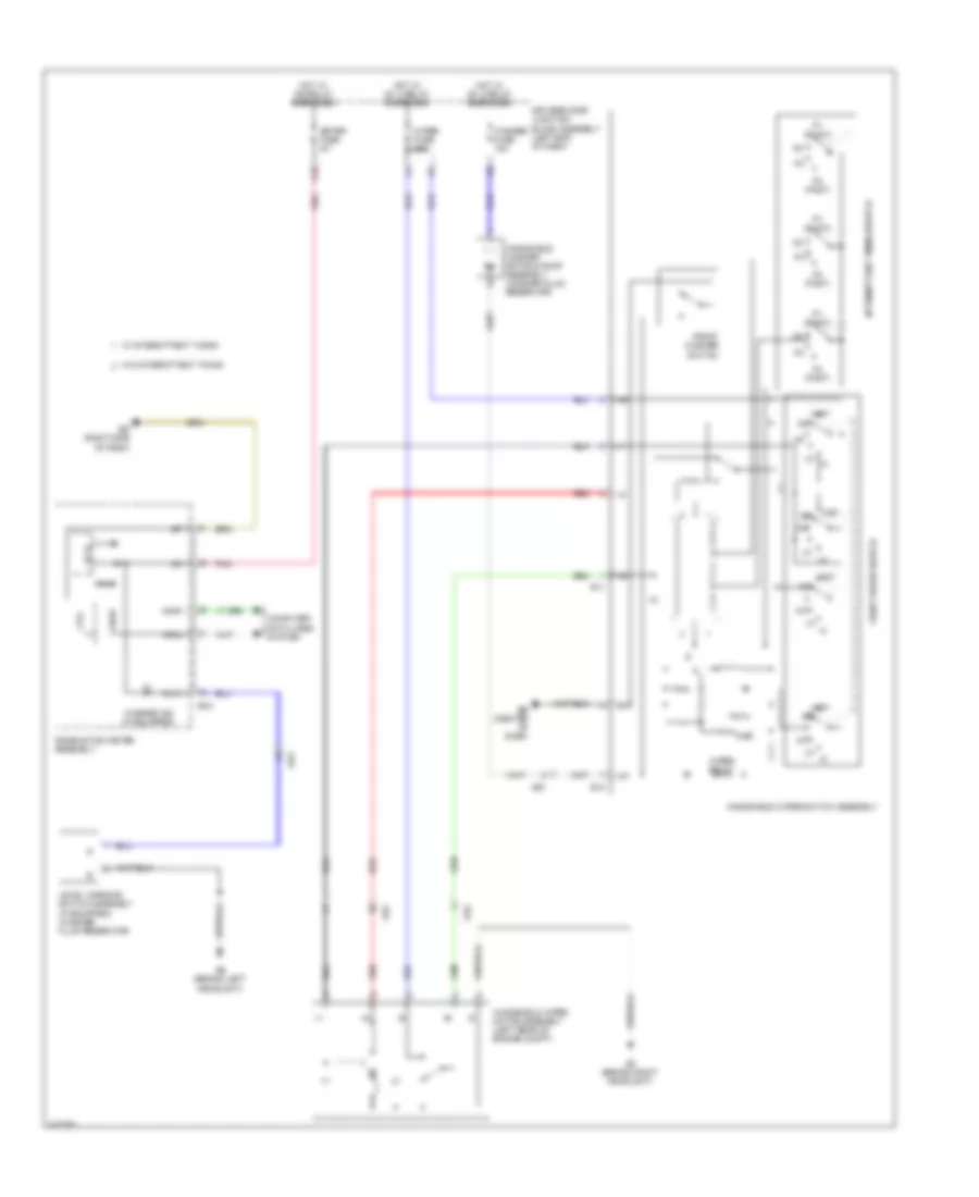
Automatic A/C Wiring Diagram (2 of 2) for Toyota Corolla LE Eco 2014
List of elements for Automatic A/C Wiring Diagram (2 of 2) for Toyota Corolla LE Eco 2014:
- (w/ ptc heater) ptc relay 1
- (w/ ptc heater) ptc relay 3
- +b1
- +bm
- 5v ic
- 5v+b
- A10
- A40
- A44
- Ab (behind left headlight)
- Ae3
- Af (right end of dash)
- Ambient temperature sensor (front of engine compt)
- B33
- Ba2
- Blower w/ fan motor sub assembly (right side of dash)
- Can controller
- Can i/f
- Canh
- Canl
- Combination meter assembly
- Computer data lines system
- Cooling fan ecu (left front of engine compt)
- Cooling fan motor (right side of dash)
- Cpu
- D40
- Driver side j/b assembly (left end of dash)
- E.f.i. engine coolant temperature sensor (rear of engine)
- E1 a31
- E43
- Eb (center of dash)
- Ec (right kick panel)
- Ecm (left side of engine compt)
- Eco ind
- Eco mode ind
- Eco switch assembly (if equipped)
- Ecu-b 2 fuse 7.5a
- Ed (right side of dash)
- Ef1
- Efi 1 fuse 10a
- Engine room r/b (left side of engine compt)
- Etcs fuse 10a
- Ethw
- Fan relay 1
- Gnd
- Hot at all times
- Hot in on or start
- Htr sub 1 fuse 30a
- Htr sub 3 fuse 30a
- I/f
- Ig+
- Interior lights system
- Led drive
- Pnk
- Quick heater assembly (w/ ptc heater) (on hvac assembly)
- Red
- Rfc
- Room temperature sensor (center of dash)
- Solar sensor (right side of dash)
- Ss+
- Ss-
- Thw
- Tx1+
- Tx1-
- W/o tft display
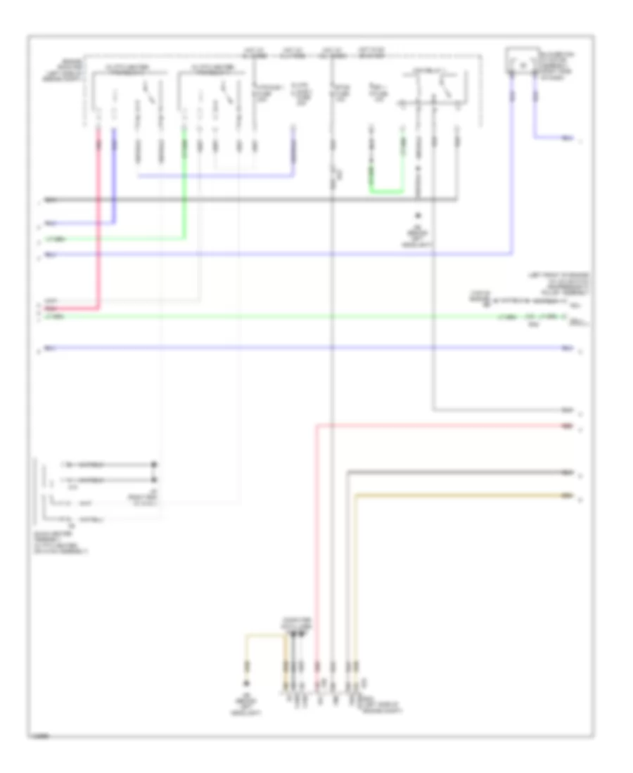
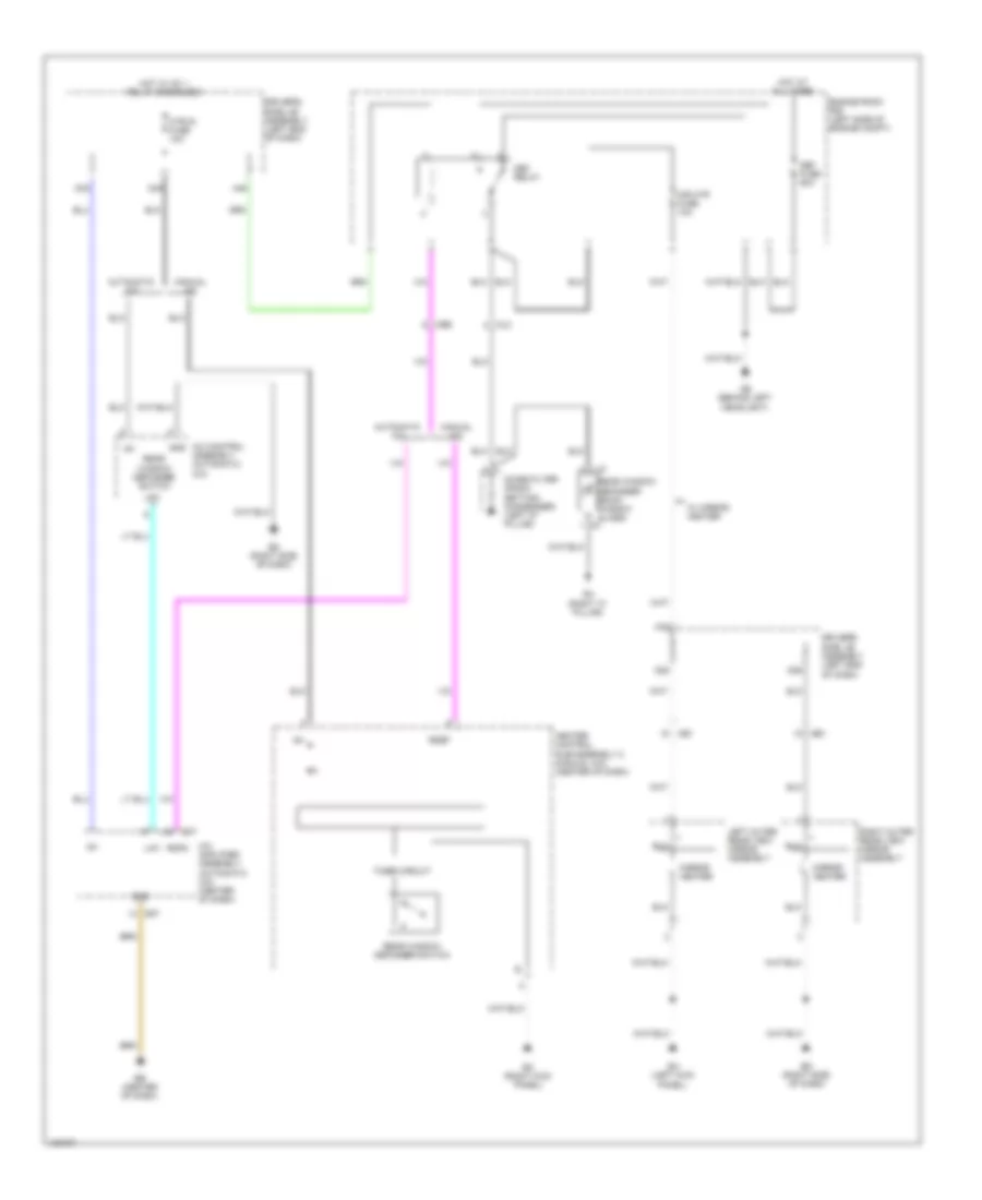
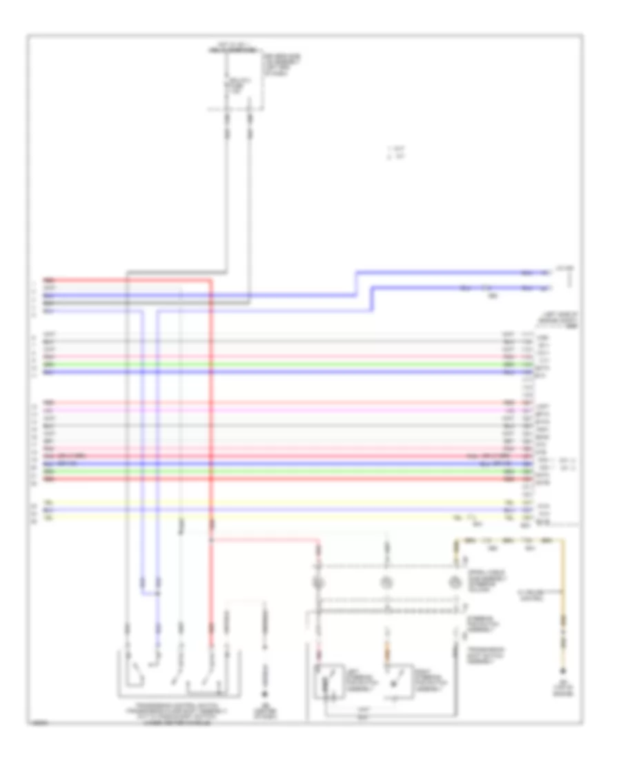
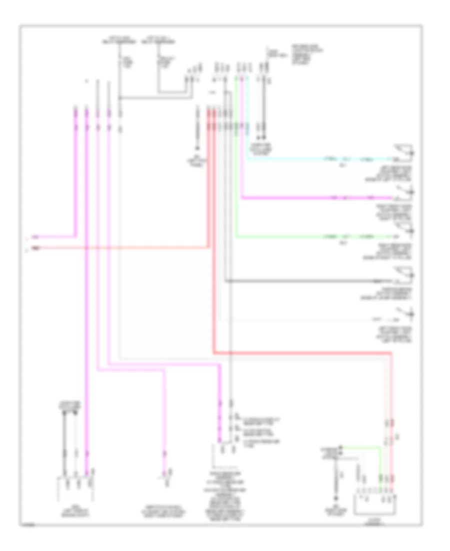
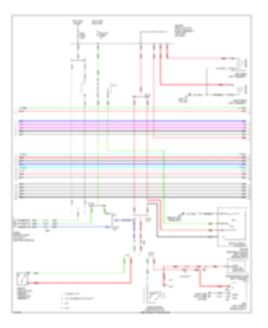
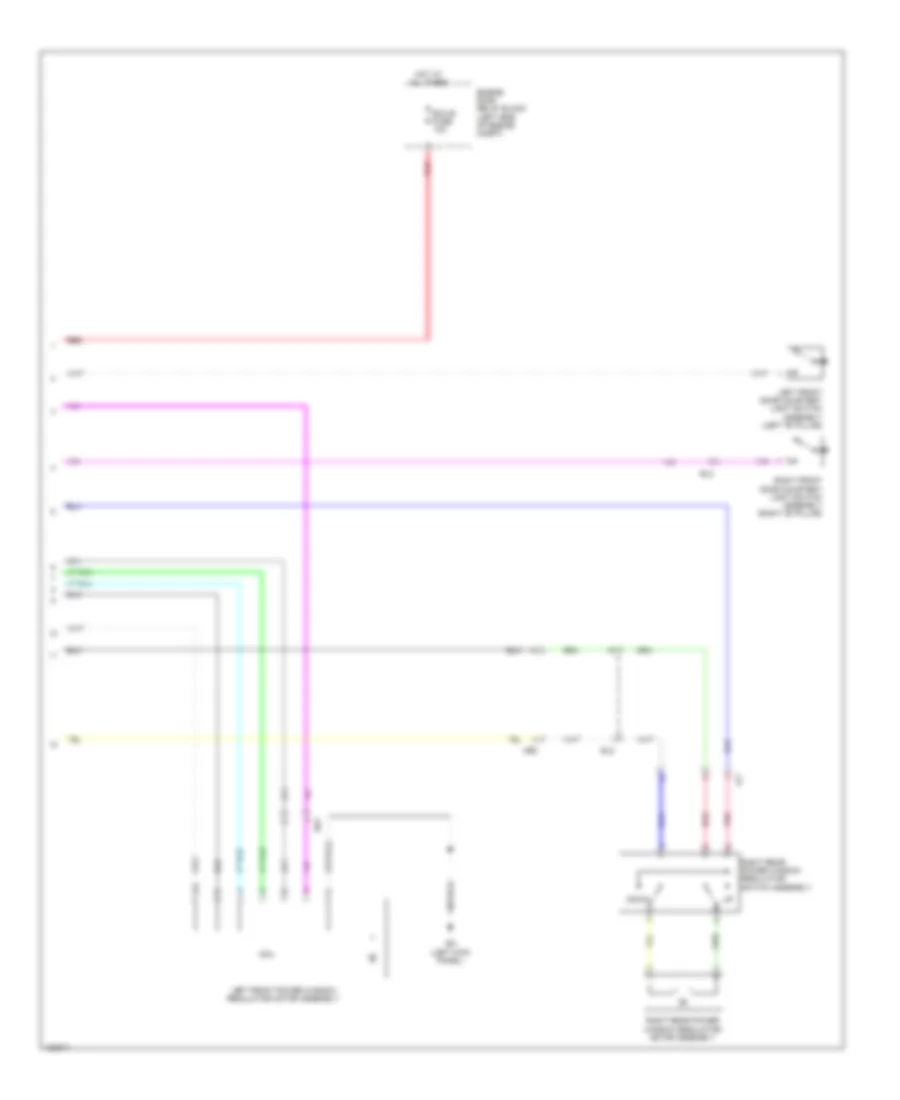
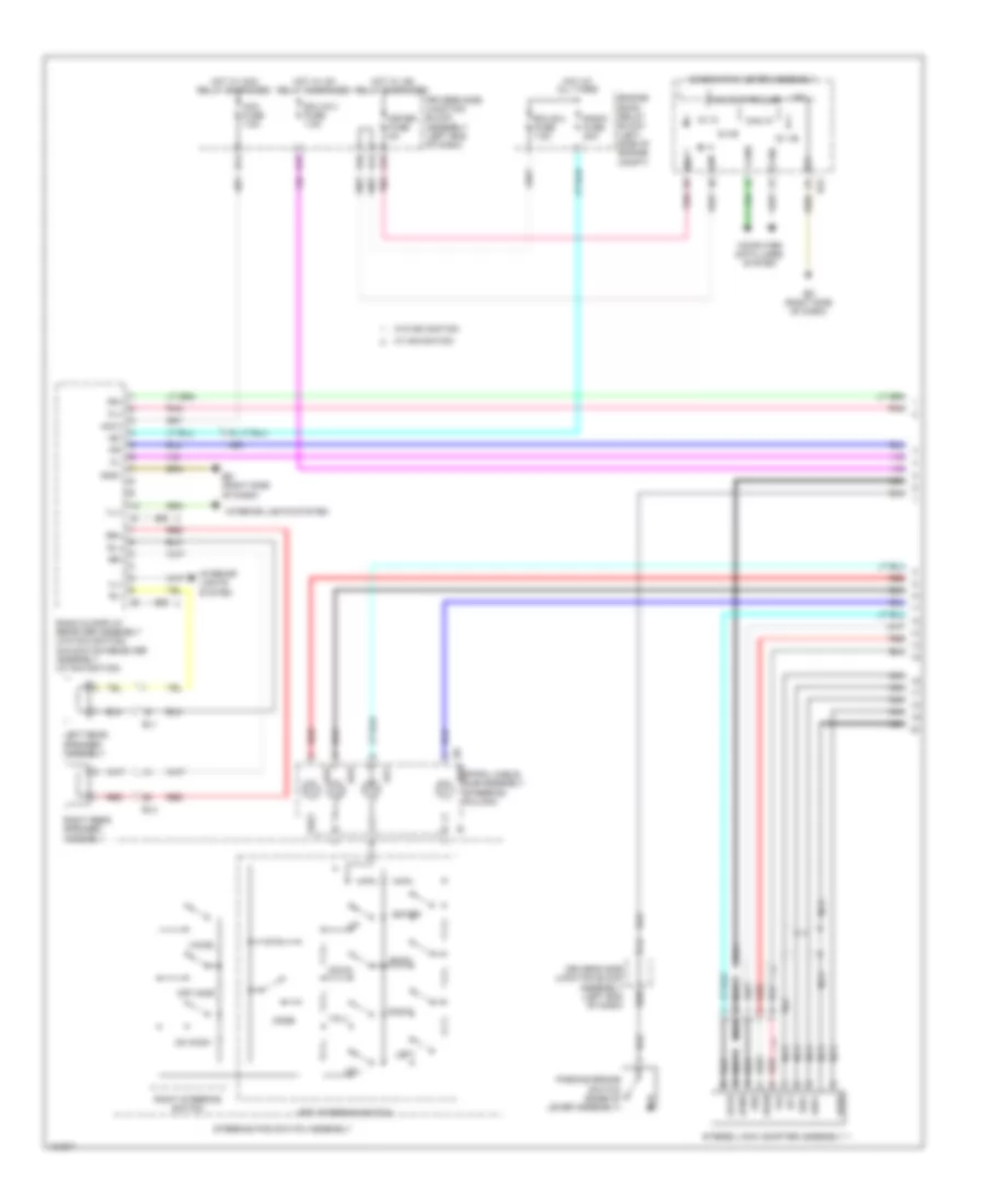
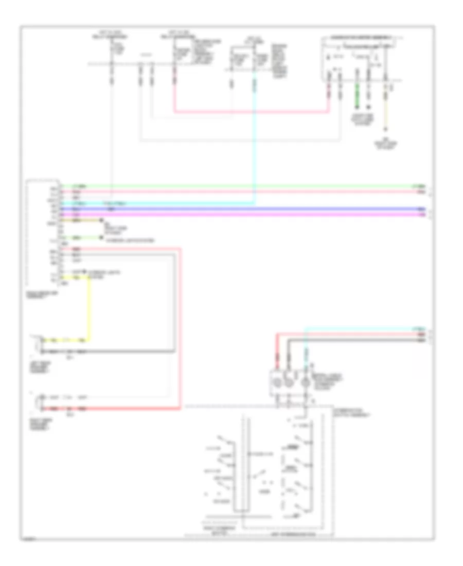
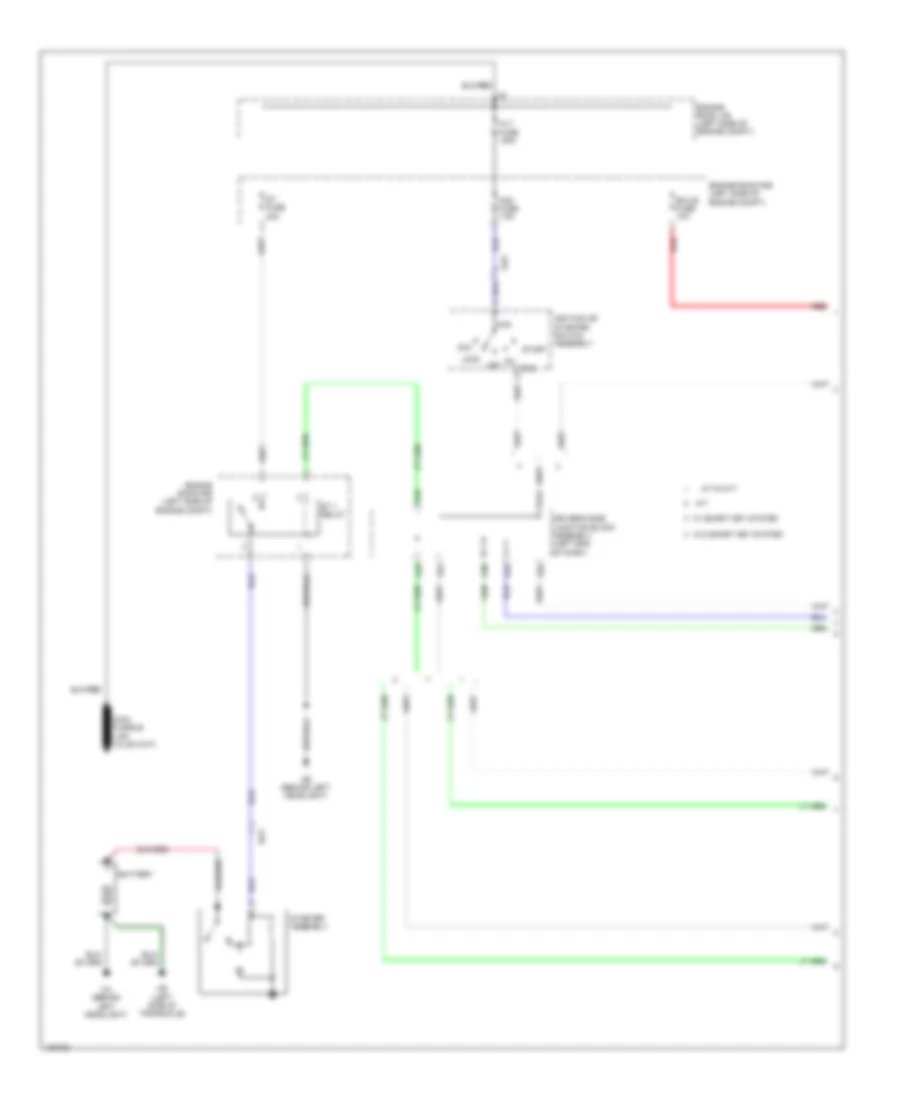
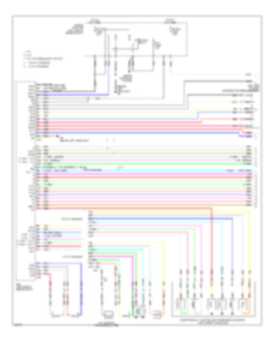
Manual A/C Wiring Diagram (1 of 3) for Toyota Corolla LE Eco 2014
List of elements for Manual A/C Wiring Diagram (1 of 3) for Toyota Corolla LE Eco 2014:
- (center of dash) eb
- A/c
- A/c amplifier assembly (center of dash)
- A/c pressure sensor (w/ a/c switch) (right front of engine compt)
- A/c switch (if equipped)
- A/c+
- A25
- A26
- Acid
- Ae1
- Ae6
- Aind
- Canh
- Canl
- Center r/b (center of dash)
- Computer data lines system
- Cooler thermistor 1 (w/ a/c switch) (center of dash)
- D23
- D24
- D42
- D43
- D44
- D46
- Damper servo sub assembly 1 (center of dash)
- Driver side j/b assembly (left end of dash)
- Ed (right side of dash)
- Engine room r/b (left side of engine compt)
- F/d
- Free
- Frs
- Gnd
- Heat
- Heater control sub assembly 1 (center of dash)
- Heater control sub assembly 3
- Hot at all times
- Hot in on or start
- Htr fuse 50a
- Htr relay
- Htr-ig fuse 10a
- Ig+
- Ill+
- Ill-
- Interior lights system
- Led
- Led+
- Lock
- Max hot switch (if equipped)
- Pnk
- Pre
- Ptc1
- Ptc2
- Rdi fuse 30a
- Rec
- Red
- S5-3
- Sblw
- Sg-2
- Sg-3
- Sol+
- W/ a/c switch
- W/ max hot switch
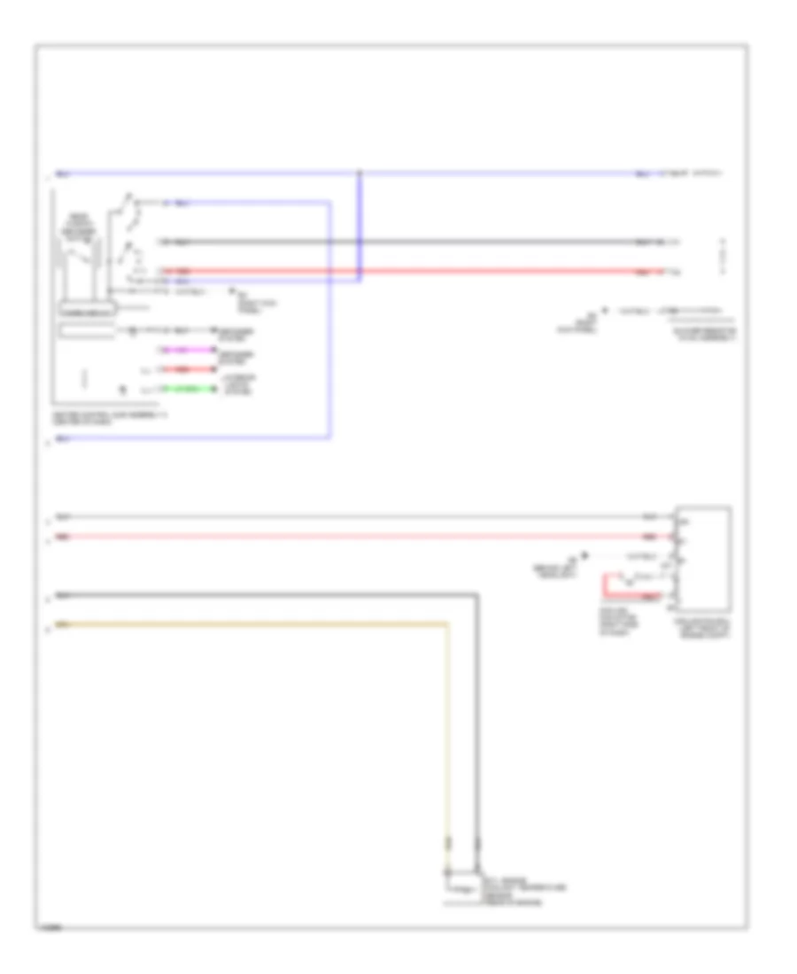
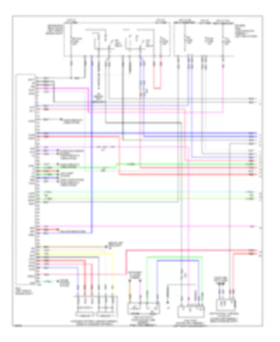
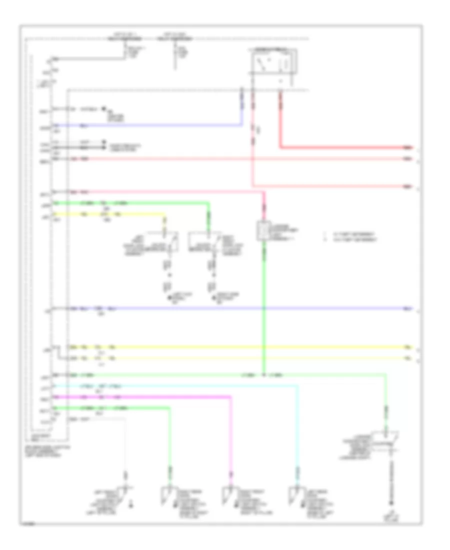
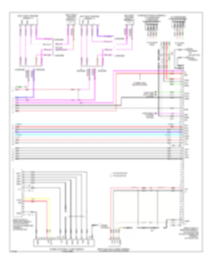
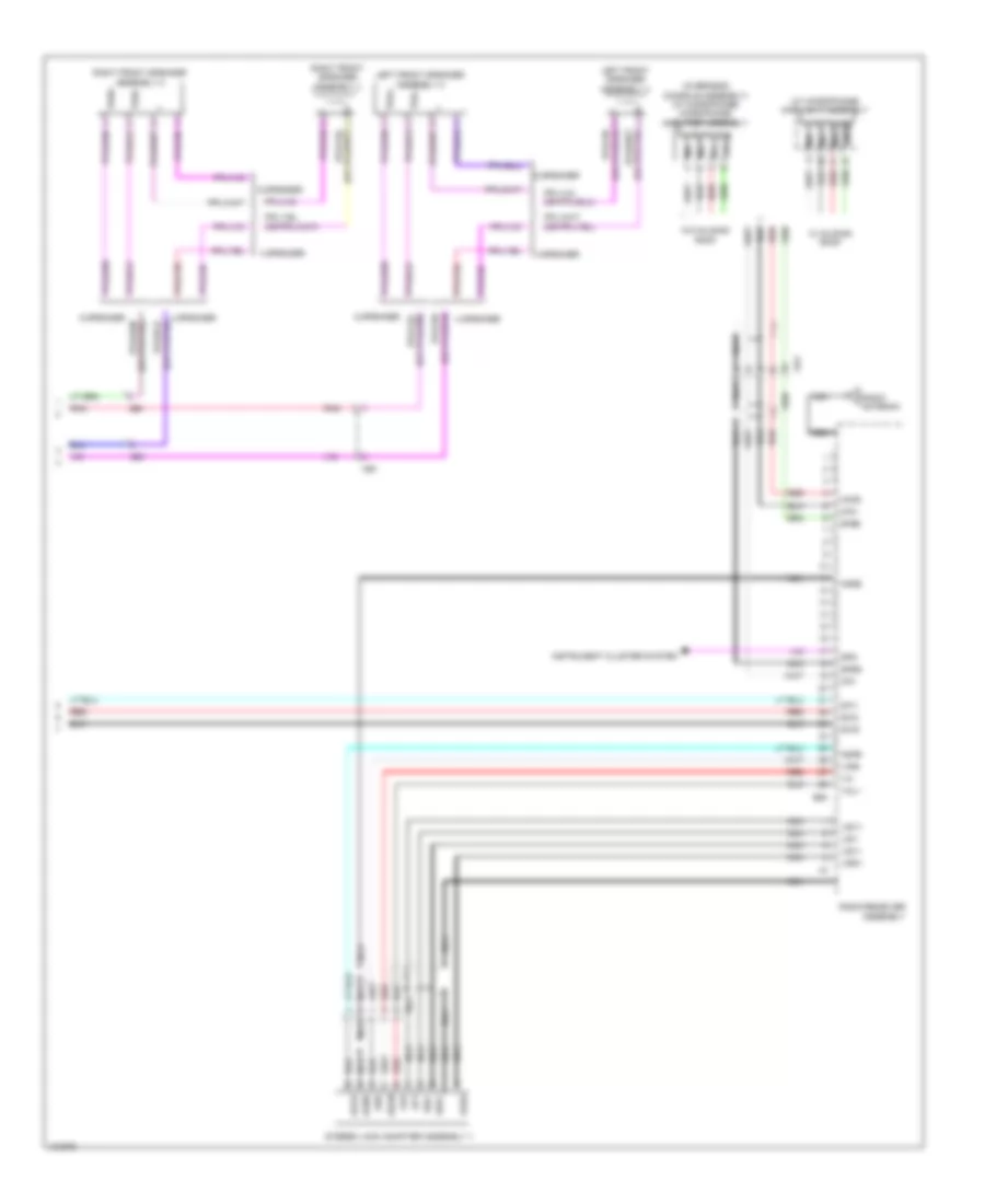
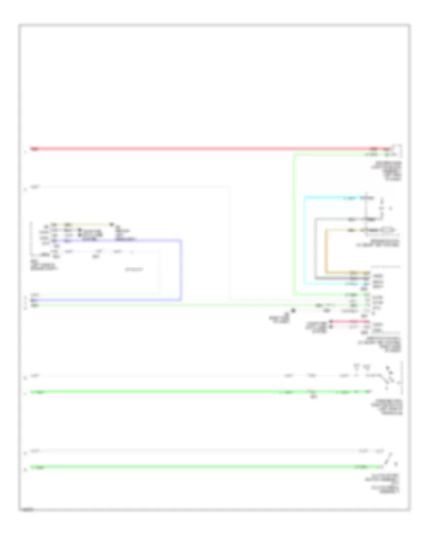
Manual A/C Wiring Diagram (2 of 3) for Toyota Corolla LE Eco 2014
List of elements for Manual A/C Wiring Diagram (2 of 3) for Toyota Corolla LE Eco 2014:
- (left front of engine) (w/ a/c switch) compressor w/ pulley assembly
- (top of engine) bb
- (w/ ptc heater) ptc relay 1
- (w/ ptc heater) ptc relay 3
- +bm
- A10
- A40
- Ab (behind left headlight)
- Af (right end of dash)
- B33
- Ba2
- Blower fan w/ motor assembly (right side of dash)
- Canh
- Canl
- Computer data lines system
- Ecm (left side of engine compt) ethw
- Efi 1 fuse 10a
- Engine room r/b (left side of engine compt)
- Etcs fuse 10a
- Fan relay 1
- Hot at all times
- Hot in on or start
- Htr sub 1 fuse 30a
- Htr sub 3 fuse 30a
- Pnk
- Quick heater assembly (w/ ptc heater) (on hvac assembly)
- Red
- Rfc
- Sol+
- Sol-
- Thw
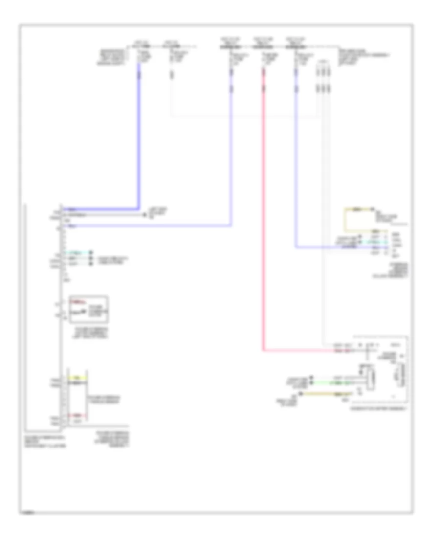
Manual A/C Wiring Diagram (3 of 3) for Toyota Corolla LE Eco 2014
List of elements for Manual A/C Wiring Diagram (3 of 3) for Toyota Corolla LE Eco 2014:
- +b1
- Ab (behind left headlight)
- Blower resistor (hvac assembly)
- Cooling fan ecu (left front of engine compt)
- Cooling fan motor (right side of dash)
- Defogger system
- E.f.i. engine coolant temperature sensor (rear of engine)
- E1 a31
- Ec (right kick panel)
- Heater control sub assembly 2 (center of dash)
- Ill+
- Ill-
- Interior lights system
- Rear window defogger switch
- Red
- Timer circuit
ANTI-LOCK BRAKES
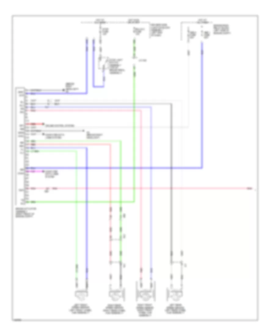
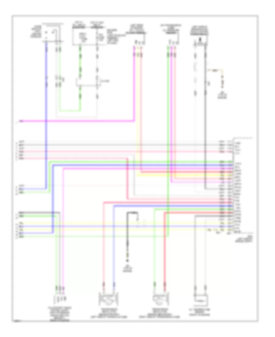
Anti-lock Brakes Wiring Diagram, with VSC (1 of 2) for Toyota Corolla LE Eco 2014
List of elements for Anti-lock Brakes Wiring Diagram, with VSC (1 of 2) for Toyota Corolla LE Eco 2014:
- (behind right headlight) ac
- +bm
- +bs
- A18
- A19
- A35
- A56
- Abs 1 fuse 50a
- Abs 2 fuse 30a
- Ac (behind right headlight)
- Ae4
- Ae6
- Al1
- Brake actuator assembly (right front of engine compt)
- Canh
- Canl
- Computer data lines system
- Cruise control system
- Csw
- Driver's side junction block assembly (left end of dash)
- Ecu-ig 2 fuse 10a
- El2
- Engine room relay block (left side of engine compt)
- Fl+
- Fl-
- Fr+
- Fr-
- Gnd1
- Gnd2
- Hot at all times
- Hot in on or start
- Ig1
- J/c a38
- Left front speed sensor (left front wheel hub assembly)
- Left rear speed sensor (left rear wheel hub assembly)
- Pnk
- Red
- Right front speed sensor (right front wheel hub assembly)
- Right rear speed sensor (right rear wheel hub assembly)
- Rl+
- Rl-
- Rr+
- Rr-
- Sp1
- Stop fuse 10a
- Stop light switch assembly (top of brake pedal assembly)
- Stp
- Hl1
- Jl1
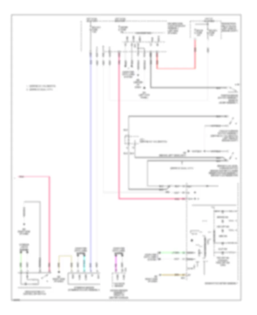
Anti-lock Brakes Wiring Diagram, with VSC (2 of 2) for Toyota Corolla LE Eco 2014
List of elements for Anti-lock Brakes Wiring Diagram, with VSC (2 of 2) for Toyota Corolla LE Eco 2014:
- 2zr-fae (w/ valvematic)
- 2zr-fe (w/ dual vvt-i)
- 5v ic
- 5v+b
- A24
- A44
- Ab (behind left headlight)
- Abs ind
- Ae3
- Air bag sensor assembly (front of center console)
- Bat
- Becu
- Brake fluid level warning switch (brake master cylinder reservoir sub-assembly) (brake fluid reservoir)
- Brake ind
- C18
- C55
- Can controller
- Can i/f
- Canh
- Canl
- Combination meter assembly
- Computer data lines system
- Cpu
- D12
- D22
- D40
- Driver's side junction block assembly (left end of dash)
- E14
- E30
- E31
- E43
- Ea (left kick panel)
- Eb (center of dash)
- Ecu-b 2 fuse 7.5a
- Ecu-b fuse 10a
- Ecu-ig 3 fuse 7.5a
- Ed (right side of dash)
- Engine room relay block (left side of engine compt)
- Ess
- Gnd1
- Hot at all times
- Hot in on or start
- Ig+
- Interior lights system
- J/c 1 (2zr-fae (w/ valvematic))
- Led driver
- Main body ecu
- Meter fuse 5a
- Parking brake switch assembly (base of lever assembly)
- Pkb
- Pnk
- Red
- Slip ind
- Steering sensor (steering column assembly)
- Trc off ind (canada) trac off ind (usa)
- Vacuum warning switch assembly (2zr-fae (w/ valvematic)) (left rear of engine compt)
- Vehicle stability control off switch
- Vsc off ind
- Yaw rate sensor
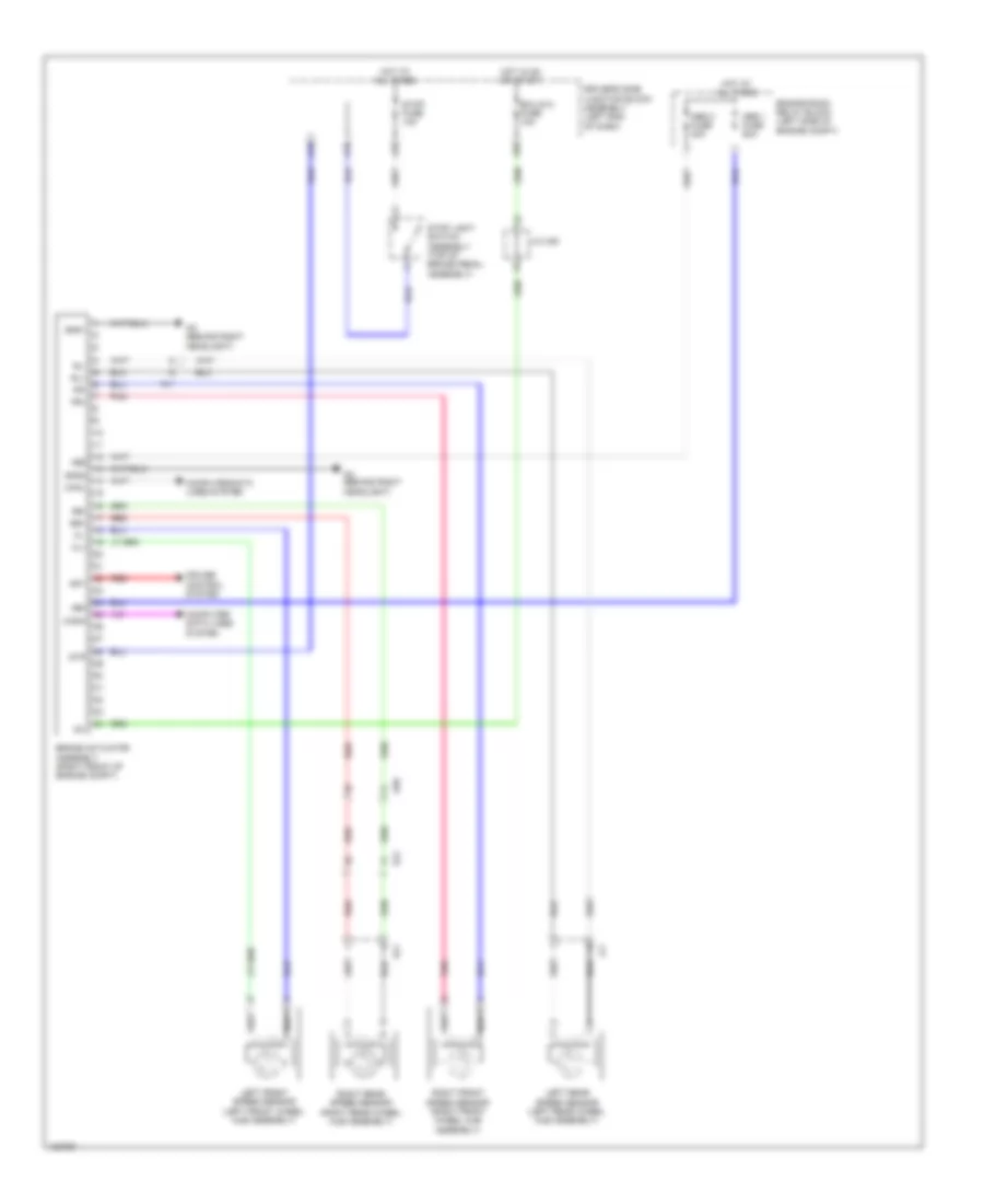
Anti-lock Brakes Wiring Diagram, without VSC (1 of 2) for Toyota Corolla LE Eco 2014
List of elements for Anti-lock Brakes Wiring Diagram, without VSC (1 of 2) for Toyota Corolla LE Eco 2014:
- +bm
- +bs
- A18
- A19
- A35
- A56
- Abs 1 fuse 50a
- Abs 2 fuse 30a
- Ac (behind right headlight)
- Ae6
- Al1
- Brake actuator assembly (right front of engine compt)
- Canh
- Canl
- Computer data lines system
- Cruise control system
- Driver's side junction block assembly (left end of dash)
- Ecu-ig 2 fuse 10a
- El2
- Engine room relay block (left side of engine compt)
- Fl+
- Fl-
- Fr+
- Fr-
- Gnd1
- Gnd2
- Hot at all times
- Hot in on or start
- Ig1
- J/c a38
- Left front speed sensor (left front wheel hub assembly)
- Left rear speed sensor (left rear wheel hub assembly)
- Pnk
- Red
- Right front speed sensor (right front wheel hub assembly)
- Right rear speed sensor (right rear wheel hub assembly)
- Rl+
- Rl-
- Rr+
- Rr-
- Sp1
- Stop fuse 10a
- Stop light switch assembly (top of brake pedal assembly)
- Stp
- Hl1
- Jl1
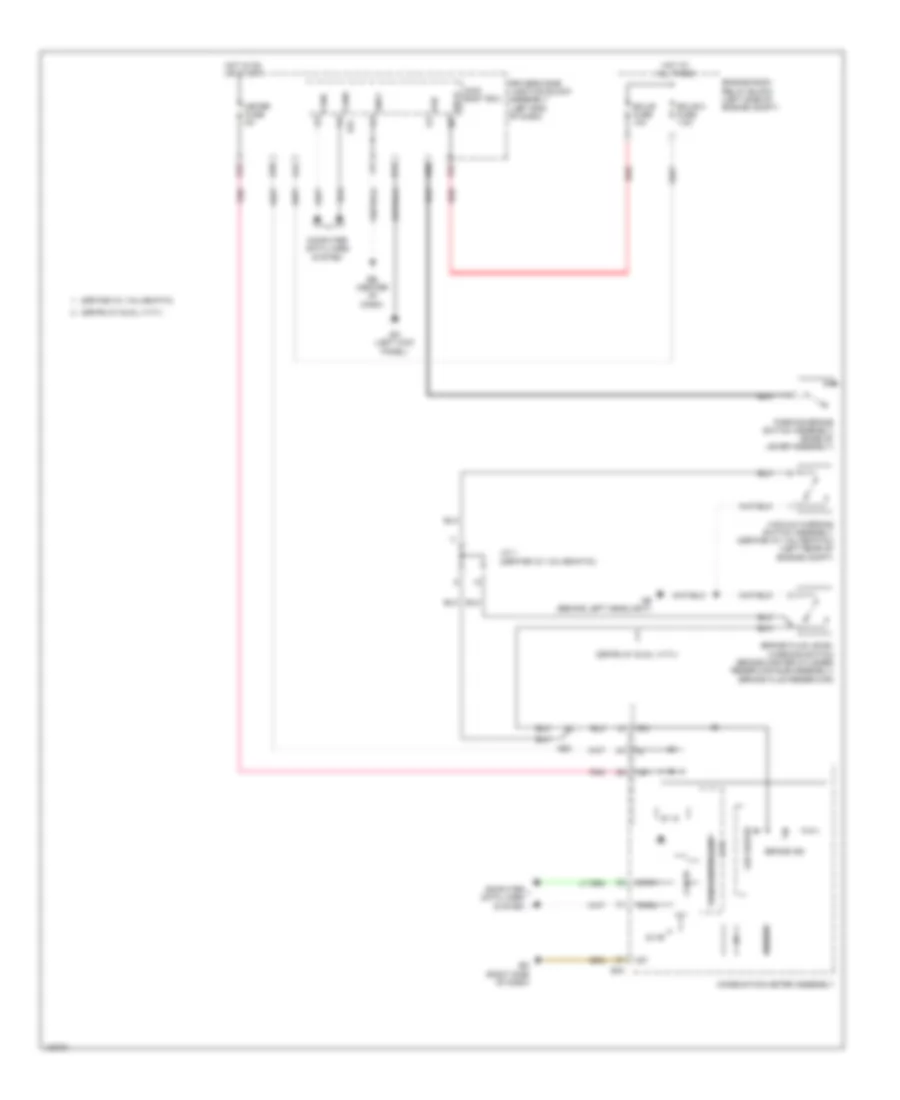
Anti-lock Brakes Wiring Diagram, without VSC (2 of 2) for Toyota Corolla LE Eco 2014
List of elements for Anti-lock Brakes Wiring Diagram, without VSC (2 of 2) for Toyota Corolla LE Eco 2014:
- 2zr-fae (w/ valvematic)
- 2zr-fe (w/ dual vvt-i)
- 5v ic
- 5v+b
- A24
- A44
- Ab (behind left headlight)
- Ae3
- Becu
- Brake fluid level warning switch (brake master cylinder reservoir sub-assembly) (brake fluid reservoir)
- Brake ind
- Buzzer
- C55
- Can controller
- Can i/f
- Canh
- Canl
- Combination meter assembly
- Computer data lines system
- Cpu
- D12
- D40
- Driver's side junction block assembly (left end of dash)
- E30
- E31
- E43
- Ea (left kick panel)
- Eb (center of dash)
- Ecu-b 2 fuse 7.5a
- Ecu-b fuse 10a
- Ed (right side of dash)
- Engine room relay block (left side of engine compt)
- Gnd1
- Hot at all times
- Hot in on or start
- I/f
- Ig+
- J/c 1 (2zr-fae (w/ valvematic))
- Led driver
- Main body ecu
- Meter fuse 5a
- Parking brake switch assembly (base of lever assembly)
- Pkb
- Pnk
- Red
- Vacuum warning switch assembly (2zr-fae (w/ valvematic)) (left rear of engine compt)
ANTI-THEFT
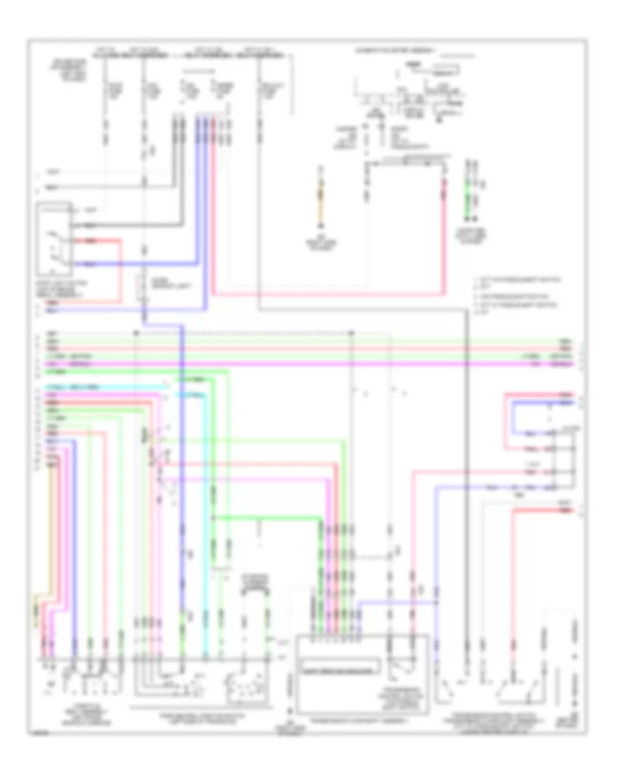
Forced Entry Wiring Diagram, with Smart Key System (1 of 5) for Toyota Corolla LE Eco 2014
List of elements for Forced Entry Wiring Diagram, with Smart Key System (1 of 5) for Toyota Corolla LE Eco 2014:
- A24
- A34
- A38
- A53
- A54
- Ac (behind right headlight)
- Acc
- Acc fuse 7.5a
- Act+
- Act-
- Actd
- Ae4
- Becu
- Bk/dr lock relay
- Bzr
- C12
- C13
- C14
- C20
- C21
- C27
- C28
- C29
- C54
- Canh
- Canl
- Computer data lines system
- Courtesy
- D door unlock relay
- D/l back fuse 10a
- D/l-alt fuse 25a
- D/lock relay
- D/unlock relay
- D12
- Door control switch assembly
- Driver's side junction block assembly (left end of dash)
- Dumy
- E24
- E31
- E32
- E34
- E37
- E38
- E39
- Ea (left kick panel)
- Ecu-ig 1 fuse 7.5a
- Ed (right side of dash)
- El2
- Exterior lights system
- Flcy
- Frcy
- Ge1
- Gnd1
- Hcty
- He1
- He2
- Headlights system
- Hood courtesy switch (hood lock assembly)
- Horn
- Horns system
- Hot at all times
- Hot w/ acc relay energized
- Hot w/ ig1 1 relay energized
- Hrly
- Ile
- Ind
- Interior lights system
- Lb (left "c" pillar)
- Lcty
- Lgcy
- Lsfl
- Lsfr
- Lsr
- Luggage compartment door lock assembly (center of luggage compt)
- Main body ecu
- Pnk
- Power window regulator master switch assembly
- Rcty
- Red
- Right front door courtesy light switch assembly (right "b" pillar)
- Right rear door courtesy light switch assembly (base of right "c" pillar)
- Tr+
- Trly
- Ul1
- Ul3
- W/ theft deterrent
Forced Entry Wiring Diagram, with Smart Key System (2 of 5) for Toyota Corolla LE Eco 2014
List of elements for Forced Entry Wiring Diagram, with Smart Key System (2 of 5) for Toyota Corolla LE Eco 2014:
- (right front of engine compt) brake actuator assembly
- 5v ic
- 5v+b
- A44
- Aa (behind left headlight)
- Ae3
- Buzzer
- C55
- Can controller
- Can i/f
- Canh
- Canl
- Combination meter assembly
- Computer data lines system
- Cpu
- D11
- D28
- D40
- Door ind
- Driver display
- Driver's side junction block assembly (left end of dash)
- E43
- Ea (left kick panel)
- Ed (right side of dash)
- El1
- Electrical key ind
- Ge1
- He1
- He2
- Hot w/ ig2 relay energized
- I/f
- Ig+
- Led driver
- Left front door courtesy light switch assembly (left "b" pillar)
- Left front door lock w/ motor assembly
- Left rear door courtesy light switch assembly (base of left "c" pillar)
- Lock key
- Lssr
- Master ind
- Meter fuse 5a
- Pnk
- Red
- Right front door lock w/ motor assembly
- Sp1
- Tion detec- unlock
- Unlock key
- W/ tft display
- W/ theft deterrent
- W/ vsc
- W/o tft display
- W/o vsc
- Wireless door lock buzzer (left side of dash)
Forced Entry Wiring Diagram, with Smart Key System (3 of 5) for Toyota Corolla LE Eco 2014
List of elements for Forced Entry Wiring Diagram, with Smart Key System (3 of 5) for Toyota Corolla LE Eco 2014:
- Ante6
- Ante7
- Clgb
- Ecu-b 2 fuse 7.5a
- Ecu-b fuse 10a
- El1
- El2
- Engine room relay block (left side of engine compt)
- Hot at all times
- Indoor electrical key antenna assembly 2 (right side chassis, near b pillar)
- Indoor electrical key antenna assembly 3 (left rear of luggage compt)
- J/c 4 (base of left "c" pillar)
- Jl1
- Kl1
- La (left "b" pillar)
- Lb (left "c" pillar)
- Left rear door lock w/ motor assembly
- Lssr
- Red
- Right rear door lock w/ motor assembly
- S-horn fuse 10a
- S-horn relay (w/ theft deterrent)
- Security horn assembly
- Tion detec- unlock
Forced Entry Wiring Diagram, with Smart Key System (4 of 5) for Toyota Corolla LE Eco 2014
List of elements for Forced Entry Wiring Diagram, with Smart Key System (4 of 5) for Toyota Corolla LE Eco 2014:
- (left side of engine compt) ecm
- (right "c" pillar) tire pressure warning ecu & receiver (electrical key & tire pressure monitoring system receiver assembly)
- A40
- Ant1
- Ant2
- Ante8
- Canh
- Canl
- Certification ecu (right side of dash)
- Cg6b
- Cg7b
- Cg8b
- Clg6
- Clg7
- Clg8
- Clgb
- Computer data lines system
- Csel
- Data
- E58
- Ed (right side of dash)
- El1
- El2
- Ge2
- Gnd
- Idw
- J/c 4 (base of left c pillar)
- La (left "b" pillar)
- Lb (left "c" pillar)
- Lc (right "c" pillar)
- Luggage electrical key switch (top center of trunk lid)
- Neo
- Pnk
- Rco
- Rdam
- Rear electrical key antenna (rear bumper assembly)
- Red
- Right front door outside handle assembly
- Sens
- Smart door control receiver assembly
- Trg+
- Tsw5
- W/ tire pressure warning system
- W/o tire pressure warning system
Forced Entry Wiring Diagram, with Smart Key System (5 of 5) for Toyota Corolla LE Eco 2014
List of elements for Forced Entry Wiring Diagram, with Smart Key System (5 of 5) for Toyota Corolla LE Eco 2014:
- (right side chassis, near "b" pillar) indoor electrical key antenna assembly 1
- A19
- A24
- A35
- Accd
- Ae2
- Ae3
- Agnd
- Am2 fuse 7.5a
- Ant1
- Ant2
- Ante5
- Antenna coil
- Canh
- Canl
- Certification ecu (right side of dash)
- Cg1b
- Cg2b
- Cg5b
- Clg1
- Clg2
- Clg5
- Clgb
- Code
- Computer data lines system
- Cutb
- D39
- Driver's side junction block assembly (left end of dash)
- Dumy
- E57
- E59
- Ea (left kick panel)
- Ecu-b fuse 10a
- Ed (right side of dash)
- El2
- Engine room relay block (left side of engine compt)
- Engine switch
- Gnd
- He2
- Hot at all times
- Hot w/ ig2 relay energized
- Ig1d
- Ig2d
- Ign fuse 7.5a
- Ill-
- Ind
- Left front door outside handle assembly
- Lin
- Pnk
- Pos1
- Pos2
- Power distribution system
- Red
- Security ind
- Sen1
- Sen2
- Sens
- Shift interlock system
- Slp
- Slr+
- Spd
- Ss1
- Ss2
- Ssw1
- Ssw2
- Sta
- Star
- Starting/charging system
- Stop fuse 10a
- Stop light switch assembly (top of brake pedal assembly)
- Stp1
- Swil
- Telltale light assembly
- Trg+
- Tsw1
- Tsw2
- Txct
- Vc5
Forced Entry Wiring Diagram, without Smart Key System (1 of 3) for Toyota Corolla LE Eco 2014
List of elements for Forced Entry Wiring Diagram, without Smart Key System (1 of 3) for Toyota Corolla LE Eco 2014:
- A24
- A34
- A38
- A53
- A54
- Ac (behind right headlight)
- Acc
- Acc fuse 7.5a
- Act+
- Act-
- Actd
- Ae4
- Anti-theft system
- Becu
- Bk/dr lock relay
- Bzr
- C12
- C13
- C14
- C20
- C21
- C22
- C27
- C28
- C29
- C54
- Canh
- Canl
- Computer data lines system
- Courtesy
- D door unlock relay
- D/l back fuse 10a
- D/l-alt fuse 25a
- D/lock relay
- D/unlock relay
- Domr
- Door control switch assembly
- Door lock control switch
- Driver's side junction block assembly (left end of dash)
- Dumy
- E24
- E31
- E32
- E34
- E37
- E38
- E39
- Ea (left kick panel)
- Eb (center of dash)
- Ecu-ig 1 fuse 7.5a
- Ed (right side of dash)
- Exterior lights system
- Flcy
- Frcy
- Ge1
- Gnd1
- Hcty
- He1
- Headlights system
- Hood courtesy switch (hood lock assembly)
- Horn
- Horns system
- Hot at all times
- Hot w/ acc relay energized
- Hot w/ ig1 1 relay energized
- Hrly
- Ile
- Ill-
- Ind
- Interior lights system
- Ksw
- Lb (left "c" pillar)
- Lcty
- Lgcy
- Lock
- Lsfl
- Lsfr
- Lsr
- Luggage compartment door lock assembly (center of luggage compt)
- Main body ecu
- Pnk
- Power window regulator master switch assembly
- Prg
- Rcty
- Rda
- Red
- Security ind
- Telltale light assembly
- Tr+
- Trly
- Ul1
- Ul2
- Ul3
- Unlock
- W/ theft deterrent
- W/o wireless door lock control
Forced Entry Wiring Diagram, without Smart Key System (2 of 3) for Toyota Corolla LE Eco 2014
List of elements for Forced Entry Wiring Diagram, without Smart Key System (2 of 3) for Toyota Corolla LE Eco 2014:
- 5v ic
- 5v+b
- A44
- Buzzer
- C30
- C32
- C55
- Can controller
- Can i/f
- Canh
- Canl
- Combination meter assembly
- Computer data lines system
- Cpu
- D17
- D40
- Detection unlock
- Door ind (w/o tft display)
- Driver display
- Driver's side junction block assembly (left end of dash)
- E43
- Ea (left kick panel)
- Eb (center of dash)
- Ecu-b 2 fuse 7.5a
- Ed (right side of dash)
- El1
- El2
- Engine room relay block (left side of engine compt)
- Ge1
- He1
- He2
- Hot at all times
- Hot w/ ig2 relay energized
- I/f
- Ig+
- Key lock
- Key un- lock
- Led driver
- Left front door lock w/ motor assembly
- Left rear door courtesy light switch assembly (base of left "c" pillar)
- Lock
- Lock key
- Lssr
- Meter fuse 5a
- Pnk
- Red
- Right front door courtesy light switch assembly (right "b" pillar)
- Right front door lock w/ motor assembly
- Right rear door courtesy light switch assembly (base of right "c" pillar)
- Un- key
- Un-lock warning switch (steering column)
- W/ theft deterrent
- W/ wireless door lock control
- W/o wireless door lock control
Forced Entry Wiring Diagram, without Smart Key System (3 of 3) for Toyota Corolla LE Eco 2014
List of elements for Forced Entry Wiring Diagram, without Smart Key System (3 of 3) for Toyota Corolla LE Eco 2014:
- (left "c" pillar) door control receiver
- (left end of dash) driver's side junction block assembly
- (right "c" pillar) tire pressure warning ecu & receiver (door control & tire pressure monitoring system receiver assembly)
- A24
- Aa (behind left headlight)
- Detection unlock
- E31
- Ecu-b fuse 10a
- El1
- Engine room relay block (left side of engine compt)
- Gnd
- Hot at all times
- J/c 4 (base of left "c" pillar)
- Jl1
- Kl1
- Lb (left "c" pillar)
- Lc (right "c" pillar)
- Left front door courtesy light switch assembly (left "b" pillar)
- Left rear door lock w/ motor assembly
- Lssr
- Prg
- Rda
- Red
- Right rear door lock w/ motor assembly
- S-horn fuse 10a
- S-horn relay (w/ theft deterrent)
- Security horn assembly
- W/ theft deterrent
- W/ tire pressure warning system
- W/o tire pressure warning system
- Wireless door lock buzzer (left side of dash)
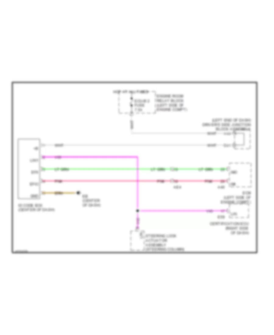
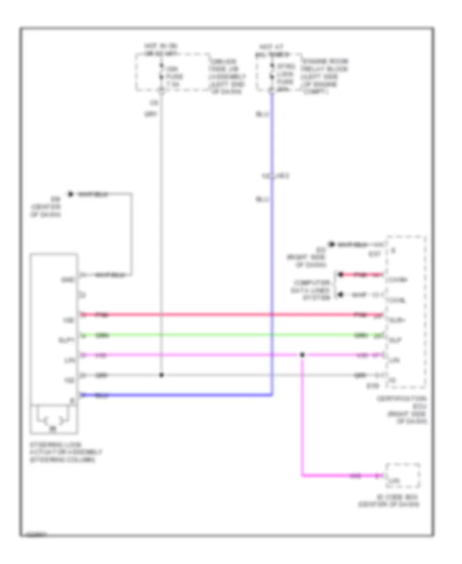
Immobilizer Wiring Diagram, with Smart Key System for Toyota Corolla LE Eco 2014
List of elements for Immobilizer Wiring Diagram, with Smart Key System for Toyota Corolla LE Eco 2014:
- (left end of dash) driver's side junction block assembly
- A40
- A44
- Ae4
- Certification ecu (right side of dash)
- D41
- E59
- Eb (center of dash)
- Ecm (left side of engine compt)
- Ecu-b 2 fuse 7.5a
- Efii
- Efio
- Engine room relay block (left side of engine compt)
- Gnd
- Hot at all times
- Id code box (center of dash)
- Imi
- Imo
- Lin
- Lin1
- Pnk
- Steering lock actuator assembly (steering column)
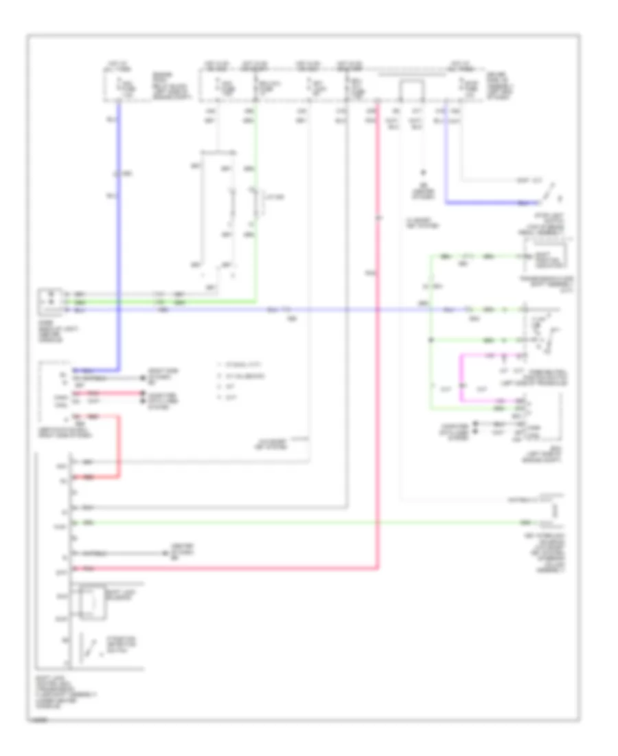
Immobilizer Wiring Diagram, without Smart Key System for Toyota Corolla LE Eco 2014
List of elements for Immobilizer Wiring Diagram, without Smart Key System for Toyota Corolla LE Eco 2014:
- A40
- A44
- Ae4
- Ant1
- Ant2
- C30
- C31
- C44
- Computer data lines system
- D17
- D41
- Driver's side junction block assembly (left end of dash)
- E32
- Eb (center of dash)
- Ecm (left side of engine compt)
- Ecu-b 2 fuse 7.5a
- Ed (right side of dash)
- Efii
- Efio
- Engine room relay block (left side of engine compt)
- Gnd
- Hot at all times
- Hot w/ ig2 relay energized
- Ign fuse 7.5a
- Ill-
- Imi
- Imo
- Ind
- Ksw
- Main body ecu (left end of dash)
- Pnk
- Red
- Security indicator
- Telltale light assembly
- Transponder key coil
- Transponder key ecu assembly (center of dash)
- Un-lock warning switch (steering column)
- W/ theft deterrent
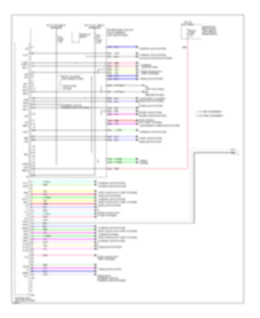
BODY CONTROL MODULES
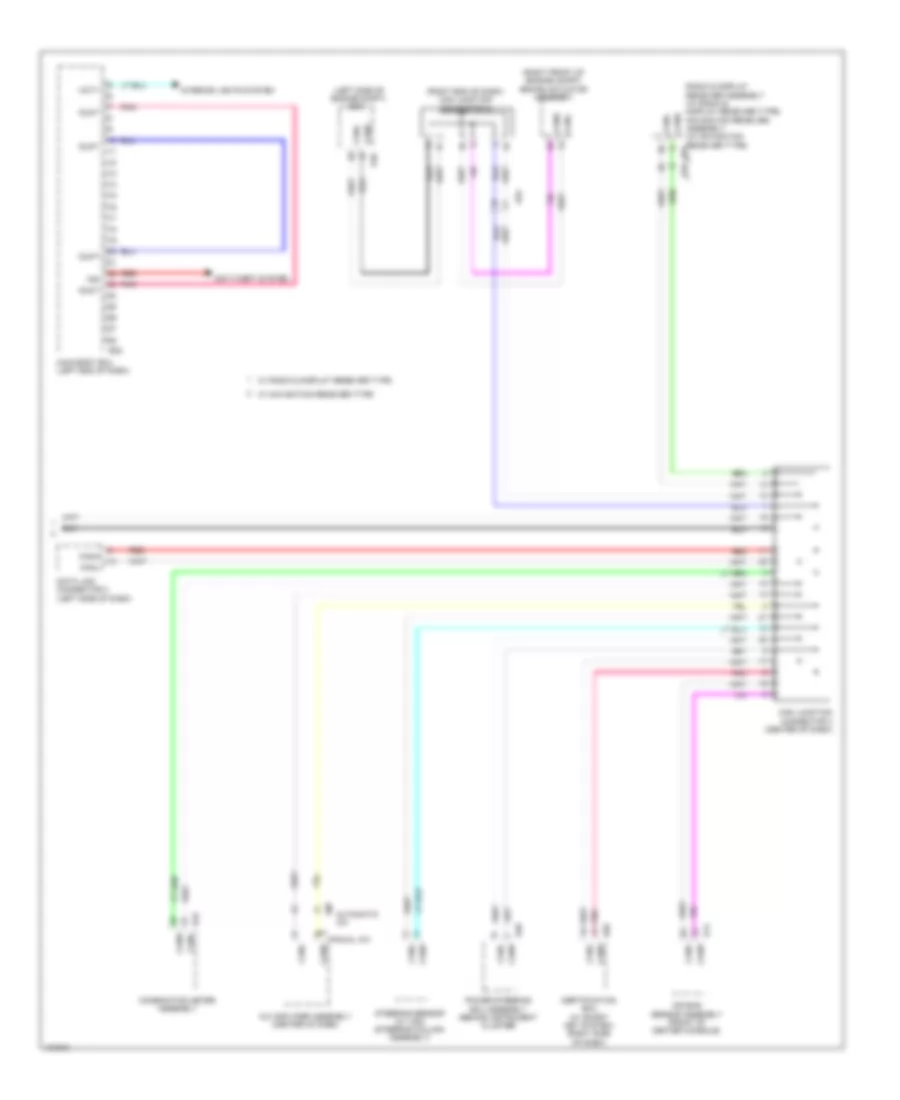
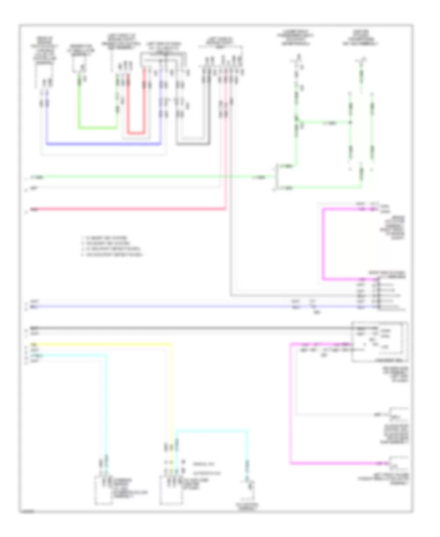
Body Control Modules Wiring Diagram (1 of 2) for Toyota Corolla LE Eco 2014
List of elements for Body Control Modules Wiring Diagram (1 of 2) for Toyota Corolla LE Eco 2014:
- (left end of dash)
- A24
- A28
- A34
- A38
- A49
- A50
- A53
- A54
- Acc
- Acc fuse 7.5a
- Act+
- Act-
- Actd
- Bctl
- Becu
- Bzr
- C41
- C42
- C43
- C49
- C52
- C53
- C54
- Canh
- Canl
- Cltb
- Clte
- Clts
- D12
- Dbkl
- Dim
- Dome cut relay
- Domr
- Door locks & anti- theft systems
- Door locks & anti-theft systems
- Door locks system
- Driver's side junction block assembly
- Drl
- E24
- E25
- E30
- E31
- E32
- E34
- E38
- E39
- E40
- Ea (left kick panel)
- Eb (center of dash)
- Ecu- ig 1 fuse 7.5a
- Ecu-b fuse 10a
- Engine room relay block (left side of engine compt)
- Exterior lights & interior lights systems
- Ffgo
- Ffog
- Flcy
- Frcy
- Gnd1
- Head
- Headlights system
- Headlights, exterior lights & interior lights systems
- Horn
- Horns system
- Hot at all times
- Hot w/ acc relay energized
- Hot w/ ig1 1 relay energized
- Hrly
- Ile
- Instrument cluster & headlights systems
- Interior lights system
- Koff
- Ksw
- Lcty
- Lgcy
- Lgyl bcyl
- Lin2
- Lsfl
- Lsfr
- Lsr
- Main body ecu (left end of dash)
- Navigation & sound systems
- Pkb
- Pnk
- Power tops system
- Power windows system
- Prg
- Rcty
- Rda
- Red
- Tail
- Tr+
- Trly
- Trunk, tailgate, fuel doors system
- Ul1
- Ul2
- Ul3
- W/ theft deterrent
- W/o theft deterrent
- Warning systems
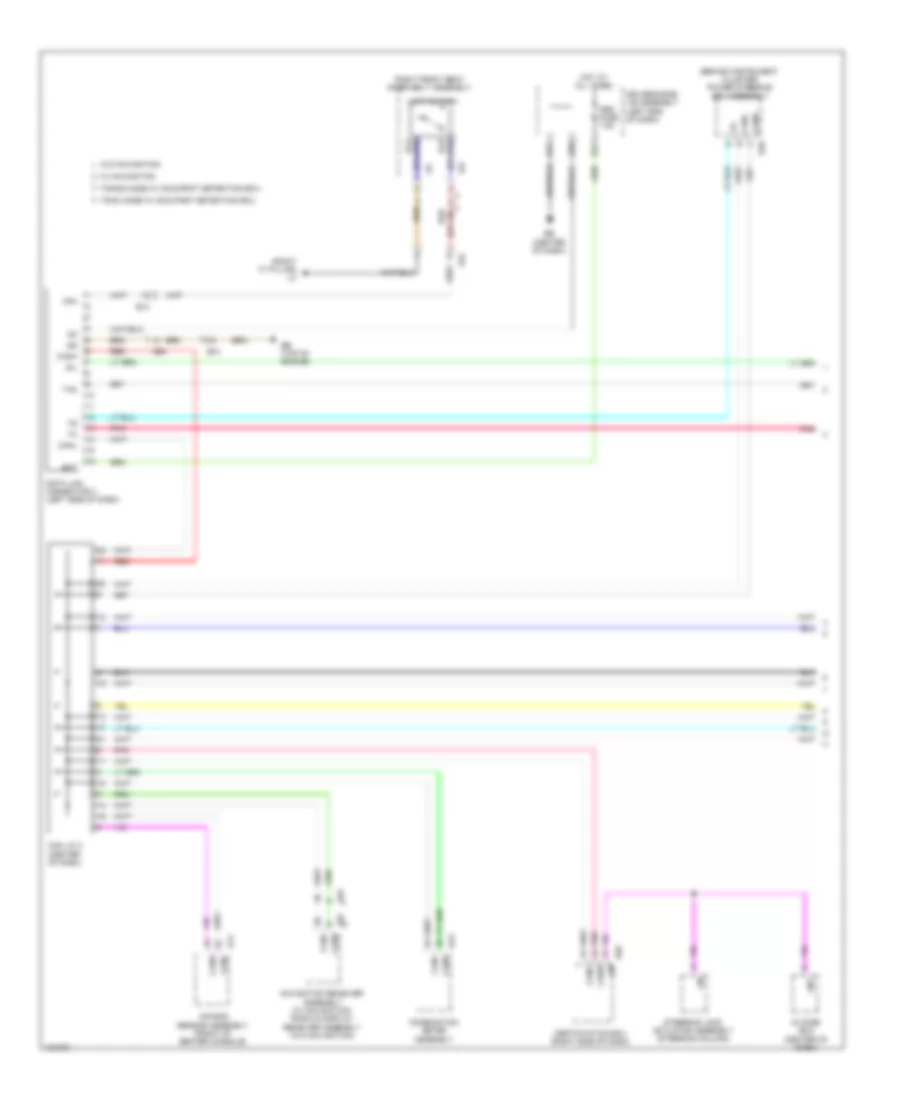
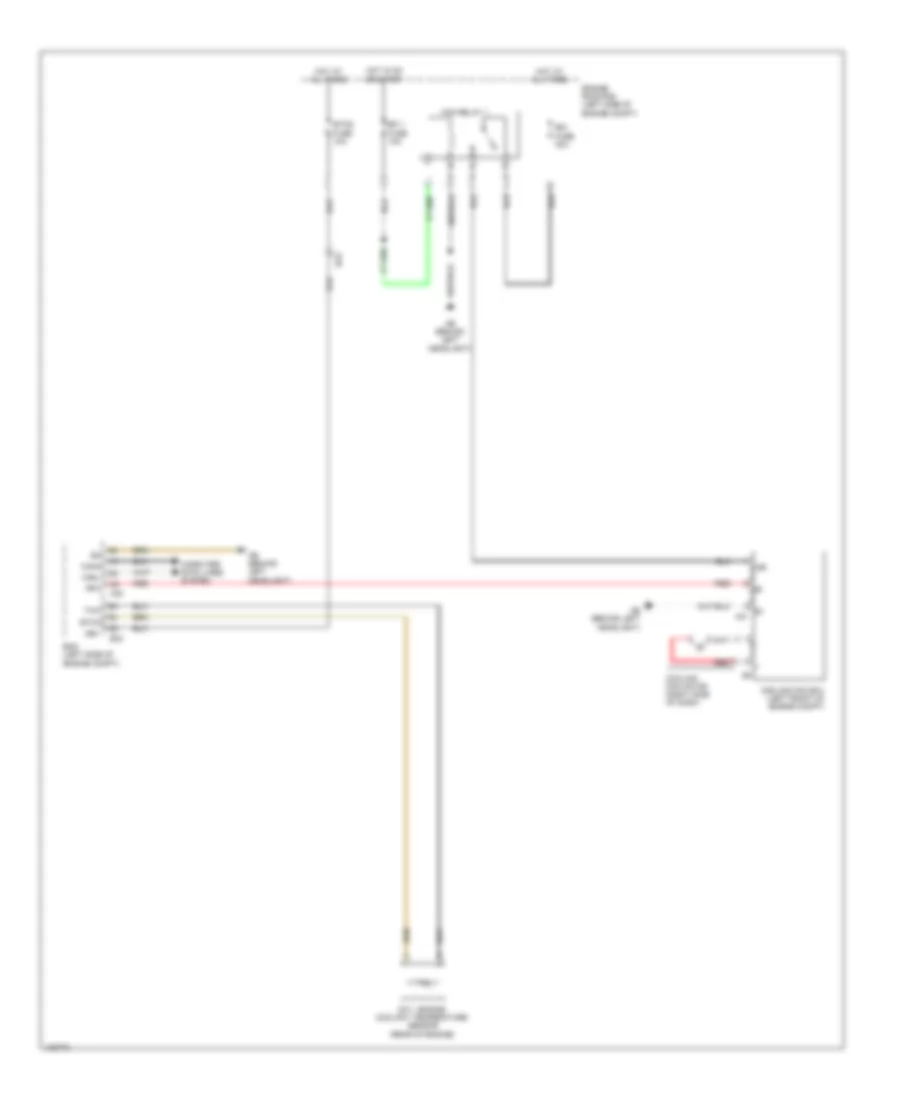
Body Control Modules Wiring Diagram (2 of 2) for Toyota Corolla LE Eco 2014
List of elements for Body Control Modules Wiring Diagram (2 of 2) for Toyota Corolla LE Eco 2014:
- (left side of engine compt)
- (right end of dash) can junction connector 2
- (right front of engine compt) brake actuator assembly
- A/c amplifier assembly (center of dash)
- A40
- Ae4
- Air bag sensor assembly (front of center console)
- Anti-theft system
- Automatic a/c
- Can junction connector 3 (center of dash)
- Canh
- Canl
- Certification ecu (w/ smart key system) (right side of dash)
- Combination meter assembly
- Data link connector 3 (left side of dash)
- Dumy
- E14
- E29
- E32
- E37
- E40
- E43
- E59
- Ecm
- Hcty
- Ind
- Interior lights system
- Main body ecu (left end of dash)
- Manual a/c
- Pnk
- Power steering ecu assembly (behind instrument cluster)
- Radio & display receiver assembly (w/ radio & display receiver type) navigation receiver assembly (w/ navigation receiver type) e67
- Red
- Steering sensor (w/ vsc) (steering column assembly)
- W/ navigation receiver type
- W/ radio & display receiver type
COMPUTER DATA LINES
Computer Data Lines Wiring Diagram (1 of 2) for Toyota Corolla LE Eco 2014
List of elements for Computer Data Lines Wiring Diagram (1 of 2) for Toyota Corolla LE Eco 2014:
- (behind instrument cluster) power steering ecu assembly
- (right "c" pillar) lc
- Ae4
- Air bag sensor assembly (front of center console)
- Ba1
- Bat
- Bb (top of engine)
- Can j/c 3 (center of dash)
- Canh
- Canl
- Certification ecu (right side of dash)
- Combination meter assembly
- D17
- D20
- D21
- Data link connector 3 (left side of dash)
- Driver's side j/b assembly (left end of dash)
- E14
- E29
- E40
- E43
- E59
- E67
- Eb (center of dash)
- El2
- Hot at all times
- Id code box (center of dash)
- Limit switch
- Lin
- Lin1
- Ls+
- Ls-
- Ls2
- Navigation receiver assembly (w/ navigation) radio & display receiver assembly (w/o navigation)
- Obd fuse 7.5a
- Op4
- Pnk
- Red
- Right front seat inner belt assembly
- Sil
- Steering lock actuator assembly (steering column)
- Tac
- Tmmc made w/ occupant detection ecu
- Tmmms made w/ occupant detection ecu
- W/ navigation
- W/o navigation
Computer Data Lines Wiring Diagram (2 of 2) for Toyota Corolla LE Eco 2014
List of elements for Computer Data Lines Wiring Diagram (2 of 2) for Toyota Corolla LE Eco 2014:
- (center of dash) transponder key ecu assembly
- (left end of dash) (w/ valvematic) can j/c 1
- (left front of engine compt) generator control ecu assembly
- (left side of engine compt) ecm
- (rear of engine) continuously variable valve lift controller assembly
- (right end of dash) can j/c 2
- (under front passenger's seat) occupant detection ecu
- A/c amplifier (center of dash)
- A/c control assembly
- A35
- A36
- A37
- A40
- Ae4
- Automatic a/c
- B33
- B37
- Ba1
- Ba2
- Brake actuator assembly (right front of engine compt)
- C52
- C53
- Ca3n
- Ca3p
- Can+
- Can-
- Canh
- Canl
- Dia
- Driver's side j/b assembly (left end of dash)
- E31
- E37
- El2
- Generator (w/ regulator assembly)
- He1
- Left front power window regulator motor assembly
- Lin
- Lin1
- Lin2
- Ls2
- Main body ecu
- Manual a/c
- Mpx1
- Oe1
- Pnk
- Red
- Sliding roof control ecu (sliding roof drive gear sub-assembly)
- Steering sensor (w/ vsc) (steering column assembly)
- Tach
- W/ occupant detection ecu
- W/ smart key system
- W/o occupant detection ecu
- W/o smart key system
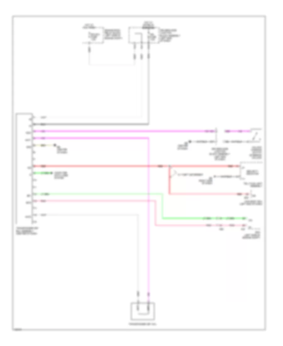
COOLING FAN
Cooling Fan Wiring Diagram for Toyota Corolla LE Eco 2014
List of elements for Cooling Fan Wiring Diagram for Toyota Corolla LE Eco 2014:
- +b1
- +bm
- A40
- Ab (behind left headlight)
- B33
- Ba2
- Canh
- Canl
- Computer data lines system
- Cooling fan ecu (left front of engine compt)
- Cooling fan motor (right side of dash)
- E.f.i. engine coolant temperature sensor (rear of engine)
- E1 a31
- Ecm (left side of engine compt)
- Efi 1 fuse 10a
- Engine room r/b (left side of engine compt)
- Etcs fuse 10a
- Ethw
- Fan relay 1
- Hot at all times
- Hot in on or start
- Rdi fuse 30a
- Red
- Rfc
- Thw
CRUISE CONTROL
Cruise Control Wiring Diagram (1 of 2) for Toyota Corolla LE Eco 2014
List of elements for Cruise Control Wiring Diagram (1 of 2) for Toyota Corolla LE Eco 2014:
- (center console)
- +res
- -set
- A/t
- A40
- A56
- Ab (behind left headlight)
- Accelerator pedal sensor assembly (base of accelerator pedal)
- Ae2
- Ae3
- Ae4
- B33
- Ba (top of engine)
- Ba1
- Ba2
- Batt
- Cancel
- Canh
- Canl
- Ccs
- Computer data lines system
- Cruise control main switch
- Cruise control switch
- Cruise control switch wire
- Cvt
- Diode (back-up light)
- Driver's side j/b assembly (left end of dash)
- Ecc
- Ecm (left side of engine compt)
- Ecu- ig 2 fuse 10a
- Efi 1 fuse 10a
- Efi main fuse 20a
- Efi main relay
- Engine room r/b (left side of engine compt)
- Epa
- Epa2
- Eta
- Ge01
- Hot at all times
- Hot in on or start
- Igsw
- J/c a38
- Mrel
- On-off
- Park/neutral position switch (left side of transaxle)
- Pnk
- Red
- Shift position indicator
- Spd
- Spiral cable sub-assembly (steering column)
- St1-
- Stp
- Throttle body assembly (air intake manifold opening)
- Transmission floor shift assembly
- Vcp2
- Vcpa
- Vcta
- Vpa
- Vpa2
- Vta
- Vta1
- Vta2
Cruise Control Wiring Diagram (2 of 2) for Toyota Corolla LE Eco 2014
List of elements for Cruise Control Wiring Diagram (2 of 2) for Toyota Corolla LE Eco 2014:
- +bs
- 5v +b
- 5v ic
- A18
- A19
- A35
- A36
- A37
- A40
- A44
- A48
- Abs 2 fuse 30a
- Ac (behind right headlight)
- Ae3
- Ae6
- Al1
- Brake actuator assembly (right front of engine compt)
- C55
- Can i/f
- Canh
- Canl
- Chk
- Combination meter assembly
- Computer data lines system
- Cpu
- Cruise ind
- D28
- D40
- Driver display
- Driver's side junction block assembly (left end of dash)
- E43
- Ecu-b fuse 7.5a
- Ed (right side of dash)
- El2
- Engine room relay block (left side of engine compt)
- Fl+
- Fl-
- Fr+
- Fr-
- Gnd1
- Gnd2
- Hot at all times
- Hot in on or start
- I/f
- Ig+
- Ign fuse 7.5a
- Led driver
- Left front speed sensor (left front wheel hub assembly)
- Left rear speed sensor (left rear wheel hub assembly)
- Malfunction ind lamp
- Meter fuse 5a
- Pnk
- Red
- Right front speed sensor (right front wheel hub assembly)
- Right rear speed sensor (right rear wheel hub assembly)
- Rl+
- Rl-
- Rr+
- Rr-
- Set ind
- Sp1
- Stop fuse 10a
- Stop light switch (top of brake pedal assembly)
- Stp
- W/ vsc
- W/o vsc
- Hl1
- Jl1
DEFOGGERS
Defoggers Wiring Diagram for Toyota Corolla LE Eco 2014
List of elements for Defoggers Wiring Diagram for Toyota Corolla LE Eco 2014:
- A/c amplifier assembly (automatic a/c) (center of dash)
- A/c control assembly (automatic a/c)
- A43
- A46
- Ab (behind left headlight)
- Ae6
- Al2
- Automatic a/c
- D35
- D36
- D42
- D45
- Def fuse 50a
- Def relay
- Driver's side j/b assembly (left end of dash)
- E37
- Ea (left kick panel)
- Eb (center of dash)
- Ec (right kick panel)
- Ed (right side of dash)
- Engine room r/b (left side of engine compt)
- Ge1
- Gnd
- He1
- Heater control sub-assembly 2 (manual a/c) (center of dash)
- Hot at all times
- Hot w/ ig1 1 relay energized
- Htr-ig fuse 10a
- Ig+
- L27
- Left outer rear view mirror assembly
- Lin1
- Manual a/c
- Mir htr fuse 10a
- Mirror heater
- Noise filter (radio setting condenser) (left "d" pillar)
- Qa (right "c" pillar)
- Rdef
- Rdfg
- Rear window defogger (back window glass)
- Rear window defogger switch
- Right outer rear view mirror assembly
- Timer circuit
- W/ mirror heater
ELECTRONIC POWER STEERING
Electronic Power Steering Wiring Diagram for Toyota Corolla LE Eco 2014
List of elements for Electronic Power Steering Wiring Diagram for Toyota Corolla LE Eco 2014:
- (left end of dash) ae
- 5v +b
- 5v ic
- A25
- A44
- Bat
- C18
- C55
- Can i/f
- Canh
- Canl
- Combination meter assembly
- Computer data lines system
- Cpu
- D22
- D30
- D40
- Driver's side junction block assembly (left end of dash)
- E40
- E43
- Ecu-b 2 fuse 7.5a
- Ecu-ig 3 fuse 7.5a
- Ecu-ig 4 fuse 5a
- Ed (right side of dash)
- Engine room relay block (left side of engine compt)
- Eps fuse 80a
- Ess
- Hot at all times
- Hot w/ ig1 relay energized
- Hot w/ ig2 relay energized
- Led driver
- Meter fuse 5a
- Pgnd
- Pig
- Pnk
- Power steering ecu (behind instrument cluster)
- Power steering ind
- Power steering motor
- Power steering motor assembly (left end of dash)
- Power steering torque sensor
- Power steering torque sensor (steering column assembly)
- Red
- Steering sensor (steering column assembly)
- Trq1
- Trq2
- Trqg
- Trqv
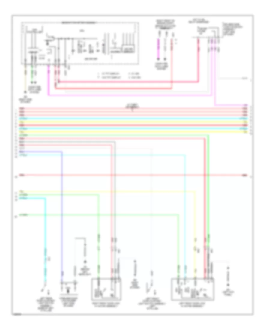
ENGINE PERFORMANCE
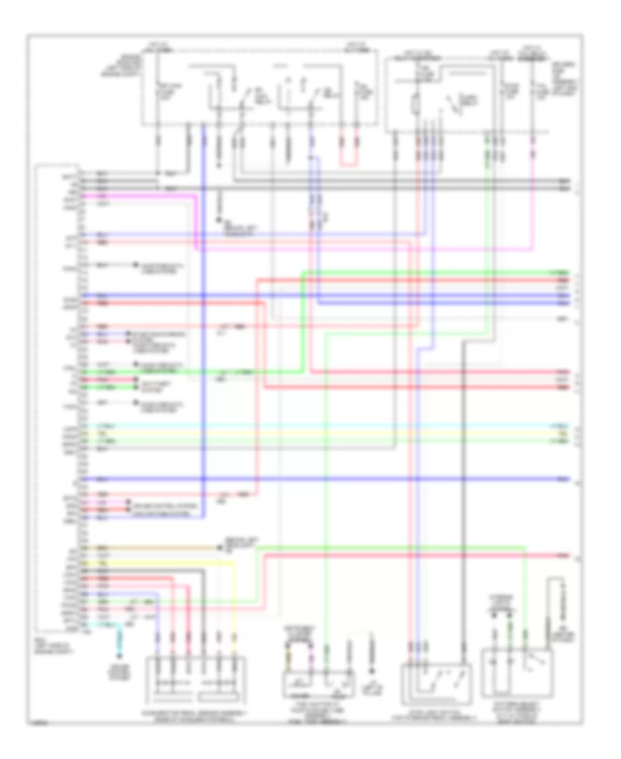
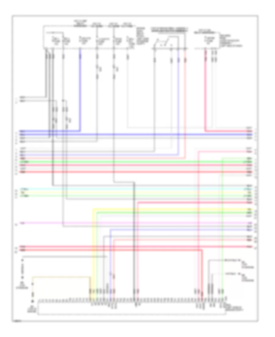
1.8L
1.8L, Engine Performance Wiring Diagram, with Dual VVT-I (1 of 7) for Toyota Corolla LE Eco 2014
List of elements for 1.8L, Engine Performance Wiring Diagram, with Dual VVT-I (1 of 7) for Toyota Corolla LE Eco 2014:
- (behind left headlight) ab
- +b2
- A14
- A19
- A35
- A36
- A37
- A40
- Ab (behind left headlight)
- Accelerator pedal sensor assembly (base of accelerator pedal)
- Ae2
- Ae3
- Al1
- Anti-theft system
- Ba2
- Batt
- C/opn relay
- Canh
- Canl
- Ccs
- Computer data lines system
- Cooling fans system
- Cruise control system
- Driver's side j/b assembly (left end of dash)
- E36
- Eb (center of dash)
- Ecm (left side of engine compt)
- Efi main fuse 20a
- Efi main relay
- Els1
- Els2
- Engine room r/b (left side of engine compt)
- Epa
- Epa2
- Eppm
- Fuel suction w/ pump & gauge tube assembly (fuel tank assembly)
- Gauge
- Hot at all times
- Hot w/ ig2 relay energized
- Hot w/ tail relay energized
- Ig2 fuse 15a
- Ig2 relay
- Ign fuse 7.5a
- Igsw
- Imi
- Imo
- Instrument cluster system
- Interior lights system
- La (left ''b'' pillar)
- Mpmp
- Mrel
- Pattern select switch assembly (cvt w/ paddle shift switch)
- Pnk
- Ppmp
- Pump
- Pwms
- Red
- Rfc
- Sdsw
- Sftd
- Sftu
- Spd
- St1-
- Sta
- Starting/charging system computer data lines system
- Stop fuse 10a
- Stop light switch (top of brake pedal assembly)
- Stp
- Tach
- Tail fuse 10a
- Vcp2
- Vcpa
- Vcpp
- Vpa
- Vpa2
- Vpmp
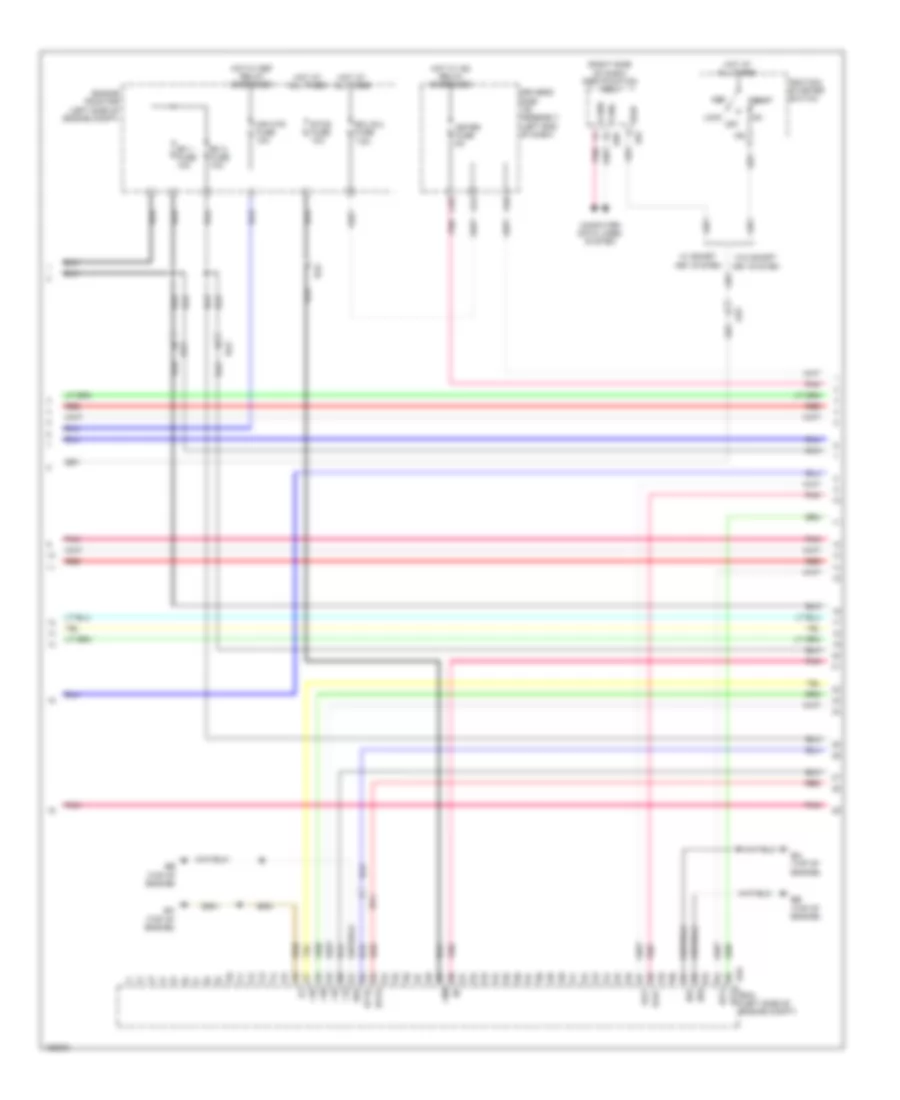
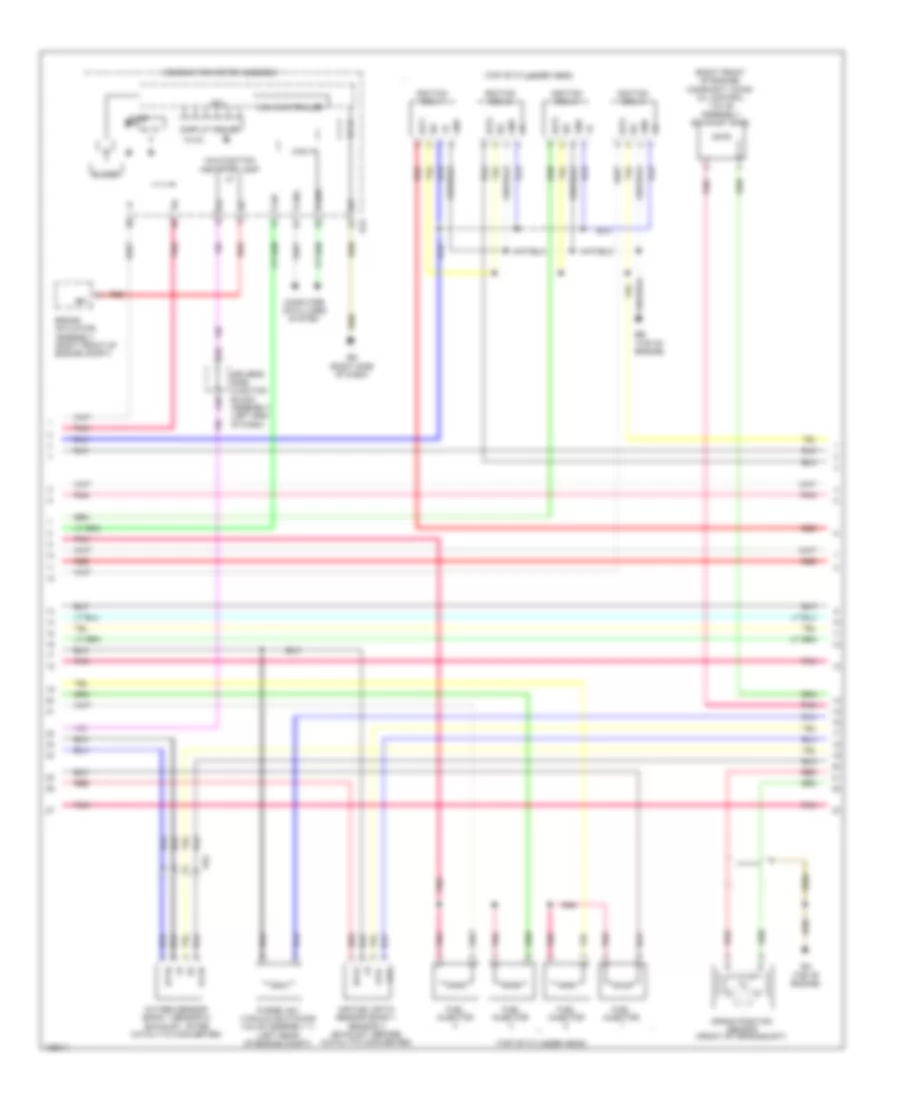
1.8L, Engine Performance Wiring Diagram, with Dual VVT-I (2 of 7) for Toyota Corolla LE Eco 2014
List of elements for 1.8L, Engine Performance Wiring Diagram, with Dual VVT-I (2 of 7) for Toyota Corolla LE Eco 2014:
- (right side of dash) certification ecu
- +10
- +20
- +30
- +40
- +bm
- A44
- Acc
- Ae3
- B33
- Ba (top of engine)
- Ba1
- Ba2
- Bb (top of engine)
- C55
- Canh
- Canl
- Computer data lines system
- D40
- Driver's side j/b assembly (left end of dash)
- E01
- E02
- E04
- E57
- E59
- Ecm (left side of engine compt)
- Ecu b 2 fuse 7.5a
- Efi 1 fuse 10a
- Efi 2 fuse 10a
- Engine room r/b (left side of engine compt)
- Etcs fuse 10a
- Ha1a
- Hot at all times
- Hot w/ def relay energized
- Hot w/ ig2 relay energized
- Ht1b
- Ig2
- Ig2d
- Ignition/ starter switch
- Igt3
- Igt4
- Lock off
- Meter fuse 5a
- Mir htr fuse 10a
- Pnk
- Red
- Slu+
- Slu-
- Start
- W/ smart key system
- W/o smart key system
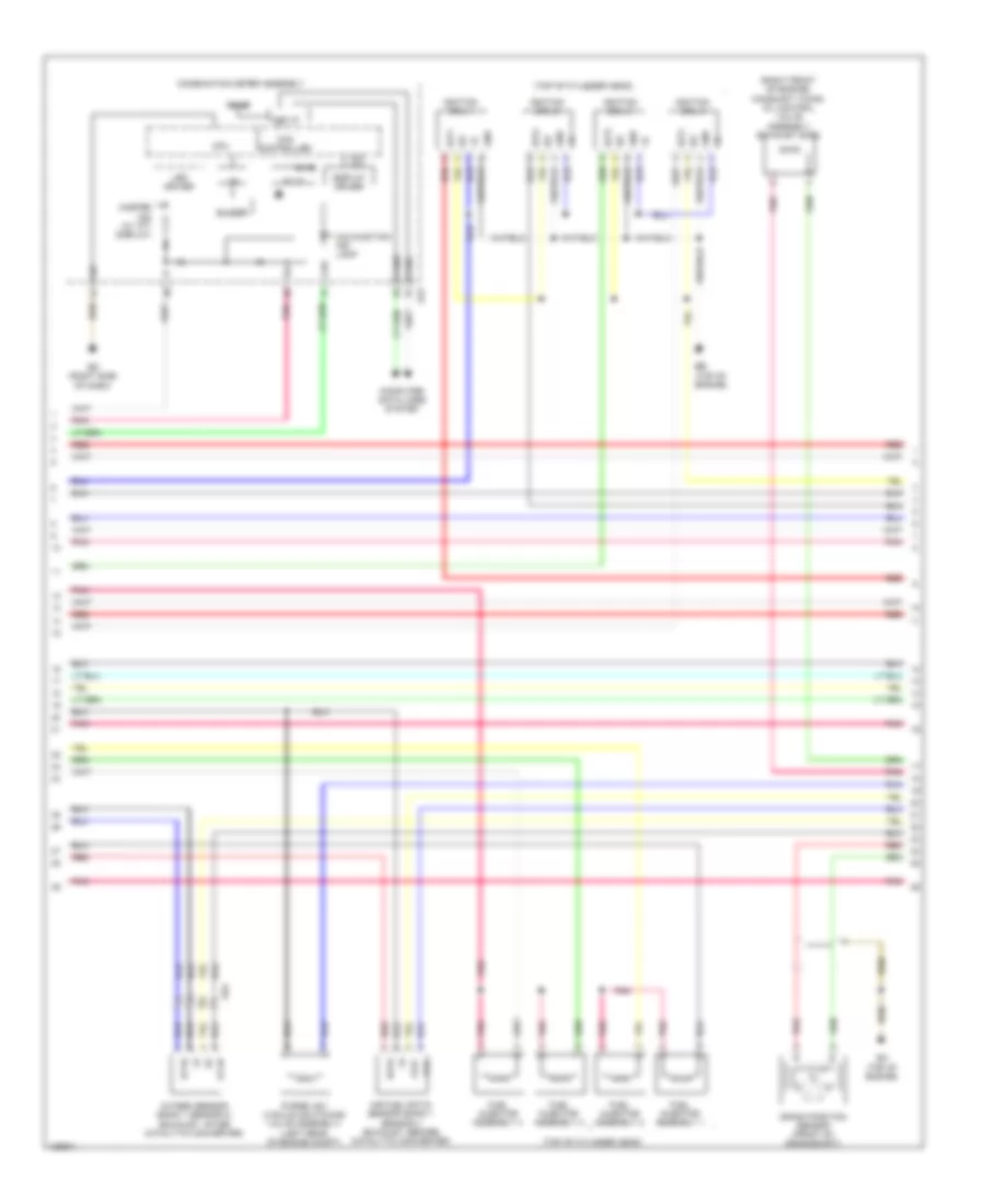
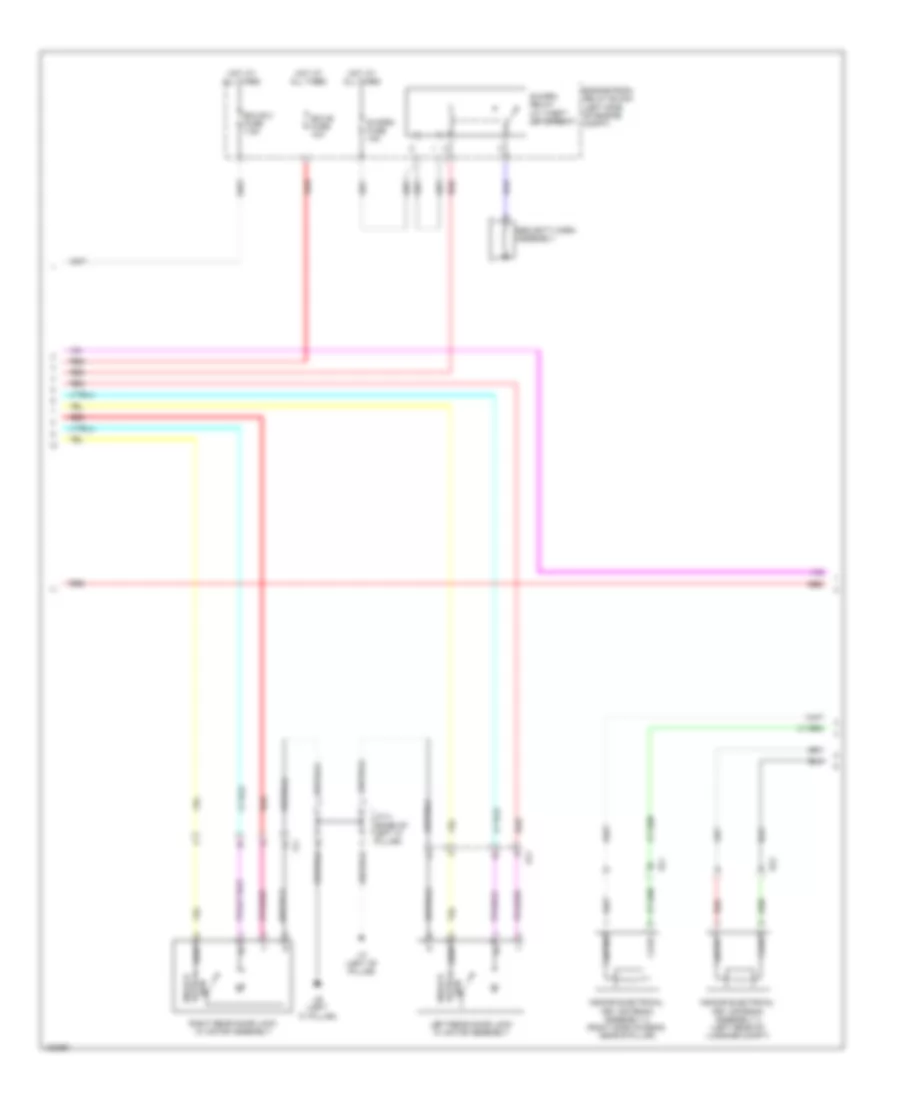
1.8L, Engine Performance Wiring Diagram, with Dual VVT-I (3 of 7) for Toyota Corolla LE Eco 2014
List of elements for 1.8L, Engine Performance Wiring Diagram, with Dual VVT-I (3 of 7) for Toyota Corolla LE Eco 2014:
- (right front of engine) camshaft timing oil control valve assembly (exhaust side)
- (top of cylinder head)
- 5v ic
- 5v+b
- A1a+
- A1a-
- Ae4
- Air fuel ratio sensor (bank 1 sensor 1) (exhaust, before catalytic converter)
- Ba (top of engine)
- Bb (top of engine)
- Buzzer
- Can controller
- Can i/f
- Canh
- Canl
- Chk
- Combination meter assembly
- Computer data lines system
- Cpu
- Crank position sensor (front of crankshaft)
- Display driver
- E43
- Ed (right side of dash)
- Fuel injector assembly 1
- Fuel injector assembly 2
- Fuel injector assembly 3
- Fuel injector assembly 4
- Gnd
- Ha1a
- Ht1b
- I/f
- Ig+
- Igf
- Ignition coil 1
- Ignition coil 2
- Ignition coil 3
- Ignition coil 4
- Igt1
- Igt2
- Igt3
- Igt4
- Led driver
- Malfunction ind lamp
- Master ind (w/ tft display)
- Ox1b
- Oxygen sensor (bank 1 sensor 2) (exhaust, after catalytic converter)
- Pnk
- Purge vsv (vacuum switching valve assembly) (left rear of engine compt)
- Red
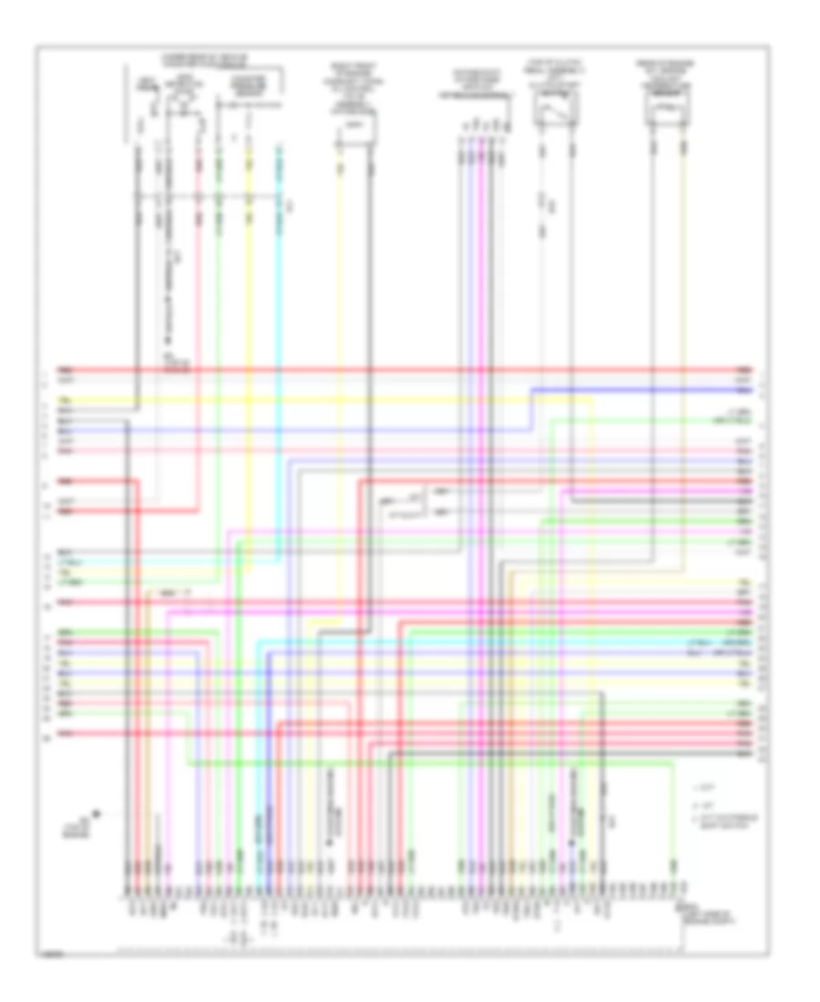
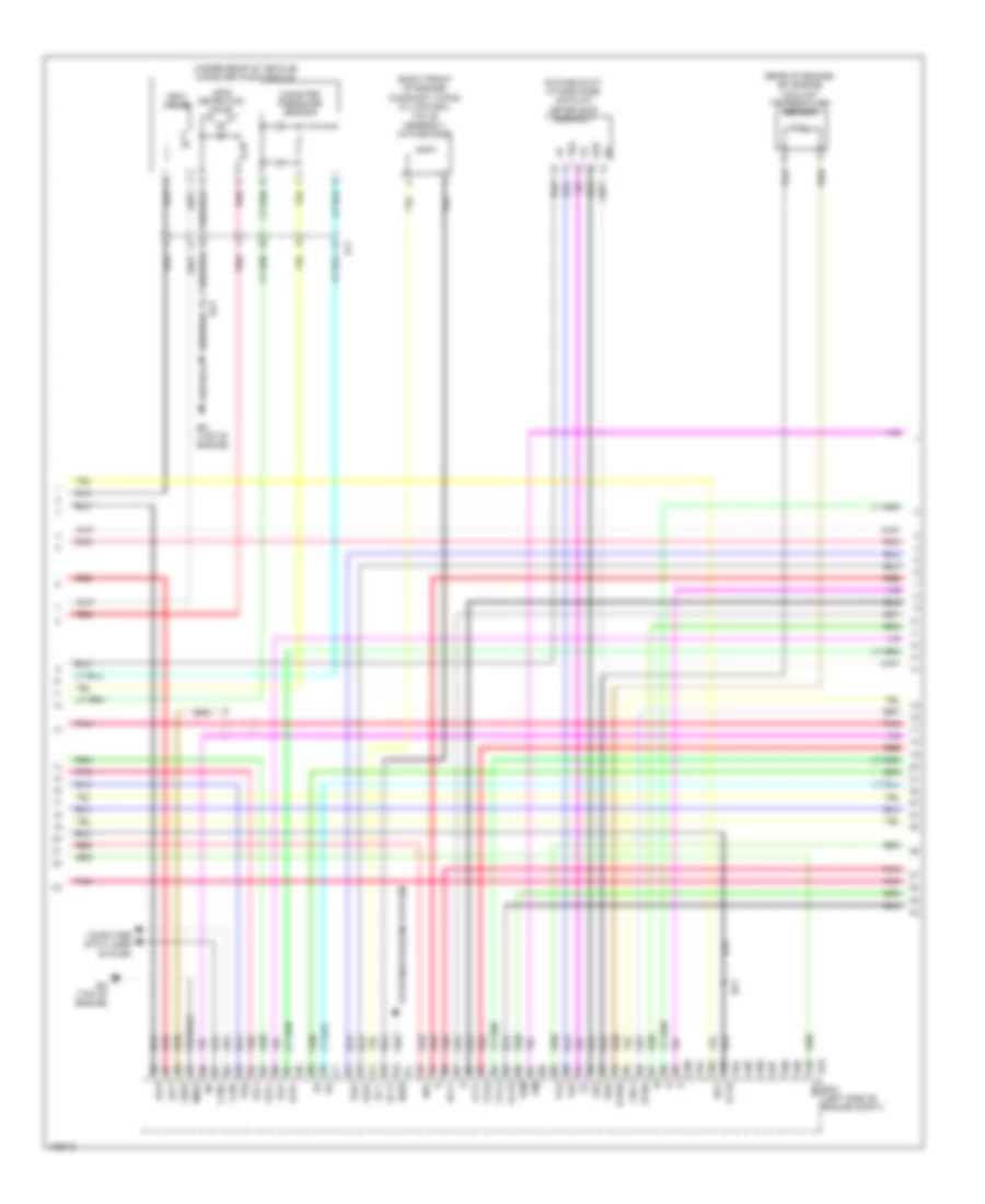
1.8L, Engine Performance Wiring Diagram, with Dual VVT-I (4 of 7) for Toyota Corolla LE Eco 2014
List of elements for 1.8L, Engine Performance Wiring Diagram, with Dual VVT-I (4 of 7) for Toyota Corolla LE Eco 2014:
- (intake duct) intake mass air flow meter sub-assembly
- (rear of engine) e.f.i engine coolant temperature sensor
- (right front of engine) camshaft timing oil control valve assembly (intake side)
- (top of clutch pedal assembly) (m/t) clutch start switch
- (under rear of vehicle) canister pump module
- A/t
- A/t & cvt
- Al1
- Alt
- B33
- Ba (top of engine)
- Ba1
- Ba2
- Canister pressure sensor
- Cvt
- Cvt w/o paddle
- E2g
- Ecm (left side of engine compt)
- Etho
- Ethw
- Ev1+
- Ge01
- Igf1
- Igt1
- Igt2
- Leak detection pump
- M/t
- Me01
- Ne+
- Ne-
- Nsw
- Oc1+
- Oc1-
- Oe1+
- Oe1-
- Ox1b
- Pnk
- Prg
- Pto
- Red
- Shift switch
- Slp+
- Slp-
- Sls+
- Sls-
- Slt+
- Slt-
- System starting/charging
- Tha
- Tho1
- Thw
- Vent valve
- Vta1
- Vta2
- Vv1+
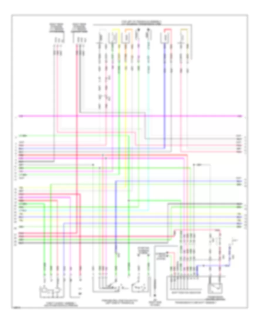
1.8L, Engine Performance Wiring Diagram, with Dual VVT-I (5 of 7) for Toyota Corolla LE Eco 2014
List of elements for 1.8L, Engine Performance Wiring Diagram, with Dual VVT-I (5 of 7) for Toyota Corolla LE Eco 2014:
- (left side of transaxle) (a/t) electronically controlled transmission solenoid (transmission wire)
- (top left of transaxle assembly) (cvt) cvt solenoid (transmission wire)
- A/t
- Ae4
- At3
- Ba1
- Ba2
- Cvt
- Cvt w/o paddle shift switch
- Ed (right side of dash)
- Ill+
- Ill-
- Interior lights system
- J/c a38
- Nssd
- Ntb
- Nto
- Park/neutral position switch (left side of transaxle)
- Pnk
- Red
- Shift position indicator
- Slp+
- Slp-
- Sls+
- Sls-
- Slt+
- Slt-
- Slu+
- Slu-
- Starting/ charging system
- Tho
- Throttle body assembly (air intake manifold opening)
- Transmission control switch (w/o paddle shift switch)
- Transmission floor shift assembly
- Vta
- Vta2
1.8L, Engine Performance Wiring Diagram, with Dual VVT-I (6 of 7) for Toyota Corolla LE Eco 2014
List of elements for 1.8L, Engine Performance Wiring Diagram, with Dual VVT-I (6 of 7) for Toyota Corolla LE Eco 2014:
- (center console) (cvt & a/t) diode (backup light)
- (left side of engine block) knock control sensor (bank 1)
- (on transmission case) (cvt) oil pressure sensor
- (right rear of engine) vvt sensor (intake side)
- A/t
- A45
- A56
- Acc fuse 7.5a
- Ae2
- Ba (top of engine)
- Bd1
- Cvt
- Driver's side j/b assembly (left end of dash)
- Ecu-ig 2 fuse 10a
- Hot w/ acc relay energized
- Hot w/ ig1 1 relay energized
- J/c a38
- Nca
- Pnk
- Pto
- Red
- Transmission revolution sensor (primary) (left side of transaxle case)
- Transmission revolution sensor (secondary) (cvt) (right side of transmission case)
- Transmission revolution sensor (turbine)
- Vc2
- Vve+
- Vve-
- Vvi+
- Vvi-
- Vvt sensor (exhaust side) (right rear of engine)
1.8L, Engine Performance Wiring Diagram, with Dual VVT-I (7 of 7) for Toyota Corolla LE Eco 2014
List of elements for 1.8L, Engine Performance Wiring Diagram, with Dual VVT-I (7 of 7) for Toyota Corolla LE Eco 2014:
- (left side of engine compt) ecm
- A/t
- A1a+
- A1a-
- A20
- Ae2
- Ae3
- B33
- Ba (top of engine)
- Ba1
- C39
- Cvt
- Down
- Driver's side j/b assembly (left end of dash)
- Eb (center of dash)
- Ecta
- Ecu-ig 3 fuse 7.5a
- Eknk
- Epto
- Eta
- Etha
- Ev1-
- Ex1b
- Hot w/ ig1 1 relay energized
- J/c a38
- Knk1
- Left steering pad switch assembly
- Nin+
- Nin-
- Notb
- Noto
- Nt+
- Nt-
- Ntb
- Nto
- Pnk
- Red
- Right steering pad switch assembly
- Sftd
- Sftu
- Spiral cable sub-assembly (steering column)
- Steering pad switch assembly
- Transmission control switch (transmission floor shift assembly) (cvt w/ paddle shift switch) (under center console)
- Transmission shift switch assembly
- Vce1
- Vcpt
- Vcv1
- Vv1-
- W/ cruise control
- Z10
1.8L, Engine Performance Wiring Diagram, with Valvematic (1 of 6) for Toyota Corolla LE Eco 2014
List of elements for 1.8L, Engine Performance Wiring Diagram, with Valvematic (1 of 6) for Toyota Corolla LE Eco 2014:
- (behind left headlight) ab
- +b2
- A19
- A35
- A36
- A37
- A40
- Ab (behind left headlight)
- Accelerator pedal sensor assembly (base of accelerator pedal)
- Ae3
- Al1
- Al2
- Anti-theft system
- Ba2
- Batt
- Can+
- Can-
- Canh
- Canl
- Ccs
- Computer data lines system
- Continuously variable valve lift controller assembly (rear of engine compt)
- Cooling fans system
- Cruise control system
- Door locks system
- Driver's side junction block assembly (left end of dash)
- Ecm (left side of engine compt)
- Efi- main relay
- Efi-main fuse 20a
- Els1
- Els2
- Engine room relay block (left side of engine compt)
- Epa
- Epa2
- Eppm
- Fp-
- Fpc
- Fuel pump control ecu assembly (left rear luggage compt)
- Fuel suction w/ pump & gauge tube assembly (fuel tank assembly)
- Gauge
- Hall ic
- Hot at all times
- Hot w/ ig2 relay energized
- Hot w/ tail relay energized
- Ign fuse 7.5a
- Igsw
- Igt/ inj relay
- Imi
- Imo
- Inj fuse 15a
- Instrument cluster system
- Mpmp
- Mrel
- Neo
- Pnk
- Ppmp
- Pump
- Red
- Rfc
- Sdsw
- Sdwn
- Spd
- St1-
- Sta
- Starting/charging system computer data lines system
- Stop fuse 10a
- Stp
- Tach
- Tail fuse 10a
- Vcp2
- Vcpa
- Vcpp
- Vpa
- Vpa2
- Vpmp
1.8L, Engine Performance Wiring Diagram, with Valvematic (2 of 6) for Toyota Corolla LE Eco 2014
List of elements for 1.8L, Engine Performance Wiring Diagram, with Valvematic (2 of 6) for Toyota Corolla LE Eco 2014:
- (top of brake pedal assembly) stop light switch assembly
- +bm
- A44
- B33
- Ba (top of engine)
- Ba1
- Ba2
- Ba3
- Bb (top of engine)
- C55
- D40
- Driver's side junction block assembly (left end of dash)
- E01
- E02
- E04
- Ecm (left side of engine compt)
- Ecu- b 2 fuse 7.5a
- Efi 1 fuse 10a
- Efi 2 fuse 10a
- Engine room relay block (left side of engine compt)
- Etcs fuse 10a
- Ha1a
- Hot at all times
- Hot w/ def relay energized
- Hot w/ ig2 relay energized
- Ht1b
- Igt3
- Igt4
- Meter fuse 5a
- Mir htr fuse 10a
- Pnk
- Red
- Sdwn
- Slu+
- Slu-
- Vlvmatic fuse 30a
1.8L, Engine Performance Wiring Diagram, with Valvematic (3 of 6) for Toyota Corolla LE Eco 2014
List of elements for 1.8L, Engine Performance Wiring Diagram, with Valvematic (3 of 6) for Toyota Corolla LE Eco 2014:
- (right front of engine) camshaft timing oil control valve assembly (exhaust side)
- (top of cylinder head)
- 5v ic
- 5v+b
- A1a+
- A1a-
- A48
- Ae4
- Air fuel ratio sensor (bank 1 sensor 1) (exhaust, before catalytic converter)
- Ba (top of engine)
- Bb (top of engine)
- Brake actuator assembly (right front of engine compt)
- Buzzer
- Can controller
- Can i/f
- Canh
- Canl
- Chk
- Combination meter assembly
- Computer data lines system
- Cpu
- Crank position sensor (front of crankshaft)
- D28
- Display driver
- Driver's side junction block assembly (left end of dash)
- E43
- Ed (right side of dash)
- Fuel injector
- Gnd
- Ha1a
- Ht1b
- I/f
- Ig+
- Igf
- Ignition coil 1
- Ignition coil 2
- Ignition coil 3
- Ignition coil 4
- Igt1
- Igt2
- Igt3
- Igt4
- Malfunction indicator lamp
- Ox1b
- Oxygen sensor (bank 1 sensor 2) (exhaust, after catalytic converter)
- Pnk
- Purge vsv (vacuum switching valve assembly 1) (left rear of engine compt)
- Red
- Sp1
1.8L, Engine Performance Wiring Diagram, with Valvematic (4 of 6) for Toyota Corolla LE Eco 2014
List of elements for 1.8L, Engine Performance Wiring Diagram, with Valvematic (4 of 6) for Toyota Corolla LE Eco 2014:
- (intake duct) intake mass air flow meter sub- assembly
- (rear of engine) efi engine coolant temperature sensor
- (right front of engine) camshaft timing oil control valve assembly (intake side)
- (under rear of vehicle) canister pump module
- Al1
- B33
- Ba (top of engine)
- Ba1
- Can+
- Can-
- Canister pressure sensor
- Computer data lines system
- E2g
- Ecm (left side of engine compt)
- Etho
- Ethw
- Ev1+
- Ge01
- Igf1
- Igt1
- Igt2
- Leak detection pump
- Me01
- Ne+
- Ne-
- Nsw
- Oc1+
- Oc1-
- Oe1+
- Oe1-
- Ox1b
- Pim
- Pnk
- Prg
- Pto
- Red
- Slp+
- Slp-
- Sls+
- Sls-
- Starting/charging system
- Tha
- Tho1
- Thw
- Vcvs
- Vent valve
- Vsm
- Vta1
- Vta2
- Vv1+
1.8L, Engine Performance Wiring Diagram, with Valvematic (5 of 6) for Toyota Corolla LE Eco 2014
List of elements for 1.8L, Engine Performance Wiring Diagram, with Valvematic (5 of 6) for Toyota Corolla LE Eco 2014:
- (right rear of engine) vvt sensor (exhaust side)
- (right rear of engine) vvt sensor (intake side)
- (top left of transaxle assembly) cvt solenoid (transmission wire)
- Ae2
- Ae4
- At3
- Ba1
- Ba2
- D n
- Ed (right side of dash)
- Ill+
- Ill-
- Interior lights system
- J/c 1
- Nssd
- Ntb
- Nto
- Park/neutral position switch (left side of transaxle)
- Pnk
- R n
- Red
- Shift position indicator
- Slp+
- Slp-
- Sls+
- Sls-
- Slu+
- Slu-
- Starting/ charging system
- Tho
- Throttle body assembly (air intake manifold opening)
- Transmission control switch
- Transmission floor shift assembly
- Vc2
- Vta
- Vta2
- Vv1+
- Vve+
- Vve-
- Vvi-
1.8L, Engine Performance Wiring Diagram, with Valvematic (6 of 6) for Toyota Corolla LE Eco 2014
List of elements for 1.8L, Engine Performance Wiring Diagram, with Valvematic (6 of 6) for Toyota Corolla LE Eco 2014:
- (left rear of engine) e.f.i vacuum sensor assembly
- (left side of engine block) knock control sensor (bank 1)
- (on transmission case) oil pressure sensor
- A1a+
- A1a-
- A45
- A56
- Acc fuse 7.5a
- Ae2
- B33
- Ba (top of engine)
- Ba1
- Bd1
- Diode (backup light) (center console)
- Driver's side junction block assembly (left end of dash)
- E2vs
- Ecm (left side of engine compt)
- Ecu- ig 2 fuse 10a
- Eknk
- Epim
- Epto
- Eta
- Etha
- Ethe
- Ev1-
- Ex1b
- Gnd
- Hot w/ acc relay energized
- Hot w/ ig1 1 relay energized
- J/c a38
- Knk1
- Nca
- Nin+
- Nin-
- Notb
- Noto
- Ntb
- Nto
- Oil temperature sensor (front of engine)
- Pim
- Pnk
- Pto
- Red
- Theo
- Transmission revolution sensor (primary) (left side of transaxle case)
- Transmission revolution sensor (secondary) (right side of transmission case)
- Valve event angle control shaft monitor sensor (crank position sensor 1) (rear of engine)
- Vcc
- Vce1
- Vcpm
- Vcpt
- Vcta
- Vcv1
- Vout
- Vv1-
EXTERIOR LIGHTS
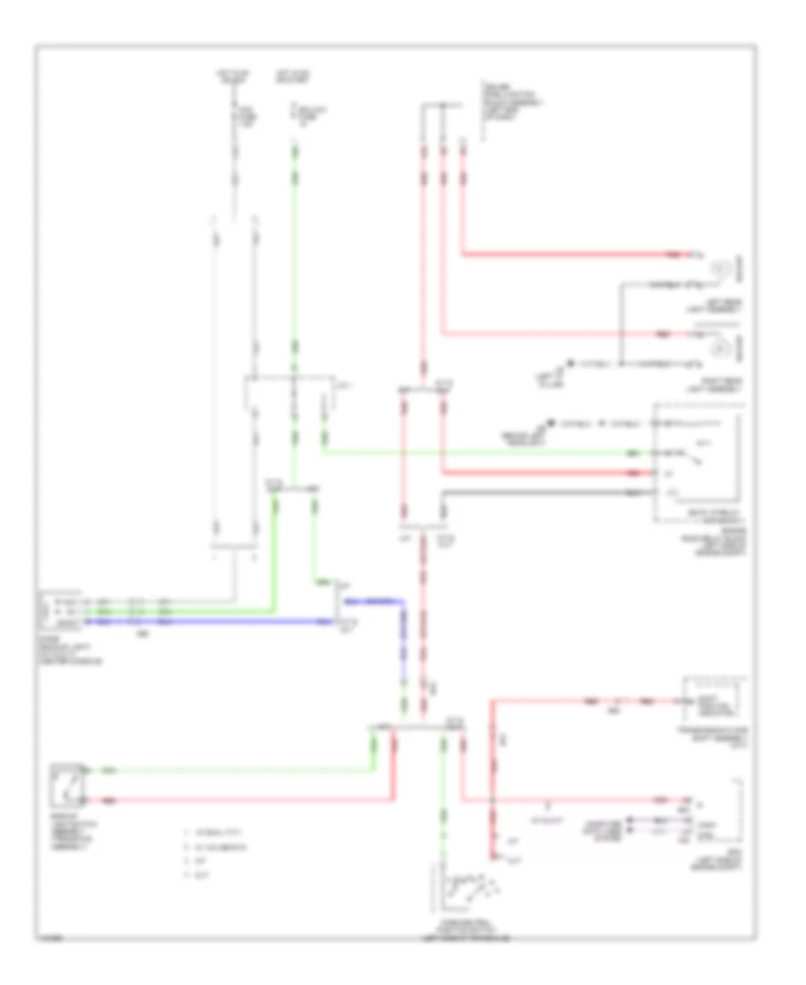
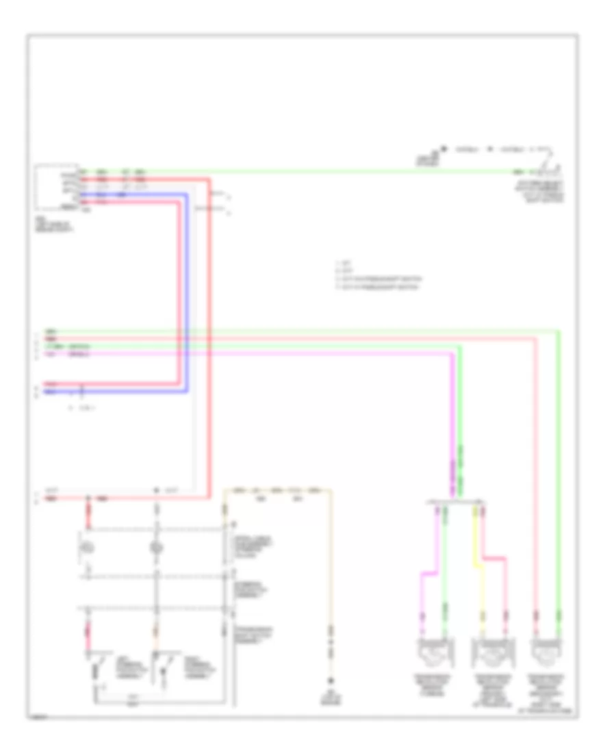
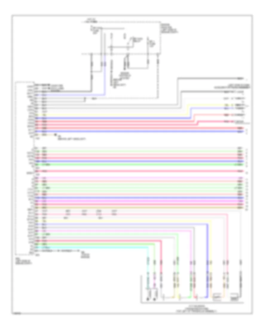
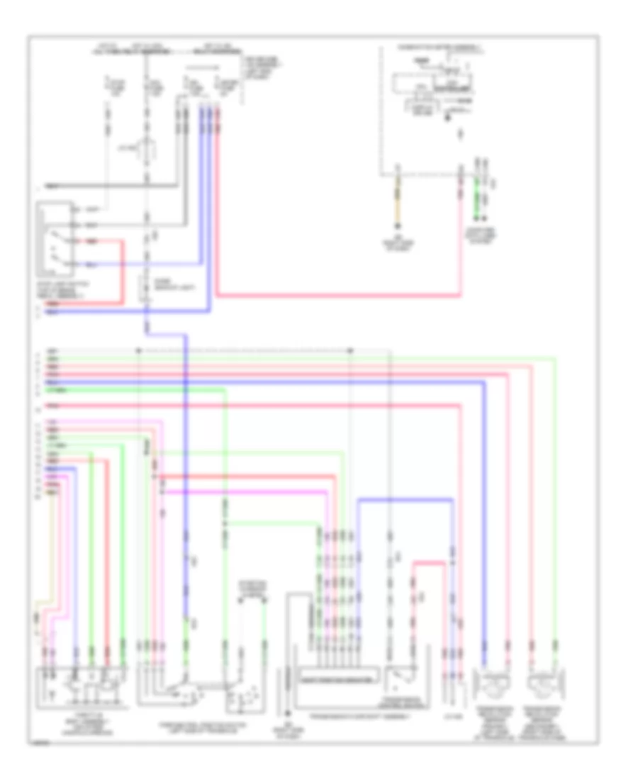
Backup Lamps Wiring Diagram for Toyota Corolla LE Eco 2014
List of elements for Backup Lamps Wiring Diagram for Toyota Corolla LE Eco 2014:
- A/t
- A/t & cvt
- A40
- A42
- A45
- A56
- Ab (behind left headlight)
- Acc
- Acc fuse 7.5a
- Ae2
- Ae4
- B33
- Ba1
- Ba2
- Backup
- Backup light switch assembly (transaxle assembly)
- Bkup lp relay (a/t & cvt)
- Canh
- Canl
- Computer data lines system
- Cvt
- Diode (backup light) (a/t & cvt) (center console)
- Driver side junction block assembly (left end of dash)
- Ecm (left side of engine compt)
- Ecu-ig 2 fuse
- Engine room relay block (left side of engine compt)
- Hot in on or acc
- Hot in on or start
- Ig/acc
- Ig1
- J/c 1
- Lb (left "c" pillar)
- Left rear light assembly
- M/t
- Park/neutral position switch (left side of transaxle)
- Red
- Right rear light assembly
- Shift position indicator
- Transmission floor shift assembly (cvt)
- W/ dual vvt-i
- W/ valvematic
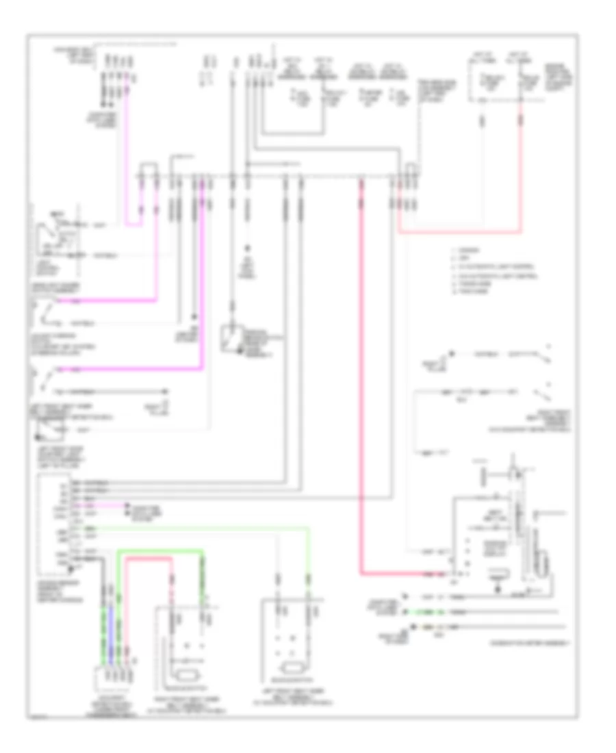
Exterior Lamps Wiring Diagram (1 of 2) for Toyota Corolla LE Eco 2014
List of elements for Exterior Lamps Wiring Diagram (1 of 2) for Toyota Corolla LE Eco 2014:
- (canada w/ tft display) tail ind
- (top of brake pedal assembly) stop light switch
- 5v ic
- 5v+b
- A18
- A19
- A35
- A40
- A44
- Ae3
- Brake actuator assembly (right front of engine compt)
- Buzzer
- C55
- Can controller
- Can h
- Can i/f
- Can l
- Center stop light assembly
- Combination meter assembly
- Computer data lines system
- Cpu
- Cruise control system
- D13
- D31
- D33
- D34
- D39
- D40
- Driver's side junction block assembly (left end of dash)
- E11
- E26
- E27
- E43
- E47
- Ea (left kick panel)
- Ecm (left side of engine compt)
- Ecu-b 2 fuse 7.5a
- Ecu-b fuse 10a
- Ed (right side of dash)
- Engine room relay block (left side of engine compt)
- Ge1
- Haz
- He1
- Hot at all times
- Hot w/ ig2 relay energized
- I/f
- Ig+
- L21
- L22
- Lb (left "c" pillar)
- Led driver
- Left license plate light assembly
- Left outer rear view mirror assembly (w/ outer rear view mirror side turn signal light)
- Left rear combination light assembly
- Left turn ind
- Meter fuse 5a
- Noise filter (radio setting condenser) (left "d" pillar)
- Pnk
- Red
- Right license plate light assembly
- Right outer rear view mirror assembly (w/ outer rear view mirror side turn signal light)
- Right rear combination turn light assembly
- Right turn ind
- Stop
- Stop fuse 10a
- Stp
- Tail/side marker
- Turn
- Turn & haz fuse 10a
- Gl1
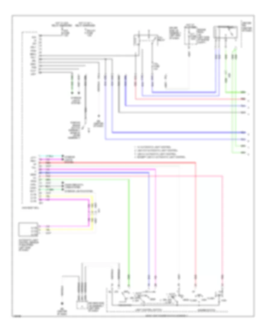
Exterior Lamps Wiring Diagram (2 of 2) for Toyota Corolla LE Eco 2014
List of elements for Exterior Lamps Wiring Diagram (2 of 2) for Toyota Corolla LE Eco 2014:
- (left end of dash) driver's side junction block assembly
- A14
- A20
- A21
- A24
- Aa (behind left headlight)
- Ac (behind right headlight)
- Acc
- Acc fuse 7.5a
- Alt fuse 120a
- Auto drl
- Becu
- C15
- C36
- Canh
- Canl
- Certification ecu (w/ smart key system) (right side of dash)
- Computer data lines system
- D12
- D16
- D17
- Driver's side junction block assembly (left end of dash)
- Drl off off
- E29
- E31
- E34
- E57
- Ea (left kick panel)
- Eb (center of dash)
- Ecu ig 1 fuse 7.5a
- Ed (right side of dash)
- Engine room junction block (left side of engine compt)
- Except usa w/ automatic light control
- Flcy
- Frcy
- Gnd1
- Hazard warning signal
- Head
- Headlight dimmer switch assembly
- Hot at all times
- Hot w/ acc relay energized
- Hot w/ ig1 1 relay energized
- Interior lights system
- Lcty
- Left
- Left headlight assembly
- Light control switch
- Main body ecu
- Panel fuse 5a
- Parking
- Pnk
- Rcty
- Red
- Right
- Right headlight assembly
- Shift lock control ecu (transmission floor shift assembly) (under center console)
- Side marker
- Stp
- Stp1
- Switch assembly
- Tail
- Tail fuse 10a
- Tail relay
- Trly
- Turn
- Turn switch
- Usa w/ automatic light control
- Usa w/o automatic light control
- W/ automatic light control
- W/ smart key system
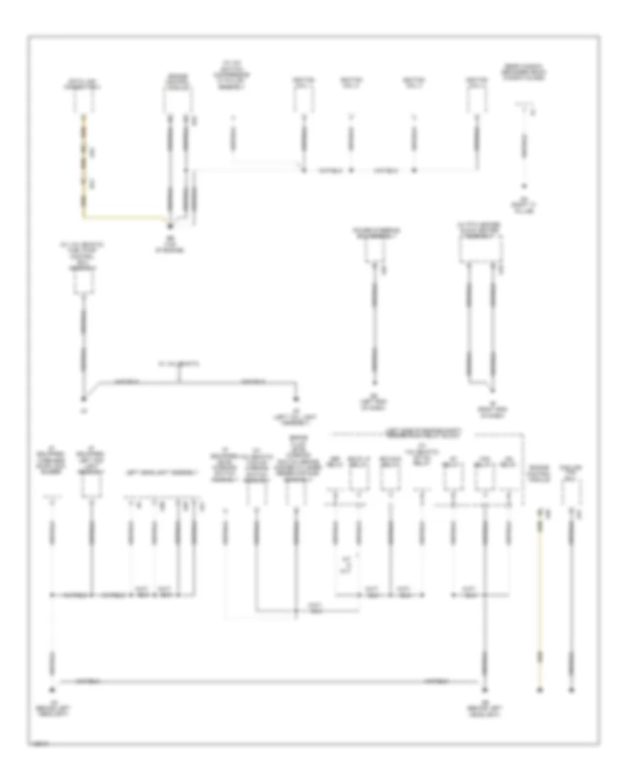
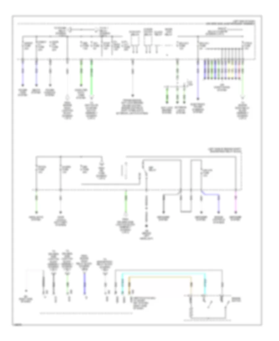
GROUND DISTRIBUTION
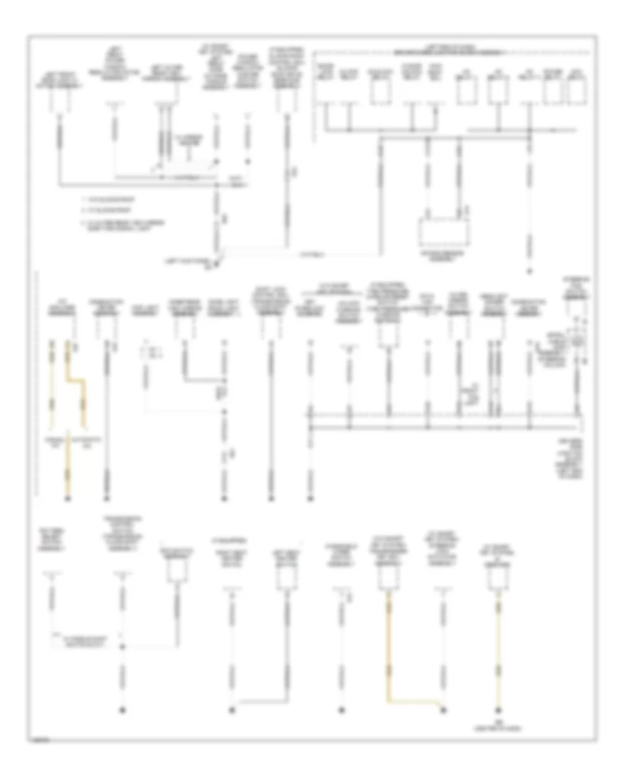
Ground Distribution Wiring Diagram (1 of 5) for Toyota Corolla LE Eco 2014
List of elements for Ground Distribution Wiring Diagram (1 of 5) for Toyota Corolla LE Eco 2014:
- (if equipped) left fog light assembly
- (if equipped) level warning switch assembly
- (if equipped) wireless door lock buzzer
- (left side of engine compt) engine room relay block
- (w/ a/c switch) compressor w/ pulley assembly
- (w/ ptc heater) quick heater assembly
- (w/ valvematic) fuel pump control ecu assembly
- (w/ valvematic) igt/inj relay
- (w/ valvematic) vacuum warning switch assembly
- A/t & cvt
- A10
- A21
- A25
- A28
- A30
- A31
- A40
- Aa (behind left headlight)
- Ab (behind left headlight)
- Ae (left end of dash)
- Ae4
- Af (right end of dash)
- B33
- Ba1
- Bb (top of engine)
- Bkup lp relay
- Brake fluid level warning switch (brake master cylinder reservoir sub- assembly)
- Cooling fan
- Data link connector 3
- Def relay
- Ecu
- Efi-main relay
- Engine control module
- Fan relay 1
- Ig2 relay
- Ignition coil 1
- Ignition coil 2
- Ignition coil 3
- Ignition coil 4
- Le (left tail light assembly)
- Left headlight assembly
- Power steering ecu assembly
- Qa (right "c" pillar)
- Rear window defogger (back window glass)
- St relay 1
- W/ valvematic
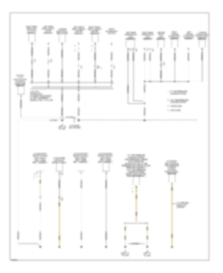
Ground Distribution Wiring Diagram (2 of 5) for Toyota Corolla LE Eco 2014
List of elements for Ground Distribution Wiring Diagram (2 of 5) for Toyota Corolla LE Eco 2014:
- (if equipped) occupant detection ecu
- (w/ dual vvt-i) fuel suction w/ pump & gage tube assembly
- (w/ occupant detection ecu)
- (w/ tire pressure warning system) tire pressure warning ecu & receiver (electrical key & tire pressure monitoring system receiver assembly) (w/o tire pressure warning system) smart door control receiver assembly
- (w/o occupant detection ecu) left front seat inner belt assembly
- (w/o occupant detection ecu) right front seat inner belt assembly
- (w/o smart key system & tire pressure warning system) door control receiver
- Center stop light assembly
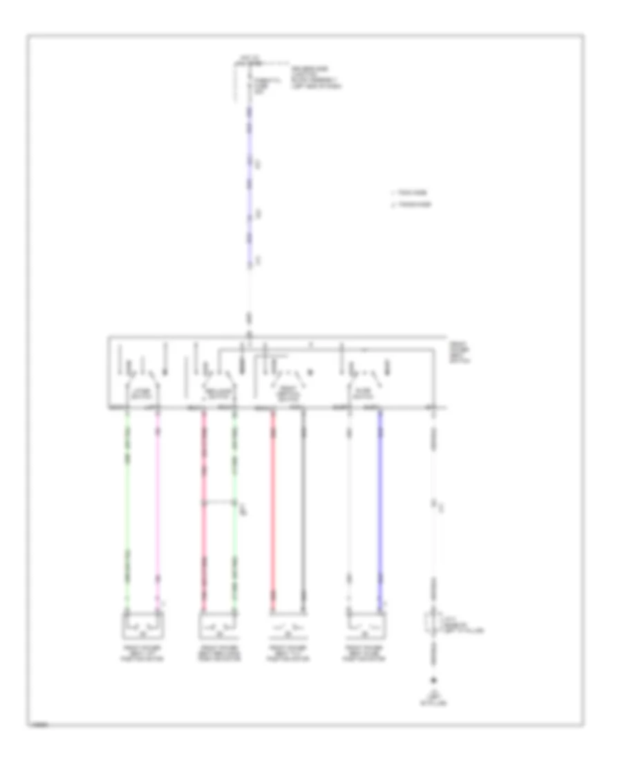
- Front power seat switch
- Jl1
- Junction connector 4 (w/ smart key system & theft deterrent) (base of left "c" pillar)
- Kl1
- L21
- L22
- La (left "b" pillar)
- Lb (left "c" pillar)
- Lc (right "c" pillar)
- Left front seat cushion heater assembly
- Left license plate light assembly
- Left rear combination light assembly
- Left rear door lock w/ motor assembly
- Ls1
- Ls2
- Lt1
- Luggage compartment door lock assembly
- Luggage electrical key switch
- Right front seat cushion heater assembly
- Right front seat inner belt assembly
- Right license plate light assembly
- Right rear combination light assembly
- Right rear door lock w/ motor assembly
- Tmmc made
- Tmmms made
- W/ tire pressure warning system
- W/ wireless door lock control
- W/o smart key system
- W/o tire pressure warning system
- Gl1
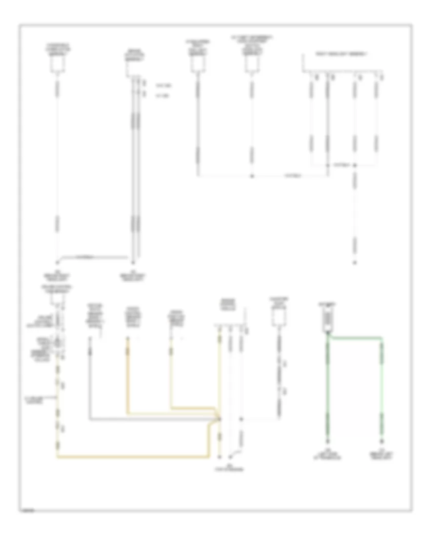
Ground Distribution Wiring Diagram (3 of 5) for Toyota Corolla LE Eco 2014
List of elements for Ground Distribution Wiring Diagram (3 of 5) for Toyota Corolla LE Eco 2014:
- (if equipped) right fog light assembly
- (w/ theft deterrent) hood courtesy switch (hood lock assembly)
- A14
- A20
- A27
- A29
- A41
- A42
- Ac (behind right headlight)
- Ad (behind right headlight)
- Ae3
- Air fuel ratio sensor (bank 1 sensor 1) shield
- Al1
- B33
- Ba (top of engine)
- Ba1
- Battery
- Brake actuator assembly
- Ca (behind left headlight)
- Canister pump module
- Cb (left side of transaxle)
- Crank position sensor shield
- Cruise control main switch
- Cruise control switch wire
- Engine control module
- Knock control sensor (bank 1) shield
- Nca
- Right headlight assembly
- Spiral cable sub- assembly (steering column)
- W/ cruise control
- W/ vsc
- W/o vsc
- Windshield
- Wiper motor assembly
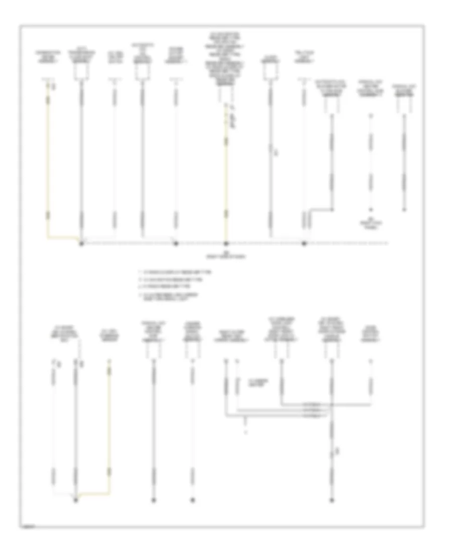
Ground Distribution Wiring Diagram (4 of 5) for Toyota Corolla LE Eco 2014
List of elements for Ground Distribution Wiring Diagram (4 of 5) for Toyota Corolla LE Eco 2014:
- (automatic a/c)
- (automatic a/c) a/c control assembly
- (cvt) transmission floor shift assembly
- (manual a/c)
- (manual a/c) blower resistor
- (w/ navigation receiver type) navigation receiver assembly (w/ radio receiver type) radio receiver assembly (w/ radio & display receiver type) radio & display receiver assembly
- (w/ smart key system)
- (w/ smart key system) certification ecu
- (w/ vsc)
- (w/ vsc) vsc off switch
- (w/ wireless door lock control) right front door lock w/ motor assembly
- Blower motor w/ fan sub- assembly
- Clock assembly
- Combination meter assembly
- Door control switch assembly
- E43
- E57
- E58
- E62
- E65
- Ec (right kick panel)
- Ed (right side of dash)
- Ef1
- Ge1
- Hazard warning signal switch assembly
- Heater control sub- assembly 1
- Heater control sub- assembly 2
- Power outlet socket assembly 1
- Right front door outside handle assembly
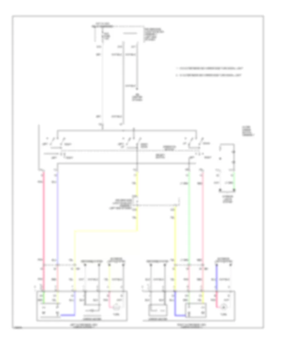
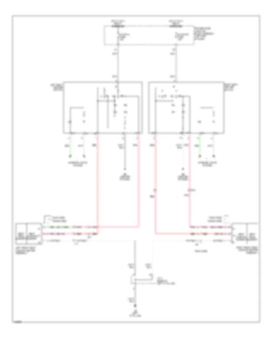
- Right outer rear view mirror assembly
- Steering sensor
- Telltale light assembly
- W/ mirror heater
- W/ navigation receiver type
- W/ outer rear view mirror side turn signal light
- W/ radio & display receiver type
- W/ radio receiver type
Ground Distribution Wiring Diagram (5 of 5) for Toyota Corolla LE Eco 2014
List of elements for Ground Distribution Wiring Diagram (5 of 5) for Toyota Corolla LE Eco 2014:
- (if equipped)
- (if equipped) tire pressure warning reset switch (tire pressure warning switch 1)
- (left end of dash) driver's side junction block assembly
- (left kick panel) ea
- (transmission floor shift assembly)
- (w/ smart key system) id code box
- (w/ smart key system) left front door outside handle assembly
- (w/ smart key system) steering lock actuator assembly
- (w/o smart key system)
- A/c amplifier assembly
- Acc relay
- Air bag sensor assembly
- Automatic a/c
- Bk/dr lock relay
- C26
- C47
- Combination meter assembly
- D door unlock relay
- D/lock relay
- D/unlock relay
- D12
- D16
- D17
- D18
- D19
- D20
- Data link connector
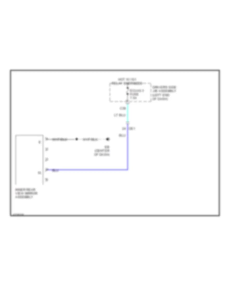
- Dome light (room light assembly 1)
- Driver's side junction block assembly (left end of dash)
- E12
- E14
- E37
- E43
- Eb (center of dash)
- Eco switch assembly
- He2
- Headlight dimmer switch assembly
- Ig1 relay 1
- Ig1 relay 2
- Ig1 relay 3
- Inner rear view mirror assembly
- Key interlock solenoid
- Left front door lock w/ motor assembly
- Left front power window regulator motor assembly
- Left outer rear view mirror assembly
- Left seat heater switch
- Main body ecu
- Manual a/c
- Map light assembly
- O3 o5
- Oe1
- Outer mirror switch assembly
- Pattern select switch assembly
- Power relay
- Power window regulator master switch assembly
- Right seat heater switch
- Shift lock control ecu
- Side turn signal light
- Sliding roof control ecu (sliding roof drive gear sub- assembly)
- Spiral cable sub- assembly (steering column)
- Steering pad switch assembly
- Transmission control switch (transmission floor shift assembly)
- Transponder key ecu assembly
- Un-lock warning switch assembly
- W/ front fog light
- W/ mirror heater
- W/ outer rear view mirror
- W/ paddle shift switch & cvt
- W/ sliding roof
- W/o sliding roof
- Windshield wiper switch assembly
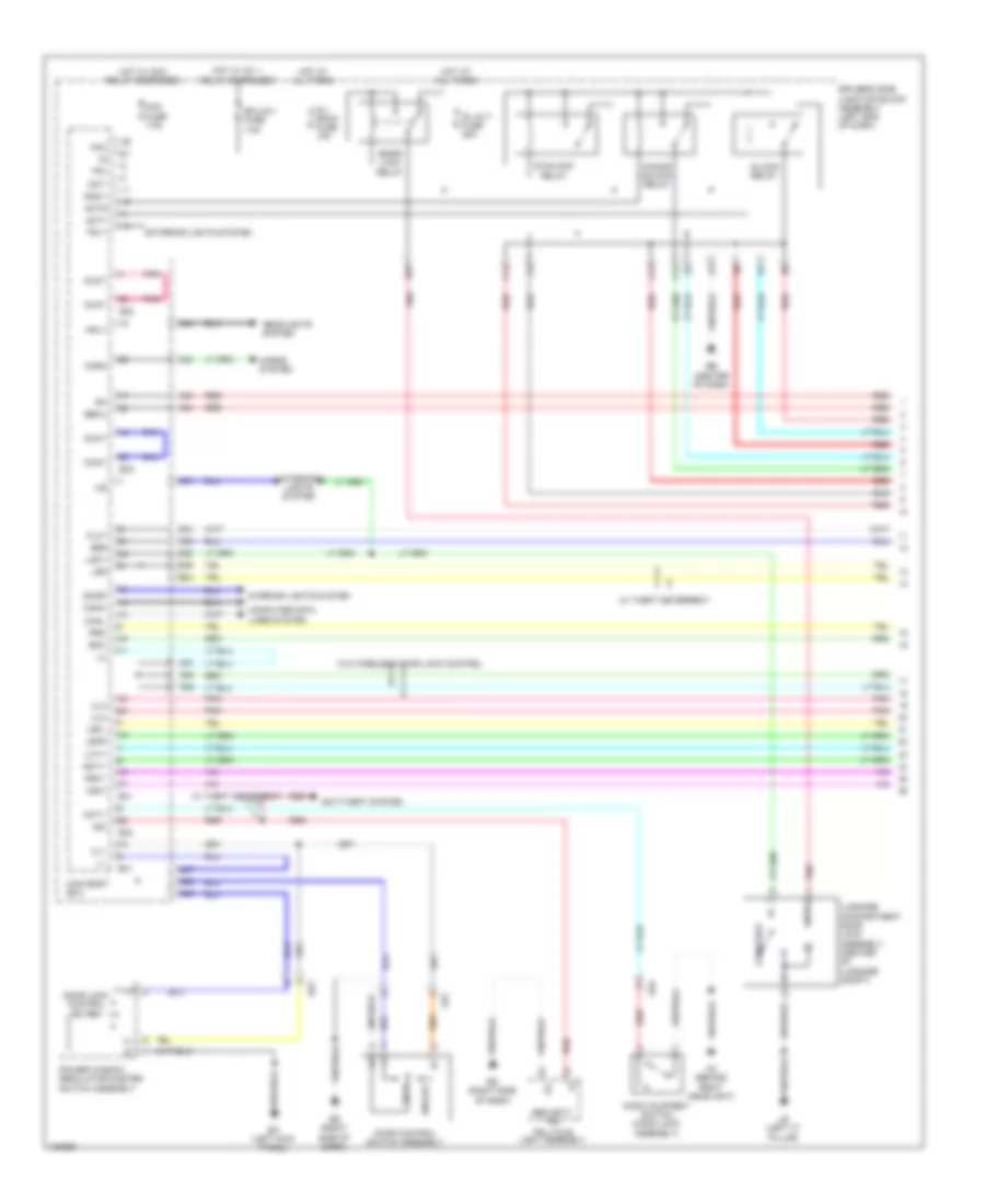
HEADLIGHTS
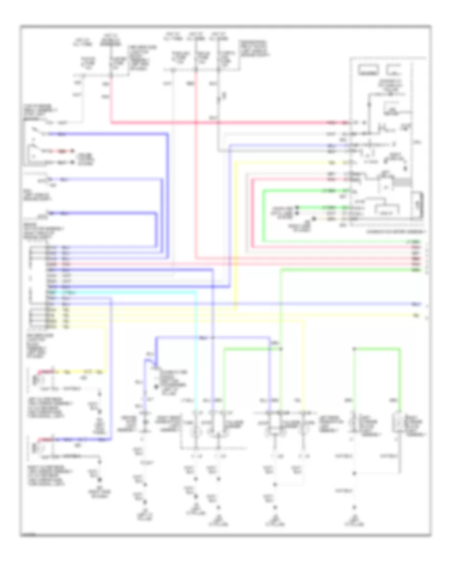
Headlights Wiring Diagram (1 of 2) for Toyota Corolla LE Eco 2014
List of elements for Headlights Wiring Diagram (1 of 2) for Toyota Corolla LE Eco 2014:
- A24
- A28
- A34
- A49
- A50
- Acc
- Acc fuse 7.5a
- Ae6
- Alt fuse 120a
- Auto drl
- Automatic light control sensor (if equipped) (left side of dash)
- Becu
- Bfg
- C43
- Canh
- Canl
- Center r/b (center of dash)
- Cltb
- Clte
- Clts
- Computer data lines system
- D16
- D17
- D37
- Dim
- Dimmer switch
- Driver side j/b assembly (left end of dash)
- Driver's side j/b assembly (left end of dash)
- Drl
- Drl off off
- E30
- E31
- E34
- E38
- Eb (center of dash)
- Ecu-ig 1 fuse 7.5a
- Ef1
- Engine room j/b (left side of engine compt)
- Except usa w/ automatic light control
- Ffgo
- Ffog
- Flash
- Flcy
- Fog switch
- Fr fog relay
- Frcy
- Gnd1
- Head
- Headlight dimmer switch assembly
- High
- Hot at all times
- Hot w/ acc relay energized
- Hot w/ ig1 1 relay energized
- Hrly
- Interior lights system
- Lcty
- Lfg
- Lgcy
- Light control switch
- Low
- Main body ecu
- Parking brake switch assembly (base of lever assembly)
- Pkb
- Pnk
- Rcty
- Red
- Tail
- Tail fuse 10a
- Tail relay
- Trly
- Usa w/ automatic light control
- Usa w/o automatic light control
- W/ automatic light control
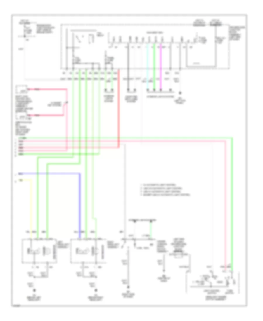
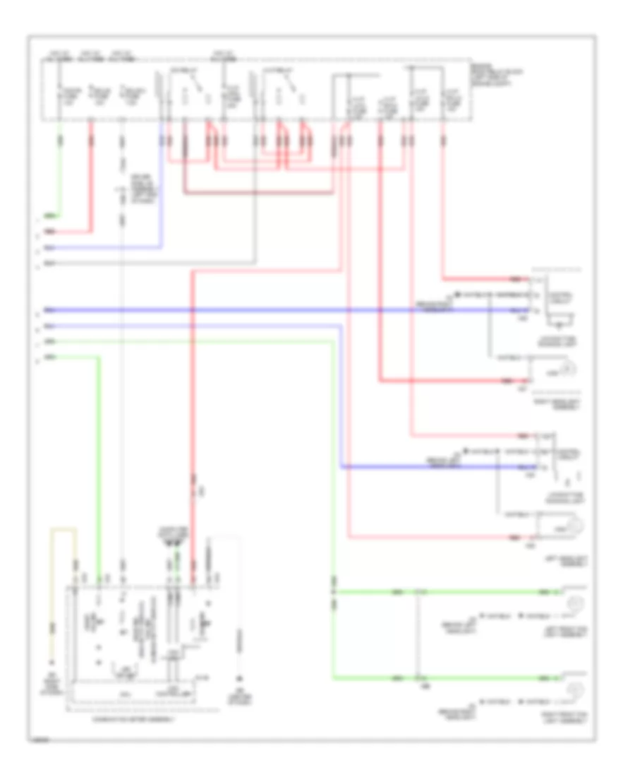
Headlights Wiring Diagram (2 of 2) for Toyota Corolla LE Eco 2014
List of elements for Headlights Wiring Diagram (2 of 2) for Toyota Corolla LE Eco 2014:
- (canada w/ tft display) tail ind
- (usa w/ tft display) head ind
- 5v+b
- A27
- A28
- A29
- A30
- A44
- Aa (behind left headlight)
- Ac (behind right headlight)
- Ae3
- Ae6
- Beam ind
- Can controller
- Can i/f
- Canh
- Canl
- Combination meter assembly
- Computer data lines system
- Control circuit
- Cpu
- D40
- Dim relay
- Driver side j/b assembly (left end of dash)
- E43
- E47
- Eb (center of dash)
- Ecu-b 2 fuse 7.5a
- Ecu-b fuse 10a
- Ed (right side of dash)
- Engine room relay block (left side of engine compt)
- Fog fr fuse 10a
- Fog ind front
- H-lp lh-hi fuse 10a
- H-lp lh-lo fuse 10a
- H-lp main fuse 40a
- H-lp relay
- H-lp rh-hi fuse 10a
- H-lp rh-lo fuse 10a
- High
- Hot at all times
- Led driver
- Left front fog light assembly
- Left headlight assembly
- Low/daytime running light
- Red
- Right front fog light assembly
- Right headlight assembly
HORN
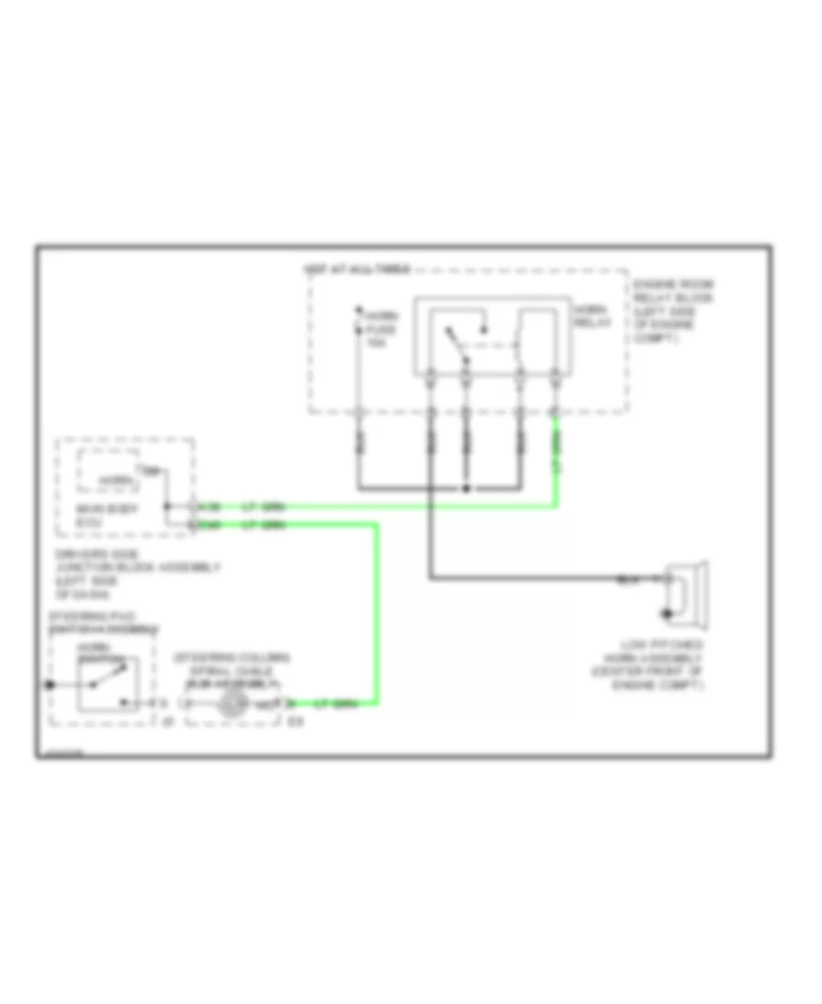
Horn Wiring Diagram for Toyota Corolla LE Eco 2014
List of elements for Horn Wiring Diagram for Toyota Corolla LE Eco 2014:
- (steering column) spiral cable sub-assembly
- A38
- C49
- Driver's side junction block assembly (left side of dash)
- Engine room relay block (left side of engine compt)
- Horn
- Horn fuse 10a
- Horn relay
- Horn switch
- Hot at all times
- Low pitched horn assembly (center front of engine compt)
- Main body ecu
- Steering pad switch assembly
INSTRUMENT CLUSTER
Instrument Cluster Wiring Diagram (1 of 3) for Toyota Corolla LE Eco 2014
List of elements for Instrument Cluster Wiring Diagram (1 of 3) for Toyota Corolla LE Eco 2014:
- (front of engine) engine oil pressure switch assembly
- (if equipped) cruise ind
- (if equipped) tire pressure ind
- (if equipped) vsc off ind
- (if equipped) washer ind
- (usa) trac off ind (canada) trc off ind
- (w/ vsc) slip ind
- (w/o tft display)
- (w/o tft display) charge ind
- (w/o tft display) eco ind
- (w/o tft display) fuel ind
- 5v ic
- 5v+b
- A10
- A11
- A12
- A13
- A14
- A15
- A16
- A17
- A19
- A21
- A28
- A29
- A31
- A32
- A33
- A34
- A35
- A36
- A37
- A39
- A40
- Abs ind
- Ae3
- Anti-lock brakes system
- B10
- B12
- B13
- Ba1
- Beam ind
- Brake ind
- Buzzer
- Can controller
- Can i/f
- Canh
- Canl
- Chg-
- Chk
- Combination meter assembly
- Computer data lines system
- Cpu
- D17
- D18
- Display driver
- Display) switch & tft (w/ paddle shift sport ind
- Door ind (w/o tft display)
- Driver's side junction block assembly (left end of dash)
- E43
- Eb (center of dash)
- Eco ind (w/ tft display)
- Eco mode ind (w/o tft display w/ eco switch)
- Ed (right side of dash)
- Electrical key ind (w/ smart key system w/o tft display)
- Engine controls system
- Front fog ind
- Fuel ind (w/ tft display)
- Head ind (usa w/ tft display) tail ind (canada w/ tft display)
- Headlight dimmer switch assembly
- Headlights system
- Hi water temperature ind
- I/f
- Ig+
- Ill-
- Illumination ind
- Ind lamp malfunction
- Indicator)
- Interior lights system
- Led driver
- Left turn ind
- Master ind (w/ tft display)
- Oil pressure ind (w/o tft display)
- P/sb
- Pnk
- Power steering ind
- Red
- Right turn ind
- Seat belt ind
- Set ind (w/ cruise control)
- Srs ind
- Starting/charging system
- Sw1
- Sw2
- Sw3
- Tx1+
- Tx1-
- W/ oil maintenance (w/o tft display & maint reqd ind
- W/ tft display
- W/ tft display & level warning switch
- W/o tft display
- Warning systems
- Wiper/washer system
- Wlvl
Instrument Cluster Wiring Diagram (2 of 3) for Toyota Corolla LE Eco 2014
List of elements for Instrument Cluster Wiring Diagram (2 of 3) for Toyota Corolla LE Eco 2014:
- (fuel tank assembly) fuel suction w/ pump & gauge tube assembly
- A44
- Ab (behind left headlight)
- Ae3
- Ambient temperature sensor (thermistor assembly) (front of engine compt)
- Brake fluid level warning switch (brake master cylinder reservoir sub assembly) (brake fluid reservoir)
- C55
- Combination meter assembly
- D17
- D40
- Disp
- Driver's side junction block assembly (left end of dash)
- E47
- Eb (center of dash)
- Ecu-b 2 fuse 7.5a
- Ecu-b fuse 10a
- El1
- Engine room relay block (left side of engine compt)
- Exterior lights system
- Fog
- Gauge
- Haz
- Headlights system
- Hot at all times
- Hot w/ ig2 relay energized
- J/c 1
- Left steering switch
- Meter fuse 5a
- Pnk
- Red
- Right steering switch
- Spiral cable sub assembly (steering column)
- Steering pad switch assembly
- Turn & haz fuse 10a
- Vacuum warning switch assembly (w/ valvematic) (left rear of engine compt)
- W/ dual vvt-i
- W/ valvematic
Instrument Cluster Wiring Diagram (3 of 3) for Toyota Corolla LE Eco 2014
List of elements for Instrument Cluster Wiring Diagram (3 of 3) for Toyota Corolla LE Eco 2014:
- A24
- A40
- A48
- Acc
- Acc fuse 7.5a
- Becu
- C23
- C41
- Canh
- Canl
- Certification ecu (w/ smart key system) (right side of dash)
- Clock assembly
- Computer data lines system
- D11
- D12
- D28
- D29
- D32
- Driver's side junction block assembly (left end of dash)
- E29
- E30
- E31
- E34
- E59
- E64
- E67
- Ea (left kick panel)
- Ecm (left side of engine compt)
- Ecu-ig 1 fuse 7.5a
- Ed (right side of dash)
- Ef1
- El1
- El2
- Flcy
- Frcy
- Gnd1
- Hot w/ acc relay energized
- Hot w/ ig1 1 relay energized
- Ill+
- Ill-
- Interior lights system
- Lcty
- Left front door courtesy light switch assembly (left "b" pillar)
- Left rear door courtesy light switch assembly (base of left "c" pillar)
- Main body ecu
- Parking brake switch assembly (base of lever assembly)
- Pkb
- Radio receiver assembly (w/ radio receiver type) navigation receiver assembly (w/ navigation receiver type) radio & display receiver assembly (w/ radio & display receiver type)
- Rcty
- Red
- Right front door courtesy light switch assembly (right "b" pillar)
- Right rear door courtesy light switch assembly (base of right "c" pillar)
- Spd
- W/ navigation receiver type
- W/ radio & display receiver type
- W/ radio receiver type
INTERIOR LIGHTS
Courtesy Lamps Wiring Diagram (1 of 2) for Toyota Corolla LE Eco 2014
List of elements for Courtesy Lamps Wiring Diagram (1 of 2) for Toyota Corolla LE Eco 2014:
- (left kick panel) ea
- (right side of dash) ed
- A24
- A51
- Acc
- Acc fuse 7.5a
- Bctl
- Becu
- C42
- C54
- Canh
- Canl
- Computer data lines system
- D26
- Dome cut relay
- Domr
- Driver's side junction block assembly (left end of dash)
- E24
- E31
- E34
- E38
- E39
- E40
- Eb (center of dash)
- Ecu-ig1 1 fuse 7.5a
- El1
- El2
- Flcy
- Frcy
- Ge1
- Gnd 1
- He2
- Hot w/ acc relay energized
- Hot w/ ig1 1 relay energized
- Ile
- Jl1
- Kl1
- Lb (left "c" pillar)
- Lcty
- Left front door courtesy light switch assembly (left "b" pillar)
- Left front door lock w/ motor assembly
- Left rear door courtesy light switch assembly (base of left "c" pillar)
- Lgcy
- Lgyl bcyl
- Lsfl
- Lsfr
- Lsr
- Luggage compartment courtesy door lock assembly (center of luggage compt)
- Luggage compartment light assembly 1
- Main body ecu
- Oe1
- Pnk
- Rcty
- Red
- Right front door courtesy light switch assembly (right "b" pillar)
- Right front door lock w/ motor assembly
- Right rear door courtesy light switch assembly (base of right "c" pillar)
- Unlock detection
- W/ theft deterrent
- W/o theft deterrent
Courtesy Lamps Wiring Diagram (2 of 2) for Toyota Corolla LE Eco 2014
List of elements for Courtesy Lamps Wiring Diagram (2 of 2) for Toyota Corolla LE Eco 2014:
- +b1
- Cty
- Dome fuse 10a
- Dome light (room light assembly 1)
- Door
- Eb (center of dash)
- Ecu-b fuse 10a
- Engine room relay block (left side of engine compt)
- Hot at all times
- Jl1
- Junction connector l49 (right side of dash)
- Kl1
- Lb (left 'c" pillar)
- Left rear door lock w/ motor assembly
- Map light assembly
- Off
- Red
- Right rear door lock w/ motor assembly
- Unlock detection
- W/ sliding roof
- W/o sliding roof
Instrument Illumination Wiring Diagram (1 of 3) for Toyota Corolla LE Eco 2014
List of elements for Instrument Illumination Wiring Diagram (1 of 3) for Toyota Corolla LE Eco 2014:
- (right side of dash) ed
- A24
- Acc
- Acc fuse 7.5a
- Alt fuse 120a
- Auto drl
- Becu
- C15
- C36
- C55
- Canh
- Canl
- Computer data lines system
- D12
- D16
- D17
- Dim
- Driver's side junction block assembly (left end of dash)
- Drl off off
- E31
- Ea (left kick panel)
- Eb (center of dash)
- Engine room junction block (left side of engine compt)
- Except usa w/ automatic light control
- Gnd1
- Head
- Headlight dimmer switch assembly
- Heater control sub-assembly 3 (manual a/c)
- Hot at all times
- Hot w/ acc relay energized
- Hot w/ ig1 relay energized
- Ill-
- Left steering switch
- Light control switch
- Main body ecu (left end of dash)
- Meter fuse 5a
- Msw+
- Msw-
- Panel fuse 5a
- Pattern select switch assembly (if equipped)
- Pnk
- Red
- Right steering switch
- Shift position ind
- Spiral cable sub-assembly (steering column)
- Steering pad
- Switch assembly
- Tail
- Tail relay
- Telltale light assembly
- Transmission floor shift assembly (a/t & cvt)
- Trly
- Usa w/ automatic light control
- Usa w/o automatic light control
- W/ automatic light control
Instrument Illumination Wiring Diagram (2 of 3) for Toyota Corolla LE Eco 2014
List of elements for Instrument Illumination Wiring Diagram (2 of 3) for Toyota Corolla LE Eco 2014:
- (left end of dash)
- A44
- Clock assembly
- D40
- Driver's side junction block assembly
- Ecu-b 2 fuse 7.5a
- Ecu-b fuse 10a
- Ef1
- Engine room relay block (left side of engine compt)
- Heater control sub-assembly 1 (manual a/c) (center of dash)
- Hot at all times
- Ill+
- Ill-
- Junction connector e53 (right side of dash)
- Junction connector e54 (right side of dash)
- Pnk
- Red
- Vsc off switch (if equipped)
Instrument Illumination Wiring Diagram (3 of 3) for Toyota Corolla LE Eco 2014
List of elements for Instrument Illumination Wiring Diagram (3 of 3) for Toyota Corolla LE Eco 2014:
- (automatic a/c) a/c control assembly
- (right side of dash) (w/ smart key system) certification ecu assembly
- (w/ radio & display receiver type) radio & display receiver assembly (w/ navigation receiver type) navigation receiver assembly (w/ radio receiver type) radio receiver assembly
- 5v ic
- 5v+b
- Agnd
- Can controller
- Can i/f
- Canh
- Canl
- Combination meter assembly
- Computer data lines system
- Cpu
- E43
- E59
- E62
- E63
- E65
- E66
- Eco switch assembly (if equipped)
- Ed (right side of dash)
- Engine switch
- Hazard warning signal switch assembly
- Heater control sub-assembly 2 (manual a/c) (center of dash)
- I/f
- Ill+
- Ill-
- Illumination
- Led driver
- Left seat heater switch (if equipped)
- Light control rheostat
- Outer mirror switch assembly
- Pnk
- Red
- Right seat heater switch (if equipped)
- Sw1
- Sw2
- Sw3
- Swil
- Tail cancel switch
- W/ navigation receiver type
- W/ radio & display receiver type
- W/ radio receiver type
NAVIGATION
Navigation Wiring Diagram (1 of 3) for Toyota Corolla LE Eco 2014
List of elements for Navigation Wiring Diagram (1 of 3) for Toyota Corolla LE Eco 2014:
- +b1
- 5v +b
- 5v ic
- 5v+b
- A44
- Acc fuse 7.5a
- Acc1
- Ae3
- Agnd
- Alo
- Aro
- Asgn
- Au1
- Au2
- Auxo
- Back
- C37
- C41
- C55
- Can controller
- Can i/f
- Canh
- Canl
- Combination meter assembly
- Computer data lines system
- Cpu
- D14
- D40
- Down
- Driver's side junction block assembly (left end of dash)
- E30
- E43
- E65
- E66
- E8 au3 spiral cable sub-assembly (steering column)
- Eau
- Ecu-b 2 fuse 7.5a
- Ecu-ig 3 fuse 7.5a
- Ed (right side of dash)
- El1
- El2
- Engine room relay block (left side of engine compt)
- Enter
- Eu1
- Fl+
- Fl-
- Fr+
- Fr-
- Gnd1
- Hot at all times
- Hot w/ acc relay energized
- Hot w/ ig1 relay energized
- Hot w/ ig2 relay energized
- Ig+
- Ill+
- Ill-
- Interior lights system
- Left
- Left rear speaker assembly
- Left steering switch
- Meter fuse 5a
- Mode
- Nca
- Off hook
- On hook
- Parking brake switch (base of lever assembly)
- Pnk
- Radio & display receiver assembly (w/o navigation) navigation receiver assembly (w/ navigation)
- Radio fuse 20a
- Red
- Right
- Right rear speaker assembly
- Right steering switch
- Rl+
- Rl-
- Rr+
- Rr-
- Steering pad switch assembly
- Stereo jack adapter assembly 1
- Udo+
- Udo-
- Ujsg
- Up1
- Voice
- Vol+
- Vol-
- W/ navigation
- W/o navigation
Navigation Wiring Diagram (2 of 3) for Toyota Corolla LE Eco 2014
List of elements for Navigation Wiring Diagram (2 of 3) for Toyota Corolla LE Eco 2014:
- A/t
- A/t & cvt
- A40
- A42
- A45
- A56
- Ab (behind left headlight)
- Acc
- Acc fuse 7.5a
- Ae2
- Ae4
- B33
- Ba1
- Ba2
- Backup
- Backup light switch assembly (transaxle assembly)
- Bkup lp relay (a/t & cvt)
- Canh
- Canl
- Computer data lines system
- Cvt
- D38
- Diode (backup light) (a/t & cvt) (center console)
- Driver side junction block assembly (left end of dash)
- Ecm (left side of engine compt)
- Ecu-ig 2 fuse
- Engine room relay block (left side of engine compt)
- Hot in on or acc
- Hot in on or start
- Ig/acc
- Ig1
- J/c 1
- Lb (left "c" pillar)
- Left rear light assembly
- M/t
- Nca
- Park/neutral position switch (left side of transaxle)
- Pnk
- Red
- Right rear light assembly
- Shift position indicator
- Transmission floor shift assembly (cvt)
- W/ dual vvt-i
- W/ valvematic, a/t & cvt
Navigation Wiring Diagram (3 of 3) for Toyota Corolla LE Eco 2014
List of elements for Navigation Wiring Diagram (3 of 3) for Toyota Corolla LE Eco 2014:
- (overhead console assembly) (w/ microphone) microphone amplifier assembly
- (w/ microphone) map light assembly
- +b2
- 4 speaker
- 6 speaker
- Acc2
- Adpg
- Agnd
- Ca+
- Can h
- Can l
- Cb+
- Cgnd
- Computer data lines system
- Cv+
- Cv-
- E29
- E30
- E67
- E68
- El1
- Ge1
- Ggnd
- Gnd2
- Gps antenna (w/ navigation)
- He1
- Instrument cluster system
- Left front speaker assembly 1
- Left front speaker assembly 2
- Lv1
- Macc
- Macc red
- Mic+
- Mic-
- Microphone
- Min+
- Min-
- Nca
- Oe1
- Pkb
- Pnk
- Radio & display receiver assembly (w/o navigation) navigation receiver assembly (w/ navigation)
- Radio antenna
- Rear television camera assembly (w/ rear view monitor system)
- Red
- Rev
- Right front speaker assembly 1
- Right front speaker assembly 2
- Sdars antenna
- Sgnd
- Sns2
- Spd
- Speaker
- Stereo component tuner assembly (if equipped)
- Sw1
- Sw2
- Sw3
- Swg
- Twl+
- Twl-
- Twr+
- Twr-
- Ugd1
- Ugd4
- Us1+
- Us1-
- Us4
- Us4+
- Us4-
- Usg4
- Usv1
- Usv4
- Va-
- Val+
- Var+
- W/ navigation
- W/ rear view monitor system
- W/ sliding roof
- W/o navigation
- W/o sliding roof
POWER DISTRIBUTION
Power Distribution Wiring Diagram (1 of 3) for Toyota Corolla LE Eco 2014
List of elements for Power Distribution Wiring Diagram (1 of 3) for Toyota Corolla LE Eco 2014:
- (left end of dash) driver's side junction block assembly
- (left side of engine compt) engine room relay block
- A/b fuse 10a
- A10
- A23
- A24
- A36
- A37
- A44
- Ab (behind left headlight)
- Abs 1 fuse 50a
- Abs 2 fuse 30a
- Ae3
- Air conditioning & cooling fans systems
- Air conditioning system
- Alt fuse 120a
- Am2 fuse 7.5a
- Anti-lock brakes & electronic power steering systems
- Anti-lock brakes system
- Anti-theft system
- Battery
- Becu
- C/opn relay
- C23
- C44
- C55
- Cruise control, exterior lights & engine controls systems
- D/c cut fuse 30a
- D22
- D40
- D41
- Dome fuse 10a
- Door locks & anti-theft systems
- Door locks, anti-theft & warning systems
- E from certification ecu (diagram 3 of 3)
- E20
- E31
- E33
- E35
- Ecu-b 2 fuse 7.5a
- Ecu-b fuse 10a
- Efi main fuse 20a
- Efi main relay
- Electronic power steering system
- Engine controls system
- Engine room junction block (left side of engine compt)
- Eps fuse 80a
- Etcs fuse 10a
- Exterior lights system
- From acc relay (diagram 2 of 3)
- From ig1 1 relay k (diagram 2 of 3)
- From ignition or starter switch assembly (diagram 2 of 3)
- From strg lock fuse (diagram 1 of 3)
- H-lp main fuse 40a
- H-lp relay
- Horn fuse 10a
- Horn relay
- Htr fuse 50a
- Htr sub 1 fuse 30a
- Htr sub 3 fuse 30a
- Ics fuse 5a
- Ig1 2 relay
- Ig2 fuse 15a
- Ig2 relay
- Ign fuse 7.5a
- Igt/inj relay
- Inj fuse 15a
- Instrument cluster system
- Interior lights system
- Main body ecu
- Meter fuse 5a
- Navigation & sound systems
- Pnk
- Radio fuse 20a
- Rdi fuse 30a
- Red
- Shift interlock & door locks systems
- Shift interlock system
- St 1 relay
- St fuse 30a
- Starting/ charging system
- Strg lock fuse 20a
- To certification ecu (diagram 3 of 3)
- To d/c cut fuse (diagram 1 of 3)
- To def fuse (diagram 3 of 3)
- To driver's side junction block assembly (diagram 3 of 3)
- To ig1 1 relay (diagram 2 of 3)
- To ignition or starter switch assembly (diagram 2 of 3)
- Transmissions & engine controls systems
- Turn & haz fuse 10a
- Vlvmatic fuse 30a
- W/ dual vvt-i
- W/ ptc heater
- W/ smart key system
- W/o smart key system
- Warning systems
- Washer fuse 15a
- Wiper fuse 25a
- Wiper/washer system
Power Distribution Wiring Diagram (2 of 3) for Toyota Corolla LE Eco 2014
List of elements for Power Distribution Wiring Diagram (2 of 3) for Toyota Corolla LE Eco 2014:
- (left end of dash) driver's side junction block assembly
- (not used)
- (right side of dash) ed
- A15
- A16
- A20
- A21
- A39
- A41
- A45
- Acc
- Acc fuse 7.5a
- Acc relay
- Am1
- Am2
- Anti-lock brakes & electronic power steering systems
- C15
- C16
- C17
- C18
- C19
- C36
- C37
- C38
- C39
- C40
- C50
- D14
- D15
- D25
- D27
- D32
- D37
- E28
- E29
- Eb (center of dash)
- Ecu-ig 1 fuse 7.5a
- Ecu-ig 3 fuse 7.5a
- Engine controls & starting/charging systems
- Engine controls system
- Exterior lights system
- From certification ecu (diagram 3 of 3)
- From driver's side junction block assembly (diagram 3 of 3)
- From engine room relay block (diagram 1 of 3)
- From ig1 2 relay (diagram 1 of 3)
- From ignition or starter switch assembly (diagram 2 of 3)
- From obd fuse (diagram 3 of 3)
- Headlights system
- Ig1
- Ig1 1 relay
- Ig1 3 relay
- Ig2
- Ignition or starter switch assembly (w/o smart key system)
- Instrument cluster system
- Interior lights system
- J/c a38
- Lock
- Main body ecu
- Mirrors system
- Navigation & sound systems
- Off
- On off
- P from certification ecu (diagram 3 of 3)
- P/ outlet fuse 15a
- Panel fuse 5a
- Power outlet socket assembly 1
- Power relay
- Power tops system
- S/htr f/l fuse 15a
- S/htr f/r fuse 15a
- Seats system
- Sft lock fuse 5a
- Shift interlock system
- St1
- St2
- Start
- Starting/ charging system
- Tail fuse 10a
- Tail relay
- To driver's side junction block assembly (diagram 2 of 3)
- To engine room relay block (diagram 1 of 3)
- To htr-ig fuse (diagram 3 of 3)
- To ig1 2 relay (diagram 1 of 3)
- Transmissions system
- Trly
- W/ dual vvt-i
- W/ smart key system
- W/ valvematic
- W/o smart key system
- Warning systems
Power Distribution Wiring Diagram (3 of 3) for Toyota Corolla LE Eco 2014
List of elements for Power Distribution Wiring Diagram (3 of 3) for Toyota Corolla LE Eco 2014:
- (left end of dash) driver's side junction block assembly
- (left side of engine compt) engine room relay block
- A25
- A26
- A35
- A46
- A47
- A56
- Ab (behind left headlight)
- Accd
- Agnd
- Air conditioning system
- Am1 fuse 5a
- Anti-lock brakes system
- Bk/dr lock relay
- Certification ecu (w/ smart key system) (right side of dash)
- Computer data lines system
- D door unlock relay
- D/l alt fuse 25a
- D/l back fuse 10a
- D/lock relay
- D/unlock relay
- D10
- D21
- D23
- D24
- D30
- D42
- D43
- D44
- D45
- D46
- D48
- Def fuse 50a
- Def relay
- Defogger system
- Door f/r fuse 20a
- Door locks & anti-theft systems
- E10
- E57
- E59
- Ecu-ig 2 fuse 10a
- Ecu-ig 4 fuse 5a
- Ed (right side of dash)
- Electronic power steering system
- Engine controls systems
- Engine switch
- Exterior lights system
- Fr fog fuse 10a
- From driver's side junction block assembly (diagram 3 of 3)
- From ecu-ig 3 fuse (diagram 2 of 3)
- From engine room junction block (diagram 1 of 3)
- From engine room relay block (diagram 1 of 3)
- From rdi fuse (diagram 1 of 3)
- Headlights system
- Htr-ig fuse 10a
- Ig1d
- Ig2d
- J/c a38
- Mir htr fuse 10a
- Obd fuse 7.5a
- P/seat f/l fuse 30a
- Pnk
- Power tops system
- Power windows system
- S-horn fuse 10a
- S/roof fuse 20a
- Seats system
- Ss1
- Ss2
- Ssw1
- Ssw2
- Stop fuse 10a
- To driver's side junction block assembly (diagram 2 of 3)
- To engine room relay block (diagram 1 of 3)
- To engine room relay block assembly (diagram 3 of 3)
- To ig1 1 relay (diagram 2 of 3)
- To ignition or starter switch assembly (diagram 2 of 3)
- To power relay (diagram 2 of 3)
- Transmissions, anti-lock brakes, cruise control, engine controls, shift interlock & exterior lights systems
POWER DOOR LOCKS
Power Door Locks Wiring Diagram, with Smart Key System (1 of 5) for Toyota Corolla LE Eco 2014
List of elements for Power Door Locks Wiring Diagram, with Smart Key System (1 of 5) for Toyota Corolla LE Eco 2014:
- A24
- A34
- A38
- A53
- A54
- Ac (behind right headlight)
- Acc
- Acc fuse 7.5a
- Act+
- Act-
- Actd
- Ae4
- Becu
- Bk/dr lock relay
- Bzr
- C12
- C13
- C14
- C20
- C21
- C27
- C28
- C29
- C54
- Canh
- Canl
- Computer data lines system
- Courtesy
- D door unlock relay
- D/l back fuse 10a
- D/l-alt fuse 25a
- D/lock relay
- D/unlock relay
- D12
- Door control switch assembly
- Driver's side junction block assembly (left end of dash)
- Dumy
- E24
- E31
- E32
- E34
- E37
- E38
- E39
- Ea (left kick panel)
- Ecu-ig 1 fuse 7.5a
- Ed (right side of dash)
- El2
- Exterior lights system
- Flcy
- Frcy
- Ge1
- Gnd1
- Hcty
- He1
- He2
- Headlights system
- Hood courtesy switch (hood lock assembly)
- Horn
- Horns system
- Hot at all times
- Hot w/ acc relay energized
- Hot w/ ig1 1 relay energized
- Hrly
- Ile
- Ind
- Interior lights system
- Lb (left "c" pillar)
- Lcty
- Lgcy
- Lsfl
- Lsfr
- Lsr
- Luggage compartment door lock assembly (center of luggage compt)
- Main body ecu
- Pnk
- Power window regulator master switch assembly
- Rcty
- Red
- Right front door courtesy light switch assembly (right "b" pillar)
- Right rear door courtesy light switch assembly (base of right "c" pillar)
- Tr+
- Trly
- Ul1
- Ul3
- W/ theft deterrent
Power Door Locks Wiring Diagram, with Smart Key System (2 of 5) for Toyota Corolla LE Eco 2014
List of elements for Power Door Locks Wiring Diagram, with Smart Key System (2 of 5) for Toyota Corolla LE Eco 2014:
- (right front of engine compt) brake actuator assembly
- 5v ic
- 5v+b
- A44
- Aa (behind left headlight)
- Ae3
- Buzzer
- C55
- Can controller
- Can i/f
- Canh
- Canl
- Combination meter assembly
- Computer data lines system
- Cpu
- D11
- D28
- D40
- Door ind
- Driver display
- Driver's side junction block assembly (left end of dash)
- E43
- Ea (left kick panel)
- Ed (right side of dash)
- El1
- Electrical key ind
- Ge1
- He1
- He2
- Hot w/ ig2 relay energized
- I/f
- Ig+
- Led driver
- Left front door courtesy light switch assembly (left "b" pillar)
- Left front door lock w/ motor assembly
- Left rear door courtesy light switch assembly (base of left "c" pillar)
- Lock key
- Lssr
- Master ind
- Meter fuse 5a
- Pnk
- Red
- Right front door lock w/ motor assembly
- Sp1
- Tion detec- unlock
- Unlock key
- W/ tft display
- W/ theft deterrent
- W/ vsc
- W/o tft display
- W/o vsc
- Wireless door lock buzzer (left side of dash)
Power Door Locks Wiring Diagram, with Smart Key System (3 of 5) for Toyota Corolla LE Eco 2014
List of elements for Power Door Locks Wiring Diagram, with Smart Key System (3 of 5) for Toyota Corolla LE Eco 2014:
- Ante6
- Ante7
- Clgb
- Ecu-b 2 fuse 7.5a
- Ecu-b fuse 10a
- El1
- El2
- Engine room relay block (left side of engine compt)
- Hot at all times
- Indoor electrical key antenna assembly 2 (right side chassis, near b pillar)
- Indoor electrical key antenna assembly 3 (left rear of luggage compt)
- J/c 4 (base of left "c" pillar)
- Jl1
- Kl1
- La (left "b" pillar)
- Lb (left "c" pillar)
- Left rear door lock w/ motor assembly
- Lssr
- Red
- Right rear door lock w/ motor assembly
- S-horn fuse 10a
- S-horn relay (w/ theft deterrent)
- Security horn assembly
- Tion detec- unlock
Power Door Locks Wiring Diagram, with Smart Key System (4 of 5) for Toyota Corolla LE Eco 2014
List of elements for Power Door Locks Wiring Diagram, with Smart Key System (4 of 5) for Toyota Corolla LE Eco 2014:
- (left side of engine compt) ecm
- (right "c" pillar) tire pressure warning ecu & receiver (electrical key & tire pressure monitoring system receiver assembly)
- A40
- Ant1
- Ant2
- Ante8
- Canh
- Canl
- Certification ecu (right side of dash)
- Cg6b
- Cg7b
- Cg8b
- Clg6
- Clg7
- Clg8
- Clgb
- Computer data lines system
- Csel
- Data
- E58
- Ed (right side of dash)
- El1
- El2
- Ge2
- Gnd
- Idw
- J/c 4 (base of left c pillar)
- La (left "b" pillar)
- Lb (left "c" pillar)
- Lc (right "c" pillar)
- Luggage electrical key switch (top center of trunk lid)
- Neo
- Pnk
- Rco
- Rdam
- Rear electrical key antenna (rear bumper assembly)
- Red
- Right front door outside handle assembly
- Sens
- Smart door control receiver assembly
- Trg+
- Tsw5
- W/ tire pressure warning system
- W/o tire pressure warning system
Power Door Locks Wiring Diagram, with Smart Key System (5 of 5) for Toyota Corolla LE Eco 2014
List of elements for Power Door Locks Wiring Diagram, with Smart Key System (5 of 5) for Toyota Corolla LE Eco 2014:
- (right side chassis, near "b" pillar) indoor electrical key antenna assembly 1
- A19
- A24
- A35
- Accd
- Ae2
- Ae3
- Agnd
- Am2 fuse 7.5a
- Ant1
- Ant2
- Ante5
- Antenna coil
- Canh
- Canl
- Certification ecu (right side of dash)
- Cg1b
- Cg2b
- Cg5b
- Clg1
- Clg2
- Clg5
- Clgb
- Code
- Computer data lines system
- Cutb
- D39
- Driver's side junction block assembly (left end of dash)
- Dumy
- E57
- E59
- Ea (left kick panel)
- Ecu-b fuse 10a
- Ed (right side of dash)
- El2
- Engine room relay block (left side of engine compt)
- Engine switch
- Gnd
- He2
- Hot at all times
- Hot w/ ig2 relay energized
- Ig1d
- Ig2d
- Ign fuse 7.5a
- Ill-
- Ind
- Left front door outside handle assembly
- Lin
- Pnk
- Pos1
- Pos2
- Power distribution system
- Red
- Security ind
- Sen1
- Sen2
- Sens
- Shift interlock system
- Slp
- Slr+
- Spd
- Ss1
- Ss2
- Ssw1
- Ssw2
- Sta
- Star
- Starting/charging system
- Stop fuse 10a
- Stop light switch assembly (top of brake pedal assembly)
- Stp1
- Swil
- Telltale light assembly
- Trg+
- Tsw1
- Tsw2
- Txct
- Vc5
Power Door Locks Wiring Diagram, without Smart Key System (1 of 3) for Toyota Corolla LE Eco 2014
List of elements for Power Door Locks Wiring Diagram, without Smart Key System (1 of 3) for Toyota Corolla LE Eco 2014:
- A24
- A34
- A38
- A53
- A54
- Ac (behind right headlight)
- Acc
- Acc fuse 7.5a
- Act+
- Act-
- Actd
- Ae4
- Anti-theft system
- Becu
- Bk/dr lock relay
- Bzr
- C12
- C13
- C14
- C20
- C21
- C22
- C27
- C28
- C29
- C54
- Canh
- Canl
- Computer data lines system
- Courtesy
- D door unlock relay
- D/l back fuse 10a
- D/l-alt fuse 25a
- D/lock relay
- D/unlock relay
- Domr
- Door control switch assembly
- Door lock control switch
- Driver's side junction block assembly (left end of dash)
- Dumy
- E24
- E31
- E32
- E34
- E37
- E38
- E39
- Ea (left kick panel)
- Eb (center of dash)
- Ecu-ig 1 fuse 7.5a
- Ed (right side of dash)
- Exterior lights system
- Flcy
- Frcy
- Ge1
- Gnd1
- Hcty
- He1
- Headlights system
- Hood courtesy switch (hood lock assembly)
- Horn
- Horns system
- Hot at all times
- Hot w/ acc relay energized
- Hot w/ ig1 1 relay energized
- Hrly
- Ile
- Ill-
- Ind
- Interior lights system
- Ksw
- Lb (left "c" pillar)
- Lcty
- Lgcy
- Lock
- Lsfl
- Lsfr
- Lsr
- Luggage compartment door lock assembly (center of luggage compt)
- Main body ecu
- Pnk
- Power window regulator master switch assembly
- Prg
- Rcty
- Rda
- Red
- Security ind
- Telltale light assembly
- Tr+
- Trly
- Ul1
- Ul2
- Ul3
- Unlock
- W/ theft deterrent
- W/o wireless door lock control
Power Door Locks Wiring Diagram, without Smart Key System (2 of 3) for Toyota Corolla LE Eco 2014
List of elements for Power Door Locks Wiring Diagram, without Smart Key System (2 of 3) for Toyota Corolla LE Eco 2014:
- 5v ic
- 5v+b
- A44
- Buzzer
- C30
- C32
- C55
- Can controller
- Can i/f
- Canh
- Canl
- Combination meter assembly
- Computer data lines system
- Cpu
- D17
- D40
- Detection unlock
- Door ind (w/o tft display)
- Driver display
- Driver's side junction block assembly (left end of dash)
- E43
- Ea (left kick panel)
- Eb (center of dash)
- Ecu-b 2 fuse 7.5a
- Ed (right side of dash)
- El1
- El2
- Engine room relay block (left side of engine compt)
- Ge1
- He1
- He2
- Hot at all times
- Hot w/ ig2 relay energized
- I/f
- Ig+
- Key lock
- Key un- lock
- Led driver
- Left front door lock w/ motor assembly
- Left rear door courtesy light switch assembly (base of left "c" pillar)
- Lock
- Lock key
- Lssr
- Meter fuse 5a
- Pnk
- Red
- Right front door courtesy light switch assembly (right "b" pillar)
- Right front door lock w/ motor assembly
- Right rear door courtesy light switch assembly (base of right "c" pillar)
- Un- key
- Un-lock warning switch (steering column)
- W/ theft deterrent
- W/ wireless door lock control
- W/o wireless door lock control
Power Door Locks Wiring Diagram, without Smart Key System (3 of 3) for Toyota Corolla LE Eco 2014
List of elements for Power Door Locks Wiring Diagram, without Smart Key System (3 of 3) for Toyota Corolla LE Eco 2014:
- (left "c" pillar) door control receiver
- (left end of dash) driver's side junction block assembly
- (right "c" pillar) tire pressure warning ecu & receiver (door control & tire pressure monitoring system receiver assembly)
- A24
- Aa (behind left headlight)
- Detection unlock
- E31
- Ecu-b fuse 10a
- El1
- Engine room relay block (left side of engine compt)
- Gnd
- Hot at all times
- J/c 4 (base of left "c" pillar)
- Jl1
- Kl1
- Lb (left "c" pillar)
- Lc (right "c" pillar)
- Left front door courtesy light switch assembly (left "b" pillar)
- Left rear door lock w/ motor assembly
- Lssr
- Prg
- Rda
- Red
- Right rear door lock w/ motor assembly
- S-horn fuse 10a
- S-horn relay (w/ theft deterrent)
- Security horn assembly
- W/ theft deterrent
- W/ tire pressure warning system
- W/o tire pressure warning system
- Wireless door lock buzzer (left side of dash)
POWER MIRRORS
Electrochromic Mirror Wiring Diagram for Toyota Corolla LE Eco 2014
List of elements for Electrochromic Mirror Wiring Diagram for Toyota Corolla LE Eco 2014:
- C38
- Driver's side j/b assembly (left end of dash)
- Eb (center of dash)
- Ecu-ig 3 fuse 7.5a
- Hot w/ ig1 relay energized
- Inner rear view mirror assembly
- Oe1
Power Mirrors Wiring Diagram for Toyota Corolla LE Eco 2014
List of elements for Power Mirrors Wiring Diagram for Toyota Corolla LE Eco 2014:
- Acc fuse 7.5a
- C33
- C34
- C35
- D15
- D17
- D19
- Defogger system
- Down
- Driver's side junction block assembly (left end of dash)
- Eb (center of dash)
- Exterior lights system
- Ge1
- He1
- Hot w/ acc relay energized
- Ill+
- Ill-
- Interior lights system
- Left
- Left outer rear view mirror assembly
- Left/
- Mirror heater
- Operation switch
- Outer mirror switch assembly
- Pnk
- Red
- Right
- Right outer rear view mirror assembly
- Right/ down
- Select switch
- Turn
- W/ outer rearview mirror side turn signal light
- W/o outer rearview mirror side turn signal light
POWER SEATS
Heated Seats Wiring Diagram for Toyota Corolla LE Eco 2014
List of elements for Heated Seats Wiring Diagram for Toyota Corolla LE Eco 2014:
- Driver's side junction block assembly (left end of dash)
- Eb (center of dash)
- El1
- El2
- Hot w/ ig1 3 relay energized
- Ill+
- Ill-
- Interior lights system
- J/c 4 (base of left "c" pillar)
- Lb (left "c" pillar)
- Left front seat cushion heater assembly
- Left seat heater switch
- Ls1
- Lt1
- Pnk
- Red
- Right front seat cushion heater assembly
- Right seat heater switch
- S-htr f/l fuse 15a
- S-htr f/r fuse 15a
- Seat back element
- Seat cushion element
- Tmmc made
- Tmmms made
Power Seats Wiring Diagram for Toyota Corolla LE Eco 2014
List of elements for Power Seats Wiring Diagram for Toyota Corolla LE Eco 2014:
- (or pnk)
- Al1
- Al2
- Down
- Driver's side junction block assembly (left end of dash)
- E10
- Fdwn
- Front
- Front power seat lift position motor
- Front power seat reclining position motor
- Front power seat slide position motor
- Front power seat switch
- Front power seat tilt position motor
- Front vertical switch
- Fup
- Hot at all times
- J/c 4 (base of left "c" pillar)
- La (left "b" pillar)
- Ldwn
- Lifter switch
- Lt1
- Lup
- P/seat f/l fuse 30a
- Pnk
- Rclf
- Rclr
- Rear
- Reclining switch
- Red
- Sldf
- Sldr
- Slide switch
- Tmmc made
- Tmmms made
- Wt1
POWER TOP/SUNROOF
Power Top/Sunroof Wiring Diagram for Toyota Corolla LE Eco 2014
List of elements for Power Top/Sunroof Wiring Diagram for Toyota Corolla LE Eco 2014:
- (w/ tft display)
- (w/ tft display) driver display
- 5v ic
- 5v+b
- A24
- A44
- Acc
- Acc fuse 7.5a
- Becu
- Buzzer
- C19
- C53
- C55
- Can i/f
- Canh
- Canl
- Cls
- Combination meter assembly
- Computer data lines system
- Controller can
- Cpu
- D12
- D40
- Down
- Driver's side junction block assembly (left end of dash)
- Dwn
- E31
- E34
- E43
- Ea (left kick panel)
- Eb (center of dash)
- Ecu-b 2 fuse 7.5a
- Ecu-b fuse 10a
- Ecu-ig 1 fuse 7.5a
- Ecu-ig 3 fuse 7.5a
- Ed (right side of dash)
- El2
- Engine room r/b (left side of engine compt)
- Flcy
- Frcy
- Gnd1
- Gnd3
- Hot at all times
- Hot w/ acc relay energized
- Hot w/ ig1 1 relay energized
- Hot w/ ig2 relay energized
- I/f
- Ig+
- Led driver
- Left front door courtesy light switch assembly (left "b" pillar)
- Lin2
- Main body ecu
- Map light assembly
- Master ind
- Meter fuse 5a
- Mpx1
- Oe1
- Opn
- Pnk
- Red
- Right front door courtesy light switch assembly (right "b" pillar)
- S/roof fuse 20a
- Sliding roof control ecu (sliding roof driving gear sub-assembly) (front center of roof)
- Sliding roof control switch
POWER WINDOWS
Power Windows Wiring Diagram (1 of 2) for Toyota Corolla LE Eco 2014
List of elements for Power Windows Wiring Diagram (1 of 2) for Toyota Corolla LE Eco 2014:
- A24
- Acc fuse 7.5a
- Alt fuse 120a
- Becu
- C10
- C11
- C52
- C56
- D12
- Door f/r fuse 20a
- Door locks system
- Door r/l fuse 20a
- Door r/r fuse 20a
- Down
- Driver's side junction block assembly (left end of dash)
- E31
- E34
- Ea (left kick panel)
- Eb (center of dash)
- El1
- Engine room junction block (left side of engine compt)
- Flcy
- Frcy
- Ge1
- Gnd1
- He1
- He2
- Hot at all times
- Hot w/ acc relay energized
- Kl1
- Koff
- Led
- Left rear power window regulator motor assembly
- Left rear power window regulator switch assembly
- Lin2
- Main body ecu
- Pnk
- Power fuse 30a
- Power relay
- Power window regulator master switch assembly
- Red
- Right front power window regulator motor assembly
- Right front power window regulator switch down assembly
Power Windows Wiring Diagram (2 of 2) for Toyota Corolla LE Eco 2014
List of elements for Power Windows Wiring Diagram (2 of 2) for Toyota Corolla LE Eco 2014:
- Cpu
- Down
- Ea (left kick panel)
- Ecu-b fuse 10a
- El2
- Engine room relay block (left side of engine compt)
- He1
- He2
- Hot at all times
- Jl1
- Left front door courtesy light switch assembly (left "b" pillar)
- Left front power window regulator motor assembly
- Pnk
- Red
- Right front door courtesy light switch assembly (right "b" pillar)
- Right rear power window regulator motor assembly
- Right rear power window regulator switch assembly
RADIO
Radio Wiring Diagram, with Radio & Display Receiver Type (1 of 3) for Toyota Corolla LE Eco 2014
List of elements for Radio Wiring Diagram, with Radio & Display Receiver Type (1 of 3) for Toyota Corolla LE Eco 2014:
- +b1
- 5v +b
- 5v ic
- 5v+b
- A44
- Acc fuse 7.5a
- Acc1
- Ae3
- Agnd
- Alo
- Aro
- Asgn
- Au1
- Au2
- Auxo
- Back
- C37
- C41
- C55
- Can controller
- Can i/f
- Canh
- Canl
- Combination meter assembly
- Computer data lines system
- Cpu
- D14
- D40
- Down
- Driver's side junction block assembly (left end of dash)
- E30
- E43
- E65
- E66
- E8 au3 spiral cable sub-assembly (steering column)
- Eau
- Ecu-b 2 fuse 7.5a
- Ecu-ig 3 fuse 7.5a
- Ed (right side of dash)
- El1
- El2
- Engine room relay block (left side of engine compt)
- Enter
- Eu1
- Fl+
- Fl-
- Fr+
- Fr-
- Gnd1
- Hot at all times
- Hot w/ acc relay energized
- Hot w/ ig1 relay energized
- Hot w/ ig2 relay energized
- Ig+
- Ill+
- Ill-
- Interior lights system
- Left
- Left rear speaker assembly
- Left steering switch
- Meter fuse 5a
- Mode
- Nca
- Off hook
- On hook
- Parking brake switch (base of lever assembly)
- Pnk
- Radio & display receiver assembly (w/o navigation) navigation receiver assembly (w/ navigation)
- Radio fuse 20a
- Red
- Right
- Right rear speaker assembly
- Right steering switch
- Rl+
- Rl-
- Rr+
- Rr-
- Steering pad switch assembly
- Stereo jack adapter assembly 1
- Udo+
- Udo-
- Ujsg
- Up1
- Voice
- Vol+
- Vol-
- W/ navigation
- W/o navigation
Radio Wiring Diagram, with Radio & Display Receiver Type (2 of 3) for Toyota Corolla LE Eco 2014
List of elements for Radio Wiring Diagram, with Radio & Display Receiver Type (2 of 3) for Toyota Corolla LE Eco 2014:
- A/t
- A/t & cvt
- A40
- A42
- A45
- A56
- Ab (behind left headlight)
- Acc
- Acc fuse 7.5a
- Ae2
- Ae4
- B33
- Ba1
- Ba2
- Backup
- Backup light switch assembly (transaxle assembly)
- Bkup lp relay (a/t & cvt)
- Canh
- Canl
- Computer data lines system
- Cvt
- D38
- Diode (backup light) (a/t & cvt) (center console)
- Driver side junction block assembly (left end of dash)
- Ecm (left side of engine compt)
- Ecu-ig 2 fuse
- Engine room relay block (left side of engine compt)
- Hot in on or acc
- Hot in on or start
- Ig/acc
- Ig1
- J/c 1
- Lb (left "c" pillar)
- Left rear light assembly
- M/t
- Nca
- Park/neutral position switch (left side of transaxle)
- Pnk
- Red
- Right rear light assembly
- Shift position indicator
- Transmission floor shift assembly (cvt)
- W/ dual vvt-i
- W/ valvematic, a/t & cvt
Radio Wiring Diagram, with Radio & Display Receiver Type (3 of 3) for Toyota Corolla LE Eco 2014
List of elements for Radio Wiring Diagram, with Radio & Display Receiver Type (3 of 3) for Toyota Corolla LE Eco 2014:
- (overhead console assembly) (w/ microphone) microphone amplifier assembly
- (w/ microphone) map light assembly
- +b2
- 4 speaker
- 6 speaker
- Acc2
- Adpg
- Agnd
- Ca+
- Can h
- Can l
- Cb+
- Cgnd
- Computer data lines system
- Cv+
- Cv-
- E29
- E30
- E67
- E68
- El1
- Ge1
- Ggnd
- Gnd2
- Gps antenna (w/ navigation)
- He1
- Instrument cluster system
- Left front speaker assembly 1
- Left front speaker assembly 2
- Lv1
- Macc
- Macc red
- Mic+
- Mic-
- Microphone
- Min+
- Min-
- Nca
- Oe1
- Pkb
- Pnk
- Radio & display receiver assembly (w/o navigation) navigation receiver assembly (w/ navigation)
- Radio antenna
- Rear television camera assembly (w/ rear view monitor system)
- Red
- Rev
- Right front speaker assembly 1
- Right front speaker assembly 2
- Sdars antenna
- Sgnd
- Sns2
- Spd
- Speaker
- Stereo component tuner assembly (if equipped)
- Sw1
- Sw2
- Sw3
- Swg
- Twl+
- Twl-
- Twr+
- Twr-
- Ugd1
- Ugd4
- Us1+
- Us1-
- Us4
- Us4+
- Us4-
- Usg4
- Usv1
- Usv4
- Va-
- Val+
- Var+
- W/ navigation
- W/ rear view monitor system
- W/ sliding roof
- W/o navigation
- W/o sliding roof
Radio Wiring Diagram, without Radio & Display Receiver Type (1 of 2) for Toyota Corolla LE Eco 2014
List of elements for Radio Wiring Diagram, without Radio & Display Receiver Type (1 of 2) for Toyota Corolla LE Eco 2014:
- +b1
- 5v +b
- 5v ic
- A44
- Acc fuse 7.5a
- Acc1
- Ae3
- Au2
- C55
- Can controller
- Can i/f
- Canh
- Canl
- Combination meter assembly
- Computer data lines system
- Cpu
- D14
- D40
- Driver's side junction block assembly (left end of dash)
- E43
- E62
- E63
- E8 au1 spiral cable sub assembly (steering column)
- Eau
- Ecu-b 2 fuse 7.5a
- Ed (right side of dash)
- El1
- El2
- Engine room relay block (left side of engine compt)
- Fl+
- Fl-
- Fr+
- Fr-
- Gnd1
- Hot at all times
- Hot w/ acc relay energized
- Hot w/ ig2 relay energized
- Ig+
- Ill+
- Ill-
- Interior lights system
- Left rear speaker assembly
- Left steering switch
- Meter fuse 5a
- Mode
- Off hook
- On hook
- Pnk
- Radio fuse 20a
- Radio receiver assembly
- Red
- Right rear speaker assembly
- Right steering switch
- Rl+
- Rl-
- Rr+
- Rr-
- Seek+
- Seek-
- Steering pad switch assembly
- Voice
- Vol+
- Vol-
Radio Wiring Diagram, without Radio & Display Receiver Type (2 of 2) for Toyota Corolla LE Eco 2014
List of elements for Radio Wiring Diagram, without Radio & Display Receiver Type (2 of 2) for Toyota Corolla LE Eco 2014:
- (overhead console assembly) (w/ microphone) microphone amplifier assembly
- (w/ microphone) map light assembly
- 4 speaker
- 6 speaker
- Adpg
- Agnd
- Alo
- Aro
- Asgn
- Auxo
- E64
- Eu1
- Ge1
- He1
- Instrument cluster system
- Left front speaker assembly 1
- Left front speaker assembly 2
- Macc
- Mic+
- Mic-
- Microphone
- Min+
- Min-
- Nca
- Oe1
- Pnk
- Radio antenna
- Radio receiver assembly
- Red
- Right front speaker assembly 1
- Right front speaker assembly 2
- Sgnd
- Sns2
- Spd
- Stereo jack adapter assembly 1
- Sw1
- Sw2
- Swg
- Twl+
- Twl-
- Twr+
- Twr-
- Udo+
- Udo-
- Ugd1
- Ujsg
- Up1
- Us1+
- Us1-
- Usv1
- Va-
- Val+
- Var+
- W/ sliding roof
- W/o sliding roof
SHIFT INTERLOCK
Shift Interlock Wiring Diagram for Toyota Corolla LE Eco 2014
List of elements for Shift Interlock Wiring Diagram for Toyota Corolla LE Eco 2014:
- (center of dash) eb
- (right side of dash) ed
- A/t
- A19
- A35
- A40
- A45
- A56
- Acc
- Acc fuse 7.5a
- Ae2
- Ae3
- Ae4
- Am2 fuse 7.5a
- B d
- B33
- Ba1
- Ba2
- C16
- C40
- Canh
- Canl
- Certification ecu (right side of dash)
- Computer data lines system
- Cvt
- D17
- D39
- Diode (back-up light) (center console)
- Driver side j/b assembly (left end of dash)
- E57
- E59
- Eb (center of dash)
- Ecm (left side of engine compt)
- Ecu ig 3 fuse 7.5a
- Ecu-ig 2 fuse
- Engine room relay block (left side of engine compt)
- Hot at all times
- Hot in on or acc
- Hot in on or start
- J/c a38
- Key interlock solenoid (w/o smart key system) (steering column assembly)
- Kls+
- P position detection switch
- Park/neutral position switch (left side of transaxle)
- Pnk
- Red
- Sft lock 5a
- Shift lock control ecu (transmission floor shift assembly) (under center console)
- Shift lock solenoid
- Shift position indicator
- Sls+
- Sls-
- Stop fuse 10a
- Stop light switch (top of brake pedal assembly)
- Stp
- Transmission floor shift assembly (cvt)
- W/ dual vvt-i
- W/ smart key system
- W/ valvematic
- W/o smart key system
Steering Column Wiring Diagram for Toyota Corolla LE Eco 2014
List of elements for Steering Column Wiring Diagram for Toyota Corolla LE Eco 2014:
- Ae2
- Canh
- Canl
- Certification ecu (right side of dash)
- Computer data lines system
- Driver side j/b assembly (left end of dash)
- E57
- E59
- Eb (center of dash)
- Ed (right side of dash)
- Engine room relay block (left side of engine compt)
- Gnd
- Hot at all times
- Hot in on or start
- Id code box (center of dash)
- Ig2
- Ige
- Ign fuse 7.5a
- Lin
- Pnk
- Slp
- Slp1
- Slr+
- Steering lock actuator assembly (steering column)
- Strg lock fuse 20a
STARTING/CHARGING
Charging Wiring Diagram, Dual VVT-I for Toyota Corolla LE Eco 2014
List of elements for Charging Wiring Diagram, Dual VVT-I for Toyota Corolla LE Eco 2014:
- +bm
- 5v ic
- 5v+b
- A40
- Ab (behind left headlight)
- Ae3
- Alt
- Alt fuse 120a
- B33
- Ba1
- Ba2
- Battery
- C55
- Ca (behind left headlight)
- Can controller
- Can i/f
- Canh
- Canl
- Cb (left side of transaxle)
- Charge ind (w/o tft display)
- Combination meter assembly
- Computer data lines system
- Cpu
- Display driver
- Driver's side junction block assembly (left end of dash)
- E43
- Ecm (left side of engine compt)
- Ed (right side of dash)
- Engine room j/b (left side of engine compt)
- Engine room r/b (left side of engine compt)
- Etcs fuse 10a
- Generator w/ regulator assembly
- Hot w/ ig2 relay energized
- Ig+
- Led driver
- Meter fuse 5a
- Pnk
- Starter assembly
- W/ tft display
- W/o tft display
Charging Wiring Diagram, Valvematic for Toyota Corolla LE Eco 2014
List of elements for Charging Wiring Diagram, Valvematic for Toyota Corolla LE Eco 2014:
- 5v ic
- 5v+b
- A45
- Acc
- Acc fuse 7.5a
- Alt fuse 120a
- Am21
- Ba1
- Battery
- C55
- Ca (behind left headlight)
- Ca3n
- Ca3p
- Can controller
- Can i/f
- Canh
- Canl
- Cb (left side of transaxle)
- Charge ind (w/o tft display)
- Combination meter assembly
- Computer data lines system
- Cpu
- Driver's side junction block assembly (left end of dash)
- E43
- Ed (right side of dash)
- Engine room j/b (left side of engine compt)
- Engine room r/b (left side of engine compt)
- Generator control ecu assembly (left front of engine compt)
- Generator w/ regulator assembly
- Hot w/ acc relay energized
- Hot w/ ig2 relay energized
- Ics fuse 5a
- Ig+
- J/c a38
- Led drive
- Lin
- Lin 1
- Meter fuse 5a
- Pnk
- Red
- Starter assembly
Starting Wiring Diagram (1 of 2) for Toyota Corolla LE Eco 2014
List of elements for Starting Wiring Diagram (1 of 2) for Toyota Corolla LE Eco 2014:
- A/t & cvt
- A29
- A30
- A31
- A32
- A33
- A52
- Ab (behind left headlight)
- Acc
- Ae3
- Alt fuse 120a
- Am2
- Am2 fuse 7.5a
- Ba3
- Battery
- C51
- Ca (behind left headlight)
- Cb (left side of transaxle)
- Driver's side junction block assembly (left end of dash)
- Ecu-b fuse 10a
- Engine room j/b (left side of engine compt)
- Engine room r/b (left side of engine compt)
- Ignition or starter switch assembly
- Lock
- M/t
- Off
- Red
- St 1 relay
- St fuse 30a
- St2
- Start
- Starter assembly
- W/ smart key system
- W/o smart key system
Starting Wiring Diagram (2 of 2) for Toyota Corolla LE Eco 2014
List of elements for Starting Wiring Diagram (2 of 2) for Toyota Corolla LE Eco 2014:
- A/t
- A/t & cvt
- A24
- A40
- Ab (behind left headlight)
- Ae4
- Agnd
- B33
- Ba1
- Canh
- Canl
- Certification ecu (w/ smart key system) (right side of dash)
- Clutch start switch assembly (m/t) (clutch pedal assembly)
- Computer data lines system
- Cutb
- Cvt
- Driver's side junction block assembly (left end of dash)
- E57
- E59
- Ecm (left side of engine compt)
- Ed (right side of dash)
- Engine switch (w/ smart key system)
- Nsw
- Park/neutral position switch (left side of transaxle)
- Pnk
- Red
- Ss1
- Ss2
- Ssw1
- Ssw2
- Sta
- Star
SUPPLEMENTAL RESTRAINTS
Supplemental Restraints Wiring Diagram (1 of 2) for Toyota Corolla LE Eco 2014
List of elements for Supplemental Restraints Wiring Diagram (1 of 2) for Toyota Corolla LE Eco 2014:
- (w/ occupant detection ecu) instrument panel passenger air bag w/o door assembly
- (w/ occupant detection ecu) lower instrument panel air bag assembly 1
- +sl
- +sr
- -sl
- -sr
- A/b fuse 10a
- Air bag sensor assembly (front of center console)
- Bbl+
- Bbl-
- Bbr+
- Bbr-
- Bcr+
- Bcr-
- Bdr+
- Bdr-
- Buckle switch
- C17
- C55
- Canh
- Canl
- Computer data lines system
- Cushion air bag squib (w/ occupant detection ecu)
- D2+
- D2-
- Dk+
- Dk-
- Driver side squib assembly
- Driver's side j/b assembly (left end of dash)
- E14
- E33
- Ecu-ig 3 fuse 7.5a
- Ed1
- Ed2
- Fcp+
- Fcp-
- Fsr+
- Fsr-
- Gl1
- Hot in on or start
- Icl+
- Icl-
- Icr+
- Icr-
- Ig2
- Instrument panel passenger air bag w/o door assembly
- L11
- L47
- Lbe+
- Lbe-
- Lc (right "c" pillar)
- Left front seat air bag assembly (w/ occupant detection ecu)
- Left front seat inner belt assembly (w/ occupant detection ecu)
- Limit switch
- Ls2
- Lc1
- Le1
- Lf1
- Meter fuse 5a
- P-ab
- P2+
- P2-
- Paon
- Pl+
- Pl-
- Pnk
- Pr+
- Pr-
- Red
- Right curtain shield air bag assembly (w/ occupant detection ecu) (right roof rail)
- Right front seat air bag assembly (w/ occupant detection ecu)
- Right front seat inner belt assembly (tmmms made)
- Right front seat outer belt assembly (right "b" pillar)
- Right rear side air bag sensor (w/ occupant detection ecu) (base of right "c" pillar)
- Right side air bag sensor assembly (w/ occupant detection ecu) (right "b" pillar)
- Right side door air bag sensor (front passenger's door)
- Sfl+
- Sfl-
- Sfr+
- Sfr-
- Spiral cable sub-assembly (steering column)
- W/ occupant detection ecu
- W/o occupant detection ecu
Supplemental Restraints Wiring Diagram (2 of 2) for Toyota Corolla LE Eco 2014
List of elements for Supplemental Restraints Wiring Diagram (2 of 2) for Toyota Corolla LE Eco 2014:
- (left "b" pillar) left front seat outer belt assembly
- (left roof rail) (w/ occupant detection ecu) left curtain shield air bag assembly
- (left side of grille) left front air bag sensor
- (right "c" pillar) lc
- (right side of grille) right front air bag sensor
- +sl
- +sr
- -sl
- -sr
- 5v ic
- 5v+b
- A24
- A44
- Ae5
- Bbl+
- Bbl-
- Bcl+
- Bcl-
- Bdl+
- Bdl-
- Becu
- Bgnd
- Bsw
- Buckle switch
- C26
- C47
- Can controller
- Can i/f
- Canh
- Canl
- Combination meter assembly
- Computer data lines system
- Cpu
- D40
- Data link connector 3 (left side of dash)
- Dbkl
- Dia
- Driver's side j/b assembly (left end of dash)
- E20
- E25
- E31
- E43
- Eb (center of dash)
- Ecu-b 2 fuse 7.5a
- Ecu-b fuse 10a
- Ed (right side of dash)
- El2
- Engine room r/b (left side of engine compt)
- Fsr+
- Fsr-
- Gnd
- Gnd1
- Hl1
- Hot at all times
- Ig+
- Ig2
- Lc (right "c" pillar)
- Led driver
- Left front seat inner belt assembly (w/o occupant detection ecu)
- Left occupant classification sensor
- Left occupant classification sensor (except tmmc made)
- Left rear air bag sensor (w/ occupant detection ecu) (base of left "c'' pillar)
- Left side air bag sensor assembly (w/ occupant detection ecu) (left "b" pillar)
- Left side door air bag sensor (driver's door)
- Limit switch
- Ls2
- Main body ecu
- Occupant detection ecu (if equipped) (under front passenger's seat)
- Op4
- P-ab
- Paon
- Passenger air bag on/off indicator
- Pnk
- Red
- Right front seat inner belt assembly (tmmc made)
- Right occupant classification sensor
- Seat belt ind
- Sgd
- Sgd3
- Sgd4
- Sig
- Sig3
- Sig4
- Srs ind
- Svc
- Svc3
- Svc4
- Telltale light assembly
- Tmmc made
- Tmmms made
TRANSMISSION
Transmission Wiring Diagram, with Dual VVT-I (1 of 3) for Toyota Corolla LE Eco 2014
List of elements for Transmission Wiring Diagram, with Dual VVT-I (1 of 3) for Toyota Corolla LE Eco 2014:
- (behind left headlight) ab
- (left side of dash) accelerator pedal assembly
- (or pnk)
- +b2
- A/t
- A40
- Ab (behind left headlight)
- B33
- Ba1
- Batt
- Bb (top of engine)
- Canh
- Canl
- Computer data lines system
- Cvt
- Cvt solenoid (transmission wire)
- Cvt w/o paddle shift switch
- E02
- Ecm (left side of engine compt)
- Ecu-b 2 fuse 7.5a
- Efi 1 fuse 10a
- Efi main fuse 20a
- Efi main relay
- Electronically controlled transmission solenoid (left side of transaxle)
- Engine controls system
- Engine room r/b (left side of engine compt)
- Epa
- Epa2
- Eta
- Etho
- Geo1
- Hot at all times
- Igsw
- Mrel
- Nin+
- Nin-
- Notb
- Noto
- Nt+
- Nt-
- Ntb
- Nto
- Pnk
- Red
- Slp+
- Slp-
- Sls+
- Sls-
- Slt+
- Slt-
- Slu+
- Slu-
- St1-
- Stp
- Tho
- Tho1
- Vcp2
- Vcpa
- Vcta
- Vpa
- Vpa2
- Vta1
- Vta2
- W/ cvt solenoid
- W/o cvt solenoid
Transmission Wiring Diagram, with Dual VVT-I (2 of 3) for Toyota Corolla LE Eco 2014
List of elements for Transmission Wiring Diagram, with Dual VVT-I (2 of 3) for Toyota Corolla LE Eco 2014:
- (left end of dash)
- (or pnk)
- 5v ic
- 5v+b
- A/t
- A19
- A35
- A36
- A37
- A40
- A44
- A45
- Acc fuse 7.5a
- Ae2
- Ae4
- At3
- Ba1
- Ba2
- C39
- C55
- Can controller
- Can i/f
- Canh
- Canl
- Combination meter assembly
- Computer data lines system
- Cpu
- Cvt
- Cvt w/ paddle shift switch
- Cvt w/o paddle shift switch
- D40
- Diode (backup light)
- Display driver
- Driver side j/b assembly
- E43
- Eb (center of dash)
- Ecu-ig 3 fuse 7.5a
- Ed (right side of dash)
- Hot at all times
- Hot w/ acc relay energized
- Hot w/ ig1 1 relay energized
- Hot w/ ig2 relay energized
- Ig+
- Ign fuse 7.5a
- J/c a38
- Led driver
- Master ind (w/ tft display)
- Meter fuse 5a
- Nssd
- Park/neutral position switch (left side of transaxle)
- Pnk
- Red
- Sftd
- Sftu
- Shift position indicator
- Sport ind (a/t w/ paddle shift)
- Starting/ charging system
- Stop fuse 10a
- Stop light switch (top of brake pedal assembly)
- Throttle body assembly (air intake manifold opening)
- Transmission control switch (transmission floor shift assembly) (cvt w/ paddle shift switch) (under center console)
- Transmission control switch (w/o paddle shift switch)
- Transmission floor shift assembly
- Vta
- Vta2
- W/o paddle shift switch
Transmission Wiring Diagram, with Dual VVT-I (3 of 3) for Toyota Corolla LE Eco 2014
List of elements for Transmission Wiring Diagram, with Dual VVT-I (3 of 3) for Toyota Corolla LE Eco 2014:
- (or pnk)
- A/t
- A40
- Ae2
- Ae3
- Ba (top of engine)
- Ba1
- Cvt
- Cvt w/ paddle shift switch
- Cvt w/o paddle shift switch
- Down
- Eb (center of dash)
- Ecm (left side of engine compt)
- Left steering pad switch assembly
- Pattern select switch assembly (cvt w/ paddle shift switch)
- Pnk
- Pwms
- Red
- Right steering pad switch assembly
- Sdsw
- Sftd
- Sftu
- Spiral cable sub-assembly (steering column)
- Steering pad switch assembly
- Transmission revolution sensor (primary) (left side of transaxle)
- Transmission revolution sensor (secondary) (cvt) (right side of transaxle case)
- Transmission revolution sensor (turbine)
- Transmission shift switch assembly
- Z10
Transmission Wiring Diagram, with Valvematic (1 of 2) for Toyota Corolla LE Eco 2014
List of elements for Transmission Wiring Diagram, with Valvematic (1 of 2) for Toyota Corolla LE Eco 2014:
- (behind left headlight) ab
- (left side of dash) accelerator pedal assembly
- +b2
- A40
- Ab (behind left headlight)
- B33
- Ba1
- Batt
- Bb (top of engine)
- Canh
- Canl
- Computer data lines system
- Cvt solenoid (transmission wire) (top left of transaxle assembly)
- E02
- Ecm (left side of engine compt)
- Efi 1 fuse 10a
- Efi main fuse 20a
- Efi main relay
- Engine controls system
- Engine room r/b (left side of engine compt)
- Epa
- Epa2
- Eta
- Etho
- Geo1
- Hot at all times
- Igsw
- Mrel
- Nin+
- Nin-
- Notb
- Noto
- Ntb
- Nto
- Pnk
- Red
- Sdsw
- Slp+
- Slp-
- Sls+
- Sls-
- Slu+
- Slu-
- St1-
- Stp
- Th01
- Tho
- Vcp2
- Vcpa
- Vcta
- Vpa
- Vpa2
- Vta1
- Vta2
Transmission Wiring Diagram, with Valvematic (2 of 2) for Toyota Corolla LE Eco 2014
List of elements for Transmission Wiring Diagram, with Valvematic (2 of 2) for Toyota Corolla LE Eco 2014:
- (left end of dash)
- 5v ic
- 5v+b
- A19
- A35
- A36
- A37
- A40
- A45
- Acc fuse 7.5a
- Ae2
- Ae4
- At3
- Ba1
- Ba2
- C55
- Can controller
- Can i/f
- Canh
- Canl
- Combination meter assembly
- Computer data lines system
- Cpu
- Diode (backup light)
- Display driver
- Driver side j/b assembly
- E43
- Ed (right side of dash)
- Hot at all times
- Hot w/ acc relay energized
- Hot w/ ig2 relay energized
- Ig+
- Ign fuse 7.5a
- J/c a38
- Meter fuse 5a
- Nssd
- P r
- Park/neutral position switch (left side of transaxle)
- Pnk
- Red
- Shift position indicator
- Starting/ charging system
- Stop fuse 10a
- Stop light switch (top of brake pedal assembly)
- Throttle body assembly (air intake manifold opening)
- Transmission control switch
- Transmission floor shift assembly
- Transmission revolution sensor (primary) (left side of transaxle)
- Transmission revolution sensor (secondary) (right side of transaxle case)
- Vta
- Vta2
WARNING SYSTEMS
Key Reminder & Seat Belt Warning Wiring Diagram for Toyota Corolla LE Eco 2014
List of elements for Key Reminder & Seat Belt Warning Wiring Diagram for Toyota Corolla LE Eco 2014:
- (or pnk)
- 5v ic
- 5v+b
- A/b fuse 10a
- A24
- A44
- Acc
- Acc fuse 7.5a
- Air bag sensor assembly (front of center console)
- Auto
- Becu
- Bgnd
- Bsw
- Buckle switch
- Buzzer
- C26
- C30
- C32
- C47
- C55
- Can controller
- Can i/f
- Canada
- Canh
- Canl
- Combination meter assembly
- Computer data lines system
- Cpu
- D12
- D16
- D17
- D40
- Dbkl
- Door ind (w/o tft display)
- Driver's side j/b assembly (left end of dash)
- Drl
- Drl off
- E14
- E25
- E30
- E31
- E34
- E43
- Ea (left kick panel)
- Eb (center of dash)
- Ecu-b 2 fuse 10a
- Ecu-b fuse 10a
- Ecu-ig 1 fuse 7.5a
- Ed (right side of dash)
- El2
- Engine room r/b (left side of engine compt)
- Flcy
- Fsr+
- Fsr-
- Gnd1
- Head
- Headlight dimmer switch assembly
- Hot at all times
- Hot w/ acc relay energized
- Hot w/ ig1 1 relay energized
- Hot w/ ig2 relay energized
- I/f
- Ig+
- Ig2
- Ksw
- L11
- L47
- Lbe+
- Lbe-
- Lc (right "c" pillar)
- Led driver
- Left front door courtesy light switch assembly (left "b" pillar)
- Left front seat inner belt assembly (w/ occupant detection ecu)
- Left front seat inner belt assembly (w/o occupant detection ecu)
- Light control switch
- Ls2
- Main body ecu (left end of dash)
- Meter fuse 5a
- Occupant detection ecu (under front passenger's seat)
- Off
- Parking brake switch (base of lever assembly)
- Pkb
- Pnk
- Rbe+
- Rbe-
- Red
- Right front seat inner belt assembly (w/ occupant detection ecu)
- Right front seat inner belt assembly (w/o occupant detection ecu)
- Seat belt ind
- Tail
- Tmmc made
- Tmmms made
- Unlock warning switch (w/o smart key system) (steering column)
- Usa
- W/ automatic light control
- W/o automatic light control
Tire Pressure Monitoring Wiring Diagram for Toyota Corolla LE Eco 2014
List of elements for Tire Pressure Monitoring Wiring Diagram for Toyota Corolla LE Eco 2014:
- (or pnk)
- 5v ic
- 5v+b
- A24
- A44
- Acc
- Acc fuse 7.5a
- Becu
- Buzzer
- C55
- Can controller
- Can i/f
- Canh
- Canl
- Certification ecu (w/ smart key system) (right side of dash)
- Clsw
- Combination meter assembly
- Computer data lines system
- Cpu
- Csel
- D17
- Data
- Driver's side j/b assembly (left end of dash)
- E28
- E31
- E35
- E43
- E58
- E59
- Eb (center of dash)
- Ecu ig 3 fuse 7.5a
- Ecu-b 2 fuse 7.5a
- Ecu-b fuse 10a
- Ed (right side of dash)
- El1
- El2
- Engine room r/b (left side of engine compt)
- Gnd
- Gnd1
- Hot at all times
- Hot w/ acc relay energized
- Hot w/ ig1 1 relay energized
- Hot w/ ig2 relay energized
- I/f
- Ig+
- L51
- L52
- L56
- Lc (right "c" pillar)
- Led driver
- Main body ecu (left end of dash)
- Meter fuse 5a
- Pnk
- Prg
- Rco
- Rda
- Rdam
- Red
- Tire pressure ind
- Tire pressure warning ecu & receiver (electrical key, door control & tire pressure monitoring system receiver sub-assembly) (w/ smart key system & w/o smart key system & w/ wireless door lock control) tire pressure warning receiver assembly (w/o smart key system & w/ wireless door lock control) (right "c" pillar)
- Tire pressure warning reset switch
- W/ smart key system
- W/o smart key system & w/ wireless door lock control
- W/o smart key system & wireless door lock control
WIPER/WASHER
Wiper/Washer Wiring Diagram for Toyota Corolla LE Eco 2014
List of elements for Wiper/Washer Wiring Diagram for Toyota Corolla LE Eco 2014:
- 5v ic
- 5v+b
- Ab (behind left headlight)
- Ad (behind right headlight)
- Ae1
- Ae3
- C55
- Can i/f
- Canh
- Canl
- Combination meter assembly
- Computer data lines system
- Cpu
- Driver's side junction block assembly (left end of dash)
- E11
- E12
- E43
- Eb (center of dash)
- Ed (right side of dash)
- Front washer switch
- Front wiper switch
- Hot w/ ig1 2 relay energized
- Hot w/ ig2 relay energized
- Ig+
- Int
- Intermittent timing switch
- Level warning switch assembly (if equipped) (washer fluid reservoir)
- Meter fuse 5a
- Mist
- Off
- P1 (slow)
- P4 (fast)
- Pnk
- Red
- W/ intermittent timing
- W/o intermittent timing
- Washer fuse 15a
- Washer ind (if equipped)
- Windshield washer motor & pump assembly (washer fluid reservoir)
- Windshield wiper motor assembly (left rear of engine compt)
- Windshield wiper switch assembly
- Wiper fuse 25a
- Wiper relay
- Wlvl

 Čeština
 Dansk
Dansk Deutsch
 Ελληνικά
 English
 English
 Español
 Suomi
Suomi Français
 Français
 עברית
עברית Hrvatski
 Magyar
 Italiano
 日本語
日本語 한국어
한국어 Nederlands
 Polski
 Português
 Português
 Română
 Slovenčina
 Slovenščina
 Svenska
 Türkçe
 中文 (中国)