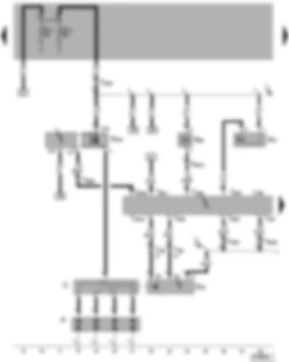
Wiring Diagram VW THE BEETLE 1997 - Battery - Starter - Generator (GEN) - Voltage Regulator (VR) - Ignition/Starter Switch - Generator (GEN) Warning Light - Engine Compartment Light

| A | Battery |
| B | Starter |
| C | Generator (GEN) |
| C1 | Voltage Regulator (VR) |
| D | Ignition/Starter Switch |
| K2 | Generator (GEN) Warning Light |
| L29 | Engine Compartment Light |
| S10 | Fuse on fuse/relay panel |
| T8 | 8-Pin Connector near to Digifant Engine Control Module (ECM) |
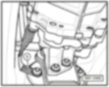
| 1 | Ground strap, battery to body |
| 30 | Ground connection, -1-, beside fuse/relay panel |
| D97 | Wire connection (50), in engine compartment wiring harness, right |
| G1 | Plus connection, in Digifant Multiport Fuel Injection (MFI) wiring harness |
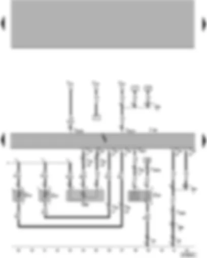
Wiring Diagram VW THE BEETLE 1997 - Ignition Coil - Camshaft Position (CMP) Sensor - Manifold Absolute Pressure (MAP) Sensor - Idle Air Control (IAC) Valve - Evaporative Emission (EVAP) Canister Purge Regulator Valve.
| G40 | Camshaft Position (CMP) Sensor |
| G71 | Manifold Absolute Pressure (MAP) Sensor |
| J169 | Digifant Engine Control Module (ECM) |
| N71 | Idle Air Control (IAC) Valve |
| N80 | Evaporative Emission (EVAP) Canister Purge Regulator Valve |
| N152 | Ignition Coil |
| O | Ignition Distributor |
| P | Spark Plug Connectors |
| T25 | 25-Pin Connector below rear seat, left |
| T28 | 28-Pin Connector in engine compartment, left |
| 94 | Ground connection -1-, in Digifant Multiport Fuel Injection (MFI) wiring harness |
| G6 | Plus connection (15), in Digifant Multiport Fuel Injection (MFI) wiring harness |
Wiring Diagram VW THE BEETLE 1997 - Heated Oxygen Sensor (HO2S) - Intake Air Temperature (IAT) Sensor - Digifant Engine Control Module (ECM)
| G39 | Heated Oxygen Sensor (HO2S) |
| G42 | Intake Air Temperature (IAT) Sensor |
| G27 | Sensor for engine temperature |
| G88 | Throttle Position (TP) Sensor |
| J169 | Digifant Engine Control Module (ECM) |
| T3 | 3-Pin Connector in engine compartment (OBD) |
| T25 | 25-Pin Connector below rear seat, left |
| T28 | 28-Pin Connector in engine compartment, left |
| 18 | Ground connection, on engine block |
| 94A | Ground connection -1-, in Digifant Multiport Fuel Injection (MFI) wiring harness |
| 94B | Ground connection -1-, in Digifant Multiport Fuel Injection (MFI) wiring harness |
| D50 | Ground connection -1-, in Digifant Multiport Fuel Injection (MFI) wiring harness |
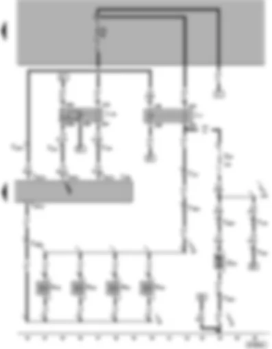
Wiring Diagram VW THE BEETLE 1997 - Transfer Fuel Pump (FP) - Fuel Pump (FP) Relay - Fuel Pump (FP) Fuse - Digifant Engine Control Module (ECM) Power Supply Relay
| G23 | Transfer Fuel Pump (FP) |
| J17 | Fuel Pump (FP) Relay |
| J169 | Digifant Engine Control Module (ECM) |
| J176 | Digifant Engine Control Module (ECM) Power Supply Relay |
| N30 | Cylinder 1 Fuel Injector |
| N31 | Cylinder 2 Fuel Injector |
| N32 | Cylinder 3 Fuel Injector |
| N33 | Cylinder 4 Fuel Injector |
| S81 | Fuel Pump (FP) Fuse |
| T2 | Double Connector behind instrument panel |
| T2a | Double Connector behind instrument panel |
| T2b | Double Connector under fuel tank |
| T4 | 4-Pin Connector behind instrument panel |
| T8 | 8-Pin Connector behind instrument panel |
| T25 | 25-Pin Connector below rear seat, left |
| T28 | 28-Pin Connector in engine compartment, left |
| 30 | Ground connection, -1-, beside fuse/relay panel |
| G3 | plus connection, in injector wiring harness |
| G4 | wire connection, in injector wiring harness |
| D51 | plus connection (15), in engine compartment wiring harness |
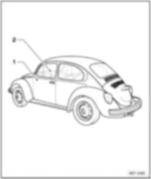
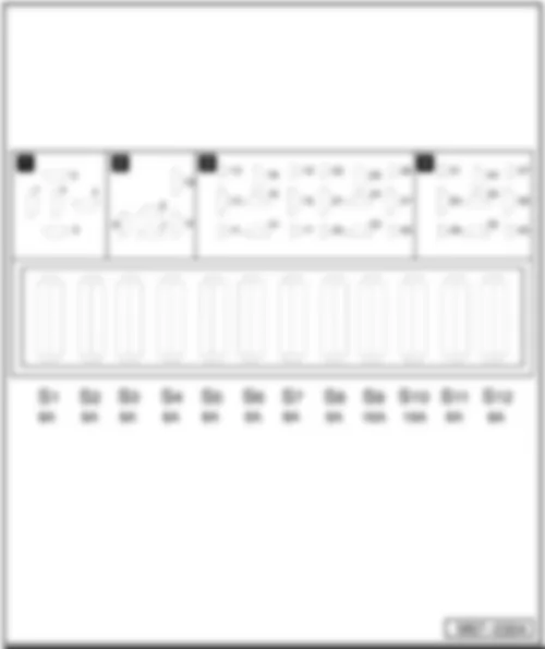
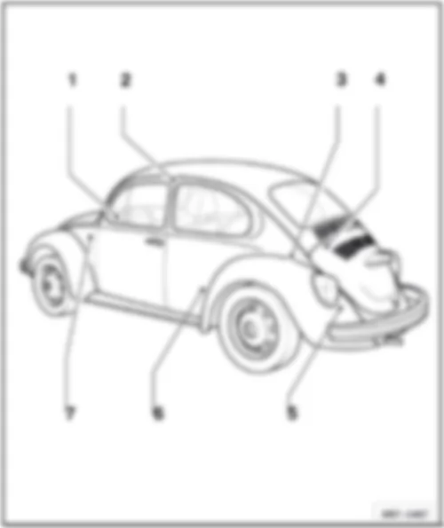
VW THE BEETLE 1997 Overview of fuses
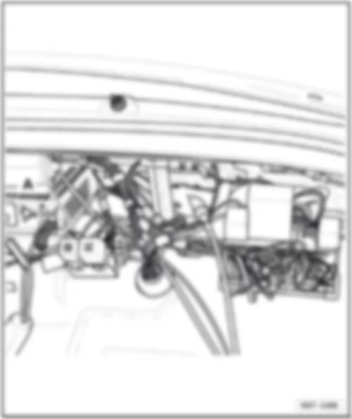
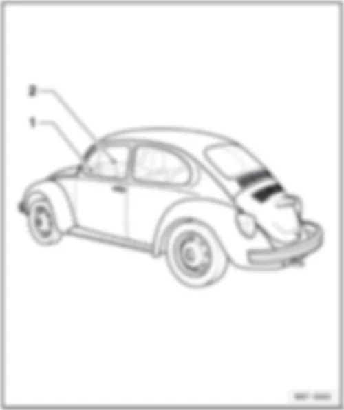
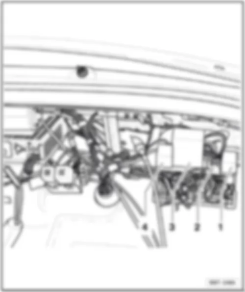
| 1 - | v Fuse on fuse holder, on left under dash panel, in vehicle interior |
| q | Location, from October 1998 → page 802/2 |
| q | Position of fuses, from October 1998 → page 802/3 |
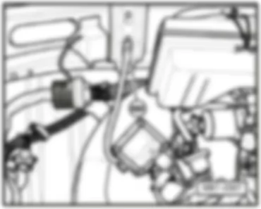
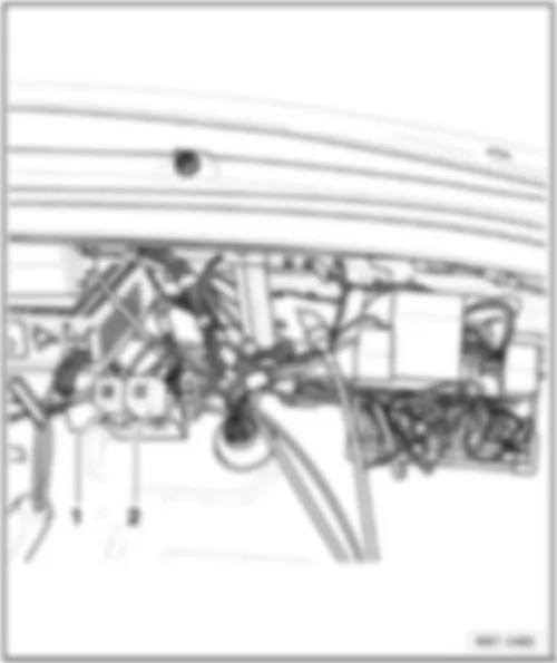
| 2 - | Fuses on relay carrier, behind dash panel, centre, in luggage compartment |
| q | Location → page 802/5 |
| 802/1 | Fitting Locations | No. 802 / 2 |
| Fuse in fuse holder, under dash panel, from October 1998 |
| 802/1 | Fitting Locations | No. 802 / 3 |
| Position of fuses in fuse holder, from October 1998 |
| No. | Current Flow Diagram designation | Nominal value | Function/component | Terminal | ||
| 1 | - | S1 - Fuses in central electrics | 58 | - | E1 - Light switch (left side repeater turn signal) J85-Alarm system control unit M5 - Front left turn signal bulb M18 - Left side repeater turn signal bulb M21 - Left brake and tail light bulb | 8A |
| 2 | - | S2 - Fuses in central electrics | 58 | E1 - Light switch (right side repeater turn signal) J85-Alarm system control unit M5 - Front left turn signal bulb M18 - Left side repeater turn signal bulb M22 - Right brake and tail light bulb X - number plate light | 8A | |
| 3 | - | S3 - Fuses in central electrics | 56b | L1 - Left headlight twin filament bulb/left sealed beam insert L17 - Left sealed beam insert, main beam | 8A | |
| 4 | - | S4 - Fuses in central electrics | 56b | L2 - Right headlight twin filament bulb/right sealed beam insert L18 - Right sealed beam insert, main beam E4 - Headlight dipper/flasher switch | 8A | |
| 5 | - | S5 - Fuses in central electrics | 56a | - | L2 - Right headlight twin filament bulb/right sealed beam insert L18 - Right sealed beam insert, main beam K1 - Main beam warning lamp | 8A |
| 6 | - | S6 - Fuses in central electrics | 56a | - | L1 - Left headlight twin filament bulb/left sealed beam insert L17 - Left sealed beam insert, main beam E4 - Headlight dipper/flasher switch | 8A |
| 802/1 | Fitting Locations | No. 802 / 4 |
| No. | Current Flow Diagram designation | Nominal value | Function/component | Terminal | ||
| 7 | - | S7 - Fuses in central electrics | K | - | R - Radio W16 - Left interior light J17 - Fuel pump relay J85-Alarm system control unit J176 - Current supply relay for Digifant control unit | 8A |
| 8 | - | S8 - Fuses in central electrics | 30 | - | D-Ignition/starter switch T3 - Self-diagnosis connection (T3/3) F - Brake light switch | 8A |
| 9 | - | S9 - Fuses in central electrics | 30 | - | E1 - Lighting switch E3 - Hazard warning light switch E4 - Headlight dipper/flasher switch | 16A |
| 10 | - | S10 - Fuses in central electrics | X | - | D-Ignition/starter switch H1 - Dual tone horn L9 - Light switch illumination bulb V - Windscreen wiper motor J31-Automatic intermittent wash and wipe relay | 16A |
| 11 | - | S11 - Fuses in central electrics | 15 | - | D-Ignition/starter switch K - Dash panel insert F4 - Reversing light switch J17 - Fuel pump relay J85-Alarm system control unit J176 - Current supply relay for Digifant control unit | 8A |
| 12 | - | S12 - Fuses in central electrics | 15 | - | E3 - Hazard warning light switch N71 - Idling speed stabilisation valve N157 - Ignition transformer output stage R - Radio | 8A |
| 802/1 | Fitting Locations | No. 802 / 5 |
| Fuses on relay carrier |
| A - | Fuel pump fuse (15A) -S81- |

 Deutsch
 English
 English
 Español
 Français
 Nederlands

