AUTOMOTIVE ELECTRICIANS PORTAL

VW FOX 2010 — 1.4l diesel engine, BNM,(F6G) . Wiring diagrams, Pin Connector, Location

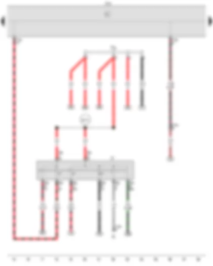
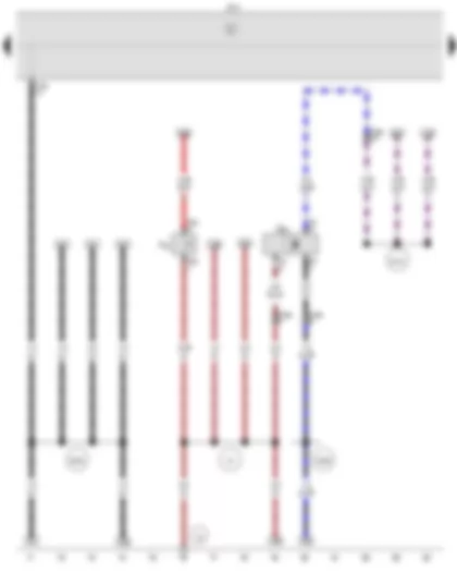
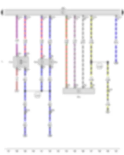
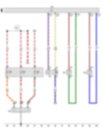
Wiring Diagram VW FOX 2010 - Battery - Starter - Alternator - Voltage regulator - Onboard supply control unit


Wiring Diagram  VW FOX 2010 - Battery - Starter - Alternator - Voltage regulator - Onboard supply control unit https://portal-diagnostov.com/license.html
https://portal-diagnostov.com/license.html Automotive Electricians Portal FZCO Automotive Electricians Portal FZCO
Download PDF file
A Battery
B Starter
C Alternator
C1 Voltage regulator
BRA5R0059808#BTJ519">J519BRA5R0059808#BTJ519"> Onboard supply control unitBRA5R0059808#BTJ519
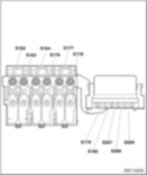
S162 Fuse 1 (30), in battery fuse holder
S163 Fuse 2 (30), in battery fuse holder
S176 Fuse 4 (30), in battery fuse holder
S180 Fuse 8 (30), in battery fuse holder
T1j Single connector
T2ak 2-pin connector, on left in engine compartment
T2ar 2-pin connector
T6g 6-pin connector, on left in plenum chamber
T11c 11-pin connector, on left in plenum chamber
T18b 18-pin connector
BRA5R0059805#VB1">  1 BRA5R0059805#VB1"> Earth strap, battery - bodyBRA5R0059805#VB1
BRA5R0059805#VB49">  49 BRA5R0059805#VB49"> Earth point, near ..., near batteryBRA5R0059805#VB49
  507 Threaded connection (30), on battery fuse holder

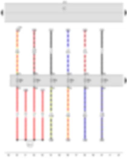
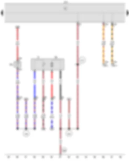
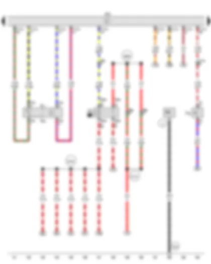
Wiring Diagram VW FOX 2010 - Ignition/starter switch - Onboard supply control unit - Terminal 30 wiring junction


Wiring Diagram  VW FOX 2010 - Ignition/starter switch - Onboard supply control unit - Terminal 30 wiring junction https://portal-diagnostov.com/license.html
https://portal-diagnostov.com/license.html Automotive Electricians Portal FZCO Automotive Electricians Portal FZCO
Получить доступ ко всем электросхемам автомобиляDownload PDF file
D Ignition/starter switch
E1 Light switch
BRA5R0059808#BTJ519">J519BRA5R0059808#BTJ519"> Onboard supply control unitBRA5R0059808#BTJ519
T8a 8-pin connector
T11b 11-pin connector, on left in plenum chamber
T12a 12-pin connector
T18b 18-pin connector
TV2 Terminal 30 wiring junction
  B170 Positive connection 2 (30), in interior wiring harness

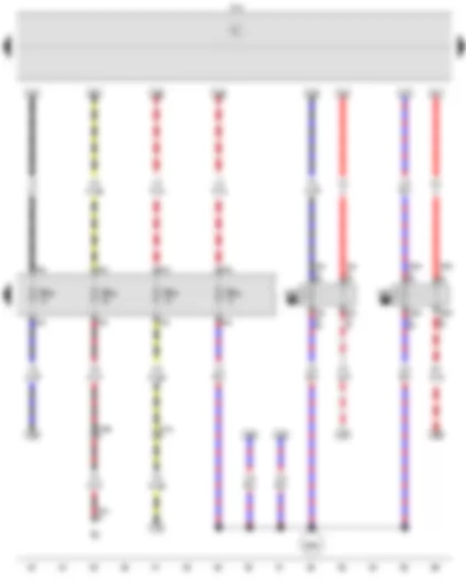
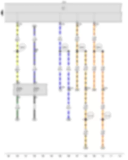
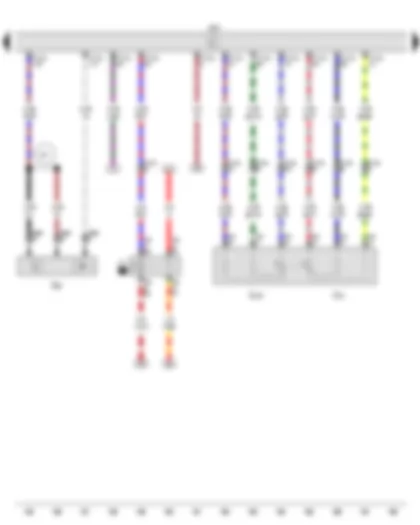
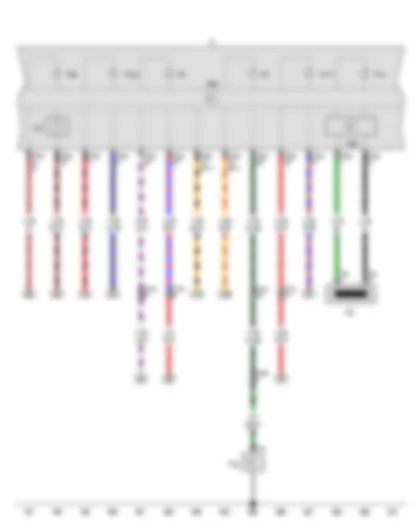
Wiring Diagram VW FOX 2010 - Onboard supply control unit


Wiring Diagram  VW FOX 2010 - Onboard supply control unit https://portal-diagnostov.com/license.html
https://portal-diagnostov.com/license.html Automotive Electricians Portal FZCO Automotive Electricians Portal FZCO
Получить доступ ко всем электросхемам автомобиляDownload PDF file
BRA5R0059808#BTJ519">J519BRA5R0059808#BTJ519"> Onboard supply control unitBRA5R0059808#BTJ519
SB27 Fuse 27 on fuse holder B
SB28 Fuse 28 on fuse holder B
SB30 Fuse 30 on fuse holder B
SB33 Fuse 33 on fuse holder B
SB34 Fuse 34 on fuse holder B
SB38 Fuse 38 on fuse holder B
T16a 16-pin connector
  B172 Positive connection 4 (30), in interior wiring harness
*Diagnostic connection

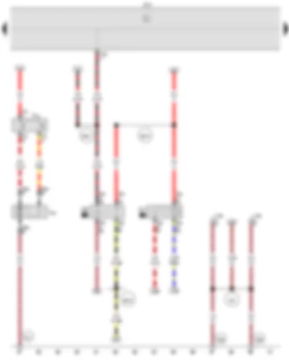
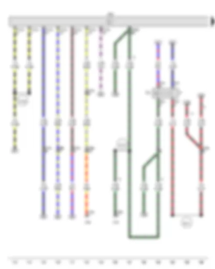
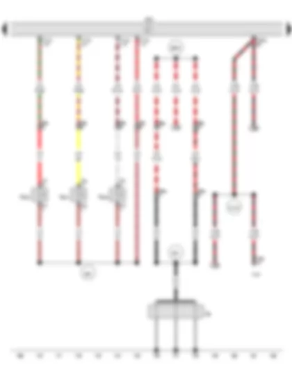
Wiring Diagram VW FOX 2010 - Low heat output relay - High heat output relay - Onboard supply control unit


Wiring Diagram  VW FOX 2010 - Low heat output relay - High heat output relay - Onboard supply control unit https://portal-diagnostov.com/license.html
https://portal-diagnostov.com/license.html Automotive Electricians Portal FZCO Automotive Electricians Portal FZCO
Получить доступ ко всем электросхемам автомобиляDownload PDF file
E9 Fresh air blower switch
J359 Low heat output relay
J360 High heat output relay
BRA5R0059808#BTJ519">J519BRA5R0059808#BTJ519"> Onboard supply control unitBRA5R0059808#BTJ519
SB40 Fuse 40 on fuse holder B
SB42 Fuse 42 on fuse holder B
SB44 Fuse 44 on fuse holder B
SB45 Fuse 45 on fuse holder B
T5m 5-pin connector
T6ab 6-pin connector
T9p 9-pin connector
T10a 10-pin connector, behind dash panel, right
T11c 11-pin connector, on left in plenum chamber
  B599 Positive connection 3 (87a), in interior wiring harness

Wiring Diagram VW FOX 2010 - Radiator fan thermal switch - X-contact relief relay - Terminal 30 voltage supply relay - Onboard supply control unit - Right radiator fan


Wiring Diagram  VW FOX 2010 - Radiator fan thermal switch - X-contact relief relay - Terminal 30 voltage supply relay - Onboard supply control unit - Right radiator fan https://portal-diagnostov.com/license.html
https://portal-diagnostov.com/license.html Automotive Electricians Portal FZCO Automotive Electricians Portal FZCO
Получить доступ ко всем электросхемам автомобиляDownload PDF file
F18 Radiator fan thermal switch
J59 X-contact relief relay
J317 Terminal 30 voltage supply relay
BRA5R0059808#BTJ519">J519BRA5R0059808#BTJ519"> Onboard supply control unitBRA5R0059808#BTJ519
T3m 3-pin connector, on radiator fan
T3y 3-pin connector
T6d 6-pin connector
T9q 9-pin connector
T16a 16-pin connector
T18b 18-pin connector
V35 Right radiator fan
  297 Earth connection 12, in interior wiring harness
BRA5R0059805#VB605">  605 BRA5R0059805#VB605"> Earth point, on top end of steering columnBRA5R0059805#VB605
BRA5R0059805#VB606">  606 BRA5R0059805#VB606"> Earth point, under the centre console near gear stickBRA5R0059805#VB606
BRA5R0059805#VB671">  671 BRA5R0059805#VB671"> Earth point 1, on front of left longitudinal memberBRA5R0059805#VB671
  B218 Positive connection 6 (30), in interior wiring harness
  B491 Positive connection (75), in interior wiring harness
  B516 Positive connection 5 (87), in interior wiring harness
*Diagnostic connection

Wiring Diagram VW FOX 2010 - Brake fluid level warning contact - Speedometer sender - Onboard supply control unit


Wiring Diagram  VW FOX 2010 - Brake fluid level warning contact - Speedometer sender - Onboard supply control unit https://portal-diagnostov.com/license.html
https://portal-diagnostov.com/license.html Automotive Electricians Portal FZCO Automotive Electricians Portal FZCO
Получить доступ ко всем электросхемам автомобиляDownload PDF file
F34 Brake fluid level warning contact
G22 Speedometer sender
BRA5R0059808#BTJ519">J519BRA5R0059808#BTJ519"> Onboard supply control unitBRA5R0059808#BTJ519
T2ai 2-pin connector
T3i 3-pin connector
T14a 14-pin connector, on left in engine compartment
T18b 18-pin connector
BRA5R0059805#VB12">  12 BRA5R0059805#VB12"> Earth point, on left in engine compartmentBRA5R0059805#VB12
  131 Earth connection 2, in engine compartment wiring harness
  B163 Positive connection 1 (15), in interior wiring harness
  D191 Speed sender connection, in engine compartment wiring harness
  D200 Positive connection 3 (15a), in engine compartment wiring harness

Wiring Diagram VW FOX 2010 - Fuel gauge sender - Fuel system pressurisation pump - Coolant shortage indicator sender - Onboard supply control unit


Wiring Diagram  VW FOX 2010 - Fuel gauge sender - Fuel system pressurisation pump - Coolant shortage indicator sender - Onboard supply control unit https://portal-diagnostov.com/license.html
https://portal-diagnostov.com/license.html Automotive Electricians Portal FZCO Automotive Electricians Portal FZCO
Получить доступ ко всем электросхемам автомобиляDownload PDF file
G Fuel gauge sender
G6 Fuel system pressurisation pump
G32 Coolant shortage indicator sender
BRA5R0059808#BTJ519">J519BRA5R0059808#BTJ519"> Onboard supply control unitBRA5R0059808#BTJ519
T2bk 2-pin connector
T4j 4-pin connector
T5n 5-pin connector
T11a 11-pin connector, on left in plenum chamber
T16a 16-pin connector
T18b 18-pin connector
  238 Earth connection 1, in interior wiring harness
  278 Earth connection 4, in interior wiring harness
  459 Earth connection 15, in interior wiring harness
BRA5R0059805#VB606">  606 BRA5R0059805#VB606"> Earth point, under the centre console near gear stickBRA5R0059805#VB606
*Diagnostic connection

Wiring Diagram VW FOX 2010 - Onboard supply control unit


Wiring Diagram  VW FOX 2010 - Onboard supply control unit https://portal-diagnostov.com/license.html
https://portal-diagnostov.com/license.html Automotive Electricians Portal FZCO Automotive Electricians Portal FZCO
Получить доступ ко всем электросхемам автомобиляDownload PDF file
BRA5R0059808#BTJ519">J519BRA5R0059808#BTJ519"> Onboard supply control unitBRA5R0059808#BTJ519
SC2 Fuse 2 on fuse holder C
SC3 Fuse 3 on fuse holder C
T9k 9-pin connector, on left in plenum chamber
T11a 11-pin connector, on left in plenum chamber
T11d 11-pin connector, on left in plenum chamber
T16a 16-pin connector
T16b 16-pin connector
T18b 18-pin connector
  B229 Connection (high bus), in interior wiring harness
  B230 Connection (low bus), in interior wiring harness
  B500 Connection (86s), in interior wiring harness
  B590 K-diagnosis wire connection, in interior wiring harness
  D178 Connection 2 (high bus), in engine compartment wiring harness
  D179 Connection 2 (low bus), in engine compartment wiring harness
*Diagnostic connection

Wiring Diagram VW FOX 2010 - Brake light switch - Brake pedal switch - Engine control unit


Wiring Diagram  VW FOX 2010 - Brake light switch - Brake pedal switch - Engine control unit https://portal-diagnostov.com/license.html
https://portal-diagnostov.com/license.html Automotive Electricians Portal FZCO Automotive Electricians Portal FZCO
Получить доступ ко всем электросхемам автомобиляDownload PDF file
F Brake light switch
F47 Brake pedal switch
BRA5R0059808#BTJ104">J104BRA5R0059808#BTJ104"> ABS control unitBRA5R0059808#BTJ104
BRA5R0059808#BTJ162">J162BRA5R0059808#BTJ162"> Heater control unitBRA5R0059808#BTJ162
BRA5R0059808#BTJ623">J623BRA5R0059808#BTJ623"> Engine control unitBRA5R0059808#BTJ623
T4m 4-pin connector
T9k 9-pin connector, on left in plenum chamber
T10a 10-pin connector, behind dash panel, right
T11a 11-pin connector, on left in plenum chamber
T11d 11-pin connector, on left in plenum chamber
T16d 16-pin connector
T38b 38-pin connector
T121a 121-pin connector
  B131 Connection (54), in interior wiring harness
  D101 Connection 1 in engine compartment wiring harness
  D182 Connection 3 (87a) in engine compartment wiring harness
*Only models with no electronic stabilisation program (ESP)
*2Only models with electronic stabilisation program (ESP)
*3Only models with ABS

Wiring Diagram VW FOX 2010 - Air mass meter - Engine control unit - Exhaust gas recirculation valve - Charge pressure control solenoid valve - Intake manifold flap motor


Wiring Diagram  VW FOX 2010 - Air mass meter - Engine control unit - Exhaust gas recirculation valve - Charge pressure control solenoid valve - Intake manifold flap motor https://portal-diagnostov.com/license.html
https://portal-diagnostov.com/license.html Automotive Electricians Portal FZCO Automotive Electricians Portal FZCO
Получить доступ ко всем электросхемам автомобиляDownload PDF file
G70 Air mass meter
BRA5R0059808#BTJ623">J623BRA5R0059808#BTJ623"> Engine control unitBRA5R0059808#BTJ623
N18 Exhaust gas recirculation valve
N75 Charge pressure control solenoid valve
T4ah 4-pin connector
T5q 5-pin connector
T6z 6-pin connector
T11a 11-pin connector, on left in plenum chamber
T11b 11-pin connector, on left in plenum chamber
T14a 14-pin connector, on left in engine compartment
T121a 121-pin connector
V157 Intake manifold flap motor
  D136 Positive connection 2 (15a), in engine compartment wiring harness
  D183 Connection 4 (87a) in engine compartment wiring harness

Wiring Diagram VW FOX 2010 - Clutch pedal switch - Intake air temperature sender - Intake manifold pressure sender - Glow plug relay - Engine control unit - Gearbox


Wiring Diagram  VW FOX 2010 - Clutch pedal switch - Intake air temperature sender - Intake manifold pressure sender - Glow plug relay - Engine control unit - Gearbox https://portal-diagnostov.com/license.html
https://portal-diagnostov.com/license.html Automotive Electricians Portal FZCO Automotive Electricians Portal FZCO
Получить доступ ко всем электросхемам автомобиляDownload PDF file
F36 Clutch pedal switch
G42 Intake air temperature sender
G71 Intake manifold pressure sender
J52 Glow plug relay
BRA5R0059808#BTJ623">J623BRA5R0059808#BTJ623"> Engine control unitBRA5R0059808#BTJ623
NX1 Gearbox
T4ai 4-pin connector
T4l 4-pin connector
T6aa 6-pin connector
T6g 6-pin connector, on left in plenum chamber
T9k 9-pin connector, on left in plenum chamber
T11b 11-pin connector, on left in plenum chamber
T121a 121-pin connector
  2 Earth strap, gearbox - body
  672 Earth point 2, on front of left longitudinal member
  B146 Positive connection 1 (87), in interior wiring harness
  B598 Positive connection 11 (30a), in interior wiring harness
  D104 Positive connection 2 (30a), in engine compartment wiring harness

Wiring Diagram VW FOX 2010 - Engine speed sender - Accelerator position sender - Accelerator position sender 2 - Fuel pump relay - Engine control unit


Wiring Diagram  VW FOX 2010 - Engine speed sender - Accelerator position sender - Accelerator position sender 2 - Fuel pump relay - Engine control unit https://portal-diagnostov.com/license.html
https://portal-diagnostov.com/license.html Automotive Electricians Portal FZCO Automotive Electricians Portal FZCO
Получить доступ ко всем электросхемам автомобиляDownload PDF file
G28 Engine speed sender
G79 Accelerator position sender
G185 Accelerator position sender 2
J17 Fuel pump relay
BRA5R0059808#BTJ623">J623BRA5R0059808#BTJ623"> Engine control unitBRA5R0059808#BTJ623
T3af 3-pin connector
T6f 6-pin connector
T9r 9-pin connector
T11b 11-pin connector, on left in plenum chamber
T121a 121-pin connector
  F27 Connection (screening), in diesel direct injection wiring harness

Wiring Diagram VW FOX 2010 - Engine control unit - Unit injector valve - No. 1 cyl. - Unit injector valve - No. 2 cyl. - Unit injector valve - No. 3 cyl. - Engine glow plug


Wiring Diagram  VW FOX 2010 - Engine control unit - Unit injector valve - No. 1 cyl. - Unit injector valve - No. 2 cyl. - Unit injector valve - No. 3 cyl. - Engine glow plug https://portal-diagnostov.com/license.html
https://portal-diagnostov.com/license.html Automotive Electricians Portal FZCO Automotive Electricians Portal FZCO
Получить доступ ко всем электросхемам автомобиляDownload PDF file
BRA5R0059808#BTJ104">J104BRA5R0059808#BTJ104"> ABS control unitBRA5R0059808#BTJ104
BRA5R0059808#BTJ623">J623BRA5R0059808#BTJ623"> Engine control unitBRA5R0059808#BTJ623
N240 Unit injector valve, No. 1 cyl.
N241 Unit injector valve, No. 2 cyl.
N242 Unit injector valve, No. 3 cyl.
Q6 Engine glow plug
T2bx 2-pin connector, on left in engine compartment
T2f 2-pin connector
T2g 2-pin connector
T2h 2-pin connector
T6g 6-pin connector, on left in plenum chamber
T8k 8-pin connector, in engine compartment
T38a 38-pin connector
T121a 121-pin connector
  B600 Positive connection 4 (87a), in interior wiring harness
  D102 Connection 2 in engine compartment wiring harness
  E43 Connection (87), in injection system wiring harness
  E55 Connection 2 (injectors), in injection system wiring harness
*Only models with ABS

Wiring Diagram VW FOX 2010 - Hall sender - Coolant temperature sender - Fuel temperature sender - Engine control unit - Auxiliary air heater element


Wiring Diagram  VW FOX 2010 - Hall sender - Coolant temperature sender - Fuel temperature sender - Engine control unit - Auxiliary air heater element https://portal-diagnostov.com/license.html
https://portal-diagnostov.com/license.html Automotive Electricians Portal FZCO Automotive Electricians Portal FZCO
Получить доступ ко всем электросхемам автомобиляDownload PDF file
G40 Hall sender
G62 Coolant temperature sender
G81 Fuel temperature sender
BRA5R0059808#BTJ623">J623BRA5R0059808#BTJ623"> Engine control unitBRA5R0059808#BTJ623
BRA5R0059806#BTS276">S276BRA5R0059806#BTS276"> Heater element fuse 1BRA5R0059806#BTS276
BRA5R0059806#BTS277">S277BRA5R0059806#BTS277"> Heater element fuse 2BRA5R0059806#BTS277
BRA5R0059806#BTS278">S278BRA5R0059806#BTS278"> Heater element fuse 3BRA5R0059806#BTS278
T2bm 2-pin connector
T2bw 2-pin connector
T3n 3-pin connector
T3z 3-pin connector
T121a 121-pin connector
Z35 Auxiliary air heater element
  B217 Connection (auxiliary heater), in interior wiring harness

Wiring Diagram VW FOX 2010 - Immobiliser reader coil - Oil pressure switch - Fuel gauge - Control unit in dash panel insert - Immobiliser control unit - Dash panel insert - Alternator warning lamp - Oil pressure warning lamp - Handbrake warning lamp


Wiring Diagram  VW FOX 2010 - Immobiliser reader coil - Oil pressure switch - Fuel gauge - Control unit in dash panel insert - Immobiliser control unit - Dash panel insert - Alternator warning lamp - Oil pressure warning lamp - Handbrake warning lamp https://portal-diagnostov.com/license.html
https://portal-diagnostov.com/license.html Automotive Electricians Portal FZCO Automotive Electricians Portal FZCO
Получить доступ ко всем электросхемам автомобиляDownload PDF file
D2 Immobiliser reader coil
F22 Oil pressure switch
G1 Fuel gauge
BRA5R0059808#BTJ285">J285BRA5R0059808#BTJ285"> Control unit in dash panel insertBRA5R0059808#BTJ285
J362 Immobiliser control unit
K Dash panel insert
K2 Alternator warning lamp
K3 Oil pressure warning lamp
K14 Handbrake warning lamp
K36 Coolant shortage warning lamp
K105 Reserve fuel warning lamp
K117 Immobiliser warning lamp
T1a Single connector
T2s 2-pin connector
T11a 11-pin connector, on left in plenum chamber
T11c 11-pin connector, on left in plenum chamber
T14a 14-pin connector, on left in engine compartment
T32a 32-pin connector


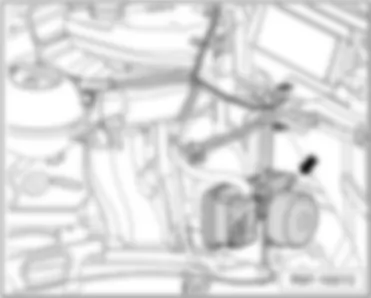
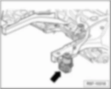
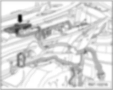
VW FOX 2010 ABS control unit J104

ABS control unit - J104 -
   
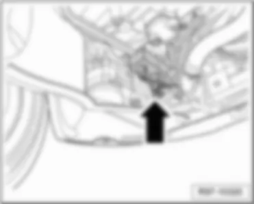
Location:
–  in engine compartment, right -arrow-
 
VW FOX 2010 ABS control unit   J104 https://portal-diagnostov.com/license.html
https://portal-diagnostov.com/license.html Automotive Electricians Portal FZCO Automotive Electricians Portal FZCO
Получить доступ ко всем электросхемам автомобиляDownload PDF file
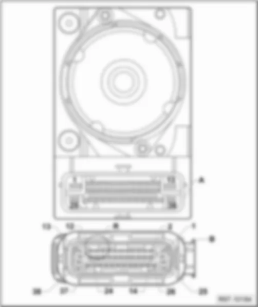
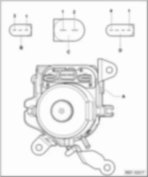
Designation of connector:
VW FOX 2010 ABS control unit   J104 https://portal-diagnostov.com/license.html
https://portal-diagnostov.com/license.html Automotive Electricians Portal FZCO Automotive Electricians Portal FZCO
Получить доступ ко всем электросхемам автомобиляDownload PDF file
A  -  ABS control unit - J104 -
B  -  38-pin connector - T38a -
B  -  38-pin connector - T38b -
q   for models with EPS, ASR and ESP only

ABS control unit (right-hand drive) - J104 -
   
Location:
–  in engine compartment, left -arrow-
 
VW FOX 2010 ABS control unit   J104 https://portal-diagnostov.com/license.html
https://portal-diagnostov.com/license.html Automotive Electricians Portal FZCO Automotive Electricians Portal FZCO
Получить доступ ко всем электросхемам автомобиляDownload PDF file
Designation of connector:
VW FOX 2010 ABS control unit   J104 https://portal-diagnostov.com/license.html
https://portal-diagnostov.com/license.html Automotive Electricians Portal FZCO Automotive Electricians Portal FZCO
Получить доступ ко всем электросхемам автомобиляDownload PDF file
A  -  ABS control unit - J104 -
B  -  38-pin connector - T38a -
B  -  38-pin connector - T38b -
q   for models with EPS, ASR and ESP only

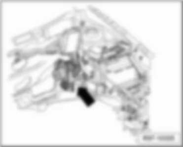
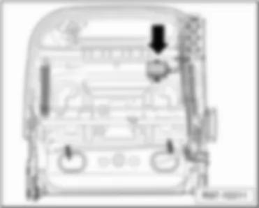
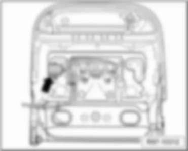
Heated driver seat control unit - J131 -
   
Location:
–  under driver seat - arrow -
 
VW FOX 2010 ABS control unit   J104 https://portal-diagnostov.com/license.html
https://portal-diagnostov.com/license.html Automotive Electricians Portal FZCO Automotive Electricians Portal FZCO
Получить доступ ко всем электросхемам автомобиляDownload PDF file
Designation of connector:
VW FOX 2010 ABS control unit   J104 https://portal-diagnostov.com/license.html
https://portal-diagnostov.com/license.html Automotive Electricians Portal FZCO Automotive Electricians Portal FZCO
Получить доступ ко всем электросхемам автомобиляDownload PDF file
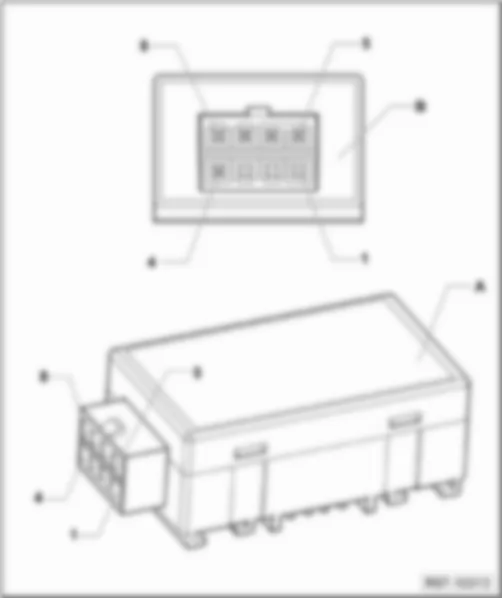
A  -  Heated driver seat control unit - J131 -
B  -  8-pin connector - T8n -

Heated front passenger seat control unit - J132 -
   
Location:
–  under front passenger seat - arrow -
 
VW FOX 2010 ABS control unit   J104 https://portal-diagnostov.com/license.html
https://portal-diagnostov.com/license.html Automotive Electricians Portal FZCO Automotive Electricians Portal FZCO
Получить доступ ко всем электросхемам автомобиляDownload PDF file
Designation of connector:
VW FOX 2010 ABS control unit   J104 https://portal-diagnostov.com/license.html
https://portal-diagnostov.com/license.html Automotive Electricians Portal FZCO Automotive Electricians Portal FZCO
Получить доступ ко всем электросхемам автомобиляDownload PDF file
A  -  Heated front passenger seat control unit - J132 -
B  -  8-pin connector - T8m -

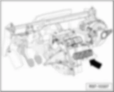
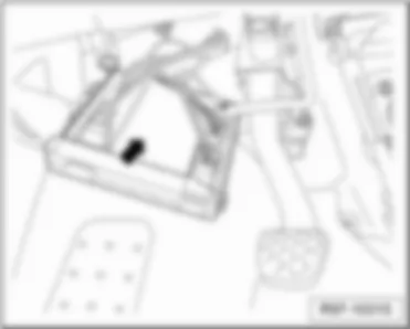
Heater control unit - J162 -
   
Location:
–  Above the front centre console -arrow-
 
VW FOX 2010 ABS control unit   J104 https://portal-diagnostov.com/license.html
https://portal-diagnostov.com/license.html Automotive Electricians Portal FZCO Automotive Electricians Portal FZCO
Получить доступ ко всем электросхемам автомобиляDownload PDF file
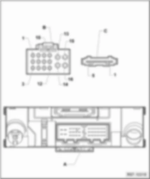
Designation of connector:
VW FOX 2010 ABS control unit   J104 https://portal-diagnostov.com/license.html
https://portal-diagnostov.com/license.html Automotive Electricians Portal FZCO Automotive Electricians Portal FZCO
Получить доступ ко всем электросхемам автомобиляDownload PDF file
A  -  Heater control unit - J162 -
B  -  16-pin connector - T16d -
C  -  5-pin connector - T5m -

Airbag control unit - J234 -
   
Location:
–  under the centre console near selector lever -arrow-
 
VW FOX 2010 ABS control unit   J104 https://portal-diagnostov.com/license.html
https://portal-diagnostov.com/license.html Automotive Electricians Portal FZCO Automotive Electricians Portal FZCO
Получить доступ ко всем электросхемам автомобиляDownload PDF file
Designation of connector:
VW FOX 2010 ABS control unit   J104 https://portal-diagnostov.com/license.html
https://portal-diagnostov.com/license.html Automotive Electricians Portal FZCO Automotive Electricians Portal FZCO
Получить доступ ко всем электросхемам автомобиляDownload PDF file
A  -  Airbag control unit - J234 -
B  -  75-pin connector - T75a -

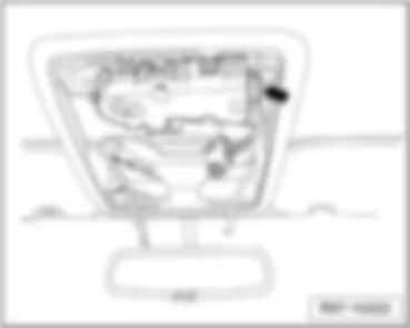
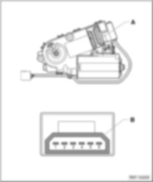
Sliding sunroof adjustment control unit - J245 -
   
Location:
–  before interior mirror, next to reading lights-arrow-
 
VW FOX 2010 ABS control unit   J104 https://portal-diagnostov.com/license.html
https://portal-diagnostov.com/license.html Automotive Electricians Portal FZCO Automotive Electricians Portal FZCO
Получить доступ ко всем электросхемам автомобиляDownload PDF file
Designation of connector:
VW FOX 2010 ABS control unit   J104 https://portal-diagnostov.com/license.html
https://portal-diagnostov.com/license.html Automotive Electricians Portal FZCO Automotive Electricians Portal FZCO
Получить доступ ко всем электросхемам автомобиляDownload PDF file
A  -  Sliding sunroof adjustment control unit - J245 -
B  -  6-pin connector - T6x -

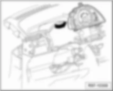
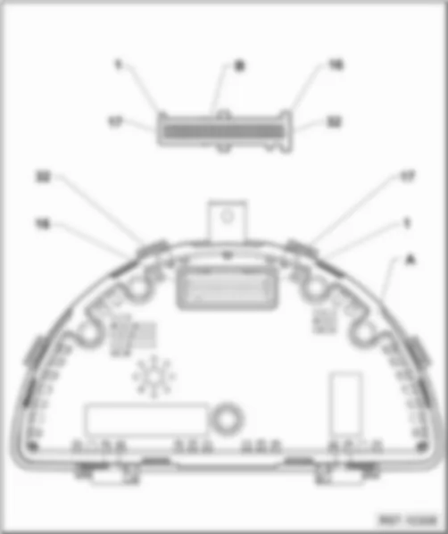
Control unit with display in dash panel insert - J285 -
   
Location:
–  Near steering column, in dash panel insert -arrow-
 
VW FOX 2010 ABS control unit   J104 https://portal-diagnostov.com/license.html
https://portal-diagnostov.com/license.html Automotive Electricians Portal FZCO Automotive Electricians Portal FZCO
Получить доступ ко всем электросхемам автомобиляDownload PDF file
Designation of connector:
VW FOX 2010 ABS control unit   J104 https://portal-diagnostov.com/license.html
https://portal-diagnostov.com/license.html Automotive Electricians Portal FZCO Automotive Electricians Portal FZCO
Получить доступ ко всем электросхемам автомобиляDownload PDF file
A  -  Control unit with display in dash panel insert - J285 -
B  -  32-pin connector - T32a -
1  -  Immobilizer reader coil
2  -  Immobilizer reader coil
3  -  Terminal 15, ignition
4  -  Terminal 30
5  -  Right side lights
6  -  Vacant
7  -  Vacant
8  -  Terminal 31
9  -  Terminal 31 for sensors
10  -  Heated rear window
11  -  Vacant
12  -  Vacant
13  -  Vacant
14  -  CAN wake up
15  -  CAN Shield
16  -  CAN-Bus high
17  -  Terminal 58d
18  -  Fog lights
19  -  Rear fog light
20  -  Terminal 58
21  -  Handbrake warning switch
22  -  Brake fluid level sender
23  -  Fuel gauge sender
24  -  Seat belt warning system
25  -  Terminal 56a, main beam
26  -  Ambient temperature indicator sender
27  -  Left side lights
28  -  Coolant shortage indicator sender
29  -  Oil level sender
30  -  Speedometer sender
31  -  Rev. counter
32  -  Terminal CAN-Bus low

Radiator fan control unit - J293 -
   
Location:
–  in engine compartment, left -arrow-
 
VW FOX 2010 ABS control unit   J104 https://portal-diagnostov.com/license.html
https://portal-diagnostov.com/license.html Automotive Electricians Portal FZCO Automotive Electricians Portal FZCO
Получить доступ ко всем электросхемам автомобиляDownload PDF file
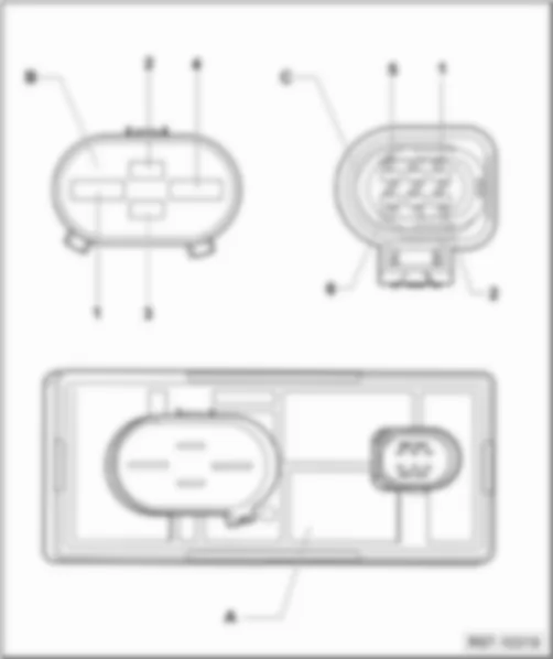
Designation of connector:
VW FOX 2010 ABS control unit   J104 https://portal-diagnostov.com/license.html
https://portal-diagnostov.com/license.html Automotive Electricians Portal FZCO Automotive Electricians Portal FZCO
Получить доступ ко всем электросхемам автомобиляDownload PDF file
A  -  Radiator fan control unit - J293 -
B  -  4-pin connector - T4am -
C  -  6-pin connector - T6al -

Air conditioning system control unit - J301 -
   
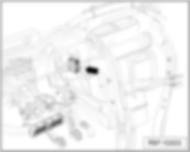
Location:
–  Above the front centre console -arrow-
 
VW FOX 2010 ABS control unit   J104 https://portal-diagnostov.com/license.html
https://portal-diagnostov.com/license.html Automotive Electricians Portal FZCO Automotive Electricians Portal FZCO
Получить доступ ко всем электросхемам автомобиляDownload PDF file
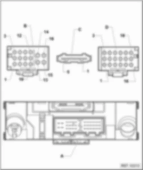
Designation of connector:
VW FOX 2010 ABS control unit   J104 https://portal-diagnostov.com/license.html
https://portal-diagnostov.com/license.html Automotive Electricians Portal FZCO Automotive Electricians Portal FZCO
Получить доступ ко всем электросхемам автомобиляDownload PDF file
A  -  Air conditioning system control unit - J301 -
B  -  16-pin connector - T16e -
C  -  5-pin connector - T5s -
D  -  18-pin connector - T18c -

Convenience system central control unit - J393 -
   
Location:
–  Behind left dash panel, next to steering column -arrow-
 
VW FOX 2010 ABS control unit   J104 https://portal-diagnostov.com/license.html
https://portal-diagnostov.com/license.html Automotive Electricians Portal FZCO Automotive Electricians Portal FZCO
Получить доступ ко всем электросхемам автомобиляDownload PDF file
Designation of connector:
VW FOX 2010 ABS control unit   J104 https://portal-diagnostov.com/license.html
https://portal-diagnostov.com/license.html Automotive Electricians Portal FZCO Automotive Electricians Portal FZCO
Получить доступ ко всем электросхемам автомобиляDownload PDF file
A  -  Convenience system central control unit - J393 -
B  -  12-pin connector -T12b -
C  -  23-pin connector -T23a -
D  -  12-pin connector -T12c -

Power steering control unit - J500 -
   
Location:
–  in engine compartment, left -arrow-
 
VW FOX 2010 ABS control unit   J104 https://portal-diagnostov.com/license.html
https://portal-diagnostov.com/license.html Automotive Electricians Portal FZCO Automotive Electricians Portal FZCO
Получить доступ ко всем электросхемам автомобиляDownload PDF file
Designation of connector:
VW FOX 2010 ABS control unit   J104 https://portal-diagnostov.com/license.html
https://portal-diagnostov.com/license.html Automotive Electricians Portal FZCO Automotive Electricians Portal FZCO
Получить доступ ко всем электросхемам автомобиляDownload PDF file
A  -  Power steering control unit - J500 -
B  -  4-pin connector - T4an -
C  -  3-pin connector - T3ai -
D  -  2-pin connector - T2cf -

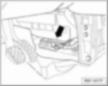
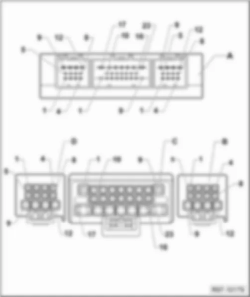
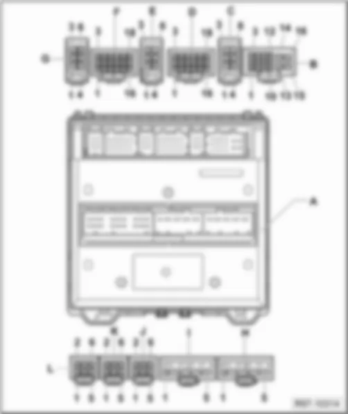
Onboard supply control unit - J519 -
   
Location:
–  Behind the dash panel, left- arrow -
 
VW FOX 2010 ABS control unit   J104 https://portal-diagnostov.com/license.html
https://portal-diagnostov.com/license.html Automotive Electricians Portal FZCO Automotive Electricians Portal FZCO
Получить доступ ко всем электросхемам автомобиляDownload PDF file
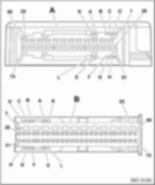
Designation of connector:
VW FOX 2010 ABS control unit   J104 https://portal-diagnostov.com/license.html
https://portal-diagnostov.com/license.html Automotive Electricians Portal FZCO Automotive Electricians Portal FZCO
Получить доступ ко всем электросхемам автомобиляDownload PDF file
A  -  Onboard supply control unit - J519 -
B  -  16-pin connector - T16b -
C  -  6-pin connector - T6 -
D  -  18-pin connector - T18b -
E  -  6-pin connector - T6 -
F  -  18-pin connector - T18a -
G  -  6-pin connector - T6s -
H  -  5-pin connector - T5n -
I  -  5-pin connector - T5p -
J  -  6-pin connector - T6ad -
K  -  6-pin connector - T6y -
L  -  6-pin connector - T6ae -

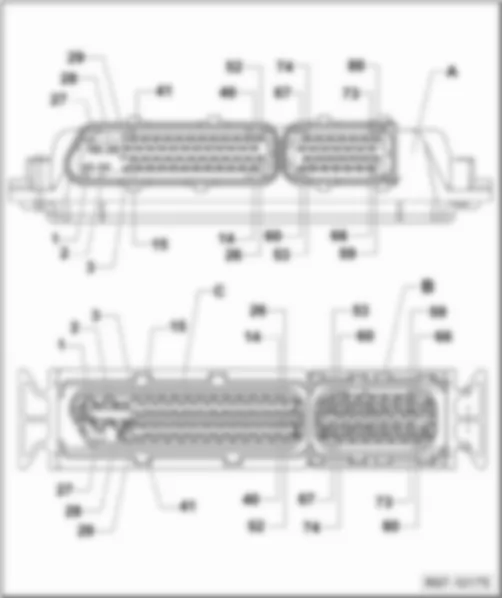
Engine control unit (80-pin) - J623 -
   
Location:
–  in engine compartment, left -arrow-
 
VW FOX 2010 ABS control unit   J104 https://portal-diagnostov.com/license.html
https://portal-diagnostov.com/license.html Automotive Electricians Portal FZCO Automotive Electricians Portal FZCO
Получить доступ ко всем электросхемам автомобиляDownload PDF file
Designation of connector:
VW FOX 2010 ABS control unit   J104 https://portal-diagnostov.com/license.html
https://portal-diagnostov.com/license.html Automotive Electricians Portal FZCO Automotive Electricians Portal FZCO
Получить доступ ко всем электросхемам автомобиляDownload PDF file
A  -  Engine control unit (80-pin) - J623 -
B / C  -  80-pin connector - T80a -

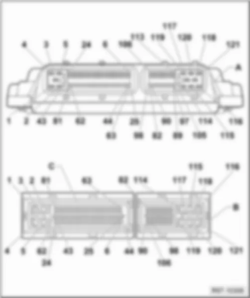
Engine control unit (121-pin) - J623 -
   
Location:
–  in left engine compartment (under radiator) -arrow-
 
VW FOX 2010 ABS control unit   J104 https://portal-diagnostov.com/license.html
https://portal-diagnostov.com/license.html Automotive Electricians Portal FZCO Automotive Electricians Portal FZCO
Получить доступ ко всем электросхемам автомобиляDownload PDF file
Designation of connector:
VW FOX 2010 ABS control unit   J104 https://portal-diagnostov.com/license.html
https://portal-diagnostov.com/license.html Automotive Electricians Portal FZCO Automotive Electricians Portal FZCO
Получить доступ ко всем электросхемам автомобиляDownload PDF file
A  -  Engine control unit (121-pin) - J623 -
B / C  -  121-pin connector - T121a -


VW FOX 2010

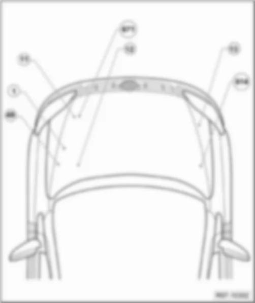
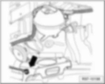
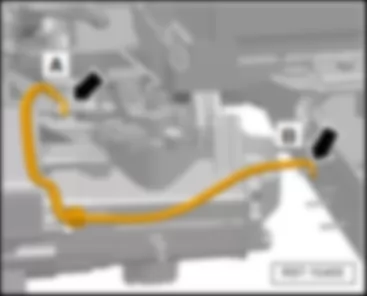
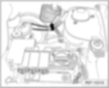
Earth strap, battery - body -arrow A -

VW FOX 2010 Earth point, in engine compartment

Earth point, in engine compartment
VW FOX 2010 Earth point, in engine compartment https://portal-diagnostov.com/license.html
https://portal-diagnostov.com/license.html Automotive Electricians Portal FZCO Automotive Electricians Portal FZCO
Получить доступ ко всем электросхемам автомобиляDownload PDF file
   1 Earth strap, battery - body
q   Location: → Reference
   11 Earth point, in battery box
q   Location: → Reference
   12 Earth point, on left in engine compartment
q   Location: → Reference
   13 Earth point, on right in engine compartment
q   Location: . → Reference
   49 Earth point, near battery
q   Location: → Reference
   614 Earth point 2, on right in engine compartment
q   Location: → Reference
   671 Earth point 1, on front of left longitudinal member
q   Location: → Reference

   
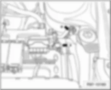
   1 Earth strap, battery - body -arrow A -
   49 Earth point, near battery -arrow B-
 
VW FOX 2010 Earth point, in engine compartment https://portal-diagnostov.com/license.html
https://portal-diagnostov.com/license.html Automotive Electricians Portal FZCO Automotive Electricians Portal FZCO
Получить доступ ко всем электросхемам автомобиляDownload PDF file
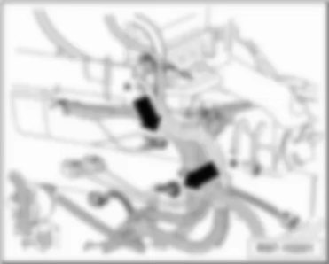
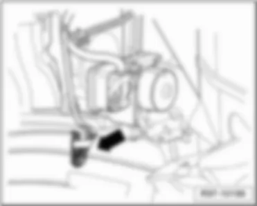
   11 Earth point, in battery box -arrow A-
   671 Earth point 1 at front of left longitudinal member -arrow B-
 
VW FOX 2010 Earth point, in engine compartment https://portal-diagnostov.com/license.html
https://portal-diagnostov.com/license.html Automotive Electricians Portal FZCO Automotive Electricians Portal FZCO
Получить доступ ко всем электросхемам автомобиляDownload PDF file
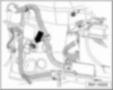
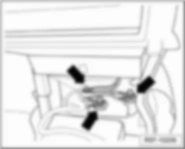
   12 Earth point, in engine compartment, left -arrow-
 
VW FOX 2010 Earth point, in engine compartment https://portal-diagnostov.com/license.html
https://portal-diagnostov.com/license.html Automotive Electricians Portal FZCO Automotive Electricians Portal FZCO
Получить доступ ко всем электросхемам автомобиляDownload PDF file
   13 Earth point, in engine compartment, right -arrow-
 
VW FOX 2010 Earth point, in engine compartment https://portal-diagnostov.com/license.html
https://portal-diagnostov.com/license.html Automotive Electricians Portal FZCO Automotive Electricians Portal FZCO
Получить доступ ко всем электросхемам автомобиляDownload PDF file
   614 Earth point 2, in engine compartment, right -arrow-
 
VW FOX 2010 Earth point, in engine compartment https://portal-diagnostov.com/license.html
https://portal-diagnostov.com/license.html Automotive Electricians Portal FZCO Automotive Electricians Portal FZCO
Получить доступ ко всем электросхемам автомобиляDownload PDF file
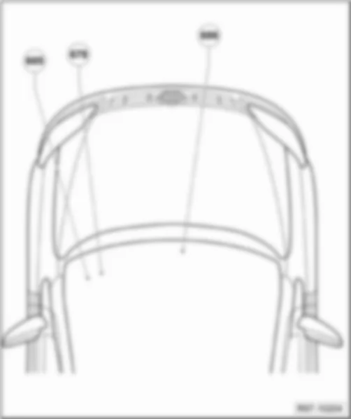
Earth points, in interior
VW FOX 2010 Earth point, in engine compartment https://portal-diagnostov.com/license.html
https://portal-diagnostov.com/license.html Automotive Electricians Portal FZCO Automotive Electricians Portal FZCO
Получить доступ ко всем электросхемам автомобиляDownload PDF file
   605 Earth point, on top end of steering column
q   Location: → Reference
   606 Earth point, under the centre console near selector lever
q   Location: → Reference
   678 Earth point, under the centre console near selector lever
q   Location: → Reference

   
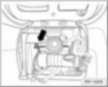
   605 Earth point, on top end of steering column -arrow-
 
VW FOX 2010 Earth point, in engine compartment https://portal-diagnostov.com/license.html
https://portal-diagnostov.com/license.html Automotive Electricians Portal FZCO Automotive Electricians Portal FZCO
Получить доступ ко всем электросхемам автомобиляDownload PDF file
   606 Earth point, under the centre console near selector lever -arrows-
 
VW FOX 2010 Earth point, in engine compartment https://portal-diagnostov.com/license.html
https://portal-diagnostov.com/license.html Automotive Electricians Portal FZCO Automotive Electricians Portal FZCO
Получить доступ ко всем электросхемам автомобиляDownload PDF file
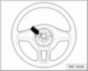
   678 Earth point in steering wheel -arrow-
 
VW FOX 2010 Earth point, in engine compartment https://portal-diagnostov.com/license.html
https://portal-diagnostov.com/license.html Automotive Electricians Portal FZCO Automotive Electricians Portal FZCO
Получить доступ ко всем электросхемам автомобиляDownload PDF file
Earth points in rear part of vehicle
VW FOX 2010 Earth point, in engine compartment https://portal-diagnostov.com/license.html
https://portal-diagnostov.com/license.html Automotive Electricians Portal FZCO Automotive Electricians Portal FZCO
Получить доступ ко всем электросхемам автомобиляDownload PDF file
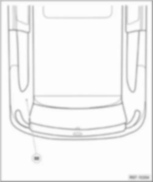
   50 Earth points, on left in luggage compartment
q   Location: → Reference

   
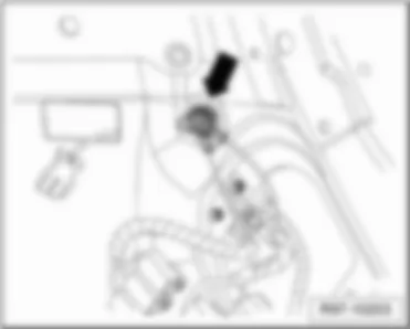
   50 Earth points, on left in luggage compartment -arrow-
 
VW FOX 2010 Earth point, in engine compartment https://portal-diagnostov.com/license.html
https://portal-diagnostov.com/license.html Automotive Electricians Portal FZCO Automotive Electricians Portal FZCO
Получить доступ ко всем электросхемам автомобиляDownload PDF file


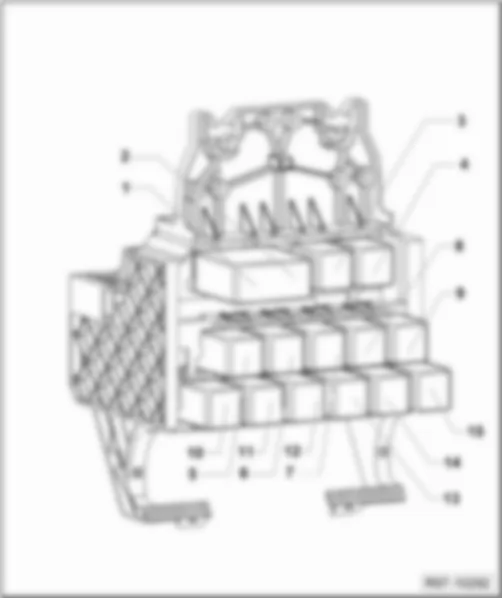
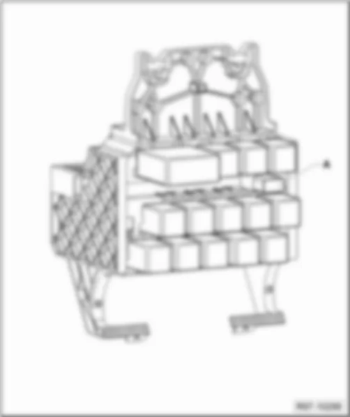
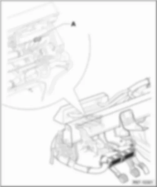
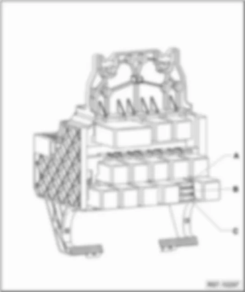
VW FOX 2010 Relay, behind left dash panel

Relay, behind left dash panel
Designation of relay: (up to April 2009 )
VW FOX 2010 Relay, behind left dash panel https://portal-diagnostov.com/license.html
https://portal-diagnostov.com/license.html Automotive Electricians Portal FZCO Automotive Electricians Portal FZCO
Получить доступ ко всем электросхемам автомобиляDownload PDF file
1 -  Mirror memory control unit -J267-
q   Colour: black
2 -  Mirror memory control unit -J267-
q   Colour: black
3 -  Fuel pump relay -J17-
q   Colour: black
4 -  Air conditioning system switch-off relay -J365-
q   Colour: black or blue
5 -  Glow plug relay -J52-
q   Colour: white
5 -  Fuel supply relay -J643-
q   Colour: grey
6 -  Dipped beam relay -J331-
q   Colour: black
7 -  Headlight main beam relay -J12-
q   Colour: black
8 -  Heated rear window control relay -J48-
q   Colour: blue
9 -  Automatic intermittent wash and wipe relay -J31-
q   Colour: red
10 -  Radiator fan 2nd speed relay -J101-
q   Colour: black
11 -  Fresh air blower and radiator fan relay -J209-
q   Colour: black
12 -  X-contact relief relay -J59-
q   Colour: grey
13 -  Dual tone horn relay -J4-
q   Colour: black
14 -  Relay for air conditioning system, diesel engine -J825-
q   Colour: black
15 -  Cold start device relay -J41-
q   Colour: black
q   for models with Total Flex engines only

   
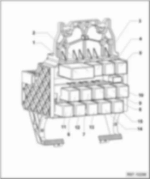
Designation of relay: (from April 2009)
VW FOX 2010 Relay, behind left dash panel https://portal-diagnostov.com/license.html
https://portal-diagnostov.com/license.html Automotive Electricians Portal FZCO Automotive Electricians Portal FZCO
Получить доступ ко всем электросхемам автомобиляDownload PDF file
1 -  Mirror memory control unit -J267-
q   Colour: dark grey
2 -  Mirror memory control unit -J267-
q   Colour: dark grey
3 -  Fuel supply relay -J643-
q   Colour: grey
3 -  Voltage supply relay 1 -J701-
q   Colour: grey
4 -  Fuel pump relay -J17-
q   Colour: black
5 -  Air conditioning system switch-off relay -J365-
q   Colour: black or blue
6 -  Radiator fan 2nd speed relay -J101-
q   Colour: black
7 -  Dipped beam relay -J331-
q   Colour: black
8 -  Headlight main beam relay -J12-
q   Colour: black
9 -  Heated rear window control relay -J48-
q   Colour: blue
10 -  Automatic intermittent wash and wipe relay -J31-
q   Colour: red
11 -  Fresh air blower and radiator fan relay -J209-
q   Colour: black
12 -  X-contact relief relay -J59-
q   Colour: grey
13 -  Dual tone horn relay -J4-
q   Colour: black
14 -  Relay for air conditioning system, diesel engine -J825-
q   Colour: black
15 -  Cold start device relay -J41-
q   Colour: black
q   for models with Total Flex engines only
15 -  Terminal 30 voltage supply relay -J317-
q   Colour: grey

   
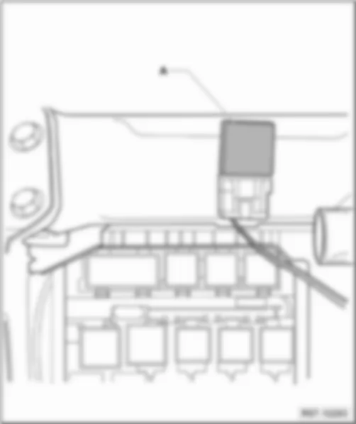
Relay above relay carrier
Designation of relay:
VW FOX 2010 Relay, behind left dash panel https://portal-diagnostov.com/license.html
https://portal-diagnostov.com/license.html Automotive Electricians Portal FZCO Automotive Electricians Portal FZCO
Получить доступ ко всем электросхемам автомобиляDownload PDF file
A -  Hazard warning light relay -J2 -
q   Colour: yellow

   
Fox Europa
VW FOX 2010 Relay, behind left dash panel https://portal-diagnostov.com/license.html
https://portal-diagnostov.com/license.html Automotive Electricians Portal FZCO Automotive Electricians Portal FZCO
Получить доступ ко всем электросхемам автомобиляDownload PDF file
1 -  Relay, behind left dash panel:
q   Designation of relay: → Reference

   
Relay, behind left dash panel
Designation of relay:
VW FOX 2010 Relay, behind left dash panel https://portal-diagnostov.com/license.html
https://portal-diagnostov.com/license.html Automotive Electricians Portal FZCO Automotive Electricians Portal FZCO
Получить доступ ко всем электросхемам автомобиляDownload PDF file
1 -  Daytime running lights relay, side and tail lights -J277-
q   Colour: black or grey
2 -  Daytime running lights relay, side and tail lights -J277-
q   Colour: black or grey
3 -  Glow plug relay -J52-
q   Colour: white
4 -  Fuel pump relay -J17-
q   Colour: grey
5 -  Headlight main beam relay -J12-
q   Colour: black
6 -  -Vazio-
q   Colour: -
7 -  Automatic gearbox relay -J60-
q   Colour: grey
8 -  Low heat output relay -J359-
q   Colour: grey
9 -  High heat output relay -J360-
q   Colour: black
10 -  Fresh air blower and radiator fan relay -J209-
q   Colour: black
11 -  X-contact relief relay -J59-
q   Colour: grey
12 -  Fuel supply relay -J643-
q   Colour: grey
13 -  Current supply relay -J16-
q   Colour: grey
13 -  Terminal 30 voltage supply relay -J317-
q   Colour: grey
13 -  Current supply relay for 4EV -J778-
q   Colour: grey
14 -  -Adaptador dos fusíveis do aquecimento-
q   Colour: black
15 -  Radiator fan 2nd speed relay -J101-
q   Colour: black


VW FOX 2010

Ground cable, battery-body- Arrow A -

VW FOX 2010 Engine compartment earth points

Engine compartment earth points
VW FOX 2010 Engine compartment earth points https://portal-diagnostov.com/license.html
https://portal-diagnostov.com/license.html Automotive Electricians Portal FZCO Automotive Electricians Portal FZCO
Получить доступ ко всем электросхемам автомобиляDownload PDF file
   1 Ground cable, battery-body
q   Fitting Location: → Reference
   2 Ground cable, gearbox-body
q   Fitting Location: → Reference
   12 Engine comp. left earth points
q   Fitting Location: → Reference
   13 Engine comp. right earth points
q   Fitting Location: . → Reference
   49 Earth points, next to the battery
q   Fitting Location: → Reference
   614 Earth point 2 in the right engine compartment
q   Fitting Location: → Reference
   671 Earth point 1 on the front left side member
q   Fitting Location: → Reference
   672 Earth point 2 on the front left side member
q   Fitting Location: → Reference

   
   1 Ground cable, battery-body- Arrow A -
   49 Earth points, next to the battery - Arrow B -
 
VW FOX 2010 Engine compartment earth points https://portal-diagnostov.com/license.html
https://portal-diagnostov.com/license.html Automotive Electricians Portal FZCO Automotive Electricians Portal FZCO
Получить доступ ко всем электросхемам автомобиляDownload PDF file
   2 Ground cable, gearbox-body- Arrow A -
   672 Earth point 2 on the front left side member - Arrow B -
 
VW FOX 2010 Engine compartment earth points https://portal-diagnostov.com/license.html
https://portal-diagnostov.com/license.html Automotive Electricians Portal FZCO Automotive Electricians Portal FZCO
Получить доступ ко всем электросхемам автомобиляDownload PDF file
   671 Earth point 1 on the front left side member - Arrow A -
 
VW FOX 2010 Engine compartment earth points https://portal-diagnostov.com/license.html
https://portal-diagnostov.com/license.html Automotive Electricians Portal FZCO Automotive Electricians Portal FZCO
Получить доступ ко всем электросхемам автомобиляDownload PDF file
   12 Earth points to the left of the engine comp.-Arrow-
 
VW FOX 2010 Engine compartment earth points https://portal-diagnostov.com/license.html
https://portal-diagnostov.com/license.html Automotive Electricians Portal FZCO Automotive Electricians Portal FZCO
Получить доступ ко всем электросхемам автомобиляDownload PDF file
   13 Earth points to the right of the engine comp.- Arrow -
 
VW FOX 2010 Engine compartment earth points https://portal-diagnostov.com/license.html
https://portal-diagnostov.com/license.html Automotive Electricians Portal FZCO Automotive Electricians Portal FZCO
Получить доступ ко всем электросхемам автомобиляDownload PDF file
   614 Earth point 2 in the right engine compartment- Arrow -
 
VW FOX 2010 Engine compartment earth points https://portal-diagnostov.com/license.html
https://portal-diagnostov.com/license.html Automotive Electricians Portal FZCO Automotive Electricians Portal FZCO
Получить доступ ко всем электросхемам автомобиляDownload PDF file
Vehicle interior earth points
VW FOX 2010 Engine compartment earth points https://portal-diagnostov.com/license.html
https://portal-diagnostov.com/license.html Automotive Electricians Portal FZCO Automotive Electricians Portal FZCO
Получить доступ ко всем электросхемам автомобиляDownload PDF file
   605 Earth point on the upper steering column region
q   Fitting Location: → Reference
   606 Earth point under the central console, next to the selector lever
q   Fitting Location: → Reference
   678 Steering wheel earth point
q   Fitting Location: → Reference

   
   605 Earth point on the upper steering column region - Arrow -
 
VW FOX 2010 Engine compartment earth points https://portal-diagnostov.com/license.html
https://portal-diagnostov.com/license.html Automotive Electricians Portal FZCO Automotive Electricians Portal FZCO
Получить доступ ко всем электросхемам автомобиляDownload PDF file
   606 Earth point under the central console, next to the selector lever- Arrows -
 
VW FOX 2010 Engine compartment earth points https://portal-diagnostov.com/license.html
https://portal-diagnostov.com/license.html Automotive Electricians Portal FZCO Automotive Electricians Portal FZCO
Получить доступ ко всем электросхемам автомобиляDownload PDF file
   678 Steering wheel earth point- Arrow -
 
VW FOX 2010 Engine compartment earth points https://portal-diagnostov.com/license.html
https://portal-diagnostov.com/license.html Automotive Electricians Portal FZCO Automotive Electricians Portal FZCO
Получить доступ ко всем электросхемам автомобиляDownload PDF file
Earth points in the rear vehicle area
VW FOX 2010 Engine compartment earth points https://portal-diagnostov.com/license.html
https://portal-diagnostov.com/license.html Automotive Electricians Portal FZCO Automotive Electricians Portal FZCO
Получить доступ ко всем электросхемам автомобиляDownload PDF file
   50 Left boot earth points
q   Fitting Location: → Reference

   
   50 Left boot earth points-Arrow -
 
VW FOX 2010 Engine compartment earth points https://portal-diagnostov.com/license.html
https://portal-diagnostov.com/license.html Automotive Electricians Portal FZCO Automotive Electricians Portal FZCO
Получить доступ ко всем электросхемам автомобиляDownload PDF file


VW FOX 2010

Window regulator single fuse -S37-

VW FOX 2010 Fuse holder battery (S)

Fuse holder battery (S)
Fuse colours:
VW FOX 2010 Fuse holder battery (S) https://portal-diagnostov.com/license.html
https://portal-diagnostov.com/license.html Automotive Electricians Portal FZCO Automotive Electricians Portal FZCO
Получить доступ ко всем электросхемам автомобиляDownload PDF file
 -  175 A - black
 -  110 A - black
 -  50 A - red / black or red / green
 -  40 A - red / black
 -  30 A - red or red / purple
 -  25 A - red / green
 -  15 A - red / yellow
 -  5 A - red / black or red / purple

Fuse holder battery (S):
t  Table 1
   
No. Current Flow Diagram designation Nominal value Function/component Terminal
1 Fuse 1 (30) in fuse holder on battery -S162- 175 A Alternator -C- 30a
Voltage regulator -C1-
2 Fuse 2 (30) in fuse holder on battery -S163- 110 A Terminal 30 wiring junction -TV2- 30a
Terminal 30a wiring junction -TV3- (up to December 2005)
X-contact relief relay -J59-
Ignition/starter switch -D- (for models with 1.9l diesel engine only)
Headlight main beam relay -J12- (for models with 1.9l diesel engine only)
Terminal 30 voltage supply relay -J317- (for models with 1.9l diesel engine only)
Dipped beam relay -J331- (for models with 1.9l diesel engine only)
Fuse 8 on fuse holder C -SC8- (for models with 1.9l diesel engine only)
Fuse 25 on fuse holder B -SB25- (for models with 1.9l diesel engine only)
Fuse 27 on fuse holder B -SB27- (for models with 1.9l diesel engine only)
Fuse 28 on fuse holder B -SB28- (for models with 1.9l diesel engine only)
Fuse 39 on fuse holder B -SB39- (for models with 1.9l diesel engine only)
3 Fuse 3 (30) in fuse holder on battery -S164- 40 A Radiator fan 2nd speed relay -J101- 30a
Radiator fan control unit -J293- (for models with 1.9l diesel engine only)
50 A Radiator fan 2nd speed relay -J101-
4 Fuse 4 (30) in fuse holder on battery -S176- 40 A ABS control unit -J104- (for models with 1.9l diesel engine only) 30a
50 A ABS control unit -J104-
5 Fuse 5 (30) in fuse holder on battery -S177- 40 A ABS control unit -J104- 30a
50 A Steering hydraulics pump -V119- (for models with 1.9l diesel engine only)
6 Fuse 6 (30) in fuse holder on battery -S178- 50 A Glow plug relay -J52- (for models with 1.9l diesel engine only) 30a
7 Fuse 7 (30) in fuse holder on battery -S179- 25 A ABS control unit -J104- 30a
8 Fuse 8 (30) in fuse holder on battery -S180- 30 A Radiator fan 2nd speed relay -J101- 30a
Fresh air blower and radiator fan relay -J209-
Radiator fan control unit -J293-
9 Fuse 9 (30) in fuse holder on battery -S267- 5 A Radiator fan control unit -J293- (for models with 1.9l diesel engine only) 30a
 
10 Fuse 10 (30) in fuse holder on battery -S268- 15 A Motronic control unit -J220- (up to December 2005) 30a
Engine control unit -J623-
4MV injection system control unit control unit -J776- (up to April 2007)
11 Fuse 11 (30) in fuse holder on battery -S269- 5 A Onboard supply control unit -J519- (for models with 1.9l diesel engine only) 30a

   
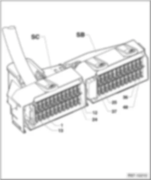
Fuse holder SB and SC
Fuse colours:
VW FOX 2010 Fuse holder battery (S) https://portal-diagnostov.com/license.html
https://portal-diagnostov.com/license.html Automotive Electricians Portal FZCO Automotive Electricians Portal FZCO
Получить доступ ко всем электросхемам автомобиляDownload PDF file
 -  25 A - white
 -  20 A - yellow
 -  15 A - blue
 -  10 A - red
 -  5 A - beige

Fuse holder (SC)
t  Table 2
   
No. Current Flow Diagram designation Nominal value Function/component Terminal
1 Fuse 1 on fuse holder C -SC1- 5 A Radiator fan control unit -J293- (for models with 1.9l diesel engine only) 15a
High pressure sender -G65-
2 Fuse 2 on fuse holder C -SC2- 5 A Convenience system central control unit -J393- 86s
Onboard supply control unit -J519-
Radio -R-
3 Fuse 3 on fuse holder C -SC3- 5 A Power steering control unit -J500- 15a
4 Fuse 4 on fuse holder C -SC4- 5 A Rear lid release switch -E165- (up to April 2007) 30a
Driver door exterior handle switch for anti-theft alarm system -F121-
5 Fuse 5 on fuse holder C -SC5- 20 A Radio -R- 30a
6 Fuse 6 on fuse holder C -SC6- 20 A Heated rear window control relay -J48- XR
Onboard supply control unit -J519- (for models with 1.9l diesel engine only)
7 Fuse 7 on fuse holder C -SC7- - Vacant -
8 Fuse 8 on fuse holder C -SC8- 5 A Onboard supply control unit -J519- (for models with 1.9l diesel engine only) 30a
9 Fuse 9 on fuse holder C -SC9- - Vacant -
10 Fuse 10 on fuse holder C -SC10- 5 A Cold start device relay -J41- (only models with Total Flex) 30a
11 Fuse 11 on fuse holder C -SC11- 10 A Light switch -E1- R
Front right turn signal bulb -M7-
Rear right turn signal bulb -M8-
Hazard warning light switch -E3-
Dash panel insert -K-
Hazard warning light system warning lamp -K6-
Control unit with display in dash panel insert -J285-
Onboard supply control unit -J519- (for models with 1.9l diesel engine only)
12 Fuse 12 on fuse holder C -SC12- 10 A Light switch -E1- L
Front left turn signal bulb -M5-
Rear left turn signal bulb -M6-
Hazard warning light switch -E3-
Dash panel insert -K-
Hazard warning light system warning lamp -K6-
Control unit with display in dash panel insert -J285-
Onboard supply control unit -J519- (for models with 1.9l diesel engine only)
13 Fuse 13 on fuse holder C -SC13- - Vacant -
14 Fuse 14 on fuse holder C -SC14- 5 A Mirror adjustment switch -E43- 15a
Mirror adjustment change-over switch -E48-
Rear lid release switch -E165- (up to April 2007)
Mirror memory control unit -J267-
Convenience system central control unit -J393-
Mirror adjustment switch illumination bulb -L78-
15 Fuse 15 on fuse holder C -SC15- 25 A Air conditioning system switch-off relay -J365- 30a
16 Fuse 16 on fuse holder C -SC16- 25 A Convenience system central control unit -J393- 30a
17 Fuse 17 on fuse holder C -SC17- 15 A Front and rear fog light switch -E23- 55
Front and rear fog light switch illumination bulb -L40-
18 Fuse 18 on fuse holder C -SC18- 10 A Rear window wiper motor -V12- XR
19 Fuse 19 on fuse holder C -SC19- - Vacant -
20 Fuse 20 on fuse holder C -SC20- - Vacant -
21 Fuse 21 on fuse holder C -SC21- - Vacant -
22 Fuse 22 on fuse holder C -SC22- - Vacant -
23 Fuse 23 on fuse holder C -SC23- 5 A ABS control unit -J104- 15a
ABS return flow pump relay -J105-
ABS solenoid valve relay -J106-
Front right ABS inlet valve -N99-
Front right ABS outlet valve -N100-
Front left ABS inlet valve -N101-
Front left ABS outlet valve -N102-
ABS return flow pump -V39-
24 Fuse 24 on fuse holder C -SC24- 10 A ABS control unit -J104- (for models with 1.9l diesel engine only) 30a
ABS return flow pump relay -J105- (for models with 1.9l diesel engine only)
ABS solenoid valve relay -J106- (for models with 1.9l diesel engine only)
Front right ABS inlet valve -N99- (for models with 1.9l diesel engine only)
Front right ABS outlet valve -N100- (for models with 1.9l diesel engine only)
Front left ABS inlet valve -N101- (for models with 1.9l diesel engine only)
Front left ABS outlet valve -N102- (for models with 1.9l diesel engine only)
ABS return flow pump -V39- (for models with 1.9l diesel engine only)

Fuse holder (SB)
t  Table 3
   
No. Current Flow Diagram designation Nominal value Function/component Terminal
25 Fuse 25 on fuse holder B -SB25- 10 A Airbag coil connector and return spring with slip ring -F138- 15a
Onboard supply control unit -J519- (for models with 1.9l diesel engine only)
26 Fuse 26 on fuse holder B -SB26- 10 A Ignition transformer -N152- 15a
25 A Fuel supply relay -J643- (for models with engine code BLH only)
27 Fuse 27 on fuse holder B -SB27- 10 A 16-pin connector -T16a- (for models with 1.9l diesel engine only) 30a
15 A 16-pin connector -T16a-
Hazard warning light switch -E3-
Hazard warning light system warning lamp -K6-
Radiator fan 2nd speed relay -J101-
Fresh air blower and radiator fan relay -J209-
28 Fuse 28 on fuse holder B -SB28- 5 A Dash panel insert -K- 30a
Control unit with display in dash panel insert -J285-
Air conditioning system control unit -J301-
29 Fuse 29 on fuse holder B -SB29- 15 A Intermittent wiper switch -E22- 53a
Automatic intermittent wash and wipe relay -J31-
Windscreen wiper motor -V-
30 Fuse 30 on fuse holder B -SB30- 5 A Engine control unit -J623- 15a
31 Fuse 31 on fuse holder B -SB31- 5 A Right tail light bulb -M2- 58r
Right side light bulb -M3-
32 Fuse 32 on fuse holder B -SB32- 5 A Cigarette lighter illumination bulb -L28- 58
Socket illumination bulb -L42-
Hazard warning light switch -E3-
Dash panel insert -K-
Hazard warning light system warning lamp -K6-
Number plate light -X-
Control unit with display in dash panel insert -J285-
33 Fuse 33 on fuse holder B -SB33- 15 A Fuel gauge sender -G- 87a
Fuel system pressurisation pump -G6-
34 Fuse 34 on fuse holder B -SB34- 10 A Activated charcoal filter system solenoid valve 1 -N80- 87a
35 Fuse 35 on fuse holder B -SB35- 10 A Dash panel insert -K- 56al
Control unit with display in dash panel insert -J285-
Left main beam bulb -M30-
15 A Dash panel insert -K-
Control unit with display in dash panel insert -J285-
Left main beam bulb -M30-
Left additional main bean bulb -M67- (for Cross only)
36 Fuse 36 on fuse holder B -SB36- 10 A Left headlight twin filament bulb/left sealed beam insert -L1- 56bl
Left dipped beam bulb -M29-
37 Fuse 37 on fuse holder B -SB37- 10 A Reversing light switch -F4- 15a
38 Fuse 38 on fuse holder B -SB38- 5 A Clutch pedal switch -F36- 15a
Brake pedal switch -F47-
Fuel pump relay -J17-
Cold start device relay -J41-
Control unit with display in dash panel insert -J285-
Immobilizer control unit -J362-
Air conditioning system switch-off relay -J365-
Dash panel insert -K-
Anti-dazzle interior mirror warming lamp -K187-
Spare wheel release warning light -K246-
Anti-dazzle interior mirror button -E386-
Speedometer sender -G22-
Automatic anti-dazzle interior mirror -Y7-
39 Fuse 39 on fuse holder B -SB39- 10 A Front interior light -W1- 30a
Luggage compartment light -W3-
Front passenger side reading light -W13-
Front passenger side illuminated vanity mirror -W14-
Driver side reading light -W19-
Driver side illuminated vanity mirror -W20-
Mirror memory control unit -J267-
Onboard supply control unit -J519- (for models with 1.9l diesel engine only)
40 Fuse 40 on fuse holder B -SB40- 10 A Brake light switch -F- 15a
41 Fuse 41 on fuse holder B -SB41- 10 A Dual tone horn relay -J4- 15a
Horn or dual tone horn -H1-
Onboard supply control unit -J519- (for models with 1.9l diesel engine only)
42 Fuse 42 on fuse holder B -SB42- 25 A High pressure sender -G65- (up to August 2008) XR
Fresh air blower switch -E9-
Fresh air/recirculated air flap control motor -V154-
Air conditioning system control unit -J301-
43 Fuse 43 on fuse holder B -SB43- 5 A Left side light bulb -M1- 58l
Left tail light bulb -M4-
Left brake and tail light bulb -M21-
44 Fuse 44 on fuse holder B -SB44- 5 A Clutch pedal switch -F36- (for models with 1.9l diesel engine only) 87a
Brake pedal switch -F47- (for models with 1.9l diesel engine only)
Glow plug relay -J52- (for models with 1.9l diesel engine only)
10 A Injector, cylinder 1 -N30-
Injector, cylinder 2 -N31-
Injector, cylinder 3 -N32-
Injector, cylinder 4 -N33-
45 Fuse 45 on fuse holder B -SB45- 10 A Lambda probe -G39- 87a
Lambda probe after catalytic converter -G130-
30 A Metering adjuster (diesel injection) -N146- (for models with 1.9l diesel engine only)
Engine control unit -J623- (for models with 1.9l diesel engine only)
46 Fuse 46 on fuse holder B -SB46- 10 A Right headlight twin filament bulb/right sealed beam insert -L2- 56a
Right main beam bulb -M32-
15 A Right headlight twin filament bulb/right sealed beam insert -L2- 56ar
Right main beam bulb -M32-
Right additional main bean bulb -M68- (for Cross only)
47 Fuse 47 on fuse holder B -SB47- 10 A Right headlight twin filament bulb/right sealed beam insert -L2- 56br
Right dipped beam bulb -M31-
48 Fuse 48 on fuse holder B -SB48- 20 A Cigarette lighter -U1- XR
12 V socket -U5-

   
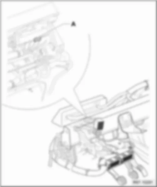
Window regulator single fuse, on relay carrier
Window regulator single fuse -S37- (up to April 2009)
VW FOX 2010 Fuse holder battery (S) https://portal-diagnostov.com/license.html
https://portal-diagnostov.com/license.html Automotive Electricians Portal FZCO Automotive Electricians Portal FZCO
Получить доступ ко всем электросхемам автомобиляDownload PDF file
A -  Window regulator single fuse -S37-
q   Colour: yellow
q   Fitting Locations: behind the relay carrier

   
Window regulator single fuse -S37- (from April 2009)
VW FOX 2010 Fuse holder battery (S) https://portal-diagnostov.com/license.html
https://portal-diagnostov.com/license.html Automotive Electricians Portal FZCO Automotive Electricians Portal FZCO
Получить доступ ко всем электросхемам автомобиляDownload PDF file
A -  Window regulator single fuse -S37-
q   Colour: yellow
q   Fitting Locations: on front relay carrier

   
Fox Europa
VW FOX 2010 Fuse holder battery (S) https://portal-diagnostov.com/license.html
https://portal-diagnostov.com/license.html Automotive Electricians Portal FZCO Automotive Electricians Portal FZCO
Получить доступ ко всем электросхемам автомобиляDownload PDF file
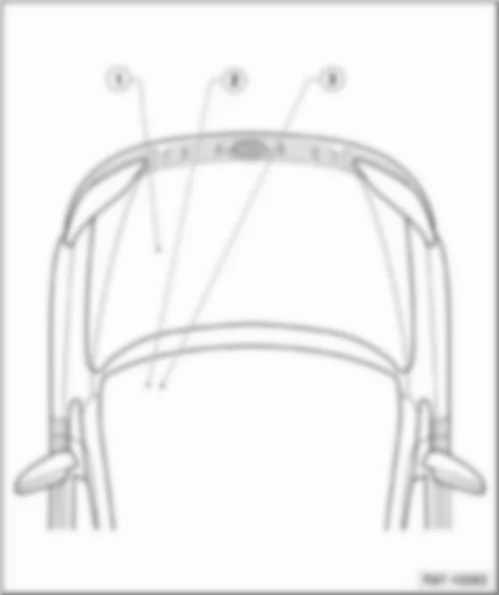
1 -  Fuse holder battery (S)
q   Fuse colours: → Reference
q   Fuse holder battery (S): → Reference
2 -  Fuse holder SB and SC
q   Fuse colours: → Reference
q   Fuse holder (SC): → Reference
q   Fuse holder (SB): → Reference
3 -  Fuses on relay carrier
q   Window regulator single fuse -S37- → Reference
q   Heater element fuses: → Reference

   
Fuse holder battery (S)
Fuse colours:
VW FOX 2010 Fuse holder battery (S) https://portal-diagnostov.com/license.html
https://portal-diagnostov.com/license.html Automotive Electricians Portal FZCO Automotive Electricians Portal FZCO
Получить доступ ко всем электросхемам автомобиляDownload PDF file
 -  175 A - black
 -  110 A - black
 -  50 A - red / black or red / green
 -  40 A - red / black
 -  30 A - red or red / purple
 -  25 A - red / green
 -  15 A - red / yellow
 -  5 A - red / black or red / purple

Fuse holder battery (S):
t  Table 1
   
No. Current Flow Diagram designation Nominal value Function/component Terminal
1 Fuse 1 (30) in fuse holder on battery -S162- 175 A Alternator -C- 30a
Voltage regulator -C1-
2 Fuse 2 (30) in fuse holder on battery -S163- 110 A Terminal 30 wiring junction -TV2- 30a
3 Fuse 3 (30) in fuse holder on battery -S164- 40 A Radiator fan control unit -J293- 30a
4 Fuse 4 (30) in fuse holder on battery -S176- 50 A Glow plug relay -J52- (for models with 1.4 l diesel engine only) 30a
5 Fuse 5 (30) in fuse holder on battery -S177- 40 A Steering hydraulics pump -V119- 30a
ABS control unit -J104-
Radiator fan control unit -J293-
Power steering control unit -J500-
50 A Steering hydraulics pump -V119- (up to December 2006)
Power steering control unit -J500- (up to December 2006)
6 Fuse 6 (30) in fuse holder on battery -S178- - Vacant -
7 Fuse 7 (30) in fuse holder on battery -S179- 25 A ABS control unit -J104- 30a
8 Fuse 8 (30) in fuse holder on battery -S180- 30 A Radiator fan thermal switch -F18- (for models with 1.2 l and 1.4 l diesel engine only) 30a
Radiator fan 2nd speed relay -J101- (for models with 1,4l engine only)
Fresh air blower and radiator fan relay -J209- (for models with 1,4l engine only)
Radiator fan control unit -J293-
9 Fuse 9 (30) in fuse holder on battery -S267- 5 A Radiator fan control unit -J293- 30a
 
10 Fuse 10 (30) in fuse holder on battery -S268- 15 A Onboard supply control unit -J519- (up to December 2006) 30a
Engine control unit -J623-
11 Fuse 11 (30) in fuse holder on battery -S269- 5 A Air conditioning system control unit -J301- 30a
Radiator fan control unit -J293-

   
Fuse holder SB and SC
Fuse colours:
VW FOX 2010 Fuse holder battery (S) https://portal-diagnostov.com/license.html
https://portal-diagnostov.com/license.html Automotive Electricians Portal FZCO Automotive Electricians Portal FZCO
Получить доступ ко всем электросхемам автомобиляDownload PDF file
 -  25 A - white
 -  20 A - yellow
 -  15 A - blue
 -  10 A - red
 -  5 A - beige

Fuse holder (SC)
t  Table 2
   
No. Current Flow Diagram designation Nominal value Function/component Terminal
1 Fuse 1 on fuse holder C -SC1- 5 A High pressure sender -G65- 15a
Radiator fan control unit -J293-
Air conditioning system control unit -J301-
2 Fuse 2 on fuse holder C -SC2- 5 A Convenience system central control unit -J393- 86s
Onboard supply control unit -J519-
3 Fuse 3 on fuse holder C -SC3- 5 A Speedometer sender -G22- 15a
Power steering control unit -J500-
Spray jet heater element for windscreen washer system -N113-
4 Fuse 4 on fuse holder C -SC4- 5 A Driver door exterior handle switch for anti-theft alarm system -F121- 30a
5 Fuse 5 on fuse holder C -SC5- 20 A Radio -R- 30a
6 Fuse 6 on fuse holder C -SC6- 20 A Heated rear window control relay -J48- 30a
Onboard supply control unit -J519-
7 Fuse 7 on fuse holder C -SC7- 10 A Intermittent wiper switch -E22- XRA
8 Fuse 8 on fuse holder C -SC8- 5 A Onboard supply control unit -J519- 30a
9 Fuse 9 on fuse holder C -SC9- - Vacant -
10 Fuse 10 on fuse holder C -SC10- 20 A Sliding sunroof adjustment control unit -J245- 30a
11 Fuse 11 on fuse holder C -SC11- 10 A Front right turn signal bulb -M7- RA
Rear right turn signal bulb -M8-
Right side mounted turn signal bulb -M19-
Convenience system central control unit -J393-
Onboard supply control unit -J519-
12 Fuse 12 on fuse holder C -SC12- 10 A Front left turn signal bulb -M5- LA
Rear left turn signal bulb -M6-
Left side mounted turn signal bulb -M18-
Convenience system central control unit -J393-
Onboard supply control unit -J519-
13 Fuse 13 on fuse holder C -SC13- - Vacant -
14 Fuse 14 on fuse holder C -SC14- 5 A Mirror adjustment switch -E43- 15a
Convenience system central control unit -J393-
15 Fuse 15 on fuse holder C -SC15- 15 A Heated driver seat regulator -E94- XR
Heated front passenger seat regulator -E95-
Heated driver seat control unit -J131-
16 Fuse 16 on fuse holder C -SC16- 25 A Convenience system central control unit -J393- 30a
17 Fuse 17 on fuse holder C -SC17- 15 A Front and rear fog light switch -E23- XR
Front and rear fog light switch illumination bulb -L40-
18 Fuse 18 on fuse holder C -SC18- 10 A Rear window wiper motor -V12- XR
19 Fuse 19 on fuse holder C -SC19- - Vacant -
20 Fuse 20 on fuse holder C -SC20- 5 A Driver side heated exterior mirror -Z4- 30a
Front passenger side heated exterior mirror -Z5-
Onboard supply control unit -J519-
21 Fuse 21 on fuse holder C -SC21- - Vacant -
22 Fuse 22 on fuse holder C -SC22- - Vacant -
23 Fuse 23 on fuse holder C -SC23- 5 A Steering angle sender -G85- 15a
TCS and ESP button -E256-
Switches and instruments regulator illumination bulb -L155-
ABS control unit -J104-
24 Fuse 24 on fuse holder C -SC24- 10 A Steering angle sender -G85- 30a
ABS control unit -J104-

Fuse holder (SB)
t  Table 3
   
No. Current Flow Diagram designation Nominal value Function/component Terminal
25 Fuse 25 on fuse holder B -SB25- 10 A Front left turn signal bulb -M5- 30a
Rear left turn signal bulb -M6-
Front right turn signal bulb -M7-
Rear right turn signal bulb -M8-
Onboard supply control unit -J519-
26 Fuse 26 on fuse holder B -SB26- 10 A Ignition coil 1 with output stage -N70- 87a
Ignition coil 2 with output stage -N127-
Ignition coil 3 with output stage -N291-
Ignition transformer -N152- (for models with 1,4l engine only)
Engine control unit -J623-
27 Fuse 27 on fuse holder B -SB27- 15 A Air conditioning system control unit -J301- 30a
16-pin connector, diagnostic -T16a-
28 Fuse 28 on fuse holder B -SB28- 5 A Dash panel insert -K- 30a
Convenience system central control unit -J393-
29 Fuse 29 on fuse holder B -SB29- 20 A Automatic intermittent wash and wipe relay -J31- 53a
Onboard supply control unit -J519-
30 Fuse 30 on fuse holder B -SB30- 5 A Heater element for crankcase breather -N79- (for models with 1.4 l petrol engine) 15a
Air mass meter -G70- (for models with 1.4 l diesel engine only)
Current supply relay -J16- (for models with 1.2 l engine only)
Engine control unit -J623-
31 Fuse 31 on fuse holder B -SB31- 5 A Right tail light bulb -M2- (up to December 2006) 58r
Right side light bulb -M3-
Right brake and tail light bulb -M22-
Dash panel insert -K-
32 Fuse 32 on fuse holder B -SB32- 5 A Number plate light -X- 58
33 Fuse 33 on fuse holder B -SB33- 15 A Fuel gauge sender -G- 87a
Fuel system pressurisation pump -G6-
34 Fuse 34 on fuse holder B -SB34- 10 A Hall sender -G40- (for models with 1.2 l and 1.4 l petrol engines only) 87a
Intake manifold flap motor -V157- (for models with 1.4 l diesel engine only)
Exhaust gas recirculation valve -N18- (for models with 1.4 l diesel engine only)
Charge pressure control solenoid valve -N75- (for models with 1.4 l diesel engine only)
Activated charcoal filter system solenoid valve 1 -N80- (for models with 1.2 l and 1.4 l petrol engines only)
35 Fuse 35 on fuse holder B -SB35- 10 A Front and rear fog light switch -E23- 56al
Front and rear fog light switch illumination bulb -L40-
Left headlight twin filament bulb/left sealed beam insert -L1-
Dash panel insert -K-
Left main beam bulb -M30- (up to November 2006)
36 Fuse 36 on fuse holder B -SB36- 10 A Front and rear fog light switch -E23- 56bl
Front and rear fog light switch illumination bulb -L40-
Left headlight twin filament bulb/left sealed beam insert -L1-
Headlight range control regulator -E102-
Left headlight range control motor -V48-
Left dipped beam bulb -M29- (up to November 2006)
37 Fuse 37 on fuse holder B -SB37- 10 A Reversing light switch -F4- 15a
Left reversing light bulb -M16-
Right reversing light bulb -M17-
Onboard supply control unit -J519-
38 Fuse 38 on fuse holder B -SB38- 5 A Clutch pedal switch -F36- 15a
Brake pedal switch -F47-
Fuel pump relay -J17-
Dash panel insert -K-
39 Fuse 39 on fuse holder B -SB39- 10 A Luggage compartment light -W3- 30a
Onboard supply control unit -J519-
40 Fuse 40 on fuse holder B -SB40- 10 A Brake light switch -F- 15a
41 Fuse 41 on fuse holder B -SB41- 10 A Horn or dual tone horn -H1- 30a
Onboard supply control unit -J519-
42 Fuse 42 on fuse holder B -SB42- 25 A Fresh air blower switch -E9- XR
43 Fuse 43 on fuse holder B -SB43- 5 A Left side light bulb -M1- 58l
Left tail light bulb -M4- (up to December 2006)
Left brake and tail light bulb -M21-
Dash panel insert -K-
44 Fuse 44 on fuse holder B -SB44- 10 A Injector, cylinder 1 -N30- 87a
Injector, cylinder 2 -N31-
Injector, cylinder 3 -N32-
Injector, cylinder 4 -N33- (for models with 1.4 l petrol engine)
Engine control unit -J623-
45 Fuse 45 on fuse holder B -SB45- 10 A Lambda probe -G39- 87a
Lambda probe after catalytic converter -G130-
5 A Clutch pedal switch -F36-
Brake pedal switch -F47-
Low heat output relay -J359-
High heat output relay -J360-
46 Fuse 46 on fuse holder B -SB46- 10 A Right headlight twin filament bulb/right sealed beam insert -L2- 56ar
Right main beam bulb -M32- (up to November 2006)
47 Fuse 47 on fuse holder B -SB47- 10 A Right headlight twin filament bulb/right sealed beam insert -L2- 56br
Right dipped beam bulb -M31- (up to November 2006)
Right headlight range control motor -V49-
48 Fuse 48 on fuse holder B -SB48- 20 A Cigarette lighter -U1- XR
Cigarette lighter illumination bulb -L28-

   
Fuses on relay carrier
Window regulator single fuse - S37
VW FOX 2010 Fuse holder battery (S) https://portal-diagnostov.com/license.html
https://portal-diagnostov.com/license.html Automotive Electricians Portal FZCO Automotive Electricians Portal FZCO
Получить доступ ко всем электросхемам автомобиляDownload PDF file
A -  Window regulator single fuse -S37 - 20A-
q   Colour: yellow
q   Fitting Locations: behind the relay carrier

   
Heater element fuses
VW FOX 2010 Fuse holder battery (S) https://portal-diagnostov.com/license.html
https://portal-diagnostov.com/license.html Automotive Electricians Portal FZCO Automotive Electricians Portal FZCO
Получить доступ ко всем электросхемам автомобиляDownload PDF file
A -  Heater element fuse 1 -S276 - 40A-
q   Colour: orange
B -  Heater element fuse 2 -S277 - 40A-
q   Colour: orange
C -  Heater element fuse 3 -S278 - 40A-
q   Colour: orange