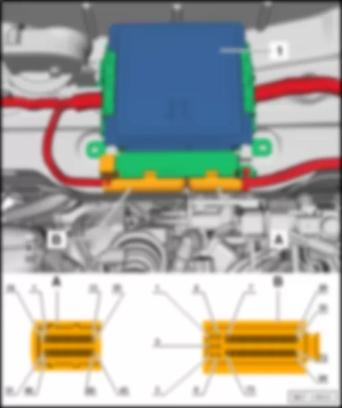
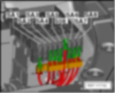
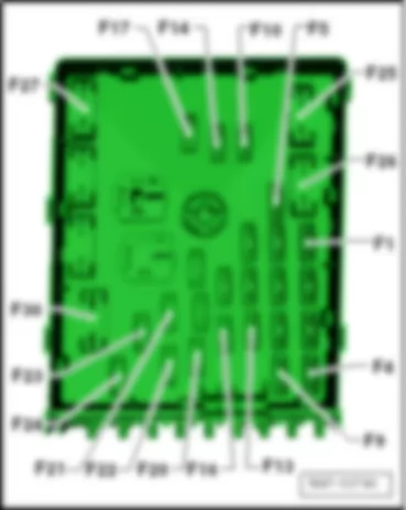
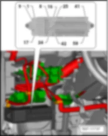
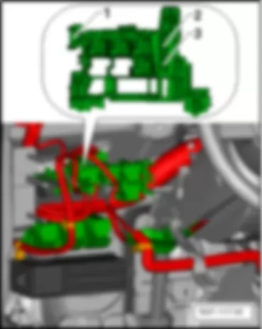
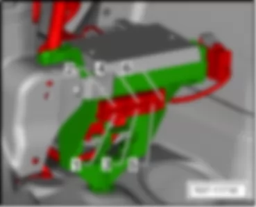
| No. | | Current Flow Diagram designation | Nominal value | | Function/component | Terminal |
| F1 | - | Fuse 1 on fuse holder B -SB1- | 30A | | Voltage stabiliser -J532- | 30 |
| F2 | - | Fuse 2 on fuse holder B -SB2- | 30A | | Onboard supply control unit -J519- , (T52b/42) | 30 |
| | | | | | # terminal 30 power | |
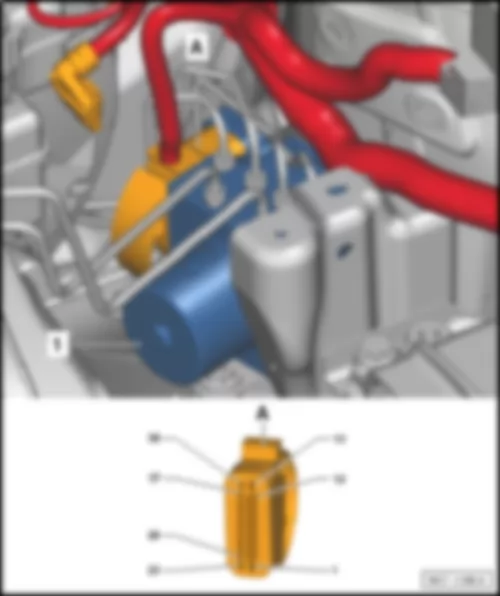
| F3 | - | Fuse 3 on fuse holder B -SB3- | 30A | | ABS control unit -J104- | 30 |
| F4 | - | Fuse 4 on fuse holder B -SB4- | 30A | | Onboard supply control unit -J519- (T52a/1) | 30 |
| | | | | | # terminal 30, left light supply | |
| F5 | - | Fuse 5 on fuse holder B -SB5- | 5A | | Onboard supply control unit -J519- , (T52a/24) | 30 |
| | | | | | # terminal 30, reference | |
| | | | | | Battery monitor control unit -J367- | 30 |
| F6 | - | Fuse 6 on fuse holder B -SB6- | 30A | | Onboard supply control unit -J519- (T52c/42) | 30 |
| | | | | | # terminal 30, right light supply | |
| F7 | - | Fuse 7 on fuse holder B -SB7- | 25A | | Dual tone horn relay -J4- | 30 |
| | | | | | Heated windscreen relay -J47- | 30 |
| F8 | - | Fuse 8 on fuse holder B -SB8- | 30 A | | Digital sound package amplifier -R184- | 30 |
| F9 | - | Fuse 9 on fuse holder B -S9- | 20A | | Control unit with display for radio and navigation -J503-4 | 30 |
| F10 | - | Fuse 10 on fuse holder B -SB10- | 30A | | Engine control unit -J623- | 87 |
| F11 | - | Fuse 11 on fuse holder B -SB11- | 5A | | Data bus diagnostic interface -J533- | 30 |
| F12 | - | Fuse 12 on fuse holder B -SB12- | 15A | | Mechatronic unit for dual clutch gearbox -J743- | 30 |
| F13 | - | Fuse 13 on fuse holder -SB13- | 5A | | Engine control unit -J623- | 30 |
| | | | | | Main relay -J271- | 30 |
| | | | | | Fuse 14 on fuse holder B -SB14- | 87 |
| | | | | | Fuse 16 on fuse holder B -SB16- | 87 |
| | | | | | Fuse 18 on fuse holder B -SB18- | 87 |
| | | | | | Fuse 20 on fuse holder B -SB20- | 87 |
| | | | | | Fuse 23 on fuse holder B -SB23- | 87 |
| | | | | | Fuse 24 on fuse holder B -SB24- | 87 |
| F14 | - | Fuse 14 on fuse holder B -SB14- | 10A | | Reducing agent pump -V437-1 | 87 |
| | | | 30A | | Ignition coil 1 with output stage -N70- | 87 |
| | | | | | Ignition coil 2 with output stage -N127- | 87 |
| | | | | | Ignition coil 3 with output stage -N291- | 87 |
| | | | | | Ignition coil 4 with output stage -N292- | 87 |
| F15 | - | Fuse 15 on fuse holder B -SB15- | - | | Vacant | 30 |
| F16 | - | Fuse 16 on fuse holder B -SB16- | 30A | | Reducing-agent heater control unit -J891-1 | 87 |
| | | | 15A | | Lambda probe -G39- | 87 |
| | | | | | Lambda probe after catalytic converter -G130- | 87 |
| | | | | | Magnetic clutch for supercharger -N421- | 87 |
| F17 | - | Fuse 17 on fuse holder B -SB17- | 20A | | Fuel pressure regulating valve -N276- | 87 |
| F18 | - | Fuse 18 on fuse holder B -SB18- | 30A | | Fuel pump control unit -J538- | 87 |
| F19 | - | Fuse 19 on fuse holder B -SB19- | 30 A | | Wiper motor control unit -J400- | 87 |
| F20 | - | Fuse 20 on fuse holder B -SB20- | 15A | | Additional coolant pump relay -J496-2 | 87 |
| | | | | | Lambda probe -G39-1 | 87 |
| | | | | | NOx sender control unit -J583-1 | 87 |
| | | | | | Air mass meter -G70-1 | 87 |
| F21 | - | Fuse 21 on fuse holder B -SB21- | 20 A | | Auxiliary heater control unit -J364- | 30 |
| F22 | - | Fuse 22 on fuse holder B -SB22- | 30A | | Rear air recirculation blower -V242-5 | 30 |
| F23 | - | Fuse 23 on fuse holder B -SB23- | 15 A | | Charge pressure control solenoid valve -N75-1 | 87 |
| | | | | | Crankcase breather heater element -N79-1 | 87 |
| | | | | | Automatic glow period control unit -J179-1 | 87 |
| | | | | | Exhaust gas recirculation cooler changeover valve -N345-1 | 87 |
| | | | | | Fuel metering valve -N290-1 | 87 |
| | | | | | Fuel pressure regulating valve -N276-1 | 87 |
| | | | | | Coolant circulation pump 2 -V178-1 | 87 |
| | | | | | Additional coolant pump relay -J496-2 | 87 |
| | | | | | Clutch position sender -G476- | 87 |
| F24 | - | Fuse 24 on fuse holder B -SB24- | 10A | | Engine component current supply relay -J757-2 , 3 | 87 |
| | | | | | #Fuse 17 on fuse holder B -SB17-2 | |
| | | | | | #Fuse 28 on fuse holder B -SB28-1 | |
| | | | | | Radiator fan control unit -J293- | 87 |
| | | | | | Turbocharger air recirculation valve -N249- | 87 |
| | | | | | Activated charcoal filter system solenoid valve 1 -N80- | 87 |
| | | | | | Camshaft control valve 1 -N205- | 87 |
| | | | | | Charge pressure control solenoid valve -N75-2 | 87 |
| | | | | | Low heat output relay -J359- | 87 |
| | | | | | High heat output relay -J360- | 87 |
| F25 | - | Fuse 25 fuse holder B -SB25- | 40A | | ABS control unit -J104- | 30 |
| F26 | - | Fuse 26 on fuse holder B -SB26- | 40A | | Fresh air blower control unit -J126- | 30 |
| | | | | | Low heat output relay -J359- | 30 |
| F27 | - | Fuse 27 on fuse holder B -SB27- | 50A | | Terminal 15 voltage supply relay 2 -J681- | 30 |
| F28 | - | Fuse 28 on fuse holder B -SB28- | 50 A | | Automatic glow period control unit -J179- | 30, (87) |
| F29 | - | Fuse 29 on fuse holder B -SB29- | 40A | | Fuse 17 on fuse holder C -SC17- | 30 |
| | | | | | Fuse 18 on fuse holder C -SC18- | 30 |
| | | | | | Fuse 36 on fuse holder C -SC36- | 30 |
| | | | | | Fuse 37 on fuse holder C -SC37- | 30 |
| | | | | | Fuse 38 on fuse holder C -SC38- | 30 |
| | | | | | Fuse 39 on fuse holder C -SC39- | 30 |
| | | | | | Fuse 40 on fuse holder C -SC40- | 30 |
| | | | | | Fuse 41 on fuse holder C -SC41- | 30 |
| | | | | | Fuse 58 on fuse holder C -SC58- | 30 |
| F30 | - | Fuse 30 on fuse holder B -SB30- | 50A | | Terminal 75 voltage supply relay 1 -J680- | 30 |
| 1 Diesel |
| 2 Petrol |
| 3 Bridge only with Diesel, else relay J757 |
| 4 Only models with no start/stop system |
| 5 See fuse assignment (SC), from May 2011 |
| No. | | Current Flow Diagram designation | Nominal value | | Function/component | Terminal |
| F1 | - | Fuse 1 on fuse holder B -SB1- | 30A | | Voltage stabiliser -J532- | 30 |
| F2 | - | Fuse 2 on fuse holder B -SB2- | 30A | | Onboard supply control unit -J519- , (T52b/42) | 30 |
| | | | | | # terminal 30 power | |
| F3 | - | Fuse 3 on fuse holder B -SB3- | 30A | | ABS control unit -J104- | 30 |
| F4 | - | Fuse 4 on fuse holder B -SB4- | 30A | | Onboard supply control unit -J519- (T52a/1) | 30 |
| | | | | | # terminal 30, left light supply | |
| F5 | - | Fuse 5 on fuse holder B -SB5- | 5A | | Onboard supply control unit -J519- , (T52a/24) | 30 |
| | | | | | # terminal 30, reference | |
| | | | | | Battery monitor control unit -J367- | 30 |
| F6 | - | Fuse 6 on fuse holder B -SB6- | 30A | | Onboard supply control unit -J519- (T52c/42) | 30 |
| | | | | | # terminal 30, right light supply | |
| F7 | - | Fuse 7 on fuse holder B -SB7- | 25A | | Dual tone horn relay -J4- | 30 |
| | | | | | Heated windscreen relay -J47- | 30 |
| F8 | - | Fuse 8 on fuse holder B -SB8- | 30 A | | Digital sound package amplifier -R184- | 30 |
| F9 | - | Fuse 9 on fuse holder B -S9- | 20A | | Control unit with display for radio and navigation -J503-4 | 30 |
| F10 | - | Fuse 10 on fuse holder B -SB10- | 30A | | Engine control unit -J623- | 87 |
| F11 | - | Fuse 11 on fuse holder B -SB11- | 5A | | Data bus diagnostic interface -J533- | 30 |
| F12 | - | Fuse 12 on fuse holder B -SB12- | 15A | | Mechatronic unit for dual clutch gearbox -J743- | 30 |
| F13 | - | Fuse 13 on fuse holder -SB13- | 5A | | Engine control unit -J623- | 30 |
| | | | | | Main relay -J271- | 30 |
| | | | | | Fuse 14 on fuse holder B -SB14- | 87 |
| | | | | | Fuse 16 on fuse holder B -SB16- | 87 |
| | | | | | Fuse 18 on fuse holder B -SB18- | 87 |
| | | | | | Fuse 20 on fuse holder B -SB20- | 87 |
| | | | | | Fuse 23 on fuse holder B -SB23- | 87 |
| | | | | | Fuse 24 on fuse holder B -SB24- | 87 |
| F14 | - | Fuse 14 on fuse holder B -SB14- | 10A | | Reducing agent pump -V437-1 | 87 |
| | | | 30A | | Ignition coil 1 with output stage -N70- | 87 |
| | | | | | Ignition coil 2 with output stage -N127- | 87 |
| | | | | | Ignition coil 3 with output stage -N291- | 87 |
| | | | | | Ignition coil 4 with output stage -N292- | 87 |
| F15 | - | Fuse 15 on fuse holder B -SB15- | - | | Vacant | 30 |
| F16 | - | Fuse 16 on fuse holder B -SB16- | 30A | | Reducing-agent heater control unit -J891-1 | 87 |
| | | | 15A | | Lambda probe -G39- | 87 |
| | | | | | Lambda probe after catalytic converter -G130- | 87 |
| | | | | | Magnetic clutch for supercharger -N421- | 87 |
| F17 | - | Fuse 17 on fuse holder B -SB17- | 15A | | Fuel pressure regulating valve -N276- | 87 |
| F18 | - | Fuse 18 on fuse holder B -SB18- | 30A | | Fuel pump control unit -J538- | 87 |
| F19 | - | Fuse 19 on fuse holder B -SB19- | 30 A | | Wiper motor control unit -J400- | 87 |
| F20 | - | Fuse 20 on fuse holder B -SB20- | 15A | | Additional coolant pump relay -J496-2 | 87 |
| | | | | | Lambda probe -G39-1 | 87 |
| | | | | | NOx sender control unit -J583-1 | 87 |
| | | | | | Air mass meter -G70-1 | 87 |
| F21 | - | Fuse 21 on fuse holder B -SB21- | 20 A | | Auxiliary heater control unit -J364- | 30 |
| F22 | - | Fuse 22 on fuse holder B -SB22- | 20A | | Headlight washer system relay -J39- | 30 |
| F23 | - | Fuse 23 on fuse holder B -SB23- | 15 A | | Charge pressure control solenoid valve -N75-1 | 87 |
| | | | | | Crankcase breather heater element -N79-1 | 87 |
| | | | | | Automatic glow period control unit -J179-1 | 87 |
| | | | | | Exhaust gas recirculation cooler changeover valve -N345-1 | 87 |
| | | | | | Fuel metering valve -N290-1 | 87 |
| | | | | | Fuel pressure regulating valve -N276-1 | 87 |
| | | | | | Coolant circulation pump 2 -V178-1 | 87 |
| | | | | | Additional coolant pump relay -J496-2 | 87 |
| | | | | | Clutch position sender -G476- | 87 |
| | | | | | Brake light switch -F-5 | 87 |
| F24 | - | Fuse 24 on fuse holder B -SB24- | 10A | | Engine component current supply relay -J757-2 , 3 | 87 |
| | | | | | #Fuse 17 on fuse holder B -SB17-2 | |
| | | | | | #Fuse 28 on fuse holder B -SB28-1 | |
| | | | | | Radiator fan control unit -J293- | 87 |
| | | | | | Turbocharger air recirculation valve -N249- | 87 |
| | | | | | Activated charcoal filter system solenoid valve 1 -N80- | 87 |
| | | | | | Camshaft control valve 1 -N205- | 87 |
| | | | | | Charge pressure control solenoid valve -N75-2 | 87 |
| | | | | | Low heat output relay -J359- | 87 |
| | | | | | High heat output relay -J360- | 87 |
| F25 | - | Fuse 25 fuse holder B -SB25- | 40A | | ABS control unit -J104- | 30 |
| F26 | - | Fuse 26 on fuse holder B -SB26- | 40A | | Fresh air blower control unit -J126- | 30 |
| | | | | | Low heat output relay -J359- | 30 |
| F27 | - | Fuse 27 on fuse holder B -SB27- | 50A | | Terminal 15 voltage supply relay 2 -J681- | 30 |
| F28 | - | Fuse 28 on fuse holder B -SB28- | 50 A | | Automatic glow period control unit -J179- | 30, (87) |
| F29 | - | Fuse 29 on fuse holder B -SB29- | 40A | | Fuse 17 on fuse holder C -SC17- | 30 |
| | | | | | Fuse 18 on fuse holder C -SC18- | 30 |
| | | | | | Fuse 36 on fuse holder C -SC36- | 30 |
| | | | | | Fuse 37 on fuse holder C -SC37- | 30 |
| | | | | | Fuse 38 on fuse holder C -SC38- | 30 |
| | | | | | Fuse 39 on fuse holder C -SC39- | 30 |
| | | | | | Fuse 40 on fuse holder C -SC40- | 30 |
| | | | | | Fuse 41 on fuse holder C -SC41- | 30 |
| | | | | | Fuse 58 on fuse holder C -SC58- | 30 |
| F30 | - | Fuse 30 on fuse holder B -SB30- | 50A | | Terminal 75 voltage supply relay 1 -J680- | 30 |
| 1 Diesel |
| 2 Petrol |
| 3 Bridge only with Diesel, else relay J757 |
| 4 Only models with no start/stop system |
| 5 From November 2011 |
| No. | | Current Flow Diagram designation | Nominal value | | Function/component | Terminal |
| 1 | | Fuse 1 on fuse holder C -SC1- | - | | Vacant | 15 |
| 2 | | Fuse 2 on fuse holder C -SC2- | - | | Vacant | 15 |
| 3 | | Fuse 3 on fuse holder C -SC3- | - | | Vacant | 15 |
| 4 | | Fuse 4 on fuse holder C -SC4- | 10A | | DC/AC converter with socket, 12V-230V -U13- | 15 |
| | | | | | Voltage stabiliser -J532- | 15 |
| | | | | | Starter relay 1 -J906-1 | |
| | | | | | Starter relay 2 -J907-1 | 15 |
| 5 | | Fuse 5 on fuse holder C -SC5- | 10A | | Electronically controlled damping control unit -J250- | 15 |
| 6 | | Fuse 6 on fuse holder C -SC6- | - | | Vacant | 15 |
| 7 | | Fuse 7 on fuse holder C -SC7- | - | | Vacant | 15 |
| 8 | | Fuse 8 on fuse holder C -SC8- | - | | Vacant | 15 |
| 9 | | Fuse 9 on fuse holder C -SC9- | 7.5A | | Front passenger side airbag deactivated warning lamp -K145- | 15 |
| | | | | | Airbag control unit -J234- | 15 |
| 10 | | Fuse 10 on fuse holder C -SC10- | 5A | | Taxi meter -G41- | 15 |
| | | | | | Mirror taxi meter -G511- | 15 |
| | | | | | Control unit for taxi alarm remote control -J601- | 15 |
| 11 | | Fuse 11 on fuse holder C -SC11- | 10A | | All-wheel drive control unit -J492- | 15 |
| 12 | | Fuse 12 on fuse holder C -SC12- | 10A | | Left gas discharge light -L13- | 15 |
| 13 | | Fuse 13 on fuse holder C -SC13- | 5A | | Electromechanical parking brake button -E538- | 15 |
| | | | | | Oil level and oil temperature sender -G266- | 15 |
| | | | | | Reversing light switch -F4- | 15 |
| | | | | | Operating unit in front of centre console -E461- | 15 |
| | | | | | High-pressure sender -G65- | 15 |
| | | | | | Parking aid control unit -J446- | 15 |
| | | | | | Interior mirror -EX5- | 15 |
| 14 | | Fuse 14 on fuse holder C -SC14- | 7.5A | | Light switch -E1- | 15 |
| | | | | | Trailer detector control unit -J345- | 15 |
| | | | | | Control unit for electromechanical parking brake -J540- | 15 |
| | | | | | ABS control unit -J104- | 15 |
| | | | | | Brake light switch -F- | 15 |
| | | | | | Power steering control unit -J500- | 15 |
| | | | | | Engine control unit -J623- | 15 |
| | | | | | Data bus diagnostic interface -J533- | 15 |
| | | | | | Control unit in dash panel insert -J285- | 15 |
| 15 | | Fuse 15 on fuse holder C -SC15- | 10A | | Auxiliary heater operation relay -J485- | 15 |
| | | | | | Diagnostic connection -U31- | 15 |
| | | | | | Left headlight -MX1- , not Xenon | 15 |
| | | | | | Right headlight -MX2- , not Xenon | 15 |
| | | | | | Control unit for bend lighting and headlight range control -J745- | 15 |
| | | | | | Switch and instrument illumination regulator -E20- | 15 |
| | | | | | Air mass meter -G70- | 15 |
| 16 | | Fuse 16 on fuse holder C -SC16- | 10A | | Right gas discharge bulb -L14- | 15 |
| 17 | | Fuse 17 on fuse holder C -SC17- | 5A | | Mobile telephone operating electronics control unit -J412- | 30 |
| 18 | | Fuse 18 on fuse holder C -SC18- | 7.5A | | Control unit for taxi alarm remote control -J601- | 30 |
| | | | | | Data transmission control unit -J753- | 30 |
| 19 | | Fuse 19 on fuse holder C -SC19- | - | | Vacant | |
| 20 | | Fuse 20 on fuse holder C -SC20- | 5A | | ABS control unit -J104- | 30 |
| 21 | | Fuse 21 on fuse holder C -SC21- | 5A | | 2nd heat exchanger switch-off valve -N317- | 30 |
| 22 | | Fuse 22 on fuse holder C -SC22- | 7.5A | | Rain and light sensor -G397- | 30 |
| | | | | | Diagnostic connection -U31- | 30 |
| | | | | | Reversing camera system control unit -J772- | 30 |
| | | | | | Light switch -E1- | 30 |
| 23 | | Fuse 23 on fuse holder C -SC23- | 7.5A | | Selector lever sensors control unit -J587- | 30 |
| | | | | | Electromechanical parking brake button -E538- | 30 |
| | | | | | Climatronic control unit -J255- | 30 |
| | | | | | Air conditioning system control unit -J301- | 30 |
| | | | | | Operating and display unit for rear air conditioning system -E265- | 30 |
| | | | | | Rear blower regulation sensor -G463- | 30 |
| | | | | | Remote control receiver for auxiliary coolant heater -R149- | 30 |
| 24 | | Fuse 24 on fuse holder C -SC24- | 7.5A | | Entry and start authorisation control unit -J518- | 30 |
| 25 | | Fuse 25 on fuse holder C -SC25- | 7.5A | | Mechatronic unit for dual clutch gearbox -J743- | 15 |
| | | | | | Selector lever sensors control unit -J587- | 15 |
| 26 | | Fuse 26 on fuse holder C -SC26- | 5A | | Air quality sensor -G238- | 15 |
| 27 | | Fuse 27 on fuse holder C -SC27- | - | | Vacant | |
| 28 | | Fuse 28 on fuse holder C -SC28- | 10A | | Rear window wiper motor -V12- | 75 |
| 29 | | Fuse 29 on fuse holder C -SC29- | 30A | | 12V socket -U5- | 75 |
| | | | | | 12V socket 3 -U19- | 75 |
| | | | | | Blocking diode -J29- | 75 |
| 30 | | Fuse 30 on fuse holder C -SC30- | 30A | | Cigarette lighter -U1- | 75 |
| | | | | | 12V socket 2 -U18- | 75 |
| | | | | | Onboard supply control unit -J519- (T52c/21) | 75 |
| | | | | | # Terminal 75 diagnosis feedback | |
| 31 | | Fuse 31 on fuse holder C -SC31- | - | | Vacant | 75 |
| 32 | | Fuse 32 on fuse holder C -SC32- | - | | Vacant | 75 |
| 33 | | Fuse 33 on fuse holder C -SC33- | - | | Vacant | 75 |
| 34 | | Fuse 34 on fuse holder C -SC34- | - | | Vacant | 75 |
| 35 | | Fuse 35 on fuse holder C -SC35- | - | | Vacant | 75 |
| 36 | | Fuse 36 on fuse holder C -SC36- | 30A | | Control unit for electromechanical parking brake -J540- | 30 |
| 37 | | Fuse 37 on fuse holder C -SC37- | 10A | | Two-way radio unit -R8- | 30 |
| | | | 25A | | Sliding sunroof control unit -J245- | 30 |
| 38 | | Fuse 38 on fuse holder C -SC38- | 10A | | Taxi meter -G41- | 30 |
| | | | | | Mirror taxi meter -G511- | 30 |
| | | | | | Front interior light button -E326- | 30 |
| | | | | | Taxi sign switch -E138- | 30 |
| | | | | | Taxi alarm active button -E485- | 30 |
| | | | 30A | | Sunroof roller blind control unit -J394- | 30 |
| 39 | | Fuse 39 on fuse holder C -SC39- | 7.5A | | Steering column electronics control unit -J527- | 30 |
| 40 | | Fuse 40 on fuse holder C -SC40- | 5A | | Multimedia system control unit -J650- | 30 |
| 41 | | Fuse 41 on fuse holder C -SC41- | 5A | | Dash panel insert -K- | 30 |
| 42 | | Fuse 42 on fuse holder C -SC42- | 15A | | Electronically controlled damping control unit -J250- | 30 |
| 43 | | Fuse 43 on fuse holder C -SC43- | 30A | | Driver seat lumbar support adjustment switch -E176- | 30 |
| | | | | | Front passenger seat lumbar support adjustment switch -E177- | 30 |
| 44 | | Fuse 44 on fuse holder C -SC44- | 25A | | Fresh air blower relay -J13- | 30 |
| | | | | | Heated rear window relay -J9- | 30 |
| 45 | | Fuse 45 on fuse holder C -SC45- | 30A | | Front passenger door control unit -J387- | 30 |
| | | | | | Rear right sliding door control unit -J871- | 30 |
| 46 | | Fuse 46 on fuse holder C -SC46- | 30A | | Driver door control unit -J386- | 30 |
| | | | | | Rear left sliding door control unit -J870- | 30 |
| 47 | | Fuse 47 on fuse holder C -SC47- | - | | Vacant | 30 |
| 48 | | Fuse 48 on fuse holder C -SC48- | 15A | | Anti-theft alarm system horn -H8- | 30 |
| | | | | | Interior monitoring sensor -G273- | 30 |
| | | | | | Onboard supply control unit -J519- (T52c/1) | 30 |
| | | | | | # Terminal 30, Anti-theft alarm supply | |
| 49 | | Fuse 49 on fuse holder C -SC49- | 30A | | Control unit for electromechanical parking brake -J540- | 30 |
| 50 | | Fuse 50 on fuse holder C -SC50- | 30A | | Onboard supply control unit -J519- , (T52b/1) | 30 |
| | | | | | # Terminal 30, Central locking supply | |
| 51 | | Fuse 51 on fuse holder C -SC51- | 30A | | Heated front seats control unit -J774- | 30 |
| 52 | | Fuse 52 on fuse holder C -SC52- | 20A | | Headlight washer system relay -J39-3 | 30 |
| 53 | | Fuse 53 on fuse holder C -SC53- | 30A | | DC/AC converter with socket, 12V-230V -U13- | 30 |
| 54 | | Fuse 54 on fuse holder C -SC54- | 10A | | Electronic steering column lock control unit -J764- | 30 |
| 55 | | Fuse 55 on fuse holder C -SC55- | 25A | | Trailer voltage supply relay -J941- | 30 |
| 56 | | Fuse 56 on fuse holder C -SC56- | 30A | | Trailer detector control unit -J345- | 30 |
| 57 | | Fuse 57 on fuse holder C -SC57- | - | | Vacant | 30 |
| 58 | | Fuse 58 on fuse holder C -SC58- | 25A | | Special vehicle control unit -J608- | 30 |
| | | | | | | |
| 1 Only models with start/stop system |
| 2 Only models with no start/stop system |
| 3 See fuse assignment (SB), from May 2011 |
| |
| No. | | Current Flow Diagram designation | Nominal value | | Function/component | Terminal |
| 1 | | Fuse 1 on fuse holder C -SC1- | - | | Vacant | 15 |
| 2 | | Fuse 2 on fuse holder C -SC2- | - | | Vacant | 15 |
| 3 | | Fuse 3 on fuse holder C -SC3- | - | | Vacant | 15 |
| 4 | | Fuse 4 on fuse holder C -SC4- | 10A | | DC/AC converter with socket, 12V-230V -U13- | 15 |
| | | | | | Voltage stabiliser -J532- | 15 |
| | | | | | Starter relay 1 -J906-1 | |
| | | | | | Starter relay 2 -J907-1 | 15 |
| 5 | | Fuse 5 on fuse holder C -SC5- | 10A | | Electronically controlled damping control unit -J250- | 15 |
| 6 | | Fuse 6 on fuse holder C -SC6- | - | | Vacant | 15 |
| 7 | | Fuse 7 on fuse holder C -SC7- | - | | Vacant | 15 |
| 8 | | Fuse 8 on fuse holder C -SC8- | - | | Vacant | 15 |
| 9 | | Fuse 9 on fuse holder C -SC9- | 7.5A | | Front passenger side airbag deactivated warning lamp -K145- | 15 |
| | | | | | Airbag control unit -J234- | 15 |
| 10 | | Fuse 10 on fuse holder C -SC10- | 5A | | Taxi meter -G41- | 15 |
| | | | | | Mirror taxi meter -G511- | 15 |
| | | | | | Control unit for taxi alarm remote control -J601- | 15 |
| 11 | | Fuse 11 on fuse holder C -SC11- | 10A | | All-wheel drive control unit -J492- | 15 |
| 12 | | Fuse 12 on fuse holder C -SC12- | 10A | | Left gas discharge light -L13- | 15 |
| 13 | | Fuse 13 on fuse holder C -SC13- | 5A | | Electromechanical parking brake button -E538- | 15 |
| | | | | | Oil level and oil temperature sender -G266- | 15 |
| | | | | | Reversing light switch -F4- | 15 |
| | | | | | Operating unit in front of centre console -E461- | 15 |
| | | | | | High-pressure sender -G65- | 15 |
| | | | | | Parking aid control unit -J446- | 15 |
| | | | | | Interior mirror -EX5- | 15 |
| | | | | | Front camera for driver assist systems -R242- | 15 |
| 14 | | Fuse 14 on fuse holder C -SC14- | 7.5A | | Light switch -E1- | 15 |
| | | | | | Trailer detector control unit -J345- | 15 |
| | | | | | Control unit for electromechanical parking brake -J540- | 15 |
| | | | | | ABS control unit -J104- | 15 |
| | | | | | Brake light switch -F-3 | 15 |
| | | | | | Power steering control unit -J500- | 15 |
| | | | | | Engine control unit -J623- | 15 |
| | | | | | Data bus diagnostic interface -J533- | 15 |
| | | | | | Control unit in dash panel insert -J285- | 15 |
| 15 | | Fuse 15 on fuse holder C -SC15- | 10A | | Auxiliary heater operation relay -J485- | 15 |
| | | | | | Diagnostic connection -U31- | 15 |
| | | | | | Left headlight -MX1- , not Xenon | 15 |
| | | | | | Right headlight -MX2- , not Xenon | 15 |
| | | | | | Control unit for bend lighting and headlight range control -J745- | 15 |
| | | | | | Switch and instrument illumination regulator -E20- | 15 |
| | | | | | Air mass meter -G70- | 15 |
| 16 | | Fuse 16 on fuse holder C -SC16- | 10A | | Right gas discharge bulb -L14- | 15 |
| 17 | | Fuse 17 on fuse holder C -SC17- | 5A | | Mobile telephone operating electronics control unit -J412- | 30 |
| 18 | | Fuse 18 on fuse holder C -SC18- | 7.5A | | Control unit for taxi alarm remote control -J601- | 30 |
| | | | | | Data transmission control unit -J753- | 30 |
| 19 | | Fuse 19 on fuse holder C -SC19- | - | | Vacant | |
| 20 | | Fuse 20 on fuse holder C -SC20- | 5A | | ABS control unit -J104- | 30 |
| 21 | | Fuse 21 on fuse holder C -SC21- | 5A | | 2nd heat exchanger switch-off valve -N317- | 30 |
| 22 | | Fuse 22 on fuse holder C -SC22- | 7.5A | | Rain and light sensor -G397- | 30 |
| | | | | | Diagnostic connection -U31- | 30 |
| | | | | | Reversing camera system control unit -J772- | 30 |
| | | | | | Light switch -E1- | 30 |
| 23 | | Fuse 23 on fuse holder C -SC23- | 7.5A | | Selector lever sensors control unit -J587- | 30 |
| | | | | | Electromechanical parking brake button -E538- | 30 |
| | | | | | Climatronic control unit -J255- | 30 |
| | | | | | Air conditioning system control unit -J301- | 30 |
| | | | | | Operating and display unit for rear air conditioning system -E265- | 30 |
| | | | | | Rear blower regulation sensor -G463- | 30 |
| | | | | | Remote control receiver for auxiliary coolant heater -R149- | 30 |
| 24 | | Fuse 24 on fuse holder C -SC24- | 7.5A | | Entry and start authorisation control unit -J518- | 30 |
| 25 | | Fuse 25 on fuse holder C -SC25- | 7.5A | | Mechatronic unit for dual clutch gearbox -J743- | 15 |
| | | | | | Selector lever sensors control unit -J587- | 15 |
| 26 | | Fuse 26 on fuse holder C -SC26- | 5A | | Air quality sensor -G238- | 15 |
| 27 | | Fuse 27 on fuse holder C -SC27- | - | | Vacant | |
| 28 | | Fuse 28 on fuse holder C -SC28- | 15A | | Rear window wiper motor -V12- | 75 |
| 29 | | Fuse 29 on fuse holder C -SC29- | 30A | | 12V socket -U5- | 75 |
| | | | | | 12V socket 3 -U19- | 75 |
| | | | | | Blocking diode -J29- | 75 |
| 30 | | Fuse 30 on fuse holder C -SC30- | 30A | | Cigarette lighter -U1- | 75 |
| | | | | | 12V socket 2 -U18- | 75 |
| | | | | | Onboard supply control unit -J519- (T52c/21) | 75 |
| | | | | | # Terminal 75 diagnosis feedback | |
| 31 | | Fuse 31 on fuse holder C -SC31- | - | | Vacant | 75 |
| 32 | | Fuse 32 on fuse holder C -SC32- | - | | Vacant | 75 |
| 33 | | Fuse 33 on fuse holder C -SC33- | - | | Vacant | 75 |
| 34 | | Fuse 34 on fuse holder C -SC34- | - | | Vacant | 75 |
| 35 | | Fuse 35 on fuse holder C -SC35- | - | | Vacant | 75 |
| 36 | | Fuse 36 on fuse holder C -SC36- | 30A | | Control unit for electromechanical parking brake -J540- | 30 |
| 37 | | Fuse 37 on fuse holder C -SC37- | 25A | | Sliding sunroof control unit -J245- | 30 |
| 38 | | Fuse 38 on fuse holder C -SC38- | 30A | | Sunroof roller blind control unit -J394- | 30 |
| 39 | | Fuse 39 on fuse holder C -SC39- | 7.5A | | Steering column electronics control unit -J527- | 30 |
| 40 | | Fuse 40 on fuse holder C -SC40- | 5A | | Multimedia system control unit -J650- | 30 |
| 41 | | Fuse 41 on fuse holder C -SC41- | 5A | | Dash panel insert -K- | 30 |
| 42 | | Fuse 42 on fuse holder C -SC42- | 15A | | Electronically controlled damping control unit -J250- | 30 |
| 43 | | Fuse 43 on fuse holder C -SC43- | 30A | | Driver seat lumbar support adjustment switch -E176- | 30 |
| | | | | | Front passenger seat lumbar support adjustment switch -E177- | 30 |
| 44 | | Fuse 44 on fuse holder C -SC44- | 25A | | Fresh air blower relay -J13- | 30 |
| | | | | | Heated rear window relay -J9- | 30 |
| 45 | | Fuse 45 on fuse holder C -SC45- | 30A | | Front passenger door control unit -J387- | 30 |
| | | | | | Rear right sliding door control unit -J871- | 30 |
| 46 | | Fuse 46 on fuse holder C -SC46- | 30A | | Driver door control unit -J386- | 30 |
| | | | | | Rear left sliding door control unit -J870- | 30 |
| 47 | | Fuse 47 on fuse holder C -SC47- | 10A | | Taxi meter -G41- | 30 |
| | | | | | Mirror taxi meter -G511- | 30 |
| | | | | | Front interior light button -E326- | 30 |
| | | | | | Taxi sign switch -E138- | 30 |
| | | | | | Taxi alarm active button -E485- | 30 |
| 48 | | Fuse 48 on fuse holder C -SC48- | 15A | | Anti-theft alarm system horn -H8- | 30 |
| | | | | | Interior monitoring sensor -G273- | 30 |
| | | | | | Onboard supply control unit -J519- (T52c/1) | 30 |
| | | | | | # Terminal 30, Anti-theft alarm supply | |
| 49 | | Fuse 49 on fuse holder C -SC49- | 30A | | Control unit for electromechanical parking brake -J540- | 30 |
| 50 | | Fuse 50 on fuse holder C -SC50- | 30A | | Onboard supply control unit -J519- , (T52b/1) | 30 |
| | | | | | # Terminal 30, Central locking supply | |
| 51 | | Fuse 51 on fuse holder C -SC51- | 30A | | Heated front seats control unit -J774- | 30 |
| 52 | | Fuse 52 on fuse holder C -SC52- | 30A | | Rear air recirculation blower -V242- | 30 |
| 53 | | Fuse 53 on fuse holder C -SC53- | 30A | | DC/AC converter with socket, 12V-230V -U13- | 30 |
| 54 | | Fuse 54 on fuse holder C -SC54- | 10A | | Electronic steering column lock control unit -J764- | 30 |
| 55 | | Fuse 55 on fuse holder C -SC55- | 25A | | Trailer voltage supply relay -J941- | 30 |
| 56 | | Fuse 56 on fuse holder C -SC56- | 30A | | Trailer detector control unit -J345- | 30 |
| 57 | | Fuse 57 on fuse holder C -SC57- | 10A | | Two-way radio unit -R8- | 30 |
| 58 | | Fuse 58 on fuse holder C -SC58- | 25A | | Special vehicle control unit -J608- | 30 |
| | | | | | | |
| 1 Only models with start/stop system |
| 2 Only models with no start/stop system |
| 3 To November 2011 |
| |
| No. | | Current Flow Diagram designation | Nominal value | | Function/component | Terminal |
| 1 | | Fuse 1 on fuse holder C -SC1- | - | | Vacant | 15 |
| 2 | | Fuse 2 on fuse holder C -SC2- | - | | Vacant | 15 |
| 3 | | Fuse 3 on fuse holder C -SC3- | - | | Vacant | 15 |
| 4 | | Fuse 4 on fuse holder C -SC4- | 10A | | DC/AC converter with socket, 12V-230V -U13- | 15 |
| | | | | | Voltage stabiliser -J532- | 15 |
| | | | | | Starter relay 1 -J906-1 | |
| | | | | | Starter relay 2 -J907-1 | 15 |
| 5 | | Fuse 5 on fuse holder C -SC5- | 10A | | Electronically controlled damping control unit -J250- | 15 |
| 6 | | Fuse 6 on fuse holder C -SC6- | - | | Vacant | 15 |
| 7 | | Fuse 7 on fuse holder C -SC7- | - | | Vacant | 15 |
| 8 | | Fuse 8 on fuse holder C -SC8- | - | | Vacant | 15 |
| 9 | | Fuse 9 on fuse holder C -SC9- | 7.5A | | Front passenger side airbag deactivated warning lamp -K145- | 15 |
| | | | | | Airbag control unit -J234- | 15 |
| 10 | | Fuse 10 on fuse holder C -SC10- | 5A | | Taxi meter -G41- | 15 |
| | | | | | Mirror taxi meter -G511- | 15 |
| | | | | | Control unit for taxi alarm remote control -J601- | 15 |
| 11 | | Fuse 11 on fuse holder C -SC11- | 10A | | All-wheel drive control unit -J492- | 15 |
| 12 | | Fuse 12 on fuse holder C -SC12- | 10A | | Left gas discharge light -L13- | 15 |
| 13 | | Fuse 13 on fuse holder C -SC13- | 5A | | Electromechanical parking brake button -E538- | 15 |
| | | | | | Oil level and oil temperature sender -G266- | 15 |
| | | | | | Reversing light switch -F4- | 15 |
| | | | | | Operating unit in front of centre console -E461- | 15 |
| | | | | | High-pressure sender -G65- | 15 |
| | | | | | Parking aid control unit -J446- | 15 |
| | | | | | Interior mirror -EX5- | 15 |
| | | | | | Front camera for driver assist systems -R242- | 15 |
| 14 | | Fuse 14 on fuse holder C -SC14- | 7.5A | | Light switch -E1- | 15 |
| | | | | | Trailer detector control unit -J345- | 15 |
| | | | | | Control unit for electromechanical parking brake -J540- | 15 |
| | | | | | ABS control unit -J104- | 15 |
| | | | | | Brake light switch -F-3 | 15 |
| | | | | | Power steering control unit -J500- | 15 |
| | | | | | Engine control unit -J623- | 15 |
| | | | | | Data bus diagnostic interface -J533- | 15 |
| | | | | | Control unit in dash panel insert -J285- | 15 |
| 15 | | Fuse 15 on fuse holder C -SC15- | 10A | | Auxiliary heater operation relay -J485- | 15 |
| | | | | | Diagnostic connection -U31- | 15 |
| | | | | | Left headlight -MX1- , not Xenon | 15 |
| | | | | | Right headlight -MX2- , not Xenon | 15 |
| | | | | | Control unit for bend lighting and headlight range control -J745- | 15 |
| | | | | | Switch and instrument illumination regulator -E20- | 15 |
| | | | | | Air mass meter -G70- | 15 |
| 16 | | Fuse 16 on fuse holder C -SC16- | 10A | | Right gas discharge bulb -L14- | 15 |
| 17 | | Fuse 17 on fuse holder C -SC17- | 5A | | Mobile telephone operating electronics control unit -J412- | 30 |
| 18 | | Fuse 18 on fuse holder C -SC18- | 7.5A | | Control unit for taxi alarm remote control -J601- | 30 |
| | | | | | Data transmission control unit -J753- | 30 |
| 19 | | Fuse 19 on fuse holder C -SC19- | - | | Vacant | |
| 20 | | Fuse 20 on fuse holder C -SC20- | 5A | | ABS control unit -J104- | 30 |
| 21 | | Fuse 21 on fuse holder C -SC21- | 5A | | 2nd heat exchanger switch-off valve -N317- | 30 |
| 22 | | Fuse 22 on fuse holder C -SC22- | 7.5A | | Rain and light sensor -G397- | 30 |
| | | | | | Diagnostic connection -U31- | 30 |
| | | | | | Reversing camera system control unit -J772- | 30 |
| | | | | | Light switch -E1- | 30 |
| 23 | | Fuse 23 on fuse holder C -SC23- | 7.5A | | Selector lever sensors control unit -J587- | 30 |
| | | | | | Electromechanical parking brake button -E538- | 30 |
| | | | | | Climatronic control unit -J255- | 30 |
| | | | | | Air conditioning system control unit -J301- | 30 |
| | | | | | Operating and display unit for rear air conditioning system -E265- | 30 |
| | | | | | Rear blower regulation sensor -G463- | 30 |
| | | | | | Remote control receiver for auxiliary coolant heater -R149- | 30 |
| 24 | | Fuse 24 on fuse holder C -SC24- | 7.5A | | Entry and start authorisation control unit -J518- | 30 |
| 25 | | Fuse 25 on fuse holder C -SC25- | 7.5A | | Mechatronic unit for dual clutch gearbox -J743- | 15 |
| | | | | | Selector lever sensors control unit -J587- | 15 |
| 26 | | Fuse 26 on fuse holder C -SC26- | 5A | | Air quality sensor -G238- | 15 |
| 27 | | Fuse 27 on fuse holder C -SC27- | - | | Vacant | |
| 28 | | Fuse 28 on fuse holder C -SC28- | 15A | | Rear window wiper motor -V12- | 75 |
| 29 | | Fuse 29 on fuse holder C -SC29- | 30A | | 12V socket -U5- | 75 |
| | | | | | 12V socket 3 -U19- | 75 |
| | | | | | Blocking diode -J29- | 75 |
| 30 | | Fuse 30 on fuse holder C -SC30- | 30A | | Cigarette lighter -U1- | 75 |
| | | | | | 12V socket 2 -U18- | 75 |
| | | | | | Onboard supply control unit -J519- (T52c/21) | 75 |
| | | | | | # Terminal 75 diagnosis feedback | |
| 31 | | Fuse 31 on fuse holder C -SC31- | - | | Vacant | 75 |
| 32 | | Fuse 32 on fuse holder C -SC32- | - | | Vacant | 75 |
| 33 | | Fuse 33 on fuse holder C -SC33- | - | | Vacant | 75 |
| 34 | | Fuse 34 on fuse holder C -SC34- | - | | Vacant | 75 |
| 35 | | Fuse 35 on fuse holder C -SC35- | - | | Vacant | 75 |
| 36 | | Fuse 36 on fuse holder C -SC36- | 30A | | Control unit for electromechanical parking brake -J540- | 30 |
| 37 | | Fuse 37 on fuse holder C -SC37- | 25A | | Sliding sunroof control unit -J245- | 30 |
| 38 | | Fuse 38 on fuse holder C -SC38- | 30A | | Sunroof roller blind control unit -J394- | 30 |
| 39 | | Fuse 39 on fuse holder C -SC39- | 7.5A | | Steering column electronics control unit -J527- | 30 |
| 40 | | Fuse 40 on fuse holder C -SC40- | 5A | | Multimedia system control unit -J650- | 30 |
| 41 | | Fuse 41 on fuse holder C -SC41- | 5A | | Dash panel insert -K- | 30 |
| 42 | | Fuse 42 on fuse holder C -SC42- | 15A | | Electronically controlled damping control unit -J250- | 30 |
| 43 | | Fuse 43 on fuse holder C -SC43- | 30A | | Driver seat lumbar support adjustment switch -E176- | 30 |
| | | | | | Front passenger seat lumbar support adjustment switch -E177- | 30 |
| 44 | | Fuse 44 on fuse holder C -SC44- | 25A | | Fresh air blower relay -J13- | 30 |
| | | | | | Heated rear window relay -J9- | 30 |
| 45 | | Fuse 45 on fuse holder C -SC45- | 30A | | Front passenger door control unit -J387- | 30 |
| | | | | | Rear right sliding door control unit -J871- | 30 |
| 46 | | Fuse 46 on fuse holder C -SC46- | 30A | | Driver door control unit -J386- | 30 |
| | | | | | Rear left sliding door control unit -J870- | 30 |
| 47 | | Fuse 47 on fuse holder C -SC47- | 10A | | Taxi meter -G41- | 30 |
| | | | | | Mirror taxi meter -G511- | 30 |
| | | | | | Front interior light button -E326- | 30 |
| | | | | | Taxi sign switch -E138- | 30 |
| | | | | | Taxi alarm active button -E485- | 30 |
| 48 | | Fuse 48 on fuse holder C -SC48- | 15A | | Anti-theft alarm system horn -H8- | 30 |
| | | | | | Interior monitoring sensor -G273- | 30 |
| | | | | | Onboard supply control unit -J519- (T52c/1) | 30 |
| | | | | | # Terminal 30, Anti-theft alarm supply | |
| 49 | | Fuse 49 on fuse holder C -SC49- | 30A | | Control unit for electromechanical parking brake -J540- | 30 |
| 50 | | Fuse 50 on fuse holder C -SC50- | 30A | | Onboard supply control unit -J519- , (T52b/1) | 30 |
| | | | | | # Terminal 30, Central locking supply | |
| 51 | | Fuse 51 on fuse holder C -SC51- | 30A | | Heated front seats control unit -J774- | 30 |
| 52 | | Fuse 52 on fuse holder C -SC52- | 30A | | Rear air recirculation blower -V242- | 30 |
| 53 | | Fuse 53 on fuse holder C -SC53- | 30A | | DC/AC converter with socket, 12V-230V -U13- | 30 |
| 54 | | Fuse 54 on fuse holder C -SC54- | 10A | | Electronic steering column lock control unit -J764- | 30 |
| 55 | | Fuse 55 on fuse holder C -SC55- | 25A | | All-wheel drive control unit -J492- | 30 |
| 56 | | Fuse 56 on fuse holder C -SC56- | - | | Vacant | 30 |
| 57 | | Fuse 57 on fuse holder C -SC57- | 10A | | Two-way radio unit -R8- | 30 |
| 58 | | Fuse 58 on fuse holder C -SC58- | 25A | | Special vehicle control unit -J608- | 30 |
| | | | | | | |
| 1 Only models with start/stop system |
| 2 Only models with no start/stop system |
| |
| |


 Deutsch
 English
 English
 Español
 Français
 Nederlands


