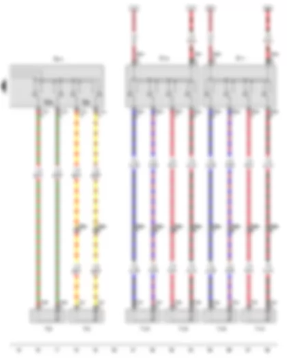
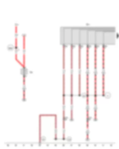
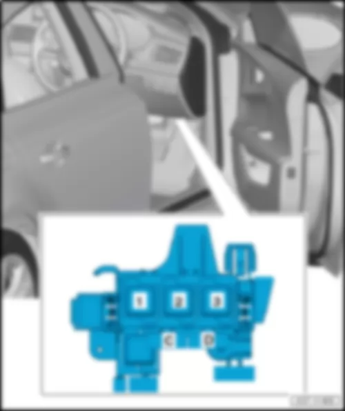
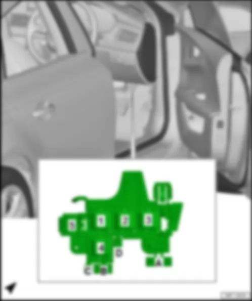
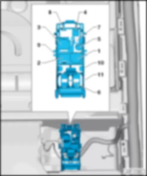
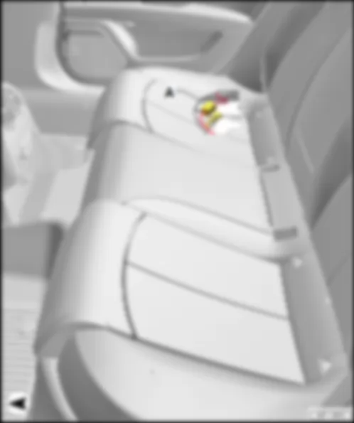
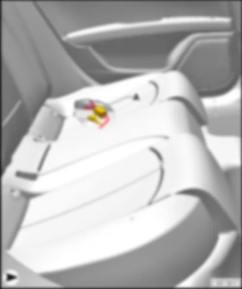
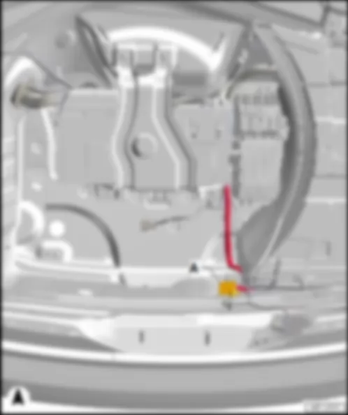
| E222 | Driver seat rake adjustment switch |
| E364 | Driver seat height adjustment switch |
| E470 | Driver seat adjustment operating unit |
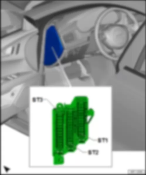
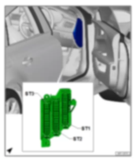
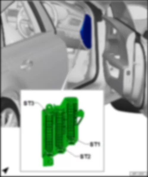
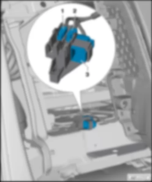
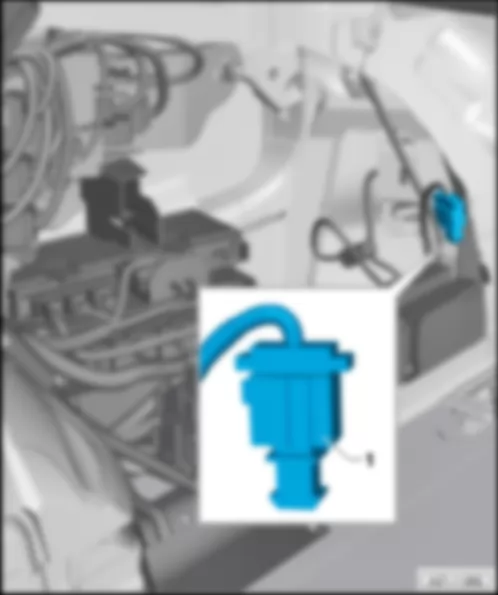
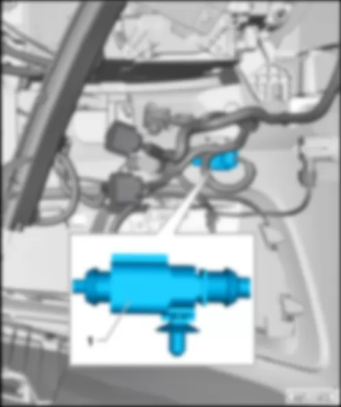
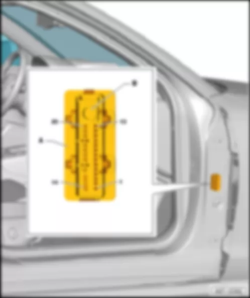
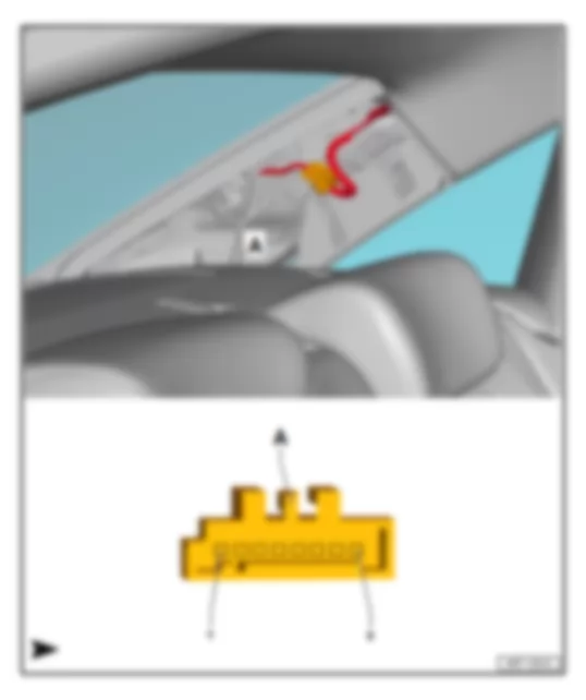
| S44 | Driver seat adjustment thermal fuse 1, in left A-pillar coupling station |
| S133 | Fuse 3 |
| T4ci | 4-pin connector |
| T4ck | 4-pin connector |
| T6bb | 6-pin connector |
| T10q | 10-pin connector |
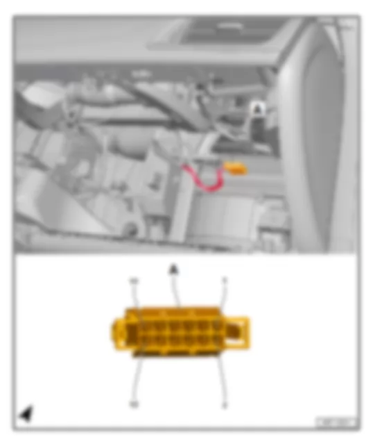
| T17m | 17-pin connector, in coupling point for front seat, left |
| V243 | Driver seat rake adjustment motor |
| V245 | Driver seat height adjustment motor |
| 34 | Earth point, under driver seat |
| 95 | Earth connection 1, in seat adjustment wiring harness |
| 371 | Earth connection 6, in main wiring harness |
| B316 | Positive connection 2 (30a) in main wiring harness |
| M1 | Positive connection 1 (30), in seat adjustment wiring harness |
| * | see applicable current flow diagram for fuse assignment |
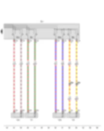
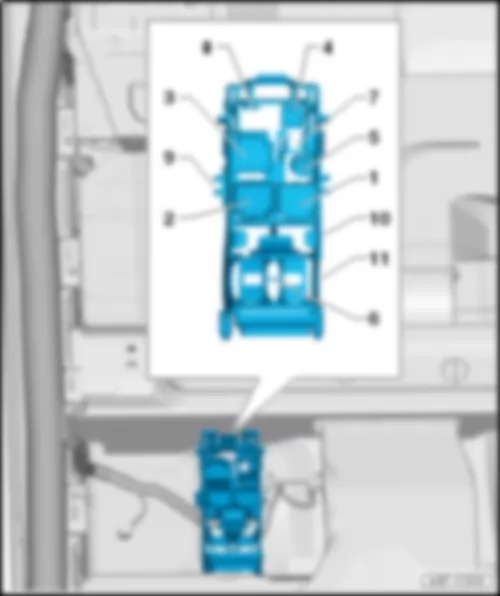
| E96 | Driver seat backrest adjustment switch |
| E176 | Driver seat lumbar support adjustment switch |
| E177 | Front passenger seat lumbar support adjustment switch |
| E363 | Driver seat longitudinal adjustment switch |
| E470 | Driver seat adjustment operating unit |
| T4ce | 4-pin connector |
| T4cl | 4-pin connector |
| T4cr | 4-pin connector |
| T4cs | 4-pin connector |
| T4ct | 4-pin connector |
| T4cu | 4-pin connector |
| T6bc | 6-pin connector |
| T6be | 6-pin connector |
| T8ad | 8-pin connector, in driver seat |
| T8ae | 8-pin connector, in front passenger seat |
| T10q | 10-pin connector |
| V28 | Driver seat longitudinal adjustment motor |
| V45 | Driver seat backrest adjustment motor |
| V125 | Driver seat lumbar support longitudinal adjustment motor |
| V126 | Front passenger seat lumbar support longitudinal adjustment motor |
| V129 | Driver seat lumbar support height adjustment motor |
| V130 | Front passenger seat lumbar support height adjustment motor |
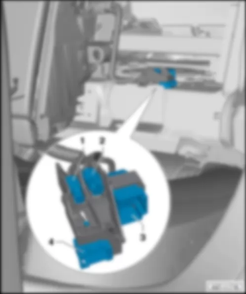
| E64 | Front passenger seat longitudinal adjustment switch |
| E98 | Front passenger seat backrest adjustment switch |
| E334 | Front passenger seat rake adjustment button |
| E365 | Front passenger seat height adjustment switch |
| E471 | Front passenger seat adjustment operating unit |
| T4cm | 4-pin connector |
| T4co | 4-pin connector |
| T4cp | 4-pin connector |
| T4cv | 4-pin connector |
| T8ae | 8-pin connector, in front passenger seat |
| T10s | 10-pin connector |
| V31 | Front passenger seat longitudinal adjustment motor |
| V46 | Front passenger seat backrest adjustment motor |
| V244 | Front passenger seat rake adjustment motor |
| V246 | Front passenger seat height adjustment motor |
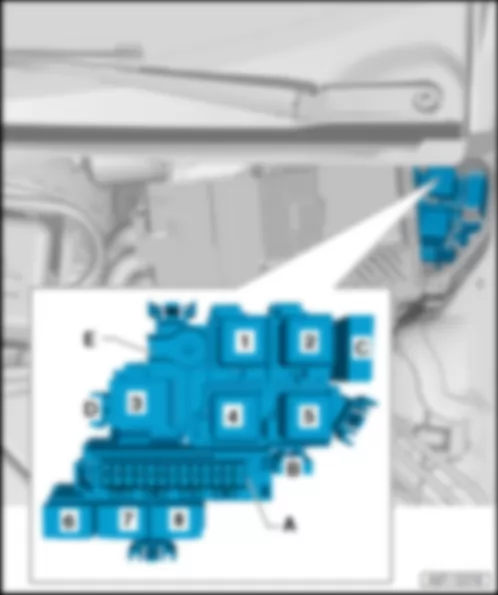
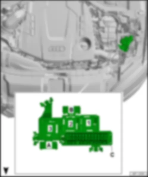
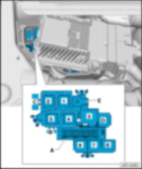
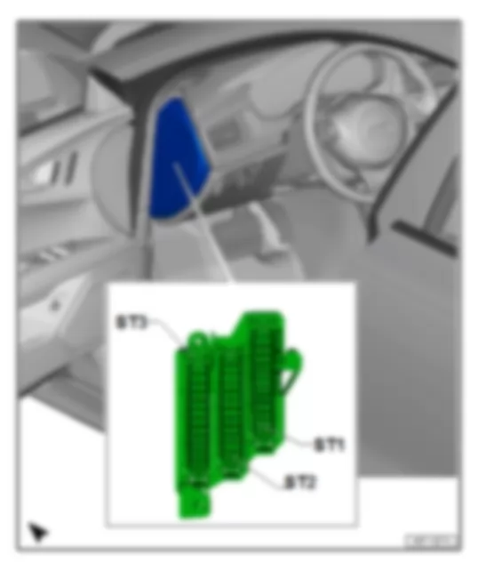
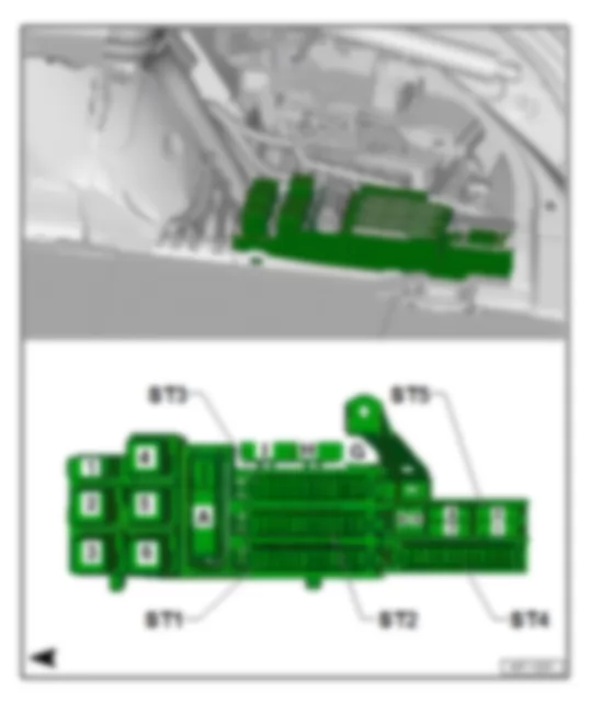
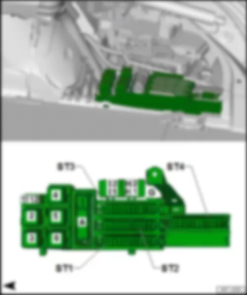
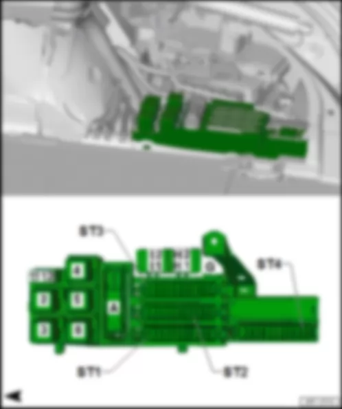
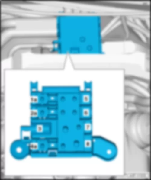
| No. | | Current Flow Diagram designation | Nominal value | | Function/component | Terminal |
| 1 | - | Fuse 1 on fuse holder A -SA1- | 10 A | - | Automatic gearbox control unit -J217-
Auxiliary hydraulic pump 1 for gearbox oil -V475-6) 7) 9) | 30 |
| 2 | - | Fuse 2 on fuse holder A -SA2- | 5 A | - | Oil level and oil temperature sender -G266- | 15 |
| 3 | - | Fuse 3 on fuse holder A -SA3- | 5 A | - | Engine control unit -J623-
Air mass meter -G70-4) | 15 |
| 4 | - | Fuse 4 on fuse holder A -SA4- | 5 A | - | Engine control unit -J623-
| 30 |
| 5 | - | Fuse 5 on fuse holder A -SA5- | 10 A | - | Actuator 1 for camshaft adjustment -F366-6) 9)
Actuator 2 for camshaft adjustment -F367-6) 9)
Actuator 3 for camshaft adjustment -F368-6) 9)
Actuator 4 for camshaft adjustment -F369-6) 9)
Actuator 5 for camshaft adjustment -F370-6) 9)
Actuator 6 for camshaft adjustment -F371-6) 9)
Actuator 7 for camshaft adjustment -F372-6) 9)
Actuator 8 for camshaft adjustment -F373-6) 9)
Fuel metering valve -N290-
Fuel pressure regulating valve -N276-4)
Fuel metering valve 2 -N402-3) 10) 11)
Magnetic clutch for supercharger -N421-8) | 87 |
| 6 | - | Fuse 6 on fuse holder A -SA6- | 15 A | - | Engine control unit -J623-
Map-controlled engine cooling system thermostat -F265-10)
Inlet cam actuator 1 for cylinder 2 -F452-10) 11)
Exhaust cam actuator 1 for cylinder 2 -F454-10) 11)
Inlet cam actuator 1 for cylinder 3 -F456-10) 11)
Exhaust cam actuator 1 for cylinder 3 -F458-10) 11)
Inlet cam actuator 1 for cylinder 5 -F464-10) 11)
Exhaust cam actuator 1 for cylinder 5 -F466-10) 11)
Secondary air pump relay -J299-10) 11)
Secondary air inlet valve -N112-10)
Turbocharger air recirculation valve, cylinder bank 2 -N427-10) 11)
Valve for oil pressure control -N428-10)
Secondary air inlet valve 2 -N320-10)
Coolant valve for cylinder head -N489-10)
Piston cooling jet control valve -N522-10)
Activated charcoal filter solenoid valve 1 -N80-10) 11)
Turbocharger air recirculation valve -N249-10) 11)
Intake manifold flap valve -N316-10) 11)
Continued coolant circulation pump -V51-10) 11)
Coolant circulation pump 2 -V178-10) 11)
Charge air cooling pump -V188-10) 11) | 87 |
| 7 | - | Fuse 7 on fuse holder A -SA7- | 15 A | - | Actuator 1 for camshaft adjustment -F366-2) 4) 5)
Actuator 12 for camshaft adjustment -F377-2) 5)
Camshaft control valve 1 -N205-
Camshaft control valve 2 -N208-1) 2) 3) 4) 5) 10) 11)
Intake manifold flap valve -N316-1) 4)
Exhaust camshaft control valve 1 -N318-2) 3) 5) 10) 11)
Exhaust camshaft control valve 2 -N319-2) 3) 5) 10) 11)
Charge pressure control solenoid valve -N75-3) 10) 11)
Valve for oil pressure control -N428-4)
Activated charcoal filter solenoid valve 1 -N80-4)
Turbocharger air recirculation valve -N249-4)
Coolant circulation pump -V50-1) 2) 3) 4)
Left electrohydraulic engine mounting solenoid valve -N144-6) 9)
Piston cooling jet control valve -N522-6) 9)
Right electrohydraulic engine mounting solenoid valve -N145-6) | 87 |
| 8 | - | Fuse 8 on fuse holder A -SA8- | 15 A | - | Injector 2, cylinder 1 -N532-8)
Injector 2, cylinder 2 -N533-8)
Injector 2, cylinder 3 -N534-8)
Injector 2, cylinder 4 -N535-8)
Injector 2, cylinder 5 -N536-8)
Injector 2, cylinder 6 -N537-8) | 87 |
| 9 | - | Fuse 9 on fuse holder A -SA9- | 5 A | - | Voltage stabilizer -J532-
Engine control unit -J623-2) 3) 4) 5) 8) 10) 11) | 50 |
| 10 | - | Fuse 10 on fuse holder A -SA10-
not assigned 11) | 15 A | - | Lambda probe heater -Z19-
Lambda probe -G39-
Lambda probe heater 2 -Z28-1) 2) 3) 4) 5) 7)
Lambda probe 2 -G108-1) 2) 3) 4) 5) 7)
Exhaust camshaft control valve 1 -N318-6) 9)
Intake manifold flap valve -N316-6) 9)
Activated charcoal filter solenoid valve 1 -N80-6) 9)
Turbocharger air recirculation valve -N249-6) 9)
Left electrohydraulic engine mounting solenoid valve -N144-6) 8) 9)
Right electrohydraulic engine mounting solenoid valve -N145-6) 8
Camshaft control valve 1 -N205-6) 9)
Coolant circulation pump -V50-6)
Pump for exhaust gas recirculation cooler -V400-8) | 30 |
| 11 | - | Fuse 11 on fuse holder A -SA11- | 5 A | - | Radiator fan control unit -J293-8) 10) 11)
Radiator fan control unit 2 -J671-1) 2) 3) 4) 8) 10) 11) | 87 |
| 12 | - | Fuse 12 on fuse holder A -SA12- | 5 A | - | Automatic gearbox control unit -J217- | 15 |
| 13 | - | Fuse 13 on fuse holder A -SA13- | 5 A | - | Gearbox oil cooling valve -N509-3) 6) 9) 10) 11) | 15 |
| 14 | - | Fuse 14 on fuse holder A -SA14- | 20 A
30 A 3) 11) | - | Ignition coil 1 with output stage -N70-
Ignition coil 2 with output stage -N127-
Ignition coil 3 with output stage -N291-
Ignition coil 4 with output stage -N292-
Ignition coil 5 with output stage -N323-
Ignition coil 6 with output stage -N324-
Ignition coil 7 with output stage -N325-3) 10) 11)
Ignition coil 8 with output stage -N326-3) 10) 11) | 30 |
| 15 | - | Fuse 15 on fuse holder A -SA15- | 15 A
20 A | - | Lambda probe heater -Z19-6) 7) 8) 9) 10) 11)
Lambda probe heater 2 -Z28-7) 8) 9) 10) 11)
Engine control unit -J623-3) | 87 |
| 16 | - | Fuse 16 on fuse holder A -SA16- | 15 A | - | Secondary air pump relay -J299-
Additional coolant pump relay -J496-1) 2) 3) 4)
Activated charcoal filter solenoid valve 1 -N80-
Secondary air inlet valve -N112-1) 2) 3)
Left electrohydraulic engine mounting solenoid valve -N144-1)
Right electrohydraulic engine mounting solenoid valve -N145-1)
Variable intake manifold changeover valve -N156-
Secondary air inlet valve 2 -N320-1) 3)
Valve for oil pressure control -N428-
Solenoid for coolant circuit -N492-
Crankcase breather shut-off valve -N548-2)
Charge air cooling pump -V188-1) 3)
Inlet cam actuator 1 for cylinder 2 -F452-3)
Coolant circulation pump 2 -V178-3)
Piston cooling jet control valve -N522-3)
Coolant valve for cylinder head -N489-3) 5)
Map-controlled engine cooling system thermostat -F265-3)
Turbocharger air recirculation valve, cylinder bank 2 -N427-3)
Turbocharger air recirculation valve -N249-3)
Intake manifold flap valve -N316-3)
not assigned 4)
Continued coolant circulation pump -V51-3)6)
Injector 2, cylinder 1 -N532-6) 9)
Injector 2, cylinder 2 -N533-6) 9)
Injector 2, cylinder 3 -N534-6) 9)
Injector 2, cylinder 4 -N535-6) 9)
Engine control unit -J623-6) 7) 8) 9) 11)
Inlet cam actuator 2 for cylinder 5 -F465-3) | 87 |
| 17 | - | Fuse 17 on fuse holder A -SA17-
not assigned 4) | 15 A | - | Lambda probe 1 heater after catalytic converter -Z29-1) 2) 3) 5) 9) 10) 11)
Lambda probe 2 heater after catalytic converter -Z30-1) 2) 3) 5) 10) 11) | 87 |
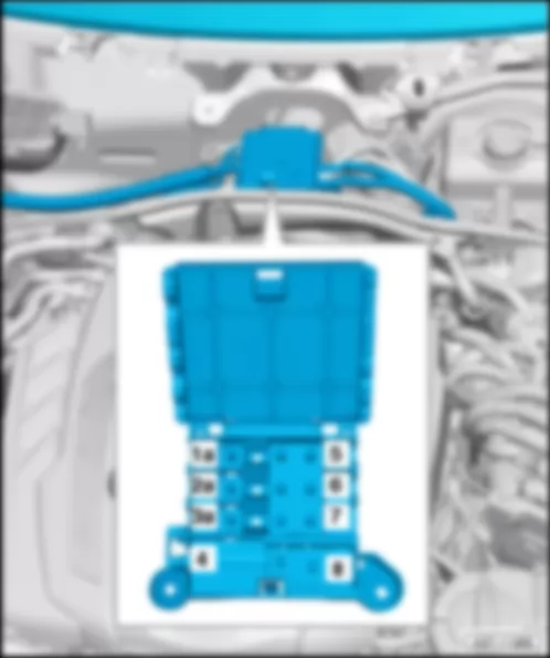
| No. | | Current Flow Diagram designation | Nominal value | | Function/component | Terminal |
| 1 | - | Fuse 1 on fuse holder A -SA1- | 10 A | - | Automatic gearbox control unit -J217-
Auxiliary hydraulic pump 1 for gearbox oil -V475-4) 6) | 30 |
| 2 | - | Fuse 2 on fuse holder A -SA2- | 5 A | - | Oil level and oil temperature sender -G266- | 15 |
| 3 | - | Fuse 3 on fuse holder A -SA3- | 5 A | - | Engine control unit -J623-
-J1021-5) 6) | 15 |
| 4 | - | Fuse 4 on fuse holder A -SA4- | 5 A | - | Engine control unit -J623- | 30 |
| 5 | - | Fuse 5 on fuse holder A -SA5- | 5 A | - | Air mass meter -G70- | 30 |
| 6 | - | Fuse 6 on fuse holder A -SA6- | 15 A | - | Engine control unit -J623- | 87 |
| 7 | - | Fuse 7 on fuse holder A -SA7- | 10 A | - | Fuel metering valve -N290-
Fuel pressure regulating valve -N276-
Camshaft control valve 1 -N205-7) | 30 |
| 8 | - | Fuse 8 on fuse holder A -SA8- | 10 A | - | Control unit for NOx sender -J583-2) 3) 4) 6) 7)
Control unit for NOx sender 2 -J881-2) 3) 4) 6)
NOx sender 2 -G687-5)
Particulate sensor -G784-5) 6) | 30 |
| 9 | - | Fuse 9 on fuse holder A -SA9- | 5 A | - | Voltage stabiliser -J532-
Engine control unit -J623-1) | 50 |
| 10 | - | Fuse 10 on fuse holder A -SA10- | 10 A | - | Lambda probe -G39-
Lambda probe heater -Z19- | 30 |
| 11 | - | Fuse 11 on fuse holder A -SA11- | 5 A | - | Radiator fan control unit -J293-
Radiator fan control unit 2 -J671-
Radiator fan -V7-
Airbag energy accumulator unit -J177- | 87 |
| 12 | - | Fuse 12 on fuse holder A -SA12- | 5 A | - | Automatic gearbox control unit -J217- | 15 |
| 13 | - | Fuse 13 on fuse holder A -SA13- | 5 A | - | Gearbox oil cooling valve -N509-
not assigned1) 2) 7) | 15 |
| 14 | - | Fuse 14 on fuse holder A -SA14- | 5 A 1)
10 A 7)
15 A 4) | - | Pump for exhaust gas recirculation cooler -V400-1) 4) 5)
Valve for oil pressure control -N428-7)
Coolant valve for cylinder head -N489-7)
Charge air cooling pump -V188-7)
Auxiliary pump for heating -V488-7) | 30 |
| 15 | - | Fuse 15 on fuse holder A -SA15- | 30 A
35 A | - | Fuse 3 on fuse holder B -SB3-
fuse carrier 3 -ST3-4) 5) | 87 |
| 16 | - | Fuse 16 on fuse holder A -SA16- | 15 A | - | Map-controlled engine cooling system thermostat -F265-2) 3)
Low heat output relay -J359-
High heat output relay -J360-
Secondary air inlet valve -N112-2)
Left electrohydraulic engine mounting solenoid valve -N144-
Right electrohydraulic engine mounting solenoid valve -N145-
Exhaust gas recirculation cooler changeover valve -N345-
Valve for oil pressure control -N428-2) 3)
Charge pressure control solenoid valve -N75-1) 3) 7)
Heater element for crankcase breather -N79-1)
Coolant valve for cylinder head -N489-3)
Turbine changeover valve -N529-3)
Automatic glow period control unit -J179-4) 5) 6) 7) | 30 |
| 17 | - | not assigned | | - | | |
| No. | | Current Flow Diagram designation | Nominal value | | Function/component | Terminal |
| 1 | - | Fuse 1 on fuse holder A -SA1- | 15 A | - | Automatic gearbox control unit -J217- | 30 |
| 2 | - | Fuse 2 on fuse holder A -SA2- | 5 A | - | Oil level and oil temperature sender -G266- | 15 |
| 3 | - | Fuse 3 on fuse holder A -SA3- | 5 A | - | Engine control unit -J623-
Air mass meter -G70-
Power and control electronics for electric drive -JX1- | 15 |
| 4 | - | Fuse 4 on fuse holder A -SA4- | 5 A | - | Engine control unit -J623- | 30 |
| 5 | - | Fuse 5 on fuse holder A -SA5- | 10 A | - | Fuel metering valve -N290-
Fuel pressure regulating valve -N276-
Solenoid for coolant circuit -N492- | 87 |
| 6 | - | Fuse 6 on fuse holder A -SA6- | 15 A | - | Engine control unit -J623- | 87 |
| 7 | - | Fuse 7 on fuse holder A -SA7- | 15 A | - | Actuator 1 for camshaft adjustment -F366-
Camshaft control valve 1 -N205-
Intake manifold flap valve -N316-
Charge pressure control solenoid valve -N75-
Valve for oil pressure control -N428-
Activated charcoal filter solenoid valve 1 -N80-
Turbocharger air recirculation valve -N249-
Right electrohydraulic engine mounting solenoid valve -N145-
Left electrohydraulic engine mounting solenoid valve -N144-
Secondary air inlet valve -N112-
Secondary air pump relay -J299-
Coolant pump -V36-
Coolant pump for high-temperature circuit -V467-
Coolant circulation pump -V50- | 87 |
| 8 | - | Fuse 8 on fuse holder A -SA8- | 5 A | - | Power and control electronics for electric drive -JX1- | 30 |
| 9 | - | Fuse 9 on fuse holder A -SA9- | 5 A | - | Voltage stabilizer -J532-
Engine control unit -J623- | 50 |
| 10 | - | Fuse 10 on fuse holder A -SA10- | 15 A | - | Lambda probe heater -Z19-
Lambda probe -G39-
Lambda probe after catalytic converter -G130-
Lambda probe 1 heater after catalytic converter -Z29- | 30 |
| 11 | - | Fuse 11 on fuse holder A -SA11- | 5 A | - | Radiator fan control unit -J293-
Radiator fan -V7-
Radiator fan control unit 2 -J671-
Radiator fan 2 -V177- | 87 |
| 12 | - | Fuse 12 on fuse holder A -SA12- | 5 A | - | Automatic gearbox control unit -J217- | 15 |
| 13 | - | Fuse 13 on fuse holder A -SA13- | 5 A | - | Radiator fan control unit -N509-
Control unit for air conditioning compressor -J842-
Electrical air conditioner compressor -V470- | 15 |
| 14 | - | Fuse 14 on fuse holder A -SA14- | 20 A | - | Ignition coil 1 with output stage -N70-
Ignition coil 2 with output stage -N127-
Ignition coil 3 with output stage -N291-
Ignition coil 4 with output stage -N292- | 30 |
| 15 | - | not assigned | | - | | |
| 16 | - | Fuse 16 on fuse holder A -SA16- | 15 A | - | Secondary air pump relay -J299-
Additional coolant pump relay -J496-
Activated charcoal filter solenoid valve 1 -N80-
Variable intake manifold changeover valve -N156-
Valve for oil pressure control -N428-
Solenoid for coolant circuit -N492- | 87 |
| 17 | - | Fuse 17 on fuse holder A -SA17- | 10 A | - | Low-temperature circuit coolant pump -V468- | 87 |
| No. | | Current Flow Diagram designation | Nominal value | | Function/component | Terminal |
| 1 | - | Fuse 1 on fuse holder A -SA1- | 15 A
10 A4) | - | Automatic gearbox control unit -J217- | 30 |
| 2 | - | Fuse 2 on fuse holder A -SA2- | 5 A | - | Oil level and oil temperature sender -G266- | 15 |
| 3 | - | Fuse 3 on fuse holder A -SA3- | 5 A | - | Engine control unit -J623-
Catalytic converter heater control unit 1 -J1021-1) 2) | 15 |
| 4 | - | Fuse 4 on fuse holder A -SA4- | 5 A | - | Engine control unit -J623- | 30 |
| 5 | - | Fuse 5 on fuse holder A -SA5- | 5 A | - | Air mass meter -G70- | 30 |
| 6 | - | Fuse 6 on fuse holder A -SA6- | 15 A | - | Engine control unit -J623- | 87 |
| 7 | - | Fuse 7 on fuse holder A -SA7- | 10 A | - | Fuel metering valve -N290-
Fuel pressure regulating valve -N276- | 30 |
| 8 | | Fuse 8 on fuse holder A -SA8- | 10 A1) 2)
5 A | - | Control unit for NOx sender -J583-2)
Control unit for NOx sender 2 -J881-
Particulate sensor -G784-2) | 30 |
| 9 | - | Fuse 9 on fuse holder A -SA9- | 5 A | - | Voltage stabilizer -J532-
Engine control unit -J623- | 50 |
| 10 | - | Fuse 10 on fuse holder A -SA10- | 10 A | - | Lambda probe -G39-
Lambda probe heater -Z19- | 30 |
| 11 | - | Fuse 11 on fuse holder A -SA11- | 5 A | - | Radiator fan control unit -J293-
Radiator fan control unit 2 -J671- | 87 |
| 12 | - | Fuse 12 on fuse holder A -SA12- | 5 A | - | Automatic gearbox control unit -J217- | 30 |
| 13 | - | Fuse 13 on fuse holder A -SA13- | 5 A | - | Gearbox oil cooling valve -N509- | 30 |
| 14 | - | not assigned | | - | | |
| 15 | - | Fuse 15 on fuse holder A -SA15- | 35 A | - | B635 positive connection 3 (87) in main wiring harness
Supply, fuse holder B -SB-
Fuse carrier 3 -ST3-3) 5) | 87 |
| 16 | - | Fuse 16 on fuse holder A -SA16- | 15 A | - | Map-controlled engine cooling system thermostat -F265-
Low heat output relay -J359-
High heat output relay -J360-
Left electrohydraulic engine mounting solenoid valve -N144-
Right electrohydraulic engine mounting solenoid valve -N145-
Exhaust gas recirculation cooler changeover valve -N345-
Valve for oil pressure control -N428-1) 2)
Charge pressure control solenoid valve -N75-2)
Coolant valve for cylinder head -N489-
Coolant valve for cylinder head -N529-2)
Automatic glow period control unit -J179- | 30 |
| 17 | - | not assigned | | - | | |
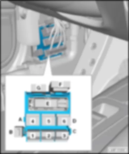
| No. | | Current Flow Diagram designation | Nominal value | | Function/component | Terminal |
| 1 | - | Fuse 1 on fuse holder B -SB1- | 5 A | - | TCS and ESP button -E256-
Control unit for air ionisation system -J897-
Power steering control unit -J500-
Seat heating control unit -J882-
Trailer detector control unit -J345-
Electromechanical parking brake button -E538-
Front passenger side airbag deactivated warning lamp -K145- | 15 |
| 2 | - | Fuse 2 on fuse holder B -SB2- | 5 A | - | Relay for automatic anti-dazzle interior mirror -J910-
Automatic anti-dazzle interior mirror -Y7- | 15 |
| 3 | - | Fuse 3 on fuse holder B -SB3- | 10 A | - | Engine sound generator control unit -J943-1) | 15 |
| 4 | - | Fuse 4 on fuse holder B -SB4- | 5 A | - | Control unit for sensor electronics -J849- | 15 |
| 5 | - | Fuse 5 on fuse holder B -SB5- | 5 A | - | ABS control unit -J104- | 15 |
| 6 | - | Fuse 6 on fuse holder B -SB6- | 5 A | - | Air quality sensor -G238-
Refrigerant pressure and temperature sender -G395-
Humidity sender in fresh air intake duct -G657- | 15 |
| 7 | - | Fuse 7 on fuse holder B -SB7- | 10 A | - | Adaptive cruise control unit -J428-
Control unit 2 for adaptive cruise control -J850- | 15 |
| 8 | - | Fuse 8 on fuse holder B -SB8- | 5 A | - | Airbag control unit -J234-
Seat occupied recognition control unit -J706- | 15 |
| 9 | - | Fuse 9 on fuse holder B -SB9- | 5 A | - | Data bus diagnostic interface -J533- | 15 |
| 10 | - | Fuse 10 on fuse holder B -SB10- | 5 A | - | Garage door operating unit -E284-
Garage door operation control unit -J530-
Control unit for night vision system -J853-
Control unit for structure-borne sound -J869-1) | 15 |
| 11 | - | Fuse 11 on fuse holder B -SB11- | 10 A | - | Image processing control unit -J851-
Camera control unit -J852- | 15 |
| 12 | - | Fuse 12 on fuse holder B -SB12- | 5 A | - | Active steering control unit -J792- | 15 |
| 13 | - | Fuse 13 on fuse holder B -SB13- | 15 A | - | to fuse holder F -SF- | 15 |
| 14 | - | Fuse 14 on fuse holder B -SB14- | 30 A | - | to fuse holder C -SC- | 15 |
| 15 | - | Fuse 15 on fuse holder B -SB15- | 15 A | - | Fuse 3 on fuse holder A -SA3-
Fuse 12 on fuse holder A -SA12-
Fuse 13 on fuse holder A -SA13- | 15 |
| 16 | - | Fuse 16 on fuse holder B -SB16- | 40 A | - | Engine control unit -J623-
Starter motor relay 2 -J695-
Starter motor relay -J53- | 15 |
| No. | | Current Flow Diagram designation | Nominal value | | Function/component | Terminal |
| 1 | - | Fuse 1 on fuse holder B -SB1- | 5 A | - | TCS and ESP button -E256-
Control unit for air ionisation system -J897-
Power steering control unit -J500-
Seat heating control unit -J882-
Trailer detector control unit -J345-
Electromechanical parking brake button -E538-
High heat output relay -J360-
Headlight range control unit -J431-
Power unit mounting control unit -J931-
Low heat output relay -J359-
Auxiliary air heater control unit -J604- | 15 |
| 2 | - | Fuse 2 on fuse holder B -SB2- | 5 A | - | Relay for automatic anti-dazzle interior mirror -J910-
Automatic anti-dazzle interior mirror -Y7-
Refrigerant pressure and temperature sender -G395-
Humidity sender in fresh air intake duct -G657-
Air quality sensor -G238-
16-pin connector -T16- , Diagnostic connector
Toll collection sender -G459-2) | 15 |
| 3 | - | not assigned | | - | | |
| 4 | - | Fuse 4 on fuse holder B -SB4- | 5 A | - | Onboard supply control unit -J519-
Park assist steering control unit -J791-
Parking aid control unit -J446- | 15 |
| 5 | - | Fuse 5 on fuse holder B -SB5- | 5 A | - | ABS control unit -J104-
Control unit for sensor electronics -J849-
Active steering control unit -J792- | 15 |
| 6 | - | Fuse 6 on fuse holder B -SB6- | 10 A | - | Onboard supply control unit -J519- , right LED headlight | 15 |
| 7 | - | Fuse 7 on fuse holder B -SB7- | 10 A | - | Adaptive cruise control unit -J428-
Control unit 2 for adaptive cruise control -J850- | 15 |
| 8 | - | Fuse 8 on fuse holder B -SB8- | 5 A | - | Airbag control unit -J234-
Seat occupied recognition control unit -J706- | 15 |
| 9 | - | Fuse 9 on fuse holder B -SB9- | 5 A | - | Data bus diagnostic interface -J533- | 15 |
| 10 | - | Fuse 10 on fuse holder B -SB10- | 5 A
7.5 A 1) | - | Garage door operating unit -E284-
Garage door operation control unit -J530-
Control unit for night vision system -J853-
Control unit for structure-borne sound -J869-
Reversing camera system control unit -J772-1) | 15 |
| 11 | - | Fuse 11 on fuse holder B -SB11- | 10 A | - | Image processing control unit -J851-
Camera control unit -J852- | 15 |
| 12 | - | Fuse 12 on fuse holder B -SB12- | 10 A | - | Onboard supply control unit -J519- , left LED headlight | 15 |
| 13 | - | Fuse 13 on fuse holder B -SB13- | 5 A | - | Steering column electronics control unit -J527- | 15 |
| 14 | - | Fuse 14 on fuse holder B -SB14- | 30 A | - | to fuse holder F -SF- | 15 |
| 15 | - | Fuse 15 on fuse holder B -SB15- | 15 A | - | Fuse 3 on fuse holder A -SA3-
Fuse 12 on fuse holder A -SA12-
Fuse 13 on fuse holder A -SA13- | 15 |
| 16 | - | Fuse 16 on fuse holder B -SB16- | 40 A | - | Engine control unit -J623-
Starter motor relay 2 -J695-
Starter motor relay -J53- | 15 |
| No. | | Current Flow Diagram designation | Nominal value | | Function/component | Terminal |
| 1 | - | Fuse 1 on fuse holder B -SB1- | 5 A | - | Data bus diagnostic interface -J533- | 30 |
| 2 | - | Fuse 2 on fuse holder B -SB2- | 10 A | - | Operating and display unit for rear air conditioning system -E265- | 30 |
| 3 | - | Fuse 3 on fuse holder B -SB3- | 10 A | - | ABS control unit -J104- | 30 |
| 4 | - | Fuse 4 on fuse holder B -SB4- | 30 A | - | Driver door control unit -J386- | 30 |
| 5 | - | Fuse 5 on fuse holder B -SB5- | 7.5 A | - | Control unit for driver multicontour seat -J873- | 30 |
| 6 | - | Fuse 6 on fuse holder B -SB6- | 35 A | - | Active steering control unit -J792- | 30 |
| 7 | - | Fuse 7 on fuse holder B -SB7- | 20 A | - | Sliding sunroof adjustment control unit -J245-
Sliding sunroof motor -V1- | 30 |
| 8 | - | Fuse 8 on fuse holder B -SB8- | 15 A | - | Rear left door control unit -J388- | 30 |
| 9 | - | Fuse 9 on fuse holder B -SB9- | 5 A | - | Front passenger seat lumbar support adjustment switch -E177- | 30 |
| 10 | - | Fuse 10 on fuse holder B -SB10- | 30 A
5 A4) | - | Auxiliary heater control unit -J364-
Tyre Pressure Monitoring System control unit -J502-4) | 30 |
| 11 | - | Fuse 11 on fuse holder B -SB11- | 20 A | - | Sliding sunroof adjustment control unit -J245-1)
Sliding sunroof motor -V1-1)
Sunroof roller blind control unit -J394-2)
Sunroof roller blind motor -V260-2) | 30 |
| 12 | - | Fuse 12 on fuse holder B -SB12- | 15 A | - | Driver door control unit -J386-3) | 30 |
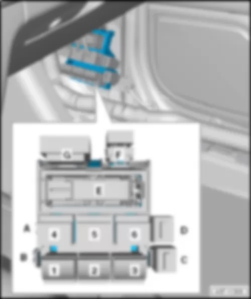
| No. | | Current Flow Diagram designation | Nominal value | | Function/component | Terminal |
| 1 | - | Fuse 1 on fuse holder B -SB1- | 5 A | - | Connection for external audio sources -R199- | 30 |
| 2 | - | Fuse 2 on fuse holder B -SB2- | 5 A | - | Aerial amplifier for mobile telephone -R86-
Telephone bracket -R126- | 30 |
| 3 | - | Fuse 3 on fuse holder B -SB3- | 7.5 A | - | Control unit for front passenger multicontour seat -J872- | 30 |
| 4 | - | not assigned | | - | | |
| 5 | - | Fuse 5 on fuse holder B -SB5- | 5 A | - | Control unit for sensor electronics -J849- | 30 |
| 6 | - | Fuse 6 on fuse holder B -SB6- | 5 A | - | Anti-theft alarm sensor -G578-
Alarm horn -H12-
Interior monitoring sensor -G273-
Vehicle inclination sender -G384- | 30 |
| 7 | - | Fuse 7 on fuse holder B -SB7- | 5 A | - | Electromechanical parking brake button -E538-
Terminal 15 voltage supply relay -J329- | 30 |
| 8 | - | Fuse 8 on fuse holder B -SB8- | 5 A | - | Roof electronics control unit -J528- | 30 |
| 9 | - | Fuse 9 on fuse holder B -SB9- | 5 A | - | Onboard supply control unit -J519-
Rain and light sensor -G397-
Windscreen heater for lane departure warning -Z67- | 30 |
| 10 | - | Fuse 10 on fuse holder B -SB10- | 5 A | - | Driver seat lumbar support adjustment switch -E176- | 30 |
| 11 | - | Fuse 11 on fuse holder B -SB11- | 7.5 A | - | Control unit for driver multicontour seat -J873- | 30 |
| 12 | - | Fuse 12 on fuse holder B -SB12- | 10 A | - | ABS control unit -J104- | 30 |
| 13 | - | Fuse 13 on fuse holder B -SB13- | 15 A | - | Horn relay -J413- | 30 |
| 14 | - | Fuse 14 on fuse holder B -SB14- | 30 A | - | Onboard supply control unit -J519- | 30 |
| 15 | - | Fuse 15 on fuse holder B -SB15- | 30 A | - | Onboard supply control unit -J519- | 30 |
| 16 | - | Fuse 16 on fuse holder B -SB16- | 35 A | - | Active steering control unit -J792- | 30 |
| No. | | Current Flow Diagram designation | Nominal value | | Function/component | Terminal |
| 1 | - | Fuse 1 on fuse holder B -SB1- | 5 A
25 A 3) | - | Clutch position sender -G476-
Relay for vacuum pump -J318-3) | 30 |
| 2 | - | Fuse 2 on fuse holder B -SB2- | 25 A
5 A 4) 5) | - | Fuel pump control unit -J538-
Fuel pump relay -J17-4) 5) | 30 |
| 3 | - | Fuse 3 on fuse holder B -SB3- | 5 A | - | Brake light switch -F-
Brake pedal position sender -G100- | 87 |
| 4 | - | Fuse 4 on fuse holder B -SB4- | 7.5 A1) 4)
5 A2) | - | Exhaust flap control unit -J883-1) 4)
Exhaust flap control unit 2 -J945-1) 4)
Control unit for reducing agent metering system -J880-2) | 30 |
| 5 | - | Fuse 5 on fuse holder B -SB5- | 30 A | - | Rear left door control unit -J388- | 30 |
| 6 | - | Fuse 6 on fuse holder B -SB6- | 7.5 A | - | Control unit for front passenger multicontour seat -J872- | 30 |
| 7 | - | Fuse 7 on fuse holder B -SB7- | 15 A | - | Treble horn -H2-
Bass horn -H7-
Horn relay -J413- | 30 |
| 8 | - | Fuse 8 on fuse holder B -SB8- | 30 A | - | Wiper motor control unit -J400-
Windscreen wiper motor -V- | 30 |
| 9 | - | Fuse 9 on fuse holder B -SB9- | 5 A | - | Rain and light sensor -G397- | 30 |
| 10 | - | Fuse 10 on fuse holder B -SB10- | 5 A | - | Driver seat lumbar support adjustment switch -E176- | 30 |
| 11 | - | Fuse 11 on fuse holder B -SB11- | 15 A | - | Front passenger door control unit -J387- | 30 |
| 12 | - | Fuse 12 on fuse holder B -SB12- | 15 A | - | Rear right door control unit -J389- | 30 |
| No. | | Current Flow Diagram designation | Nominal value | | Function/component | Terminal |
| 1 | - | Fuse 1 on fuse holder B -SB1- | 5 A | - | Clutch position sender -G476- | 87 |
| 2 | - | Fuse 2 on fuse holder B -SB2- | 25 A
5 A 3) 4) | - | Fuel pump control unit -J538-
Relay for reducing agent metering system -J963-2)
Fuel pump relay -J17-3) 4) | 87 |
| 3 | - | Fuse 3 on fuse holder B -SB3- | 5 A | - | Brake light switch -F-
Brake pedal position sender -G100- | 87 |
| 4 | - | Fuse 4 on fuse holder B -SB4- | 7.5 A1) 3)
5 A2) | - | Exhaust flap control unit -J883-1) 3)
Exhaust flap control unit 2 -J945-1) 3)
Control unit for reducing agent metering system -J880-2) | 87 |
| 5 | - | Fuse 5 on fuse holder B -SB5- | 30 A | - | Rear left door control unit -J388- | 30 |
| 6 | - | Fuse 6 on fuse holder B -SB6- | 30 A | - | Driver door control unit -J386- | 30 |
| 7 | - | Fuse 7 on fuse holder B -SB7- | 20 A | - | ABS control unit -J104- | 30 |
| 8 | - | Fuse 8 on fuse holder B -SB8- | 30 A | - | Wiper motor control unit -J400-
Windscreen wiper motor -V- | 30 |
| 9 | - | Fuse 9 on fuse holder B -SB9- | 35 A | - | Onboard supply control unit -J519- | 30 |
| 10 | - | Fuse 10 on fuse holder B -SB10- | 20 A | - | Onboard supply control unit -J519- | 30 |
| 11 | - | Fuse 11 on fuse holder B -SB11- | 30 A | - | Onboard supply control unit -J519- | 30 |
| 12 | - | Fuse 12 on fuse holder B -SB12- | 20 A | - | Sliding sunroof adjustment control unit -J245-
Sliding sunroof motor -V1- | 30 |
| No. | | Current Flow Diagram designation | Nominal value | | Function/component | Terminal |
| 1 | - | Fuse 1 on fuse holder B -SB1- | 5 A | - | TCS and ESP button -E256-
Control unit for air ionisation system -J897-
Power steering control unit -J500-
Seat heating control unit -J882-
Trailer detector control unit -J345-
Electromechanical parking brake button -E538-
Front passenger side airbag deactivated warning lamp -K145-
Multimedia system operating unit 2 -E499-
Power unit mounting control unit -J931- | 15 |
| 2 | - | Fuse 2 on fuse holder B -SB2- | 5 A | - | Relay for automatic anti-dazzle interior mirror -J910-
Automatic anti-dazzle interior mirror -Y7- | 15 |
| 3 | - | Fuse 3 on fuse holder B -SB3- | 10 A | - | Engine sound generator control unit -J943-1) | 15 |
| 4 | - | Fuse 4 on fuse holder B -SB4- | 5 A | - | Control unit for sensor electronics -J849- | 15 |
| 5 | - | Fuse 5 on fuse holder B -SB5- | 5 A | - | ABS control unit -J104- | 15 |
| 6 | - | Fuse 6 on fuse holder B -SB6- | 5 A | - | Air quality sensor -G238-
Refrigerant pressure and temperature sender -G395-
Humidity sender in fresh air intake duct -G657- | 15 |
| 7 | - | Fuse 7 on fuse holder B -SB7- | 10 A | - | Adaptive cruise control unit -J428-
Control unit 2 for adaptive cruise control -J850- | 15 |
| 8 | - | Fuse 8 on fuse holder B -SB8- | 5 A | - | Airbag control unit -J234-
Seat occupied recognition control unit -J706- | 15 |
| 9 | - | Fuse 9 on fuse holder B -SB9- | 5 A | - | Data bus diagnostic interface -J533- | 15 |
| 10 | - | Fuse 10 on fuse holder B -SB10- | 5 A | - | Garage door operating unit -E284-
Garage door operation control unit -J530-
Control unit for night vision system -J853-
Control unit for structure-borne sound -J869- | 15 |
| 11 | - | Fuse 11 on fuse holder B -SB11- | 10 A | - | Image processing control unit -J851-
Camera control unit -J852- | 15 |
| 12 | - | Fuse 12 on fuse holder B -SB12- | 5 A | - | Active steering control unit -J792- | 15 |
| 13 | - | Fuse 13 on fuse holder B -SB13- | 15 A | - | to fuse holder F -SF- | 15 |
| 14 | - | Fuse 14 on fuse holder B -SB14- | 30 A | - | to fuse holder C -SC- | 15 |
| 15 | - | Fuse 15 on fuse holder B -SB15- | 15 A | - | Fuse 3 on fuse holder A -SA3-
Fuse 12 on fuse holder A -SA12-
Fuse 13 on fuse holder A -SA13- | 15 |
| 16 | - | Fuse 16 on fuse holder B -SB16- | 40 A | - | Engine control unit -J623-
Starter motor relay 2 -J695-
Starter motor relay -J53- | 15 |
| No. | | Current Flow Diagram designation | Nominal value | | Function/component | Terminal |
| 1 | - | Fuse 1 on fuse holder B -SB1- | 5 A | - | TCS and ESP button -E256-
Power steering control unit -J500-
Seat heating control unit -J882-
Trailer detector control unit -J345-
Electromechanical parking brake button -E538-
Headlight range control unit -J431-
Power unit mounting control unit -J931- | 15 |
| 2 | - | Fuse 2 on fuse holder B -SB2- | 5 A | - | Relay for automatic anti-dazzle interior mirror -J910-
Automatic anti-dazzle interior mirror -Y7-
Air quality sensor -G238-
Refrigerant pressure and temperature sender -G395-
Humidity sender in fresh air intake duct -G657-
16-pin connector -T16- , diagnostic connector | 15 |
| 3 | - | not assigned | | - | | |
| 4 | - | Fuse 4 on fuse holder B -SB4- | 5 A | - | Onboard supply control unit -J519-
Park assist steering control unit -J791-
Parking aid control unit -J446- | 15 |
| 5 | - | Fuse 5 on fuse holder B -SB5- | 5 A | - | ABS control unit -J104-
Control unit for sensor electronics -J849-
Active steering control unit -J792- | 15 |
| 6 | - | Fuse 6 on fuse holder B -SB6- | 10 A | - | Onboard supply control unit -J519- , left LED headlight | 15 |
| 7 | - | Fuse 7 on fuse holder B -SB7- | 10 A | - | Adaptive cruise control unit -J428-
Control unit 2 for adaptive cruise control -J850- | 15 |
| 8 | - | Fuse 8 on fuse holder B -SB8- | 5 A | - | Airbag control unit -J234-
Seat occupied recognition control unit -J706- | 15 |
| 9 | - | Fuse 9 on fuse holder B -SB9- | 5 A | - | Data bus diagnostic interface -J533- | 15 |
| 10 | - | Fuse 10 on fuse holder B -SB10- | 5 A
7.5 A 1) | - | Garage door operating unit -E284-
Garage door operation control unit -J530-
Control unit for night vision system -J853-
Control unit for structure-borne sound -J869-
Reversing camera system control unit -J772-1) | 15 |
| 11 | - | Fuse 11 on fuse holder B -SB11- | 10 A | - | Image processing control unit -J851-
Camera control unit -J852- | 15 |
| 12 | - | Fuse 12 on fuse holder B -SB12- | 10 A | - | Onboard supply control unit -J519- , right LED headlight | 15 |
| 13 | - | Fuse 13 on fuse holder B -SB13- | 5 A | - | Steering column electronics control unit -J527- | 15 |
| 14 | - | Fuse 14 on fuse holder B -SB14- | 30 A | - | to fuse holder F -SF- | 15 |
| 15 | - | Fuse 15 on fuse holder B -SB15- | 15 A | - | Fuse 3 on fuse holder A -SA3-
Fuse 12 on fuse holder A -SA12-
Fuse 13 on fuse holder A -SA13- | 15 |
| 16 | - | Fuse 16 on fuse holder B -SB16- | 40 A | - | Engine control unit -J623-
Starter motor relay 2 -J695-
Starter motor relay -J53- | 15 |
| No. | | Current Flow Diagram designation | Nominal value | | Function/component | Terminal |
| 1 | - | Fuse 1 on fuse holder B -SB1- | 5 A | - | Front passenger seat lumbar support adjustment switch -E177- | 30 |
| 2 | - | Fuse 2 on fuse holder B -SB2- | 10 A | - | Operating and display unit for rear air conditioning system -E265- | 30 |
| 3 | - | Fuse 3 on fuse holder B -SB3- | 10 A | - | ABS control unit -J104- | 30 |
| 4 | - | Fuse 4 on fuse holder B -SB4- | 30 A | - | Driver door control unit -J386- | 30 |
| 5 | - | Fuse 5 on fuse holder B -SB5- | 7.5 A | - | Control unit for front passenger multicontour seat -J872- | 30 |
| 6 | - | Fuse 6 on fuse holder B -SB6- | 35 A | - | Active steering control unit -J792- | 30 |
| 7 | - | Fuse 7 on fuse holder B -SB7- | 20 A | - | Sliding sunroof adjustment control unit -J245-
Sliding sunroof motor -V1- | 30 |
| 8 | - | Fuse 8 on fuse holder B -SB8- | 5 A | - | Driver seat lumbar support adjustment switch -E176- | 30 |
| 9 | - | Fuse 9 on fuse holder B -SB9- | 30 A | - | Onboard supply control unit -J519- | 30 |
| 10 | - | Fuse 10 on fuse holder B -SB10- | 20 A | - | Sliding sunroof adjustment control unit -J245-
Sliding sunroof motor -V1- | 30 |
| 11 | - | Fuse 11 on fuse holder B -SB11- | 5 A | - | Anti-theft alarm sensor -G578-
Alarm horn -H12- | 30 |
| 12 | - | Fuse 12 on fuse holder B -SB12- | 15 A | - | Driver door control unit -J386- | 30 |
| No. | | Current Flow Diagram designation | Nominal value | | Function/component | Terminal |
| 1 | - | Fuse 1 on fuse holder B -SB1- | 5 A | - | Connection for external audio sources -R199- | 30 |
| 2 | - | Fuse 2 on fuse holder B -SB2- | 5 A | - | Aerial amplifier for mobile telephone -R86-
Telephone bracket -R126- | 30 |
| 3 | - | Fuse 3 on fuse holder B -SB3- | 7.5 A | - | Control unit for driver multicontour seat -J873- | 30 |
| 4 | - | not assigned | | - | | |
| 5 | - | Fuse 5 on fuse holder B -SB5- | 5 A | - | Control unit for sensor electronics -J849- | 30 |
| 6 | - | Fuse 6 on fuse holder B -SB6- | 5 A | - | Anti-theft alarm sensor -G578-
Alarm horn -H12-
Interior monitoring sensor -G273-
Vehicle inclination sender -G384- | 30 |
| 7 | - | Fuse 7 on fuse holder B -SB7- | 5 A | - | Electromechanical parking brake button -E538- | 30 |
| 8 | - | Fuse 8 on fuse holder B -SB8- | 5 A | - | Roof electronics control unit -J528- | 30 |
| 9 | - | Fuse 9 on fuse holder B -SB9- | 5 A | - | Rain and light sensor -G397- | 30 |
| 10 | - | Fuse 10 on fuse holder B -SB10- | 5 A | - | Driver seat lumbar support adjustment switch -E176- | 30 |
| 11 | - | Fuse 11 on fuse holder B -SB11- | 7.5 A | - | Control unit for front passenger multicontour seat -J872- | 30 |
| 12 | - | Fuse 12 on fuse holder B -SB12- | 10 A | - | ABS control unit -J104- | 30 |
| 13 | - | Fuse 13 on fuse holder B -SB13- | 15 A | - | Horn relay -J413- | 30 |
| 14 | - | Fuse 14 on fuse holder B -SB14- | 30 A | - | Onboard supply control unit -J519- | 30 |
| 15 | - | Fuse 15 on fuse holder B -SB15- | 30 A | - | Onboard supply control unit -J519- | 30 |
| 16 | - | Fuse 16 on fuse holder B -SB16- | 35 A | - | Active steering control unit -J792- | 30 |
| No. | | Current Flow Diagram designation | Nominal value | | Function/component | Terminal |
| 1 | - | Fuse 1 on fuse holder B -SB1- | 5 A
25 A 2) | - | Clutch position sender -G476-
Relay for vacuum pump -J318-2) | 30 |
| 2 | - | Fuse 2 on fuse holder B -SB2- | 25 A
5 A 3) 4) | - | Fuel pump control unit -J538-
Fuel pump relay -J17-3) 4) | 30 |
| 3 | - | Fuse 3 on fuse holder B -SB3- | 5 A | - | Brake light switch -F- | 30 |
| 4 | - | Fuse 4 on fuse holder B -SB4- | 7.5 A1) 3) | - | Exhaust flap control unit -J883-1) 3)
Exhaust flap control unit 2 -J945-1) 3) | 30 |
| 5 | - | Fuse 5 on fuse holder B -SB5- | 30 A | - | Rear left door control unit -J388- | 30 |
| 6 | - | Fuse 6 on fuse holder B -SB6- | 7.5 A | - | Control unit for driver multicontour seat -J873- | 30 |
| 7 | - | Fuse 7 on fuse holder B -SB7- | 15 A | - | Treble horn -H2-
Bass horn -H7-
Horn relay -J413- | 30 |
| 8 | - | Fuse 8 on fuse holder B -SB8- | 30 A | - | Wiper motor control unit -J400-
Windscreen wiper motor -V- | 30 |
| 9 | - | Fuse 9 on fuse holder B -SB9- | 5 A | - | Rain and light sensor -G397- | 30 |
| 10 | - | Fuse 10 on fuse holder B -SB10- | 5 A | - | Front interior light -W1-
Roof electronics control unit -J528- | 30 |
| 11 | - | Fuse 11 on fuse holder B -SB11- | 15 A | - | Front passenger door control unit -J387- | 30 |
| 12 | - | Fuse 12 on fuse holder B -SB12- | 15 A | - | Rear right door control unit -J389- | 30 |
| No. | | Current Flow Diagram designation | Nominal value | | Function/component | Terminal |
| 1 | - | Fuse 1 on fuse holder B -SB1- | 5 A | - | Clutch position sender -G476- | 87 |
| 2 | - | Fuse 2 on fuse holder B -SB2- | 25 A
5 A 3) 4) | - | Fuel pump control unit -J538-
Relay for reducing agent metering system -J963-2)
Fuel pump relay -J17-3) 4) | 87 |
| 3 | - | Fuse 3 on fuse holder B -SB3- | 5 A | - | Brake light switch -F- | 87 |
| 4 | - | Fuse 4 on fuse holder B -SB4- | 7.5 A1) 3)
5 A2) | - | Exhaust flap control unit -J882-1) 3)
Exhaust flap control unit 2 -J945-1) 3)
Control unit for reducing agent metering system -J880-2) | 87 |
| 5 | - | Fuse 5 on fuse holder B -SB5- | 30 A | - | Rear left door control unit -J388- | 30 |
| 6 | - | Fuse 6 on fuse holder B -SB6- | 30 A | - | Driver door control unit -J386- | 30 |
| 7 | - | not assigned | | - | | |
| 8 | - | Fuse 8 on fuse holder B -SB8- | 30 A | - | Wiper motor control unit -J400-
Windscreen wiper motor -V- | 30 |
| 9 | - | Fuse 9 on fuse holder B -SB9- | 35 A | - | Onboard supply control unit -J519- | 30 |
| 10 | - | Fuse 10 on fuse holder B -SB10- | 20 A | - | Onboard supply control unit -J519- | 30 |
| 11 | - | Fuse 11 on fuse holder B -SB11- | 30 A | - | Onboard supply control unit -J519- | 30 |
| 12 | - | Fuse 12 on fuse holder B -SB12- | 20 A | - | Sliding sunroof adjustment control unit -J245-
Sliding sunroof motor -V1- | 30 |
| No. | | Current Flow Diagram designation | Nominal value | | Function/component | Terminal |
| 1 | - | Fuse 1 on fuse holder C -SC1- | 5 A | - | Control unit for heads-up display -J898- | 30 |
| 2 | - | Fuse 2 on fuse holder C -SC2- | 5 A | - | Display unit for front information display and operating unit control unit -J685- | 30 |
| 3 | - | Fuse 3 on fuse holder C -SC3- | 5 A | - | CD changer -R41-
DVD changer -R161- | 30 |
| 4 | - | Fuse 4 on fuse holder C -SC4- | 7.5 A | - | Control unit 1 for information electronics -J794-
Multimedia system operating unit -E380- | 30 |
| 5 | - | Fuse 5 on fuse holder C -SC5- | 5 A | - | Chip card reader control unit -J676-
Traffic data aerial -R173- | 30 |
| 6 | - | Fuse 6 on fuse holder C -SC6- | 5 A | - | Control unit in dash panel insert -J285- | 30 |
| 7 | - | Fuse 7 on fuse holder C -SC7- | 5 A | - | Steering column electronics control unit -J527- | 30 |
| 8 | - | Fuse 8 on fuse holder C -SC8- | 7.5 A | - | Headlight range control unit -J431-
Output module for right headlight -J668-1)
Output module for left headlight -J667-2) | 30 |
| 9 | - | not assigned | | - | | |
| 10 | - | Fuse 10 on fuse holder C -SC10- | 7.5 A | - | Output module for left headlight -J667-1)
Output module for right headlight -J668-2) | 30 |
| 11 | - | Fuse 11 on fuse holder C -SC11- | 5 A 3) | - | Low heat output relay -J359-3)
High heat output relay -J360-3)
Auxiliary air heater control unit -J604-3) | 30 |
| 12 | - | not assigned | | - | | |
| No. | | Current Flow Diagram designation | Nominal value | | Function/component | Terminal |
| 1 | - | Fuse 1 on fuse holder C -SC1- | 10 A | - | Climatronic control unit -J255- | 30 |
| 2 | - | Fuse 2 on fuse holder C -SC2- | 40 A | - | Fresh air blower control unit -J126- | 30 |
| 3 | - | Fuse 3 on fuse holder C -SC3- | 10 A | - | 16-pin connector -T16- , diagnostic connector | 30 |
| 4 | - | Fuse 4 on fuse holder C -SC4- | 5 A | - | Immobiliser reader coil -D2- | 30 |
| 5 | - | Fuse 5 on fuse holder C -SC5- | 5 A | - | Control unit for electronic steering column lock -J764- | 30 |
| 6 | - | Fuse 6 on fuse holder C -SC6- | 10 A | - | Steering column electronics control unit -J527- | 30 |
| 7 | - | Fuse 7 on fuse holder C -SC7- | 25 A | - | Control unit for electrically adjustable steering column -J866- | 30 |
| 8 | - | Fuse 8 on fuse holder C -SC8- | 5 A | - | Light switch -E1- | 30 |
| 9 | - | not assigned | | - | | |
| 10 | - | not assigned | | - | | |
| 11 | - | not assigned | | - | | |
| 12 | - | not assigned | | - | | |
| No. | | Current Flow Diagram designation | Nominal value | | Function/component | Terminal |
| 1 | - | Fuse 1 on fuse holder C -SC1- | 10 A | - | Climatronic control unit -J255- | 30 |
| 2 | - | Fuse 2 on fuse holder C -SC2- | 40 A | - | Fresh air blower control unit -J126- | 30 |
| 3 | - | Fuse 3 on fuse holder C -SC3- | 10 A | - | 16-pin connector -T16- , diagnostic connector | 30 |
| 4 | - | Fuse 4 on fuse holder C -SC4- | 5 A | - | Immobiliser reader coil -D2- | 30 |
| 5 | - | Fuse 5 on fuse holder C -SC5- | 5 A | - | Control unit for electronic steering column lock -J764- | 30 |
| 6 | - | Fuse 6 on fuse holder C -SC6- | 10 A | - | Steering column electronics control unit -J527- | 30 |
| 7 | - | Fuse 7 on fuse holder C -SC7- | 25 A | - | Control unit for electrically adjustable steering column -J866- | 30 |
| 8 | - | Fuse 8 on fuse holder C -SC8- | 5 A | - | Light switch -E1- | 30 |
| 9 | - | Fuse 9 on fuse holder C -SC9- | 5 A | - | Control unit for heads-up display -J898- | 30 |
| 10 | - | Fuse 10 on fuse holder C -SC10- | 5 A | - | Control unit in dash panel insert -J285- | 30 |
| 11 | - | Fuse 11 on fuse holder C -SC11- | 5 A | - | CD changer -R41-
DVD changer -R161- | 30 |
| 12 | - | not assigned | | - | | |
| No. | | Current Flow Diagram designation | Nominal value | | Function/component | Terminal |
| 1 | - | Fuse 1 on fuse holder C -SC1- | 5 A | - | Control unit for heads-up display -J898- | 30 |
| 2 | - | Fuse 2 on fuse holder C -SC2- | 5 A | - | Display unit for front information display and operating unit control unit -J685- | 30 |
| 3 | - | Fuse 3 on fuse holder C -SC3- | 5 A | - | CD changer -R41-
DVD changer -R161- | 30 |
| 4 | - | Fuse 4 on fuse holder C -SC4- | 7.5 A | - | Control unit 1 for information electronics -J794-
Multimedia system operating unit -E380- | 30 |
| 5 | - | Fuse 5 on fuse holder C -SC5- | 5 A | - | Chip card reader control unit -J676-
Traffic data aerial -R173- | 30 |
| 6 | - | Fuse 6 on fuse holder C -SC6- | 5 A | - | Control unit in dash panel insert -J285- | 30 |
| 7 | - | Fuse 7 on fuse holder C -SC7- | 5 A | - | Steering column electronics control unit -J527- | 30 |
| 8 | - | Fuse 8 on fuse holder C -SC8- | 7.5 A | - | Headlight range control unit -J431-
Output module for right headlight -J668- | 30 |
| 9 | - | not assigned | | - | | |
| 10 | - | Fuse 10 on fuse holder C -SC10- | 7.5 A | - | Output module for left headlight -J667- | 30 |
| 11 | - | Fuse 11 on fuse holder C -SC11- | 5 A 1) | - | Low heat output relay -J359-1)
High heat output relay -J360-1)
Auxiliary air heater control unit -J604-1) | 30 |
| 12 | - | not assigned | | - | | |
| No. | | Current Flow Diagram designation | Nominal value | | Function/component | Terminal |
| 1 | - | Fuse 1 on fuse holder C -SC1- | 10 A | - | Climatronic control unit -J255- | 30 |
| 2 | - | Fuse 2 on fuse holder C -SC2- | 40 A | - | Fresh air blower control unit -J126- | 30 |
| 3 | - | Fuse 3 on fuse holder C -SC3- | 10 A | - | 16-pin connector -T16- , diagnostic connector | 30 |
| 4 | - | Fuse 4 on fuse holder C -SC4- | 5 A | - | Immobiliser reader coil -D2- | 30 |
| 5 | - | Fuse 5 on fuse holder C -SC5- | 5 A | - | Control unit for electronic steering column lock -J764- | 30 |
| 6 | - | Fuse 6 on fuse holder C -SC6- | 10 A | - | Steering column electronics control unit -J527- | 30 |
| 7 | - | Fuse 7 on fuse holder C -SC7- | 25 A | - | Control unit for electrically adjustable steering column -J866- | 30 |
| 8 | - | Fuse 8 on fuse holder C -SC8- | 5 A | - | Light switch -E1- | 30 |
| 9 | - | not assigned | | - | | |
| 10 | - | not assigned | | - | | |
| 11 | - | not assigned | | - | | |
| 12 | - | not assigned | | - | | |
| No. | | Current Flow Diagram designation | Nominal value | | Function/component | Terminal |
| 1 | - | Fuse 1 on fuse holder C -SC1- | 10 A | - | Climatronic control unit -J255- | 30 |
| 2 | - | Fuse 2 on fuse holder C -SC2- | 40 A | - | Fresh air blower control unit -J126- | 30 |
| 3 | - | Fuse 3 on fuse holder C -SC3- | 10 A | - | 16-pin connector -T16- , diagnostic connector | 30 |
| 4 | - | Fuse 4 on fuse holder C -SC4- | 5 A | - | Immobiliser reader coil -D2- | 30 |
| 5 | - | Fuse 5 on fuse holder C -SC5- | 5 A | - | Control unit for electronic steering column lock -J764- | 30 |
| 6 | - | Fuse 6 on fuse holder C -SC6- | 10 A | - | Steering column electronics control unit -J527- | 30 |
| 7 | - | Fuse 7 on fuse holder C -SC7- | 25 A | - | Control unit for electrically adjustable steering column -J866- | 30 |
| 8 | - | Fuse 8 on fuse holder C -SC8- | 5 A | - | Light switch -E1- | 30 |
| 9 | - | Fuse 9 on fuse holder C -SC9- | 5 A | - | Control unit for heads-up display -J898- | 30 |
| 10 | - | Fuse 10 on fuse holder C -SC10- | 5 A | - | Control unit in dash panel insert -J285- | 30 |
| 11 | - | Fuse 11 on fuse holder C -SC11- | 5 A | - | CD changer -R41-
DVD changer -R161- | 30 |
| 12 | - | not assigned | | - | | |
| No. | | Current Flow Diagram designation | Nominal value | | Function/component | Terminal |
| 1 | - | Fuse 1 on fuse holder D -SD1- | 5 | - | Terminal 15 voltage supply relay -J329- | 30 |
| 2 | - | not assigned | | - | | |
| 3 | - | Fuse 3 on fuse holder D -SD3- | 5 A | - | Control unit for sensor electronics -J849- | 30 |
| 4 | - | Fuse 4 on fuse holder D -SD4- | 20 A | - | ABS control unit -J104- | 30 |
| 5 | - | Fuse 5 on fuse holder D -SD5- | 5 A | - | Anti-theft alarm sensor -G578-
Alarm horn -H12- | 30 |
| 6 | - | Fuse 6 on fuse holder D -SD6- | 35 A | - | Onboard supply control unit -J519- | 30 |
| 7 | - | Fuse 7 on fuse holder D -SD7- | 20 A | - | Onboard supply control unit -J519- | 30 |
| 8 | - | Fuse 8 on fuse holder D -SD8- | 30 A | - | Onboard supply control unit -J519- | 30 |
| 9 | - | Fuse 9 on fuse holder D -SD9- | 30 A | - | Onboard supply control unit -J519- | 30 |
| 10 | - | Fuse 10 on fuse holder D -SD10- | 30 A | - | Onboard supply control unit -J519- | 30 |
| 11 | - | Fuse 11 on fuse holder D -SD11- | 5 A | - | Front interior light -W1-
Roof electronics control unit -J528- | 30 |
| 12 | - | Fuse 12 on fuse holder D -SD12- | 5 A | - | Remote control receiver for auxiliary heater -R64- | 30 |
| No. | | Current Flow Diagram designation | Nominal value | | Function/component | Terminal |
| 1 | - | Fuse 1 on fuse holder F -SF1- | 15 A
25 A1) | - | Trailer detector control unit -J345-
DC/AC converter with socket, 12 V-230 V -U13-1) | 30 |
| 2 | - | Fuse 2 on fuse holder F -SF2- | 20 A
10 A1) | - | Trailer detector control unit -J345-
Cup holder with heater and cooling element -Z105-1) | 30 |
| 3 | - | Fuse 3 on fuse holder F -SF3- | 20 A
5 A1) | - | Trailer detector control unit -J345-
Rear left seat massage function button -E409-1)
Rear right seat massage function button -E410-1) | 30 |
| 4 | - | Fuse 4 on fuse holder F -SF4- | 30 A | - | Control unit for electromechanical parking brake -J540- | 30 |
| 5 | - | Fuse 5 on fuse holder F -SF5- | 30 A | - | Control unit for electromechanical parking brake -J540- | 30 |
| 6 | - | Fuse 6 on fuse holder F -SF6- | 30 A | - | Front passenger door control unit -J387- | 30 |
| 7 | - | Fuse 7 on fuse holder F -SF7- | 30 A | - | Convenience system central control unit -J393- | 30 |
| 8 | - | Fuse 8 on fuse holder F -SF8- | 20 A | - | Convenience system central control unit -J393- | 30 |
| 9 | - | Fuse 9 on fuse holder F -SF9- | 15 A | - | Control unit for front right seat ventilation -J799- | 30 |
| 10 | - | Fuse 10 on fuse holder F -SF10- | 5 A | - | 12-pin connector -T12o- interface for special functions | 30 |
| 11 | - | Fuse 11 on fuse holder F -SF11- | 30 A | - | Operating and display unit for rear air conditioning system -E265-
Seat heating control unit -J882- | 30 |
| 12 | - | not assigned | | - | | |
| No. | | Current Flow Diagram designation | Nominal value | | Function/component | Terminal |
| 1 | - | Fuse 1 on fuse holder F -SF1- | 15 A
25 A1) | - | Trailer detector control unit -J345-
Rear cigarette lighter -U9-
DC/AC converter with socket, 12 V - 230 V -U13-1) | 30 |
| 2 | - | Fuse 2 on fuse holder F -SF2- | 25 A
10 A1) | - | Trailer detector control unit -J345-
Cup holder with heater and cooling element -Z105-1) | 30 |
| 3 | - | Fuse 3 on fuse holder F -SF3- | 25 A
5 A1) | - | Trailer detector control unit -J345-
Rear left seat massage function button -E409-1)
Rear right seat massage function button -E410-1) | 30 |
| 4 | - | Fuse 4 on fuse holder F -SF4- | 30 A | - | Control unit for electromechanical parking brake -J540- | 30 |
| 5 | - | Fuse 5 on fuse holder F -SF5- | 30 A | - | Control unit for electromechanical parking brake -J540- | 30 |
| 6 | - | Fuse 6 on fuse holder F -SF6- | 30 A | - | Front passenger door control unit -J387- | 30 |
| 7 | - | Fuse 7 on fuse holder F -SF7- | 30 A | - | Convenience system central control unit -J393- | 30 |
| 8 | - | Fuse 8 on fuse holder F -SF8- | 20 A | - | Convenience system central control unit -J393- | 30 |
| 9 | - | Fuse 9 on fuse holder F -SF9- | 15 A | - | Control unit for front right seat ventilation -J799- | 30 |
| 10 | - | Fuse 10 on fuse holder F -SF10- | 5 A | - | 12-pin connector -T12o- , interface for special functions | 30 |
| 11 | - | Fuse 11 on fuse holder F -SF11- | 30 A | - | Operating and display unit for rear air conditioning system -E265-
Seat heating control unit -J882- | 30 |
| 12 | - | Fuse 12 on fuse holder F -SF12- | 15 A | - | Trailer detector control unit -J345- | 30 |
| No. | | Current Flow Diagram designation | Nominal value | | Function/component | Terminal |
| 1 | - | Fuse 1 on fuse holder F -SF1- | 25 A | - | Control unit for front left belt tensioner -J854- | 15 |
| 2 | - | Fuse 2 on fuse holder F -SF2- | 25 A | - | Control unit for front right belt tensioner -J855- | 15 |
| 3 | - | Fuse 3 on fuse holder F -SF3- | 20 A | - | Cigarette lighter -U1-
12 V socket -U5-
DA/AC converter with socket, 12 V - 230 V -U13- | 87 |
| 4 | - | Fuse 4 on fuse holder F -SF4- | 20 A | - | Rear cigarette lighter -U9-
12 V socket 2 -U18-
12 V socket 3 -U19-
12 V socket 4 -U20- | 87 |
| 5 | - | Fuse 5 on fuse holder F -SF5- | 5 A | - | Electromechanical parking brake button -E538- | 30 |
| 6 | - | Fuse 6 on fuse holder F -SF6- | 15 A | - | Adaptive suspension control unit -J197- | 30 |
| 7 | - | Fuse 7 on fuse holder F -SF7- | 30 A | - | Rear right door control unit -J389- | 30 |
| 8 | - | Fuse 8 on fuse holder F -SF8- | 30 A | - | Convenience system central control unit -J393- | 30 |
| 9 | - | Fuse 9 on fuse holder F -SF9- | 30 A | - | Rear lid control unit -J605- | 30 |
| 10 | - | Fuse 10 on fuse holder F -SF10- | 5 A | - | Telephone bracket -R126-
Aerial amplifier for mobile telephone -R86- | 30 |
| 11 | - | Fuse 11 on fuse holder F -SF11- | 30 A | - | Digital sound package control unit 2 -J787- | 30 |
| 12 | - | not assigned | | - | | |
| No. | | Current Flow Diagram designation | Nominal value | | Function/component | Terminal |
| 1 | - | Fuse 1 on fuse holder F -SF1- | 25 A | - | Control unit for front left belt tensioner -J854- | 15 |
| 2 | - | Fuse 2 on fuse holder F -SF2- | 25 A | - | Control unit for front right belt tensioner -J855- | 15 |
| 3 | - | Fuse 3 on fuse holder F -SF3- | 20 A | - | Cigarette lighter -U1-
12 V socket -U5-
DA/AC converter with socket, 12 V - 230 V -U13- | 87 |
| 4 | - | Fuse 4 on fuse holder F -SF4- | 20 A | - | Rear cigarette lighter -U9-
12 V socket 2 -U18-
12 V socket 3 -U19-
12 V socket 4 -U20- | 87 |
| 5 | - | Fuse 5 on fuse holder F -SF5- | 5 A | - | Electromechanical parking brake button -E538- | 30 |
| 6 | - | Fuse 6 on fuse holder F -SF6- | 15 A | - | Adaptive suspension control unit -J197- | 30 |
| 7 | - | Fuse 7 on fuse holder F -SF7- | 30 A | - | Rear right door control unit -J389- | 30 |
| 8 | - | Fuse 8 on fuse holder F -SF8- | 30 A | - | Convenience system central control unit -J393- | 30 |
| 9 | - | Fuse 9 on fuse holder F -SF9- | 30 A | - | Rear lid control unit -J605- | 30 |
| 10 | - | Fuse 10 on fuse holder F -SF10- | 15 A | - | Rear left door control unit -J388- | 30 |
| 11 | - | Fuse 11 on fuse holder F -SF11- | 30 A | - | Digital sound package control unit 2 -J787- | 30 |
| 12 | - | not assigned | | - | | |
| No. | | Current Flow Diagram designation | Nominal value | | Function/component | Terminal |
| 1 | - | Fuse 1 on fuse holder F -SF1- | 25 A | - | Control unit for front left belt tensioner -J854- | 87 |
| 2 | - | Fuse 2 on fuse holder F -SF2- | 25 A | - | Control unit for front right belt tensioner -J855- | 87 |
| 3 | - | Fuse 3 on fuse holder F -SF3- | 30 A 1)
25 A | - | Control unit for reducing agent metering system -J880-1)
Fuel pump control unit -J538- | 87 |
| 4 | - | Fuse 4 on fuse holder F -SF4- | 10 A1)
15 A | - | Relay for reducing agent metering system -J963-1)
Control unit for reducing agent metering system -J880-1)
Power unit mounting control unit -J931- | 87
30 |
| 5 | - | Fuse 5 on fuse holder F -SF5- | 1 A | - | Rear lid power opening control unit -J938- | 30 |
| 6 | - | Fuse 6 on fuse holder F -SF6- | 15 A | - | Adaptive suspension control unit -J197- | 30 |
| 7 | - | Fuse 7 on fuse holder F -SF7- | 30 A | - | Rear right door control unit -J389- | 30 |
| 8 | - | Fuse 8 on fuse holder F -SF8- | 30 A | - | Convenience system central control unit -J393- | 30 |
| 9 | - | Fuse 9 on fuse holder F -SF9- | 30 A | - | Rear lid control unit -J605- | 30 |
| 10 | - | Fuse 10 on fuse holder F -SF10- | 15 A | - | Preparation for multimedia system 2) | 30 |
| 11 | - | not assigned | | - | | |
| 12 | - | Fuse 12 on fuse holder F -SF12- | 20 A | - | Sliding sunroof motor -V1- | 30 |
| No. | | Current Flow Diagram designation | Nominal value | | Function/component | Terminal |
| 1 | - | Fuse 1 on fuse holder F -SF1- | 30 A
20 A | - | Digital sound package control unit -J525- , MMI
Digital sound package control unit -J525- , RMC
Control unit 1 for information electronics -J794-
Radio -R- | 30 |
| 2 | - | Fuse 2 on fuse holder F -SF2- | 5 A | - | Control unit for fuel tank leak detection -J909- | 30 |
| 3 | - | not assigned | | - | | |
| 4 | - | Fuse 4 on fuse holder F -SF4- | 15 A | - | Power unit mounting control unit -J931-1)
Control unit for reducing agent metering system -J880-2) | 30 |
| 5 | - | not assigned | | - | | |
| 6 | - | Fuse 6 on fuse holder F -SF6- | 35 A | - | Fan enabling relay -J937-3)
Battery fan 1 -V457-3) | 30 |
| 7 | - | Fuse 7 on fuse holder F -SF7- | 7.5 A | - | Radio -R- , MMI | 30 |
| 8 | - | Fuse 8 on fuse holder F -SF8- | 7.5 A | - | Multimedia system operating unit 2 -E499-
Control unit 2 for information electronics -J829-
Multimedia system display unit 1 -Y22-
Multimedia system display unit 2 -Y23- | 30 |
| 9 | - | Fuse 9 on fuse holder F -SF9- | 5 A
15 A 3) | - | Relay for automatic anti-dazzle interior mirror -J910-
Automatic anti-dazzle interior mirror -Y7-
Drive battery -A2-3) | 30 |
| 10 | - | Fuse 10 on fuse holder F -SF10- | 5 A | - | Reversing camera system control unit -J772-
Control unit for overhead view camera -J928- | 30 |
| 11 | - | Fuse 11 on fuse holder F -SF11- | 5 A | - | TV tuner -R78-
digital TV tuner -R171- | 30 |
| 12 | - | not assigned | | - | | |
| No. | | Current Flow Diagram designation | Nominal value | | Function/component | Terminal |
| 1 | - | Fuse 1 on fuse holder F -SF1- | 5 A | - | Terminal 15 voltage supply relay -J329- | 30 |
| 2 | - | Fuse 2 on fuse holder F -SF2- | 35 A | - | Onboard supply control unit -J519- | 30 |
| 3 | - | Fuse 3 on fuse holder F -SF3- | 20 A | - | Onboard supply control unit -J519- | 30 |
| 4 | - | Fuse 4 on fuse holder F -SF4- | 30 A | - | Onboard supply control unit -J519- | 30 |
| 5 | - | Fuse 5 on fuse holder F -SF5- | 30 A | - | Onboard supply control unit -J519- | 30 |
| 6 | - | Fuse 6 on fuse holder F -SF6- | 5 A | - | Data bus diagnostic interface -J533- | 30 |
| 7 | - | Fuse 7 on fuse holder F -SF7- | 7.5 A | - | Radio -R- , MMI | 30 |
| 8 | - | Fuse 8 on fuse holder F -SF8- | 35 A 1) | - | Fan enabling relay -J937-1)
Battery fan 1 -V457-1) | 30 |
| 9 | - | Fuse 9 on fuse holder F -SF9- | 5 A | - | TV tuner -R78-
digital TV tuner -R171- | 30 |
| 10 | - | not assigned | | - | | |
| 11 | - | Fuse 11 on fuse holder F -SF11- | 5 A
15 A 1) | - | Relay for automatic anti-dazzle interior mirror -J910-
Automatic anti-dazzle interior mirror -Y7-
Drive battery -A2-1) | 30 |
| 12 | - | Fuse 12 on fuse holder F -SF12- | 5 A | - | Reversing camera system control unit -J772-
Control unit for overhead view camera -J928- | 30 |
| No. | | Current Flow Diagram designation | Nominal value | | Function/component | Terminal |
| 1 | - | Fuse 1 on fuse holder F -SF1- | 5 A | - | Remote control 1 for information electronics -E639- | 30 |
| 2 | - | Fuse 2 on fuse holder F -SF2- | 15 A | - | Voltage stabilizer -J532- | 30 |
| 3 | - | Fuse 3 on fuse holder F -SF3- | 7.5 A | - | Control unit 1 for information electronics -J794-
Multimedia system operating unit -E380-
Relay for automatic anti-dazzle interior mirror -J910- | 30 |
| 4 | - | Fuse 4 on fuse holder F -SF4- | 5 A | - | Reversing camera system control unit -J772-1)
Control unit for overhead view camera -J928- | 30 |
| 5 | - | Fuse 5 on fuse holder F -SF5- | 5 A | - | TV tuner -R78- | 30 |
| 6 | - | Fuse 6 on fuse holder F -SF6- | 5 A | - | Control unit for fuel tank leak detection -J909- | 30 |
| 7 | - | Fuse 7 on fuse holder F -SF7- | 20 A | - | Relay for power sockets -J807- | 30 |
| 8 | - | Fuse 8 on fuse holder F -SF8- | 5 A | - | Remote control receiver for auxiliary heater -R64- | 30 |
| 9 | - | not assigned | | - | | |
| 10 | - | Fuse 10 on fuse holder F -SF10- | 5 A | - | Front passenger seat lumbar support adjustment switch -E177- | 30 |
| 11 | - | not assigned | | - | | |
| 12 | - | Fuse 12 on fuse holder F -SF12- | 5 A | - | Control unit 1 for information electronics -J794- | 30 |
| No. | | Current Flow Diagram designation | Nominal value | | Function/component | Terminal |
| 1 | - | Fuse 1 on fuse holder F -SF1- | 5 A | - | Terminal 15 voltage supply relay 2 -J681- | 15 |
| 2 | - | Fuse 2 on fuse holder F -SF2- | 5 A | - | Control unit for electromechanical parking brake -J540- | 15 |
| 3 | - | Fuse 3 on fuse holder F -SF3- | 5 A | - | Adaptive suspension control unit -J197- | 15 |
| 4 | - | Fuse 4 on fuse holder F -SF4- | 5 A | - | Comfort system central control unit -J393-
Selector lever sensors control unit -J587-
Clutch position sender -G476- | 15 |
| 5 | - | Fuse 5 on fuse holder F -SF5- | 5 A | - | Parking aid control unit -J446-
Park assist steering control unit -J791- | 15 |
| 6 | - | Fuse 6 on fuse holder F -SF6- | 5 A | - | 4-pin connector -T4w, T4ad- , preparation for multimedia system | 15 |
| 7 | - | Fuse 7 on fuse holder F -SF7- | 5 A
7.5 A1) | - | Voltage stabiliser -J532-
Drive battery -A2-1)
Battery isolator relay -J7-1) | 15 |
| 8 | - | Fuse 8 on fuse holder F -SF8- | 5 A | - | Lane change assist control unit -J769-
Lane change assist control unit 2 -J770- | 15 |
| 9 | - | Fuse 9 on fuse holder F -SF9- | 5 A | - | 16-pin connector -T16- , diagnostic connector
On-board supply control unit -J519- | 15 |
| 10 | - | Fuse 10 on fuse holder F -SF10- | 5 A | - | All-wheel drive control unit -J492- | 15 |
| 11 | - | Fuse 11 on fuse holder F -SF11- | 10 A | - | Rear window wiper motor -V12- , Avant models only | 15 |
| 12 | - | not assigned | | - | | |
| No. | | Current Flow Diagram designation | Nominal value | | Function/component | Terminal |
| 1 | - | Fuse 1 on fuse holder F -SF1- | 30 A
20 A | - | Digital sound package control unit -J525- , MMI
Digital sound package control unit -J525- , RMC
Control unit 1 for information electronics -J794-
Radio -R- | 15 |
| 2 | - | Fuse 2 on fuse holder F -SF2- | 5 A | - | Aerial amplifier for mobile telephone -R86-
Telephone bracket -R126- | 15 |
| 3 | - | Fuse 3 on fuse holder F -SF3- | 5 A | - | Anti-theft alarm sensor -G578-
Alarm horn -H12- | 15 |
| 4 | - | Fuse 4 on fuse holder F -SF4- | 5 A | - | Terminal 15 voltage supply relay 2 -J681- | 15 |
| 5 | - | Fuse 5 on fuse holder F -SF5- | 5 A | - | Control unit for electromechanical parking brake -J540- | 15 |
| 6 | - | Fuse 6 on fuse holder F -SF6- | 5 A | - | Adaptive suspension control unit -J197- | 15 |
| 7 | - | Fuse 7 on fuse holder F -SF7- | 5 A | - | Comfort system central control unit -J393-
Selector lever sensors control unit -J587-
Clutch position sender -G476- | 15 |
| 8 | - | Fuse 8 on fuse holder F -SF8- | 10 A | - | Rear window wiper motor -V12- , Avant models only | 15 |
| 9 | - | Fuse 9 on fuse holder F -SF9- | 5 A
7.5 A1) | - | Voltage stabiliser -J532-
Drive battery -A2-1)
Battery isolator relay -J7-1) | 15 |
| 10 | - | Fuse 10 on fuse holder F -SF10- | 5 A | - | Lane change assist control unit -J769-
Lane change assist control unit 2 -J770- | 15 |
| 11 | - | Fuse 11 on fuse holder F -SF11- | 5 A | - | Parking aid control unit -J446-
Park assist steering control unit -J791- | 15 |
| 12 | - | Fuse 12 on fuse holder F -SF12- | 5 A | - | Data bus diagnostic interface -J533-
16-pin connector -T16- , diagnostic connector | 15 |
| No. | | Current Flow Diagram designation | Nominal value | | Function/component | Terminal |
| 1 | - | Fuse 1 on fuse holder F -SF1- | 5 A | - | Terminal 15 voltage supply relay 2 -J681-
Voltage stabiliser -J532-
Adaptive suspension control unit -J197-
Control unit for electromechanical parking brake -J540- | 15 |
| 2 | - | Fuse 2 on fuse holder F -SF2- | 5 A
7.5 A | - | Comfort system central control unit -J393-
Selector lever sensors control unit -J587-
Clutch position sender -G476- | 15 |
| 3 | - | Fuse 3 on fuse holder F -SF3- | 5 A | - | Preparation for Rear Seat Entertainment (RSE) | 15 |
| 4 | - | Fuse 4 on fuse holder F -SF4- | 15 A | - | Onboard supply control unit -J519-
Rear window wiper motor -V12- | 15 |
| 5 | - | Fuse 5 on fuse holder F -SF5- | 5 A | - | Lane change assist control unit -J769-
Lane change assist control unit 2 -J770- | 15 |
| 6 | - | Fuse 6 on fuse holder F -SF6- | 10 A | - | Engine sound generator control unit -J943- | 15 |
| 7 | - | Fuse 7 on fuse holder F -SF7- | 30 A
30 A
20 A | - | Voltage stabilizer -J532-
Digital sound package control unit -J525- , MMI
Digital sound package control unit -J525- , RMC
Control unit 1 for information electronics -J794- | 30 |
| 8 | - | Fuse 8 on fuse holder F -SF8- | 5 A | - | Data bus diagnostic interface -J533- | 30 |
| 9 | - | Fuse 9 on fuse holder F -SF9- | 35 A | - | All-wheel drive control unit -J492- | 30 |
| 10 | - | Fuse 10 on fuse holder F -SF10- | 10 A | - | Operating and display unit for rear air conditioning system -E265- | 30 |
| 11 | - | Fuse 11 on fuse holder F -SF11- | 30 A
5 A 1) | - | Auxiliary heater control unit -J364-
Tyre Pressure Monitoring System control unit -J502-1) | 30 |
| 12 | - | Fuse 12 on fuse holder F -SF12- | 40 A | - | Voltage stabilizer -J532- | 30 |
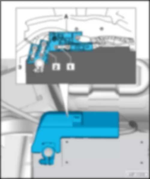
| No. | | Current Flow Diagram designation | Nominal value | | Function/component | Terminal |
| 1 | - | Fuse 1 on fuse holder F -SF1- | 40 A | - | Adaptive suspension compressor relay -J403- | 30 |
| 2 | - | Fuse 2 on fuse holder F -SF2- | 40 A | - | Voltage stabilizer -J532- | 30 |
| 3 | - | Fuse 3 on fuse holder F -SF3- | 40 A | - | Heated rear window relay -J9- | 30 |
| 4 | - | Fuse 4 on fuse holder F -SF4- | 40 A | - | Voltage stabilizer -J532- | 30 |
| 5 | - | Fuse 5 on fuse holder F -SF5- | 35 A | - | All-wheel drive control unit -J492- | 30 |
| 6 | - | Fuse 6 on fuse holder F -SF6- | 30 A
25 A 2) | - | Control unit for reducing agent metering system -J880-1)
Fuel pump relay -J17-2) | 30 |


 Deutsch
 English
 English
 Español
 Français
 Nederlands

