AUTOMOTIVE ELECTRICIANS PORTAL

AUDI Q5 2009 — Body electrical . Wiring diagrams, Pin Connector, Location

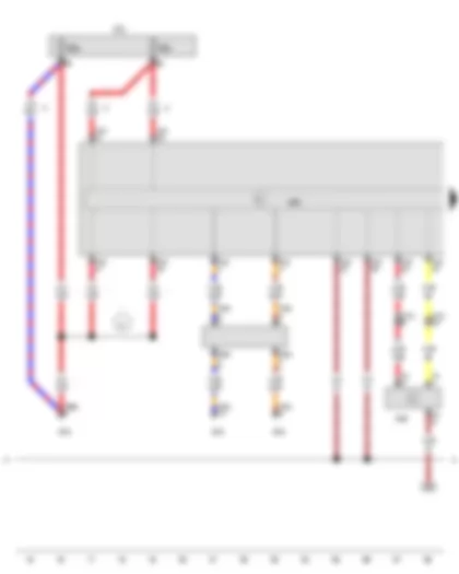
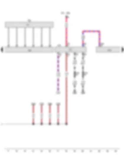
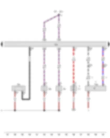
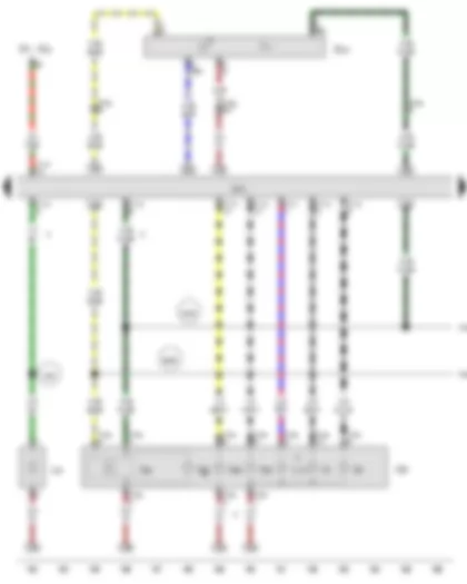
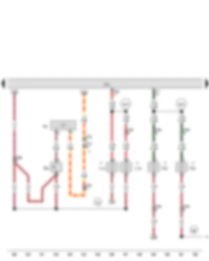
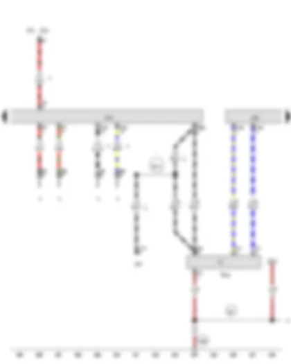
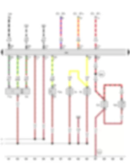
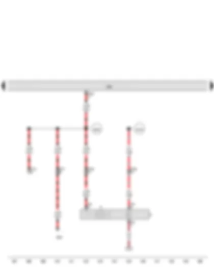
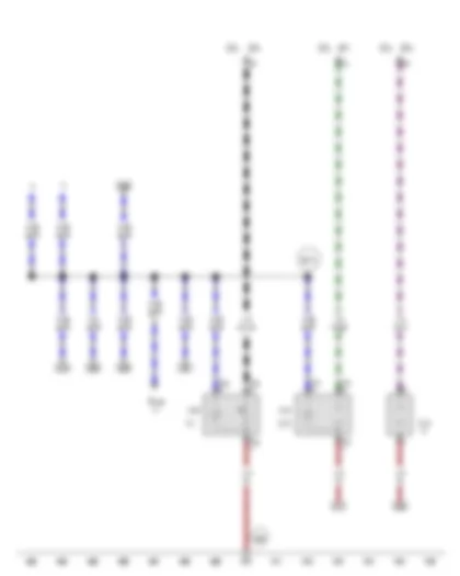
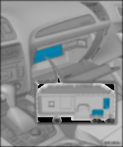
Wiring Diagram AUDI Q5 2009 - Entry and start authorisation switch - Fuse 6 on fuse holder D


Wiring Diagram  AUDI Q5 2009 - Entry and start authorisation switch - Fuse 6 on fuse holder D https://portal-diagnostov.com/license.html
https://portal-diagnostov.com/license.html Automotive Electricians Portal FZCO Automotive Electricians Portal FZCO
Download PDF file
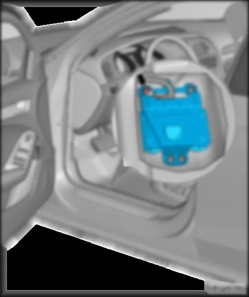
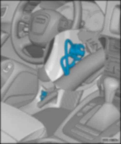
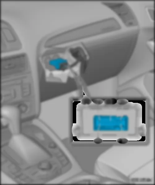
E415 Entry and start authorisation switch
ST2 Fuse carrier 2
SD6 Fuse 6 on fuse holder D
T16g 16-pin connector
T17g 17-pin connector, in right A-pillar coupling station
   135 Earth connection 2, in dash panel wiring harness
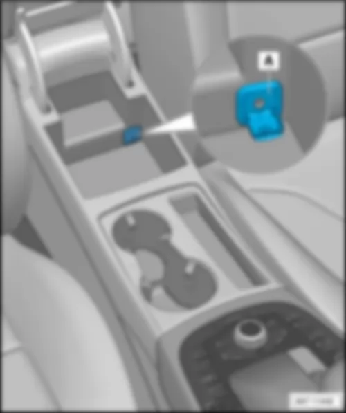
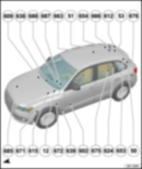
   687 Earth point 1, on centre tunnel
   A209 Connection 1 (LIN bus) in dash panel wiring harness

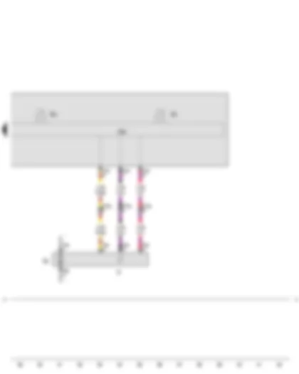
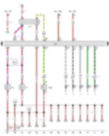
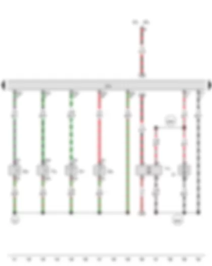
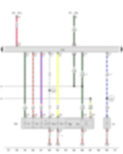
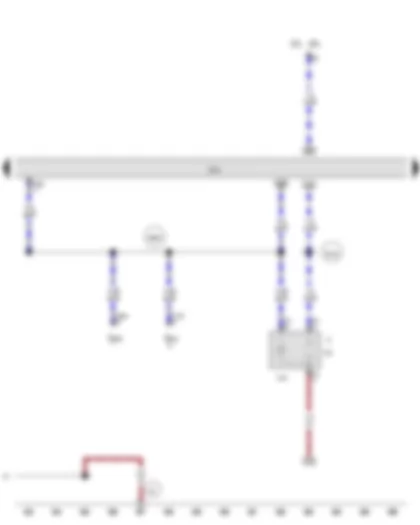
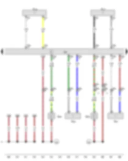
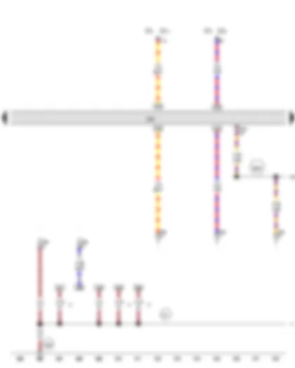
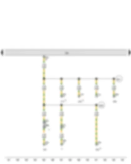
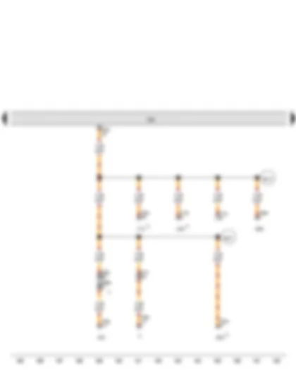
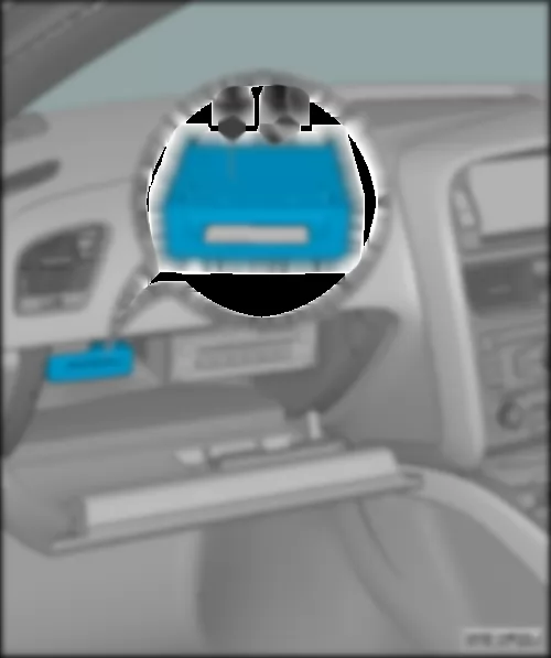
Wiring Diagram AUDI Q5 2009 - Control unit in dash panel insert - Radio controlled clock receiver


Wiring Diagram  AUDI Q5 2009 - Control unit in dash panel insert - Radio controlled clock receiver https://portal-diagnostov.com/license.html
https://portal-diagnostov.com/license.html Automotive Electricians Portal FZCO Automotive Electricians Portal FZCO
Получить доступ ко всем электросхемам автомобиляDownload PDF file
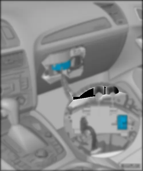
J285 Control unit in dash panel insert
J489 Radio controlled clock receiver
J533 Data bus diagnostic interface
ST2 Fuse carrier 2
SD4 Fuse 4 on fuse holder D
SD5 Fuse 5 on fuse holder D
T3i 3-pin connector
T17c 17-pin connector, in left A-pillar coupling station
T20d 20-pin connector
T32f 32-pin connector
T46s 46-pin connector
   135 Earth connection 2, in dash panel wiring harness
   A1 Positive connection (30a), in dash panel wiring harness
*Up to April 2009
*2From May 2009

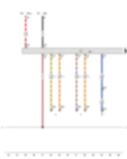
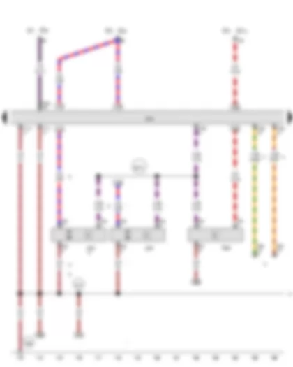
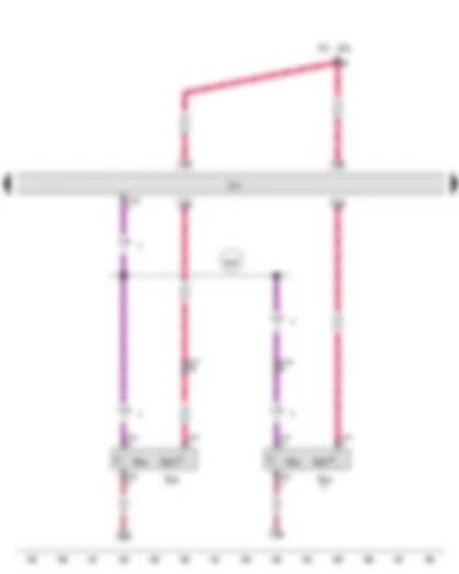
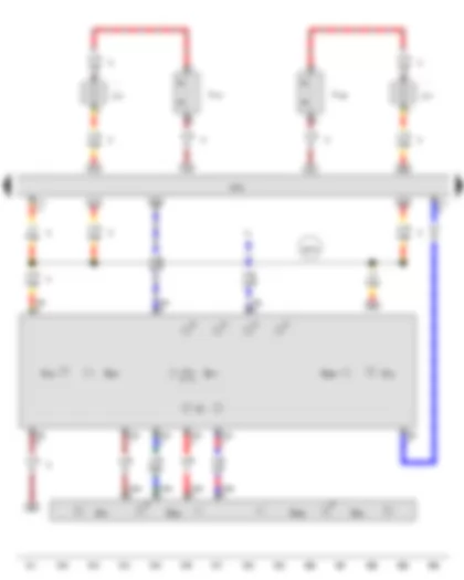
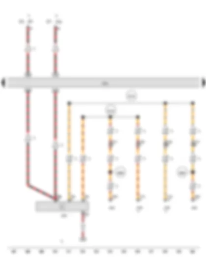
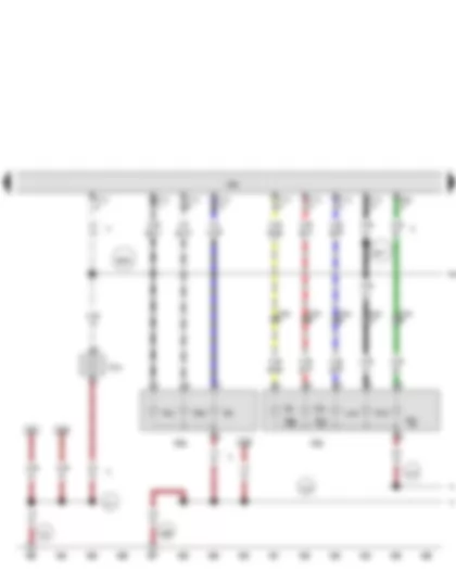
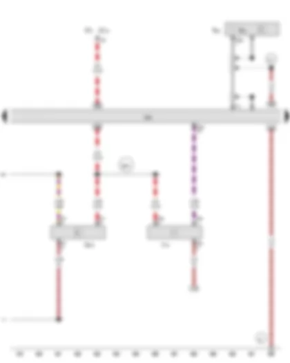
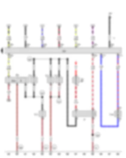
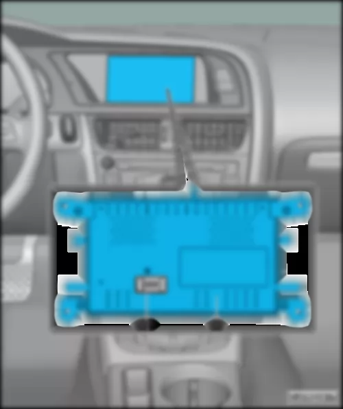
Wiring Diagram AUDI Q5 2009 - Fuel gauge sender - Fuel system pressurisation pump - Control unit in dash panel insert


Wiring Diagram  AUDI Q5 2009 - Fuel gauge sender - Fuel system pressurisation pump - Control unit in dash panel insert https://portal-diagnostov.com/license.html
https://portal-diagnostov.com/license.html Automotive Electricians Portal FZCO Automotive Electricians Portal FZCO
Получить доступ ко всем электросхемам автомобиляDownload PDF file
G Fuel gauge sender
G5 Rev. counter
G6 Fuel system pressurisation pump
G21 Speedometer
J285 Control unit in dash panel insert
T5e 5-pin connector
T17g 17-pin connector, in right A-pillar coupling station
T32f 32-pin connector
   135 Earth connection 2, in dash panel wiring harness
*see applicable current flow diagram for engine

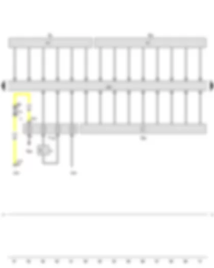
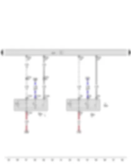
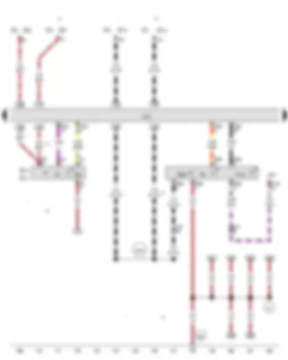
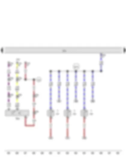
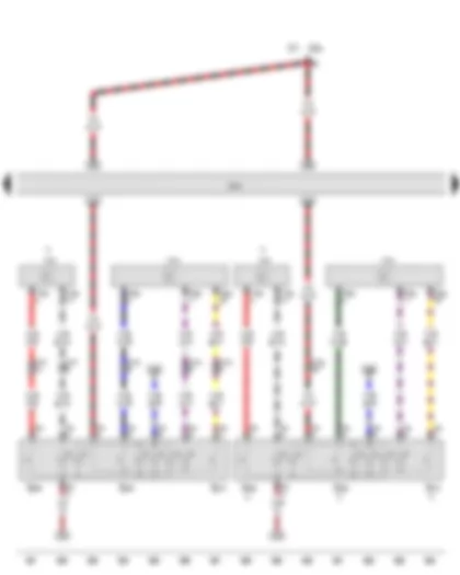
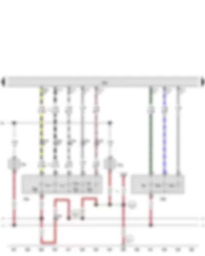
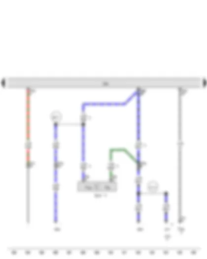
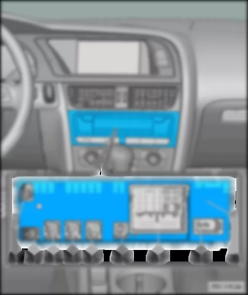
Wiring Diagram AUDI Q5 2009 - Steering column electronics control unit


Wiring Diagram  AUDI Q5 2009 - Steering column electronics control unit https://portal-diagnostov.com/license.html
https://portal-diagnostov.com/license.html Automotive Electricians Portal FZCO Automotive Electricians Portal FZCO
Получить доступ ко всем электросхемам автомобиляDownload PDF file
J527 Steering column electronics control unit
ST1 Fuse carrier 1
ST2 Fuse carrier 2
SD5 Fuse 5 on fuse holder D
SD12 Fuse 12 on fuse holder D
T16f 16-pin connector
T17b 17-pin connector, in left A-pillar coupling station
T17q 17-pin connector, in E-box
T46s 46-pin connector
   135 Earth connection 2, in dash panel wiring harness
*see applicable current flow diagram for engine
*2Front passenger side push-in bridge, brown
*3Data bus wire (CAN bus)

Wiring Diagram AUDI Q5 2009 - Turn signal switch - Cruise control system switch - Steering column electronics control unit


Wiring Diagram  AUDI Q5 2009 - Turn signal switch - Cruise control system switch - Steering column electronics control unit https://portal-diagnostov.com/license.html
https://portal-diagnostov.com/license.html Automotive Electricians Portal FZCO Automotive Electricians Portal FZCO
Получить доступ ко всем электросхемам автомобиляDownload PDF file
E2 Turn signal switch
E45 Cruise control system switch
F138 Airbag coil connector and return ring with slip ring
G85 Steering angle sender
H Horn plate
J234 Airbag control unit
J453 Multifunction steering wheel control unit
J527 Steering column electronics control unit
N95 Driver side airbag igniter
T4ac 4-pin connector
T5b 5-pin connector
T17x 17-pin connector
T100 100-pin connector
   135 Earth connection 2, in dash panel wiring harness
*Up to April 2009
*2From May 2009

Wiring Diagram AUDI Q5 2009 - Intermittent wiper switch - Steering column electronics control unit - Control unit for electronic steering column lock


Wiring Diagram  AUDI Q5 2009 - Intermittent wiper switch - Steering column electronics control unit - Control unit for electronic steering column lock https://portal-diagnostov.com/license.html
https://portal-diagnostov.com/license.html Automotive Electricians Portal FZCO Automotive Electricians Portal FZCO
Получить доступ ко всем электросхемам автомобиляDownload PDF file
E22 Intermittent wiper switch
J519 Onboard supply control unit
J527 Steering column electronics control unit
J764 Control unit for electronic steering column lock
ST2 Fuse carrier 2
SD9 Fuse 9 on fuse holder D
T6z 6-pin connector
T17e 17-pin connector, in left A-pillar coupling station
T17g 17-pin connector, in right A-pillar coupling station
T32a 32-pin connector
   135 Earth connection 2, in dash panel wiring harness
*Cross section depends on equipment
Wiring Diagram AUDI Q5 2009 - Start/Stop operation button


Wiring Diagram  AUDI Q5 2009 - Start/Stop operation button https://portal-diagnostov.com/license.html
https://portal-diagnostov.com/license.html Automotive Electricians Portal FZCO Automotive Electricians Portal FZCO
Получить доступ ко всем электросхемам автомобиляDownload PDF file
E656 Button for electric drive
E693 Start/Stop operation button
J519 Onboard supply control unit
T8s 8-pin connector
T12ab 12-pin connector
T17b 17-pin connector, in left A-pillar coupling station
T32a 32-pin connector
*Only models with stop/start system
*2Only models with no hybrid drive system
*3Gradually discontinued
*4Only models with hybrid drive system

Wiring Diagram AUDI Q5 2009 - Bonnet contact switch - Treble horn - Bass horn - Horn relay


Wiring Diagram  AUDI Q5 2009 - Bonnet contact switch - Treble horn - Bass horn - Horn relay https://portal-diagnostov.com/license.html
https://portal-diagnostov.com/license.html Automotive Electricians Portal FZCO Automotive Electricians Portal FZCO
Получить доступ ко всем электросхемам автомобиляDownload PDF file
F266 Bonnet contact switch
H2 Treble horn
H7 Bass horn
J413 Horn relay
J519 Onboard supply control unit
ST2 Fuse carrier 2
ST3 Fuse carrier 3
SC6 Fuse 6 on fuse holder C
SC7 Fuse 7 on fuse holder C
T2s 2-pin connector
T17l 17-pin connector
T17q 17-pin connector, in E-box
T17r 17-pin connector, in E-box
T32b 32-pin connector
   366 Earth connection 1, in main wiring harness
   368 Earth connection 3, in main wiring harness
   638 Earth point, on right A-pillar
   639 Earth point, left A-pillar
   B474 Connection 10, in main wiring harness
*Gradually discontinued
*2see applicable current flow diagram for engine
*3Wiring colour depends on equipment
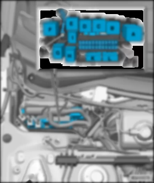
*4Cross section depends on equipment
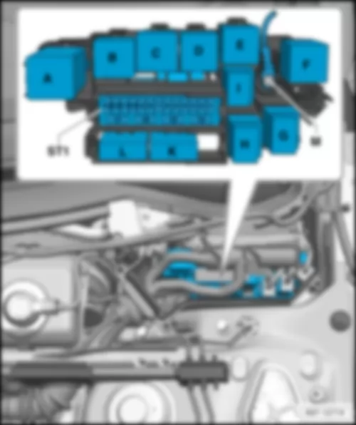
*5gradual introduction

Wiring Diagram AUDI Q5 2009 - Rain and light sensor - Wiper motor control unit


Wiring Diagram  AUDI Q5 2009 - Rain and light sensor - Wiper motor control unit https://portal-diagnostov.com/license.html
https://portal-diagnostov.com/license.html Automotive Electricians Portal FZCO Automotive Electricians Portal FZCO
Получить доступ ко всем электросхемам автомобиляDownload PDF file
G397 Rain and light sensor
J400 Wiper motor control unit
J519 Onboard supply control unit
ST1 Fuse carrier 1
ST2 Fuse carrier 2
SC8 Fuse 8 on fuse holder C
SC9 Fuse 9 on fuse holder C
SC12 Fuse 12 on fuse holder C
T3c 3-pin connector
T4g 4-pin connector
T16b 16-pin connector
T17m 17-pin connector
T17n 17-pin connector
T32b 32-pin connector
T46i 46-pin connector
   370 Earth connection 5, in main wiring harness
   639 Earth point, left A-pillar
   B475 Connection 11, in main wiring harness
*Only right-hand drive models
*2Left-hand drive models
*3Driver side push-in bridge, brown
*4Data bus wire (CAN bus)

Wiring Diagram AUDI Q5 2009 - Gear detector switch - Front left brake pad wear sender - Headlight washer system pump - Left washer jet heater element - Right washer jet heater element


Wiring Diagram  AUDI Q5 2009 - Gear detector switch - Front left brake pad wear sender - Headlight washer system pump - Left washer jet heater element - Right washer jet heater element https://portal-diagnostov.com/license.html
https://portal-diagnostov.com/license.html Automotive Electricians Portal FZCO Automotive Electricians Portal FZCO
Получить доступ ко всем электросхемам автомобиляDownload PDF file
F208 Gear detector switch
G34 Front left brake pad wear sender
J519 Onboard supply control unit
ST1 Fuse carrier 1
SC11 Fuse 11 on fuse holder C
T2b 2-pin connector
T2i 2-pin connector
T2r 2-pin connector
T2v 2-pin connector
T17l 17-pin connector
T17q 17-pin connector, in E-box
T32b 32-pin connector
V11 Headlight washer system pump
Z20 Left washer jet heater element
Z21 Right washer jet heater element
   370 Earth connection 5, in main wiring harness
*Only models with heater elements for washer jets
*2Only models with headlight washer system
*3see applicable current flow diagram for engine

Wiring Diagram AUDI Q5 2009 - Brake fluid level warning contact - Ambient temperature sensor - Coolant shortage indicator sender - Windscreen washer fluid level sender - Rear window wiper motor


Wiring Diagram  AUDI Q5 2009 - Brake fluid level warning contact - Ambient temperature sensor - Coolant shortage indicator sender - Windscreen washer fluid level sender - Rear window wiper motor https://portal-diagnostov.com/license.html
https://portal-diagnostov.com/license.html Automotive Electricians Portal FZCO Automotive Electricians Portal FZCO
Получить доступ ко всем электросхемам автомобиляDownload PDF file
F34 Brake fluid level warning contact
G17 Ambient temperature sensor
G32 Coolant shortage indicator sender
G33 Windscreen washer fluid level sender
J519 Onboard supply control unit
ST4 Fuse carrier 4
SF8 Fuse 8 in fuse holder F
T2a 2-pin connector
T2aa 2-pin connector
T2t 2-pin connector
T2u 2-pin connector
T17l 17-pin connector
T32b 32-pin connector
V5 Washer pump
V12 Rear window wiper motor
   401 Earth connection (sender earth), in interior wiring harness
   B536 Connection 27, in main wiring harness
   B538 Connection 29, in main wiring harness
*Cross section depends on equipment
Wiring Diagram AUDI Q5 2009 - Switch module for driving mode selection


Wiring Diagram  AUDI Q5 2009 - Switch module for driving mode selection https://portal-diagnostov.com/license.html
https://portal-diagnostov.com/license.html Automotive Electricians Portal FZCO Automotive Electricians Portal FZCO
Получить доступ ко всем электросхемам автомобиляDownload PDF file
E592 Switch module for driving mode selection
E593 Button 1 in switch module for driving mode selection
E594 Button 2 in switch module for driving mode selection
J519 Onboard supply control unit
SD2 Fuse 2 on fuse holder D
ST2 Fuse carrier 2
T3m 3-pin connector
T16b 16-pin connector
T17d 17-pin connector, in left A-pillar coupling station
T17f 17-pin connector, in right A-pillar coupling station
   B549 Connection 2 (LIN bus) in main wiring harness
*Only models with no navigation system
*2Only models with navigation system
*3Wiring colour depends on equipment

Wiring Diagram AUDI Q5 2009 - Light switch - Hazard warning lights button


Wiring Diagram  AUDI Q5 2009 - Light switch - Hazard warning lights button https://portal-diagnostov.com/license.html
https://portal-diagnostov.com/license.html Automotive Electricians Portal FZCO Automotive Electricians Portal FZCO
Получить доступ ко всем электросхемам автомобиляDownload PDF file
E1 Light switch
E20 Switch and instrument illumination regulator
E229 Hazard warning lights button
E314 Rear fog light button
E315 Fog light button
J234 Airbag control unit
J519 Onboard supply control unit
K6 Indicator lamp for hazard warning light
K145 Front passenger side airbag deactivated warning lamp
ST1 Fuse carrier 1
ST2 Fuse carrier 2
SD4 Fuse 4 on fuse holder D
ST4 Fuse carrier 4
SD7 Fuse 7 on fuse holder D
SF12 Fuse 12 in fuse holder F
SC14 Fuse 14 on fuse holder C
T4t 4-pin connector
T6ae 6-pin connector
T17f 17-pin connector, in right A-pillar coupling station
T32a 32-pin connector
T100 100-pin connector
   81 Earth connection 1, in dash panel wiring harness
   687 Earth point 1, on centre tunnel
   B163 Positive connection 1 (15), in interior wiring harness
*Up to April 2009
*2From May 2009

Wiring Diagram AUDI Q5 2009 - Front left headlight


Wiring Diagram  AUDI Q5 2009 - Front left headlight https://portal-diagnostov.com/license.html
https://portal-diagnostov.com/license.html Automotive Electricians Portal FZCO Automotive Electricians Portal FZCO
Получить доступ ко всем электросхемам автомобиляDownload PDF file
E102 Headlight range control regulator
J519 Onboard supply control unit
L22 Left fog light bulb
L174 Left daytime running light bulb
M1 Left side light bulb
MX1 Front left headlight
M5 Front left turn signal bulb
M29 Left headlight dipped beam bulb
M30 Left headlight main beam bulb
M33 Front left side marker bulb
ST3 Fuse carrier 3
SC8 Fuse 8 on fuse holder C
T10a 10-pin connector
T17b 17-pin connector, in left A-pillar coupling station
T17g 17-pin connector, in right A-pillar coupling station
T17m 17-pin connector
T17n 17-pin connector
V48 Left headlight range control motor
   B165 Positive connection 2 (15), in interior wiring harness
   B488 Connection 24, in main wiring harness
   C69 Front left connection (fog light),, in main wiring harness
*Only models with no US equipment
*2Only models with US equipment
*3Only models with daytime running lights
*4Cross section depends on equipment

Wiring Diagram AUDI Q5 2009 - Front right headlight


Wiring Diagram  AUDI Q5 2009 - Front right headlight https://portal-diagnostov.com/license.html
https://portal-diagnostov.com/license.html Automotive Electricians Portal FZCO Automotive Electricians Portal FZCO
Получить доступ ко всем электросхемам автомобиляDownload PDF file
J519 Onboard supply control unit
L23 Right fog light bulb
L175 Right daytime running light bulb
MX2 Front right headlight
M3 Right side light bulb
M7 Front right turn signal bulb
M31 Right headlight dipped beam bulb
M32 Right headlight main beam bulb
M34 Front right side marker bulb
ST1 Fuse carrier 1
ST3 Fuse carrier 3
SC6 Fuse 6 on fuse holder C
SC10 Fuse 10 on fuse holder C
T10b 10-pin connector
T17m 17-pin connector
T17n 17-pin connector
V49 Right headlight range control motor
   B165 Positive connection 2 (15), in interior wiring harness
   B488 Connection 24, in main wiring harness
   C15 Connection 1, in headlight wiring harness
   C25 Connection (fog light), in front lighting wiring harness
*Only models with no US equipment
*2Only models with daytime running lights
*3Only models with US equipment
*4Cross section depends on equipment

Wiring Diagram AUDI Q5 2009 - Rear left reading light button - Vanity mirror light bulb - Front interior light - Rear right interior light


Wiring Diagram  AUDI Q5 2009 - Rear left reading light button - Vanity mirror light bulb - Front interior light - Rear right interior light https://portal-diagnostov.com/license.html
https://portal-diagnostov.com/license.html Automotive Electricians Portal FZCO Automotive Electricians Portal FZCO
Получить доступ ко всем электросхемам автомобиляDownload PDF file
E317 Interior light switch
E454 Rear left reading light button
E455 Rear right reading light button
E457 Driver side reading light button
E458 Front passenger side reading light button
F147 Driver vanity mirror contact switch
F148 Front passenger vanity mirror contact switch
J519 Onboard supply control unit
L31 Vanity mirror light bulb
T4ar 4-pin connector
T4as 4-pin connector
T8b 8-pin connector
T17l 17-pin connector
W1 Front interior light
W13 Front passenger reading light
W19 Driver side reading light
W47 Rear left interior light
W48 Rear right interior light
Y7 Automatic anti-dazzle interior mirror
   B476 Connection 12, in main wiring harness
*According to equipment
*2Cross section depends on equipment

Wiring Diagram AUDI Q5 2009 - Key operated switch to deactivate front passenger side airbag


Wiring Diagram  AUDI Q5 2009 - Key operated switch to deactivate front passenger side airbag https://portal-diagnostov.com/license.html
https://portal-diagnostov.com/license.html Automotive Electricians Portal FZCO Automotive Electricians Portal FZCO
Получить доступ ко всем электросхемам автомобиляDownload PDF file
E224 Key operated switch to deactivate front passenger side airbag
J234 Airbag control unit
J519 Onboard supply control unit
L67 Dash panel left vent illumination bulb
L68 Dash panel central vent illumination
L69 Dash panel right vent illumination bulb
T12k 12-pin connector
T17g 17-pin connector, in right A-pillar coupling station
T32a 32-pin connector
T100 100-pin connector
   475 Earth connection (airbag), in main wiring harness
   B478 Connection 14, in main wiring harness
*Only models with key operated switch to deactivate front passenger airbag
*2According to equipment

Wiring Diagram AUDI Q5 2009 - Glove compartment light switch - Front left footwell illumination bulb - Front right footwell illumination bulb - Glove compartment light


Wiring Diagram  AUDI Q5 2009 - Glove compartment light switch - Front left footwell illumination bulb - Front right footwell illumination bulb - Glove compartment light https://portal-diagnostov.com/license.html
https://portal-diagnostov.com/license.html Automotive Electricians Portal FZCO Automotive Electricians Portal FZCO
Получить доступ ко всем электросхемам автомобиляDownload PDF file
E26 Glove compartment light switch
J519 Onboard supply control unit
L151 Front left footwell illumination bulb
L152 Front right footwell illumination bulb
T10m 10-pin connector, Coupling point under front passenger seat
T10p 10-pin connector, near driver seat
T12k 12-pin connector
T17d 17-pin connector, brown
T17g 17-pin connector, black
T17l 17-pin connector
T32a 32-pin connector
W6 Glove compartment light
W45 Rear left footwell light
W46 Rear right footwell light
   369 Earth connection 4, in main wiring harness
   378 Earth connection 13, in main wiring harness
   B433 Connection (footwell light), in main wiring harness
   B479 Connection 15, in main wiring harness
*Gradually discontinued
*2According to equipment
*3gradual introduction

Wiring Diagram AUDI Q5 2009 - 12 V socket


Wiring Diagram  AUDI Q5 2009 - 12 V socket https://portal-diagnostov.com/license.html
https://portal-diagnostov.com/license.html Automotive Electricians Portal FZCO Automotive Electricians Portal FZCO
Получить доступ ко всем электросхемам автомобиляDownload PDF file
E540 Auto-hold button
G538 Potentiometer for rear temperature selection
J519 Onboard supply control unit
L42 Socket illumination bulb
SF2 Fuse 2 in fuse holder F
ST4 Fuse carrier 4
T3l 3-pin connector
T8ad 8-pin connector
T12b 12-pin connector
T32b 32-pin connector
U5 12 V socket, in front centre console
   51 Earth point, on right in luggage compartment
   369 Earth connection 4, in main wiring harness
   B149 Positive connection 2 (15a), in interior wiring harness
   B490 Connection 26, in main wiring harness
*see applicable current flow diagram for air conditioning
*2According to equipment

Wiring Diagram AUDI Q5 2009 - Adaptive cruise control unit


Wiring Diagram  AUDI Q5 2009 - Adaptive cruise control unit https://portal-diagnostov.com/license.html
https://portal-diagnostov.com/license.html Automotive Electricians Portal FZCO Automotive Electricians Portal FZCO
Получить доступ ко всем электросхемам автомобиляDownload PDF file
J428 Adaptive cruise control unit
J519 Onboard supply control unit
J533 Data bus diagnostic interface
J769 Lane change assist control unit
ST1 Fuse carrier 1
ST4 Fuse carrier 4
SF7 Fuse 7 in fuse holder F
SC9 Fuse 9 on fuse holder C
T8a 8-pin connector
T12f 12-pin connector
T12h 12-pin connector
T17f 17-pin connector, in right A-pillar coupling station
T20d 20-pin connector
   B108 Connection 1 (CAN bus extended high), in main wiring harness
   B109 Connection 1 (CAN bus extended low), in main wiring harness
   B665 Connection 1 (CAN bus extended high), in dash panel wiring harness
   B666 Connection 1 (CAN bus extended low), in dash panel wiring harness
*Only models with adaptive cruise control (ACC)
*2From May 2009
*3Up to April 2009
*4Only models with lane departure warning assist
*5Data bus wire (CAN bus)

Wiring Diagram AUDI Q5 2009 - TCS and ESP button - Parking aid button - Hill descent control button


Wiring Diagram  AUDI Q5 2009 - TCS and ESP button - Parking aid button - Hill descent control button https://portal-diagnostov.com/license.html
https://portal-diagnostov.com/license.html Automotive Electricians Portal FZCO Automotive Electricians Portal FZCO
Получить доступ ко всем электросхемам автомобиляDownload PDF file
E256 TCS and ESP button
E266 Parking aid button
E618 Hill descent control button
J104 ABS control unit
J519 Onboard supply control unit
J791 Park assist steering control unit
ST1 Fuse carrier 1
SD6 Fuse 6 on fuse holder D
T8r 8-pin connector
T16e 16-pin connector
T17c 17-pin connector, in left A-pillar coupling station
T17f 17-pin connector, in right A-pillar coupling station
T17g 17-pin connector, in right A-pillar coupling station
T38a 38-pin connector
*Only models with navigation system
*2Only models with no navigation system
*3Only models with parking aid (PDC)

Wiring Diagram AUDI Q5 2009 - Entry and start authorisation button - Convenience system central control unit


Wiring Diagram  AUDI Q5 2009 - Entry and start authorisation button - Convenience system central control unit https://portal-diagnostov.com/license.html
https://portal-diagnostov.com/license.html Automotive Electricians Portal FZCO Automotive Electricians Portal FZCO
Получить доступ ко всем электросхемам автомобиляDownload PDF file
E408 Entry and start authorisation button
J393 Convenience system central control unit
J519 Onboard supply control unit
J587 Selector lever sensors control unit
ST2 Fuse carrier 2
SC5 Fuse 5 on fuse holder C
T4n 4-pin connector
T6f 6-pin connector
T6k 6-pin connector, Coupling point under front passenger seat
T6l 6-pin connector, near driver seat
T10k 10-pin connector
T32b 32-pin connector
T32e 32-pin connector
   367 Earth connection 2, in main wiring harness
   688 Earth point 2, on centre tunnel
   B472 Connection 8, in main wiring harness
*Only models with automatic gearbox
*2see applicable current flow diagram for seat heating
*3Cross section depends on equipment

Wiring Diagram AUDI Q5 2009 - Contact sensor for front left exterior door handle - Contact sensor for front right exterior door handle - Convenience system central control unit - Left aerial for entry and start authorisation


Wiring Diagram  AUDI Q5 2009 - Contact sensor for front left exterior door handle - Contact sensor for front right exterior door handle - Convenience system central control unit - Left aerial for entry and start authorisation https://portal-diagnostov.com/license.html
https://portal-diagnostov.com/license.html Automotive Electricians Portal FZCO Automotive Electricians Portal FZCO
Получить доступ ко всем электросхемам автомобиляDownload PDF file
G605 Contact sensor for front left exterior door handle
G606 Contact sensor for front right exterior door handle
J393 Convenience system central control unit
R137 Luggage compartment aerial for entry and start system
R138 Interior aerial 1 for entry and start system
R200 Left aerial for entry and start authorisation
R201 Right aerial for entry and start authorisation
T2aj 2-pin connector
T2bv 2-pin connector
T20m 20-pin connector, on right A-pillar
T27a 27-pin connector, on left A-pillar
T27b 27-pin connector, on left B-pillar
T27c 27-pin connector, on right A-pillar
T27d 27-pin connector, on right B-pillar
T32e 32-pin connector
   205 Earth connection, in driver door wiring harness
   206 Earth connection, in front passenger door wiring harness
   367 Earth connection 2, in main wiring harness
*Gradually discontinued
*2gradual introduction

Wiring Diagram AUDI Q5 2009 - Convenience system central control unit - Left tail light - Left tail light 2 - Luggage compartment light on left


Wiring Diagram  AUDI Q5 2009 - Convenience system central control unit - Left tail light - Left tail light 2 - Luggage compartment light on left https://portal-diagnostov.com/license.html
https://portal-diagnostov.com/license.html Automotive Electricians Portal FZCO Automotive Electricians Portal FZCO
Получить доступ ко всем электросхемам автомобиляDownload PDF file
J393 Convenience system central control unit
L46 Rear left fog light bulb
MX3 Left tail light
MX5 Left tail light 2
M6 Rear left turn signal bulb
M16 Left reversing light bulb
M21 Left brake and tail light bulb
M37 Rear left side marker bulb
M58 Left brake and tail light bulb 2
M69 Left brake, turn signal and tail light bulb
M72 Bulb 2 for left brake, turn signal and tail light
T12v 12-pin connector, in rear bumper
T17o 17-pin connector
T17p 17-pin connector
T32c 32-pin connector
W18 Luggage compartment light on left
   50 Earth point, on left in luggage compartment
   218 Earth connection 1, in rear lid wiring harness
   371 Earth connection 6, in main wiring harness
   470 Earth connection 1, in rear bumper wiring harness
   666 Earth point, on rear right of roof
   B477 Connection 13, in main wiring harness
   B539 Connection 30, in main wiring harness
*Only models with no US equipment
*2Only models with US equipment
*3Cross section depends on equipment

Wiring Diagram AUDI Q5 2009 - Convenience system central control unit - Right tail light - Right luggage compartment light - Surround lighting 1 in rear lid


Wiring Diagram  AUDI Q5 2009 - Convenience system central control unit - Right tail light - Right luggage compartment light - Surround lighting 1 in rear lid https://portal-diagnostov.com/license.html
https://portal-diagnostov.com/license.html Automotive Electricians Portal FZCO Automotive Electricians Portal FZCO
Получить доступ ко всем электросхемам автомобиляDownload PDF file
J393 Convenience system central control unit
L47 Rear right fog light bulb
MX4 Right tail light
MX6 Right tail light 2
M8 Rear right turn signal bulb
M17 Right reversing light bulb
M22 Right brake and tail light bulb
M38 Rear right side marker bulb
M59 Right brake and tail light bulb 2
M70 Right brake, turn signal and tail light bulb
M73 Bulb 2 for right brake, turn signal and tail light
T12v 12-pin connector, in rear bumper
T17o 17-pin connector
T17p 17-pin connector
T32c 32-pin connector
W35 Right luggage compartment light
W61 Surround lighting 1 in rear lid
   51 Earth point, on right in luggage compartment
   218 Earth connection 1, in rear lid wiring harness
   372 Earth connection 7, in main wiring harness
   381 Earth connection 16, in main wiring harness
   470 Earth connection 1, in rear bumper wiring harness
   B539 Connection 30, in main wiring harness
*Only models with no US equipment
*2Only models with US equipment
*3Cross section depends on equipment

Wiring Diagram AUDI Q5 2009 - Convenience system central control unit - Rear lid central locking motor


Wiring Diagram  AUDI Q5 2009 - Convenience system central control unit - Rear lid central locking motor https://portal-diagnostov.com/license.html
https://portal-diagnostov.com/license.html Automotive Electricians Portal FZCO Automotive Electricians Portal FZCO
Получить доступ ко всем электросхемам автомобиляDownload PDF file
C24 Suppression filter
F124 Contact switch in lock cylinder for rear lid, anti-theft alarm system and central locking system
F248 Release button for rear lid lock cylinder
J329 Terminal 15 voltage supply relay
J393 Convenience system central control unit
M25 Additional brake light bulb
ST2 Fuse carrier 2
SF8 Fuse 8 in fuse holder F
SF10 Fuse 10 in fuse holder F
SF11 Fuse 11 in fuse holder F
T2g 2-pin connector
T17o 17-pin connector
T17p 17-pin connector
T32c 32-pin connector
T32d 32-pin connector
V53 Rear lid central locking motor
X4 Left number plate light
X5 Right number plate light
   218 Earth connection 1, in rear lid wiring harness
   381 Earth connection 16, in main wiring harness
   612 Earth point, centre on rear lid
   B564 Connection 31, in main wiring harness
*Cross section depends on equipment

Wiring Diagram AUDI Q5 2009 - Convenience system central control unit


Wiring Diagram  AUDI Q5 2009 - Convenience system central control unit https://portal-diagnostov.com/license.html
https://portal-diagnostov.com/license.html Automotive Electricians Portal FZCO Automotive Electricians Portal FZCO
Получить доступ ко всем электросхемам автомобиляDownload PDF file
J393 Convenience system central control unit
ST3 Fuse carrier 3
SC9 Fuse 9 on fuse holder C
SC11 Fuse 11 on fuse holder C
T6e 6-pin connector, black
T32c 32-pin connector
   277 Earth connection 3, in interior wiring harness
   639 Earth point, left A-pillar
   B528 Connection 1 (LIN bus) in main wiring harness
*Only models with panoramic sliding sunroof
*2Cross section depends on equipment

Wiring Diagram AUDI Q5 2009 - Anti-theft alarm sensor - Alarm horn - Convenience system central control unit - Central locking and anti-theft alarm system aerial


Wiring Diagram  AUDI Q5 2009 - Anti-theft alarm sensor - Alarm horn - Convenience system central control unit - Central locking and anti-theft alarm system aerial https://portal-diagnostov.com/license.html
https://portal-diagnostov.com/license.html Automotive Electricians Portal FZCO Automotive Electricians Portal FZCO
Получить доступ ко всем электросхемам автомобиляDownload PDF file
G578 Anti-theft alarm sensor
H12 Alarm horn
J393 Convenience system central control unit
R24 Aerial amplifier
R47 Central locking and anti-theft alarm system aerial
ST3 Fuse carrier 3
SC12 Fuse 12 on fuse holder C
T1h Single connector
T2de 2-pin connector
T3e 3-pin connector
T4f 4-pin connector
T32c 32-pin connector
   51 Earth point, on right in luggage compartment
   277 Earth connection 3, in interior wiring harness
   377 Earth connection 12, in main wiring harness
   B301 Positive connection 5 (30), in main wiring harness
   B528 Connection 1 (LIN bus) in main wiring harness

Wiring Diagram AUDI Q5 2009 - Clutch pedal switch - Convenience system central control unit


Wiring Diagram  AUDI Q5 2009 - Clutch pedal switch - Convenience system central control unit https://portal-diagnostov.com/license.html
https://portal-diagnostov.com/license.html Automotive Electricians Portal FZCO Automotive Electricians Portal FZCO
Получить доступ ко всем электросхемам автомобиляDownload PDF file
F36 Clutch pedal switch
F194 Clutch pedal switch for engine start
F305 Gear selector position P switch
G476 Clutch position sender
J217 Automatic gearbox control unit
J393 Convenience system central control unit
J623 Engine control unit
J743 Mechatronic unit for dual clutch gearbox
T4h 4-pin connector
T6g 6-pin connector
T17q 17-pin connector, in E-box
T17r 17-pin connector, in E-box
T32d 32-pin connector
   B471 Connection 7, in main wiring harness
   D114 Connection 12 in engine compartment wiring harness
*see applicable current flow diagram for engine
*2Only models with manual gearbox
*3see applicable current flow diagram for automatic gearbox

Wiring Diagram AUDI Q5 2009 - Brake light switch - Convenience system central control unit


Wiring Diagram  AUDI Q5 2009 - Brake light switch - Convenience system central control unit https://portal-diagnostov.com/license.html
https://portal-diagnostov.com/license.html Automotive Electricians Portal FZCO Automotive Electricians Portal FZCO
Получить доступ ко всем электросхемам автомобиляDownload PDF file
F Brake light switch
J393 Convenience system central control unit
J623 Engine control unit
T4k 4-pin connector
T12u 12-pin connector, brown
T17e 17-pin connector, in left A-pillar coupling station
T17r 17-pin connector, in E-box
T32d 32-pin connector
   B146 Positive connection 1 (87), in interior wiring harness
   B335 Connection 1 (54), in main wiring harness
*see applicable current flow diagram for engine
*2Solenoid coil for brake light sensor

Wiring Diagram AUDI Q5 2009 - Convenience system central control unit


Wiring Diagram  AUDI Q5 2009 - Convenience system central control unit https://portal-diagnostov.com/license.html
https://portal-diagnostov.com/license.html Automotive Electricians Portal FZCO Automotive Electricians Portal FZCO
Получить доступ ко всем электросхемам автомобиляDownload PDF file
J345 Trailer detector control unit
J387 Front passenger door control unit
J393 Convenience system central control unit
J502 Tyre Pressure Monitoring System control unit
J605 Rear lid control unit
J772 Reversing camera system control unit
T8ae 8-pin connector
T12d 12-pin connector
T12u 12-pin connector, brown
T17f 17-pin connector, in right A-pillar coupling station
T20a 20-pin connector
T20g 20-pin connector
T20m 20-pin connector, in right A-pillar
T27c 27-pin connector, in right A-pillar
T32c 32-pin connector
T46s 46-pin connector
T54b 54-pin connector
   B398 Connection 2 (convenience CAN bus, high), in main wiring harness
   B401 Connection 5 (convenience CAN bus, high), in main wiring harness
*Gradually discontinued
*2According to equipment
*3Front passenger side push-in bridge, brown
*4gradual introduction

Wiring Diagram AUDI Q5 2009 - Convenience system central control unit


Wiring Diagram  AUDI Q5 2009 - Convenience system central control unit https://portal-diagnostov.com/license.html
https://portal-diagnostov.com/license.html Automotive Electricians Portal FZCO Automotive Electricians Portal FZCO
Получить доступ ко всем электросхемам автомобиляDownload PDF file
J345 Trailer detector control unit
J387 Front passenger door control unit
J393 Convenience system central control unit
J502 Tyre Pressure Monitoring System control unit
J605 Rear lid control unit
J772 Reversing camera system control unit
T8ae 8-pin connector
T12d 12-pin connector
T12u 12-pin connector, brown
T17f 17-pin connector, in right A-pillar coupling station
T20a 20-pin connector
T20g 20-pin connector
T20m 20-pin connector, in right A-pillar
T27c 27-pin connector, in right A-pillar
T32c 32-pin connector
T46s 46-pin connector
T54b 54-pin connector
   B407 Connection 2 (convenience CAN bus, low), in main wiring harness
   B410 Connection 5 (convenience CAN bus, low), in main wiring harness
*Gradually discontinued
*2Front passenger side push-in bridge, brown
*3According to equipment
*4gradual introduction

Wiring Diagram AUDI Q5 2009 - Glass breakage sensor for rear window - Convenience system central control unit - Tank filler flap locking motor - Heated rear window


Wiring Diagram  AUDI Q5 2009 - Glass breakage sensor for rear window - Convenience system central control unit - Tank filler flap locking motor - Heated rear window https://portal-diagnostov.com/license.html
https://portal-diagnostov.com/license.html Automotive Electricians Portal FZCO Automotive Electricians Portal FZCO
Получить доступ ко всем электросхемам автомобиляDownload PDF file
C18 Window aerial suppression filter
G304 Glass breakage sensor for rear window
J9 Heated rear window relay
J393 Convenience system central control unit
J807 Relay for power sockets
S41 Heated rear window single fuse
T2k 2-pin connector
T17o 17-pin connector
T32c 32-pin connector
T32d 32-pin connector
V155 Tank filler flap locking motor
Z1 Heated rear window
Z24 Heated rear window with window aerial
   51 Earth point, on right in luggage compartment
   53 Earth point, on right in rear lid
   219 Earth connection 2, in rear lid wiring harness
   249 Earth connection 2, in interior wiring harness
   666 Earth point, on rear right of roof
   Q22 Connection 1, in rear lid wiring harness
   Q44 Connection 2, in rear lid wiring harness
*see applicable current flow diagram for fuse assignment
*2Cross section depends on equipment

Wiring Diagram AUDI Q5 2009 - Cigarette lighter - 12 V socket 2 - 12 V socket 3


Wiring Diagram  AUDI Q5 2009 - Cigarette lighter - 12 V socket 2 - 12 V socket 3 https://portal-diagnostov.com/license.html
https://portal-diagnostov.com/license.html Automotive Electricians Portal FZCO Automotive Electricians Portal FZCO
Получить доступ ко всем электросхемам автомобиляDownload PDF file
L28 Cigarette lighter illumination bulb
L42 Socket illumination bulb
R126 Telephone bracket
SF1 Fuse 1 in fuse holder F
SF3 Fuse 3 in fuse holder F
SF4 Fuse 4 in fuse holder F
ST4 Fuse carrier 4
T3g 3-pin connector
T3n 3-pin connector
U1 Cigarette lighter
U18 12 V socket 2
U19 12 V socket 3
   688 Earth point 2, on centre tunnel
   B473 Connection 9, in main wiring harness
*According to equipment
*2Only models with 12 V socket in luggage compartment
*3see applicable current flow diagram for telephone systems
*4see applicable current flow diagram for seat heating


AUDI Q5 2009 Overview of fuses

Overview of fuses
AUDI Q5 2009 Overview of fuses https://portal-diagnostov.com/license.html
https://portal-diagnostov.com/license.html Automotive Electricians Portal FZCO Automotive Electricians Portal FZCO
Получить доступ ко всем электросхемам автомобиляDownload PDF file
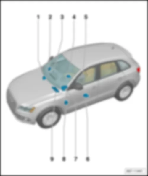
1 -  Fuse holder A -SA-
q   Fitting location: → chapter
1 -  Battery isolation relay fuse
q   Fitting location next to second battery
q   Battery isolation relay fuse -S171- , Special vehicle fuse 15 -S305- , 125A
q   Second battery fuse -S65-
q   Fuse 4 (30) -S207- , 110A
q   Fuse 5 (30) -S208- , 110A
q   Fuse 6 (30) -S209- , 200A
2 -  Fuse holder C -SC-
q   Fitting location for models with left-hand drive, up to and including model year 2009: → chapter
q   Fitting location for models with right-hand drive, up to and including model year 2009: → Anchor
q   Fitting location for models with left-hand drive, from model year 2010: → chapter
q   Fitting location for models with right-hand drive, from model year 2010: → Anchor
q   Fitting location for models with left-hand drive, from model year 2013: → chapter
q   Fitting location for models with right-hand drive, from model year 2013: → Anchor
3 -  Relay/fuse holder with onboard supply control unit -J519-
q   Fitting location for models with left-hand drive: → chapter
q   Fitting location for models with right-hand drive: → Anchor
4 -  6-pin coupling station of A-pillar driver side
q   Fitting location for models with left-hand drive: → chapter
q   Fitting location for models with right-hand drive: → Anchor
5 -  3-pin relay/fuse holder
q   Fitting location for models with left-hand drive: → chapter
q   Fitting location for models with right-hand drive: → Anchor
6 -  Relay/fuse holder B -SB-
q   Fitting location for models with left-hand drive, up to and including model year 2012: → chapter
q   Fitting location for models with right-hand drive, up to and including model year 2012: → Anchor
q   Fitting location for models with high-voltage system (hybrid), up to and including model year 2012: → chapter
q   Fitting location for models with left-hand drive, from model year 2013: → Anchor
q   Fitting location for models with right-hand drive, from model year 2013: → Anchor
7 -  Terminal 30 wiring junction 2 -TV22- with jump start socket -U6-
q   Fitting location for models with high-voltage system, up to May 2012: → chapter
q   Fitting location for models with high-voltage system, from June 2012: → chapter
q   Fitting location for models with high-voltage system (hybrid) from June 2011: → chapter
8 -  6-pin coupling station of A-pillar passenger side
q   Fitting location for models with left-hand drive: → chapter
q   Fitting location for models with right-hand drive: → Anchor
9 -  Fuse holder D -SD-
q   Fitting location for models with left-hand drive: → chapter
q   Fitting location for models with right-hand drive: → Anchor
10 -  Relay/fuse holder F -SF-
q   Fitting location, up to and including model year 2009: → chapter
q   Fitting location from model year 2010: → chapter
q   Fitting location, from model year 2013: → chapter


AUDI Q5 2009 Fuse holder A SA

Fuse holder A -SA-
1)  not for models with high-voltage system (hybrid)
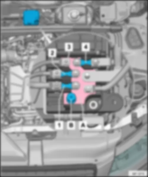
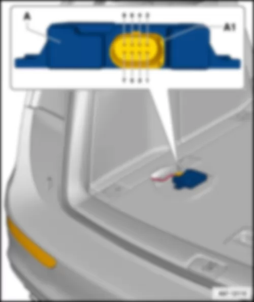
Fitting location:
On battery positive pole, in luggage compartment.
   
AUDI Q5 2009 Fuse holder A SA https://portal-diagnostov.com/license.html
https://portal-diagnostov.com/license.html Automotive Electricians Portal FZCO Automotive Electricians Portal FZCO
Получить доступ ко всем электросхемам автомобиляDownload PDF file
A -  Battery isolation igniter -N253-
1 -  Fuse 1 on fuse holder A -SA1- → Note , → chapter
2 -  Fuse 2 on fuse holder A -SA2- → Note , → chapter
3 -  Fuse 3 on fuse holder A -SA3- → Note , → chapter

Fuses on fuse holder A -SA-
2)  for models with left-hand drive only
3)  for models with right-hand drive only
4)  not for models with high-voltage system (hybrid)
5)  for models with taxi equipment only
6)  for models with 7-speed dual clutch gearbox only
7)  for models with no special criminal investigation department / doctor equipment only
   
No.   Current flow diagram designation Nominal value   Function/component Terminal
1 - Fuse 1 on fuse holder A -SA1- → Note 110 A - Onboard supply
Engine component supply
Reducing agent metering system relay -J963-
30
2 - Fuse 2 on fuse holder A -SA2- → Note 110 A - Onboard supply
Engine component supply
ABS control unit fuse 1 -S123- → Note
30
3 - Fuse 3 on fuse holder A -SA3- → Note 40 A
50 A → Note → Note
110 A → Note
80 A → Note
- Option for driving school
Option for hire car
Option for authorities
Mechatronic unit for dual clutch gearbox -J743- → Note
ABS control unit fuse 1 -S123- → Note
ABS control unit fuse 2 -S124- → Note
ABS control unit fuse 3 -S137- → Note
30


AUDI Q5 2009

Relay/fuse holder B -SB- , up to and including model year 2012
Fitting location, relay/fuse holder B -SB- for models with left-hand drive, up to model year 2012:
In electronics box in plenum chamber, driver side.
8)  for models with 4-cylinder diesel engine only
9)  for models with 6-cylinder diesel engine only
10)  for models with 4-cylinder petrol engine with high-voltage system (hybrid) only
11)  for models with 6-cylinder petrol engine only
  Note:
t  Figure shows left-hand drive model.
t  Fitting location for models with right-hand drive: → Anchor
   
AUDI Q5 2009 https://portal-diagnostov.com/license.html
https://portal-diagnostov.com/license.html Automotive Electricians Portal FZCO Automotive Electricians Portal FZCO
Получить доступ ко всем электросхемам автомобиляDownload PDF file
K -  Engine glow plug strip fuse -S39- → Note , 60 A
K -  Engine glow plug strip fuse -S39- → Note , 80 A
K -  Secondary air pump fuse -S130- → Note → Note , 50 A
L -  Fuse 1 -S131- → Note , 50 A
L -  NOx sender fuse -S360- → Note , 5 A
ST1 -  Fuse carrier 1
t  Fuse assignment → chapter

Fitting location, relay/fuse holder B -SB- for models with right-hand drive, up to model year 2012:
In electronics box in plenum chamber, driver side.
12)  for models with 4-cylinder diesel engine only
13)  for models with 6-cylinder diesel engine only
14)  for models with 4-cylinder petrol engine with high-voltage system (hybrid) only
15)  for models with 6-cylinder petrol engine only
  Note:
t  Figure​shows​right-hand drive​model.
t  Figure for models with left-hand drive → Anchor
   
AUDI Q5 2009 https://portal-diagnostov.com/license.html
https://portal-diagnostov.com/license.html Automotive Electricians Portal FZCO Automotive Electricians Portal FZCO
Получить доступ ко всем электросхемам автомобиляDownload PDF file
K -  Engine glow plug strip fuse -S39- → Note , 60 A
K -  Engine glow plug strip fuse -S39- → Note , 80 A
K -  Secondary air pump fuse -S130- → Note → Note , 50 A
L -  Fuse 1 -S131- → Note , 50 A
L -  NOx sender fuse -S360- → Note , 5 A
ST1 -  Fuse carrier 1
t  Fuse assignment → chapter

Fuses in fuse carrier ST1 on fuse holder B -SB- (black) for models without high-voltage system (hybrid), up to and including model year 2012
Fuse colours
35 A -  green/blue
30 A -  green
25 A -  white
20 A -  yellow
15 A -  blue
10 A -  red
7,5 A -  brown
5 A -  beige
16)  for models with 4-cylinder petrol engine (1.8 l TFSI) only
17)  for models with 4-cylinder petrol engine (2.0 l TFSI) only
18)  for models with 6-cylinder petrol engine (3.2 l FSI) only
19)  for models with 6-cylinder petrol engine (3.0 l TFSI) only
20)  for models with 4-cylinder diesel engine (2.0 l TDI) only
21)  for models with 4-cylinder diesel engine (2.0 l TDI - EU3) only
22)  for models with 4-cylinder diesel engine (2.0 l TDI - gen. 2) only
23)  for models with 6-cylinder diesel engine only
   
No.   Current flow diagram designation Nominal value   Function/component Terminal
1 - Fuse 1 on fuse holder B -SB1- 15 A - Automatic gearbox control unit -J217-
Mechatronic unit for dual clutch gearbox -J743-
30
2 - Fuse 2 on fuse holder B -SB2- 5 A - Oil level and oil temperature sender -G266- 87
3 - Fuse 3 on fuse holder B -SB3- 5 A - Air mass meter -G70-
,Engine control unit -J623-
15
4   Fuse 4 on fuse holder B -SB4- 5 A - Engine control unit -J623- 30
5   Fuse 5 on fuse holder B -SB5- 10 A → Note
15 A → Note
15 A → Note
15 A → Note
15 A → Note
15 A → Note
15 A → Note
20 A → Note
- Automatic glow period control unit -J179-
Secondary air pump relay -J299-
Throttle valve module -J338-
Low heat output relay -J359-
High heat output relay -J360-
Charge pressure control solenoid valve -N75-
Heater element for crankcase breather -N79-
Activated charcoal filter solenoid valve 1 -N80-
Secondary air inlet valve -N112-
Left electrohydraulic engine mounting solenoid valve -N144-
Right electrohydraulic engine mounting solenoid valve -N145-
Variable intake manifold changeover valve -N156-
Air filter bypass flap valve -N275-
Fuel pressure regulating valve -N276-
Fuel metering valve -N290-
Injector, cylinder 9 -N299-
Intake manifold flap valve -N316-
Secondary air inlet valve 2 -N320-
Exhaust gas recirculation cooler changeover valve -N345-
Exhaust gas recirculation cooler changeover valve -N428-
Fuel system diagnostic pump -V144-
87
6   Fuse 6 on fuse holder B -SB6- 15 A - Engine control unit -J623- 87
7   Fuse 7 on fuse holder B -SB7- 10 A → Note
10 A → Note
10 A → Note
10 A → Note
10 A → Note
10 A → Note
15 A → Note
15 A → Note
- Actuator 1 for camshaft adjustment -F366-
to
actuator 8 for camshaft adjustment -F373-
Actuator 9 for camshaft adjustment -F374-
to
actuator 12 for camshaft adjustment -F377-
Continued coolant circulation relay -J151-
Additional coolant pump relay -J496-
Charge pressure control solenoid valve -N75-
Activated charcoal filter solenoid valve 1 -N80-
Left electrohydraulic engine mounting solenoid valve -N144-
Right electrohydraulic engine mounting solenoid valve -N145-
Camshaft control valve 1 -N205-
Camshaft control valve 2 -N208-
Turbocharger air recirculation valve -N249-
Fuel pressure regulating valve -N276-
Fuel metering valve -N290-
Intake manifold flap valve -N316-
Exhaust camshaft control valve 1 -N318-
Exhaust camshaft control valve 2 -N319-
Climatronic coolant shut-off valve -N422-
Valve for oil pressure control -N428-
Fuel system diagnostic pump -V144-
Charge air cooling pump -V188-
87
8   Fuse 8 on fuse holder B -SB8- 5 A → Note
10 A → Note
10 A → Note
10 A → Note
20 A → Note
20 A → Note
20 A → Note
20 A → Note
- Pump for exhaust gas recirculation cooler -V400-
Ignition coil 1 with output stage -N70-
Ignition coil 2 with output stage -N127-
Ignition coil 3 with output stage -N291-
Ignition coil 4 with output stage -N292-
Ignition coil 5 with output stage -N323-
Ignition coil 6 with output stage -N324-
87
9   Fuse 9 on fuse holder B -SB9- 5 A → Note
15 A → Note
15 A → Note
20 A → Note
20 A → Note
20 A → Note
- Relay for supplementary fuel pump -J832-
Lambda probe 1 heater after catalytic converter -Z29-
Lambda probe 2 heater after catalytic converter -Z30-
87
10   Fuse 10 on fuse holder B -SB10- 10 A → Note
15 A → Note
15 A → Note
15 A → Note
15 A → Note
15 A → Note
15 A → Note
- Lambda probe heater -Z19-
Lambda probe heater 2 -Z28-
Lambda probe 1 heater after catalytic converter -Z29-
87
11   Fuse 11 on fuse holder B -SB11- 5 A - Radiator fan control unit -J293-
Radiator fan control unit 2 -J671-
87
12 - Fuse 12 on fuse holder B -SB12- 5 A - Air mass meter -G70-
Automatic gearbox control unit -J217-
Mechatronic unit for dual clutch gearbox -J743-
15

   
Fuses in fuse carrier ST1 on fuse holder B -SB- (black) with high-voltage system (hybrid), up to and including model year 2012
AUDI Q5 2009 https://portal-diagnostov.com/license.html
https://portal-diagnostov.com/license.html Automotive Electricians Portal FZCO Automotive Electricians Portal FZCO
Получить доступ ко всем электросхемам автомобиляDownload PDF file
K -  Secondary air pump fuse -S130- , 50 A
L -  Gearbox hydraulic pump relay -J510- , 50 A
ST1 -  Fuse carrier 1, fuses

Fuse colours
35 A -  green/blue
30 A -  green
25 A -  white
20 A -  yellow
15 A -  blue
10 A -  red
7,5 A -  brown
5 A -  beige
   
No.   Current flow diagram designation Nominal value   Function/component Terminal
1 - Fuse 1 on fuse holder B -SB1- 15 A - Automatic gearbox control unit -J217-
Mechatronic unit for dual clutch gearbox -J743-
30
2 - Fuse 2 on fuse holder B -SB2- 5 A - Oil level and oil temperature sender -G266- 87
3 - Fuse 3 on fuse holder B -SB3- 5 A - Air mass meter -G70-
Engine control unit -J623-
Power and control electronics for electric drive -JX1-
87
4   Fuse 4 on fuse holder B -SB4- 5 A - Engine control unit -J623- 30
5   Fuse 5 on fuse holder B -SB5- 10 A - Coolant shut-off valve -N82-
Fuel pressure regulating valve -N276-
87
6   Fuse 6 on fuse holder B -SB6- 15 A - Engine control unit -J623- 87
7   Fuse 7 on fuse holder B -SB7- 15 A - Actuator 1 for camshaft adjustment -F366-
to
actuator 8 for camshaft adjustment -F373-
Secondary air pump relay -J299-
Charge pressure control solenoid valve -N75-
Activated charcoal filter solenoid valve 1 -N80-
Secondary air inlet valve -N112-
Left electrohydraulic engine mounting solenoid -N144-
Right electrohydraulic engine mounting solenoid -N145-
Camshaft control valve 1 -N205-
Turbocharger air recirculation valve -N249-
Intake manifold flap valve -N316-
Exhaust flap 1 valve -N321-
Climatronic coolant shut-off valve -N422-
Valve for oil pressure control -N428-
Continued coolant circulation pump -V51-
Coolant pump for high-temperature circuit -V467-
87
8   Fuse 8 on fuse holder B -SB8- 5 A - Power and control electronics for electric drive -JX1- 30
9   Fuse 9 on fuse holder B -SB9- 5 A - Power steering control unit -J500- 87
10   Fuse 10 on fuse holder B -SB10- 15 A - Lambda probe heater -Z19-
Lambda probe 1 heater after catalytic converter -Z29-
87
11   Fuse 11 on fuse holder B -SB11- 5 A - Radiator fan control unit -J293-
Radiator fan -V7-
Radiator fan 2 -V177-
87
12   Fuse 12 on fuse holder B -SB12- 5 A - Automatic gearbox control unit -J217-
Mechatronic unit for dual clutch gearbox -J743-
87
13   Fuse 13 on fuse holder B -SB13- 5 A - Control unit for air conditioning compressor -J842-
Electrical air conditioner compressor -V470-
87
14   Fuse 14 on fuse holder B -SB14- 20 A - Ignition coil 1 with output stage -N70-
Ignition coil 2 with output stage -N127-
Ignition coil 3 with output stage -N291-
Ignition coil 4 with output stage -N292-
87
15   Fuse 15 on fuse holder B -SB15-   - not assigned  
16   Fuse 16 on fuse holder B -SB16- 5 A - Low-temperature circuit coolant pump -V468- 87
17 - Fuse 17 on fuse holder B -SB17- 5 A - Engine control unit -J623- 50


AUDI Q5 2009

Relay/fuse holder B -SB- , from model year 2013
Fitting location, relay/fuse holder B -SB- for models with left-hand drive, from model year 2013:
In electronics box in plenum chamber, driver side.
24)  for models with 4-cylinder diesel engine only
25)  for models with 6-cylinder diesel engine only
26)  for models with 4-cylinder petrol engine with high-voltage system (hybrid) only
27)  for models with 6-cylinder petrol engine only
  Note:
t  Figure shows left-hand drive model.
t  Fitting location for models with right-hand drive: → Anchor
   
AUDI Q5 2009 https://portal-diagnostov.com/license.html
https://portal-diagnostov.com/license.html Automotive Electricians Portal FZCO Automotive Electricians Portal FZCO
Получить доступ ко всем электросхемам автомобиляDownload PDF file
K -  Engine glow plug strip fuse -S39- , 60 A → Note
K -  Engine glow plug strip fuse -S39- , 80 A → Note
K -  Secondary air pump fuse -S130- , 50 A → Note
L -  Gearbox hydraulic pump relay -J510- , 50 A → Note
ST1 -  Fuse carrier 1, fuses

Fitting location, relay/fuse holder B -SB- for models with right-hand drive, from model year 2013:
In electronics box in plenum chamber, driver side.
28)  for models with 4-cylinder diesel engine only
29)  for models with 6-cylinder diesel engine only
30)  for models with 4-cylinder petrol engine with high-voltage system (hybrid) only
31)  for models with 6-cylinder petrol engine only
  Note:
t  Figure​shows​right-hand drive​model.
t  Figure for models with left-hand drive → Anchor
   
AUDI Q5 2009 https://portal-diagnostov.com/license.html
https://portal-diagnostov.com/license.html Automotive Electricians Portal FZCO Automotive Electricians Portal FZCO
Получить доступ ко всем электросхемам автомобиляDownload PDF file
K -  Engine glow plug strip fuse -S39- , 60 A → Note
K -  Engine glow plug strip fuse -S39- , 80 A → Note
K -  Secondary air pump fuse -S130- , 50 A → Note
L -  Gearbox hydraulic pump relay -J510- , 50 A → Note
ST1 -  Fuse carrier 1, fuses

Fuses in fuse carrier ST1 on fuse holder B -SB- (black), from model year 2013
Fuse colours
35 A -  green/blue
30 A -  green
25 A -  white
20 A -  yellow
15 A -  blue
10 A -  red
7,5 A -  brown
5 A -  beige
32)  for models with 4-cylinder petrol engine (2.0 l TFSI - gen. only 3) only
33)  for models with 4-cylinder petrol engine with high-voltage system (hybrid) only
34)  for models with 6-cylinder petrol engine (3.0 l TFSI) only
35)  for models with 4-cylinder diesel engine (2.0 l TDI) only
36)  for models with 6-cylinder diesel engine (3.0 l TDI) only
37)  for models with 6-cylinder diesel engine (3.0 l TDI - BIN 5) only
   
No.   Current flow diagram designation Nominal value   Function/component Terminal
1 - Fuse 1 on fuse holder B -SB1- 15 A - Automatic gearbox control unit -J217-
Mechatronic unit for dual clutch gearbox -J743-
30
2 - Fuse 2 on fuse holder B -SB2- 5 A - Oil level and oil temperature sender -G266- 87
3 - Fuse 3 on fuse holder B -SB3- 5 A - Engine control unit -J623-
Power and control electronics for electric drive -JX1-
87
4   Fuse 4 on fuse holder B -SB4- 5 A - Engine control unit -J623- 30
5   Fuse 5 on fuse holder B -SB5- 5 A → Note → Note
10 A → Note
→ Note
→ Note
- Coolant shut-off valve -N82-
Fuel pressure regulating valve -N276-
Air mass meter -G70-
87
6   Fuse 6 on fuse holder B -SB6- 15 A - Engine control unit -J623- 87
7   Fuse 7 on fuse holder B -SB7- 10 A → Note
→ Note
→ Note
15 A → Note
→ Note
- Actuator 1 for camshaft adjustment -F366-
to
actuator 8 for camshaft adjustment -F373-
Secondary air pump relay -J299-
Charge pressure control solenoid valve -N75-
Activated charcoal filter solenoid valve 1 -N80-
Secondary air inlet valve -N112-
Left electrohydraulic engine mounting solenoid -N144-
Right electrohydraulic engine mounting solenoid -N145-
Camshaft control valve 1 -N205-
Turbocharger air recirculation valve -N249-
Intake manifold flap valve -N316-
Exhaust flap 1 valve -N321-
Climatronic coolant shut-off valve -N422-
Valve for oil pressure control -N428-
Continued coolant circulation pump -V51-
Coolant pump for high-temperature circuit -V467-
87
8   Fuse 8 on fuse holder B -SB8- 5 A → Note → Note
10 A → Note
15 A → Note
- Power and control electronics for electric drive -JX1-
NOx sender -G295-
NOx sender 2 -G687-
Control unit for NOx sender -J583-
Control unit for NOx sender 2 -J881-
Brake servo relay -J569-
30
9   Fuse 9 on fuse holder B -SB9- 5 A - Engine control unit -J623- 87
10   Fuse 10 on fuse holder B -SB10- 10 A → Note → Note
15 A → Note → Note
→ Note
- Lambda probe heater -Z19-
Lambda probe 1 heater after catalytic converter -Z29-
Power steering control unit -J500-
87
11   Fuse 11 on fuse holder B -SB11- 5 A - Radiator fan control unit -J293-
Radiator fan -V7-
Radiator fan 2 -V177-
87
12   Fuse 12 on fuse holder B -SB12- 5 A - Automatic gearbox control unit -J217-
Mechatronic unit for dual clutch gearbox -J743-
87
13   Fuse 13 on fuse holder B -SB13- 5 A → Note - Control unit for air conditioning compressor -J842-
Electrical air conditioner compressor -V470-
87
14   Fuse 14 on fuse holder B -SB14- 5 A → Note
20 A → Note
→ Note
→ Note
- Engine component current supply relay 2 -J976-
Ignition coil 1 with output stage -N70-
Ignition coil 2 with output stage -N127-
Ignition coil 3 with output stage -N291-
Ignition coil 4 with output stage -N292-
Ignition coil 5 with output stage -N323-
Ignition coil 6 with output stage -N324-
Climatronic coolant shut-off valve -N422-
Pump for exhaust gas recirculation cooler -V400-
87
15   Fuse 15 on fuse holder B -SB15- 5 A - Power steering control unit -J500-
Lambda probe heater -Z19-
Lambda probe 1 heater after catalytic converter -Z29-
87
16   Fuse 16 on fuse holder B -SB16- 15 A - Map-controlled engine cooling system thermostat -F265-
Automatic glow period control unit -J179-
Secondary air pump relay -J299-
Low heat output relay -J359-
High heat output relay -J360-
Additional coolant pump relay -J496-
Gearbox cooling circuit relay -J696-
Charge pressure control solenoid valve -N75-
Heater element for crankcase breather -N79-
Activated charcoal filter solenoid valve 1 -N80-
Secondary air inlet valve -N112-
Left electrohydraulic engine mounting solenoid valve -N144-
Right electrohydraulic engine mounting solenoid valve -N145-
Air filter bypass flap valve -N275-
Secondary air inlet valve 2 -N320-
Exhaust gas recirculation cooler changeover valve -N345-
Valve for oil pressure control -N428-
Coolant valve for gearbox -N488-
Coolant valve for cylinder head -N489-
Actuator for engine temperature regulation -N493-
Charge air cooling pump -V188-
Crankcase breather valve -V546-
87
17 - Fuse 17 on fuse holder B -SB17- 10 A → Note
15A → Note
- Coolant pump for low-temperature circuit -V468-
Lambda probe heater -Z19-
Lambda probe 1 heater after catalytic converter -Z29-
50

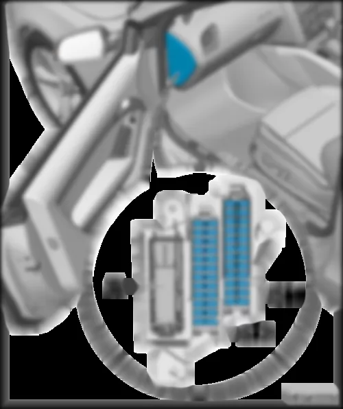
Fuse holder C -SC- , up to model year 2009
Fitting location, fuse holder C -SC- for models with left-hand drive, up to model year 2009:
Below the dash panel cover, driver side.
  Note:
t  Figure shows left-hand drive model.
t  Figure for models with right-hand drive → Anchor
   
AUDI Q5 2009 https://portal-diagnostov.com/license.html
https://portal-diagnostov.com/license.html Automotive Electricians Portal FZCO Automotive Electricians Portal FZCO
Получить доступ ко всем электросхемам автомобиляDownload PDF file
ST1 -  Fuse carrier 1, fuses → chapter
ST2 -  Fuse carrier 2, fuses → chapter
ST3 -  Fuse carrier 3, fuses → chapter

Fitting location, fuse holder C -SC- for models with right-hand drive, up to model year 2009:
Below the dash panel cover, driver side.
  Note:
t  Figure​shows​right-hand drive​model.
t  Figure for models with left-hand drive → Anchor
   
AUDI Q5 2009 https://portal-diagnostov.com/license.html
https://portal-diagnostov.com/license.html Automotive Electricians Portal FZCO Automotive Electricians Portal FZCO
Получить доступ ко всем электросхемам автомобиляDownload PDF file
ST1 -  Fuse carrier 1, fuses → chapter
ST2 -  Fuse carrier 2, fuses → chapter
ST3 -  Fuse carrier 3, fuses → chapter

Fuses in fuse carrier ST1 on fuse holder C -SC- (black)
Fuse colours
35 A -  green/blue
30 A -  green
25 A -  white
20 A -  yellow
15 A -  blue
10 A -  red
7,5 A -  brown
5 A -  beige
   
No.   Current flow diagram designation Nominal value   Function/component Terminal
1 - Fuse 1 on fuse holder C -SC1- 5 A - Active steering control unit -J792- 15
2 - Fuse 2 on fuse holder C -SC2- 5 A - Clutch pedal switch -F36-
Clutch pedal switch for engine start -F194-
Clutch position sender -G476-
15
3 - Fuse 3 on fuse holder C -SC3- 5 A - Garage door operating unit -E284-
Garage door operation control unit -J530-
15
4 - Fuse 4 on fuse holder C -SC4- 10 A - Lane departure warning control unit -J759- 15
5 - Fuse 5 on fuse holder C -SC5- 5 A - Air quality sensor -G238- 15
6 - Fuse 6 on fuse holder C -SC6- 5 A - Headlight range control regulator -E102-
Headlight range control unit -J431-
Output module for right headlight -J668-
Control unit for cornering light and headlight range control -J745-
Left headlight range control motor -V48-
Right headlight range control motor -V49-
15
7 - Fuse 7 on fuse holder C -SC7- 5 A - Output module for left headlight -J667- 15
8 - Fuse 8 on fuse holder C -SC8- 5 A - Onboard supply control unit -J519- 15
9 - Fuse 9 on fuse holder C -SC9- 5 A - Automatic anti-dazzle interior mirror -Y7- 15
10 - Fuse 10 on fuse holder C -SC10- 5 A - Selector lever sensors control unit -J587-
Selector lever lock solenoid -N110-
15
11 - Fuse 11 on fuse holder C -SC11- 5 A - Left washer jet heater element -Z20-
Right washer jet heater element -Z21-
15
12 - Fuse 12 on fuse holder C -SC12- 5 A - Refrigerant pressure and temperature sender -G395- 15

Fuses in fuse carrier ST2 on fuse holder C -SC- (brown)
38)  for models with petrol engine only
39)  for models with diesel engine only
   
No.   Current flow diagram designation Nominal value   Function/component Terminal
1 - Fuse 1 on fuse holder C -SC1- 5 A - Circulation pump relay -J160- 87
2 - Fuse 2 on fuse holder C -SC2- 5 A - Clutch pedal switch -F36-
Clutch pedal switch for engine start -F194-
Clutch position sender -G476-
87
3 - Fuse 3 on fuse holder C -SC3- 20 A → Note
25 A → Note
- Fuel system pressurisation pump -G6-
Fuel pump control unit -J538-
87
4 - Fuse 4 on fuse holder C -SC4- 5 A - Circulation pump relay -J160- 15
5 - Fuse 5 on fuse holder C -SC5- 30 A - Onboard supply control unit -J519- 30
6 - Fuse 6 on fuse holder C -SC6- 10 A - ABS control unit -J104- 30
7 - Fuse 7 on fuse holder C -SC7- 25 A - Horn relay -J413- 30
8 - Fuse 8 on fuse holder C -SC8- 30 A - Driver door control unit -J386-
Rear left door control unit -J388-
30
9 - Fuse 9 on fuse holder C -SC9- 30 A - Wiper motor control unit -J400- 30
10 - Fuse 10 on fuse holder C -SC10- 25 A - ABS control unit -J104- 30
11 - Fuse 11 on fuse holder C -SC11- 15 A - Driver door control unit -J386-
Rear left door control unit -J388-
30
12 - Fuse 12 on fuse holder C -SC12- 5 A - Rain and light sensor -G397- 30

   
Fuses in fuse carrier ST3 on fuse holder C -SC- (red)
No.   Current flow diagram designation Nominal value   Function/component Terminal
1 - Fuse 1 on fuse holder C -SC1-   - not assigned
2 - Fuse 2 on fuse holder C -SC2-   - not assigned
3 - Fuse 3 on fuse holder C -SC3- 10 A - Driver seat lumbar support adjustment switch -E176-
Front passenger seat lumbar support adjustment switch -E177-
30
4 - Fuse 4 on fuse holder C -SC4- 35 A - Active steering control unit -J792- 30
5 - Fuse 5 on fuse holder C -SC5- 10 A - Heated cup holder -Z105- 30
6 - Fuse 6 on fuse holder C -SC6- 35 A - Onboard supply control unit -J519- 30
7 - Fuse 7 on fuse holder C -SC7- 20 A - Onboard supply control unit -J519- 30
8 - Fuse 8 on fuse holder C -SC8- 30 A - Onboard supply control unit -J519- 30
9 - Fuse 9 on fuse holder C -SC9- 20 A - Sliding sunroof adjustment control unit -J245- 30
10 - Fuse 10 on fuse holder C -SC10- 30 A - Onboard supply control unit -J519- 30
11 - Fuse 11 on fuse holder C -SC11- 20 A - Sunroof roller blind control unit -J394- 30
12 - Fuse 12 on fuse holder C -SC12- 5 A - Alarm horn -H12-
Anti-theft alarm sensor -G578-
30


AUDI Q5 2009

Fuse holder C -SC- , from model year 2010
Fitting location, fuse holder C -SC- for models with left-hand drive, from model year 2010:
Below the dash panel cover, driver side.
  Note:
t  Figure shows left-hand drive model.
t  Figure for models with right-hand drive → Anchor
   
AUDI Q5 2009 https://portal-diagnostov.com/license.html
https://portal-diagnostov.com/license.html Automotive Electricians Portal FZCO Automotive Electricians Portal FZCO
Получить доступ ко всем электросхемам автомобиляDownload PDF file
ST1 -  Fuse carrier 1, fuses → chapter
ST2 -  Fuse carrier 2, fuses → chapter
ST3 -  Fuse carrier 3, fuses → chapter

Fitting location, fuse holder C -SC- for models with right-hand drive, from model year 2010:
Below the dash panel cover, driver side.
  Note:
t  Figure​shows​right-hand drive​model.
t  Figure for models with left-hand drive → Anchor
   
AUDI Q5 2009 https://portal-diagnostov.com/license.html
https://portal-diagnostov.com/license.html Automotive Electricians Portal FZCO Automotive Electricians Portal FZCO
Получить доступ ко всем электросхемам автомобиляDownload PDF file
ST1 -  Fuse carrier 1, fuses → chapter
ST2 -  Fuse carrier 2, fuses → chapter
ST3 -  Fuse carrier 3, fuses → chapter

Fuses in fuse carrier ST1 on fuse holder C -SC- (black)
Fuse colours
35 A -  green/blue
30 A -  green
25 A -  white
20 A -  yellow
15 A -  blue
10 A -  red
7,5 A -  brown
5 A -  beige
   
No.   Current flow diagram designation Nominal value   Function/component Terminal
1 - Fuse 1 on fuse holder C -SC1- 5 A - Active steering control unit -J792- 15
2 - Fuse 2 on fuse holder C -SC2-   - not assigned
3 - Fuse 3 on fuse holder C -SC3- 5 A - Garage door operating unit -E284-
Garage door operation control unit -J530-
15
4 - Fuse 4 on fuse holder C -SC4- 10 A - Lane departure warning control unit -J759- 15
5 - Fuse 5 on fuse holder C -SC5- 5 A - Air quality sensor -G238- 15
6 - Fuse 6 on fuse holder C -SC6- 5 A - Headlight range control regulator -E102-
Headlight range control unit -J431-
Output module for right headlight -J668-
Control unit for cornering light and headlight range control -J745-
Front left headlight -MX1-
Right front headlight -MX2-
15
7 - Fuse 7 on fuse holder C -SC7- 5 A - Output module for left headlight -J667- 15
8 - Fuse 8 on fuse holder C -SC8- 5 A - Onboard supply control unit -J519- 15
9 - Fuse 9 on fuse holder C -SC9- 5 A - Adaptive cruise control unit -J428- 15
10 - Fuse 10 on fuse holder C -SC10- 5 A - Clutch position sender -G476-
Selector lever sensors control unit -J587-
Selector lever lock solenoid -N110-
15
11 - Fuse 11 on fuse holder C -SC11- 5 A - Left washer jet heater element -Z20-
Right washer jet heater element -Z21-
15
12 - Fuse 12 on fuse holder C -SC12- 5 A - Refrigerant pressure and temperature sender -G395- 15
13   Fuse 13 on fuse holder C -SC13- 5 A - 18-pin connector -T18a- 15
14   Fuse 14 on fuse holder C -SC14- 5 A - Hazard warning lights button -E229-
Airbag control unit -J234-
Seat occupied recognition control unit -J706-
Indicator lamp for hazard warning light -K6-
15
15   Fuse 15 on fuse holder C -SC15- 25 A - ABS control unit -J104-
Fuse carrier 2 -ST2- on fuse holder C -SC-
Fuse carrier 1 -ST1- on fuse holder D -SD-
Fuse carrier 4 -ST4- on fuse holder F -SF-
15
16 - Fuse 16 on fuse holder C -SC16- 40 A - Starter motor relay -J53-
Starter motor relay 2 -J695-
Fuse carrier 1 -ST1- with fuse 3 on fuse holder B -SB3-
Fuse carrier 1 -ST1- with fuse 12 on fuse holder B -SB12-
15

Fuses in fuse carrier ST2 on fuse holder C -SC- (brown)
40)  for models with petrol engine only
41)  for models with 4-cylinder petrol engine with high-voltage system (hybrid) only
42)  for models with diesel engine (without J538) only
43)  for models with diesel engine (with J538) only
44)  for models with left-hand drive only
45)  for models without seat ventilation only
46)  for models with seat ventilation only
   
No.   Current flow diagram designation Nominal value   Function/component Terminal
1 - Fuse 1 on fuse holder C -SC1- 5 A - Automatic anti-dazzle interior mirror -Y7- 15
2 - Fuse 2 on fuse holder C -SC2- 5 A - Brake light switch -F-
Brake pedal position sender -G100-
Clutch position sender -G476-
87
3 - Fuse 3 on fuse holder C -SC3- 20 A → Note
25 A → Note
25 A → Note
25 A → Note
- Fuel system pressurisation pump -G6-
Fuel pump control unit -J538-
87
4 - Fuse 4 on fuse holder C -SC4- 10 A
25 A → Note
- Vacuum pump relay -J318-
Circulation pump relay -J160-
Pump for reducing agent -V437-
15
30 → Note
5 - Fuse 5 on fuse holder C -SC5- 15 A → Note
30 A → Note
- Onboard supply control unit -J519- 30
6 - Fuse 6 on fuse holder C -SC6- 5 A → Note
10 A
- ABS control unit -J104- → Note 30
7 - Fuse 7 on fuse holder C -SC7- 25 A - Horn relay -J413- 30
8 - Fuse 8 on fuse holder C -SC8- 30 A - Left doors 30
9 - Fuse 9 on fuse holder C -SC9- 30 A - Wiper motor control unit -J400- 30
10 - Fuse 10 on fuse holder C -SC10- 25 A - ABS control unit -J104- → Note 30
11 - Fuse 11 on fuse holder C -SC11- 15 A - Left doors 30
12 - Fuse 12 on fuse holder C -SC12- 5 A - Rain and light sensor -G397- 30

   
Fuses in fuse carrier ST3 on fuse holder C -SC- (red)
No.   Current flow diagram designation Nominal value   Function/component Terminal
1 - Fuse 1 on fuse holder C -SC1-   - not assigned
2 - Fuse 2 on fuse holder C -SC2-   - not assigned
3 - Fuse 3 on fuse holder C -SC3- 10 A - Driver seat lumbar support adjustment switch -E176-
Front passenger seat lumbar support adjustment switch -E177-
30
4 - Fuse 4 on fuse holder C -SC4- 35 A - Active steering control unit -J792- 30
5 - Fuse 5 on fuse holder C -SC5- 10 A - Cup holder with heater and cooling element -Z105- 30
6 - Fuse 6 on fuse holder C -SC6- 35 A - Onboard supply control unit -J519- 30
7 - Fuse 7 on fuse holder C -SC7- 20 A - Onboard supply control unit -J519- 30
8 - Fuse 8 on fuse holder C -SC8- 30 A - Onboard supply control unit -J519- 30
9 - Fuse 9 on fuse holder C -SC9- 20 A - Sliding sunroof adjustment control unit -J245- 30
10 - Fuse 10 on fuse holder C -SC10- 30 A - Onboard supply control unit -J519- 30
11 - Fuse 11 on fuse holder C -SC11- 20 A - Sunroof roller blind control unit -J394- 30
12 - Fuse 12 on fuse holder C -SC12- 5 A - Alarm horn -H12-
Anti-theft alarm sensor -G578-
30


AUDI Q5 2009

Fuse holder C -SC- , from model year 2013
Fitting location, fuse holder C -SC- for models with left-hand drive, from model year 2013:
Below the dash panel cover, driver side.
  Note:
t  Figure shows left-hand drive model.
t  Figure for models with right-hand drive → Anchor
   
AUDI Q5 2009 https://portal-diagnostov.com/license.html
https://portal-diagnostov.com/license.html Automotive Electricians Portal FZCO Automotive Electricians Portal FZCO
Получить доступ ко всем электросхемам автомобиляDownload PDF file
ST1 -  Fuse carrier 1, fuses → chapter
ST2 -  Fuse carrier 2, fuses → chapter
ST3 -  Fuse carrier 3, fuses → chapter

Fitting location, fuse holder C -SC- for models with right-hand drive, from model year 2013:
Below the dash panel cover, driver side.
  Note:
t  Figure​shows​right-hand drive​model.
t  Figure for models with left-hand drive → Anchor
   
AUDI Q5 2009 https://portal-diagnostov.com/license.html
https://portal-diagnostov.com/license.html Automotive Electricians Portal FZCO Automotive Electricians Portal FZCO
Получить доступ ко всем электросхемам автомобиляDownload PDF file
ST1 -  Fuse carrier 1, fuses → chapter
ST2 -  Fuse carrier 2, fuses → chapter
ST3 -  Fuse carrier 3, fuses → chapter

Fuses in fuse carrier ST1 on fuse holder C -SC- (black)
Fuse colours
35 A -  green/blue
30 A -  green
25 A -  white
20 A -  yellow
15 A -  blue
10 A -  red
7,5 A -  brown
5 A -  beige
   
No.   Current flow diagram designation Nominal value   Function/component Terminal
1 - Fuse 1 on fuse holder C -SC1- 5 A - Active steering control unit -J792- 15
2 - Fuse 2 on fuse holder C -SC2- 5 A - ABS control unit -J104- 15
3 - Fuse 3 on fuse holder C -SC3- 5 A - TCS and ESP button -E256-
Parking aid button -E266-
Garage door operating unit -E284-
Electromechanical parking brake button -E538-
Auto-hold button -E540-
Air quality sensor -G238-
Refrigerant pressure and temperature sender -G395-
Garage door operation control unit -J530-
Seat heating control unit -J882-
Relay for automatic anti-dazzle interior mirror -J910-
Automatic anti-dazzle interior mirror -Y7-
15
4 - Fuse 4 on fuse holder C -SC4- 10 A - Lane departure warning control unit -J759- 15
5 - Fuse 5 on fuse holder C -SC5- 15 A - Control unit for structure-borne sound -J869-
Engine sound generator control unit -J943-
15
6 - Fuse 6 on fuse holder C -SC6- 5 A - Headlight range control regulator -E102-
Front left headlight -MX1-
Front right headlight -MX2-
Left headlight range control motor -V48-
Right headlight range control motor -V49-
15
7 - Fuse 7 on fuse holder C -SC7- 5 A - Front left headlight -MX1- 15
8 - Fuse 8 on fuse holder C -SC8- 5 A - Electronically controlled damping control unit -J250-
Trailer detector control unit -J345-
Convenience system central control unit -J393-
All-wheel drive control unit -J492-
Voltage stabilizer -J532-
Control unit for electromechanical parking brake -J540-
15
9 - Fuse 9 on fuse holder C -SC9- 5 A - Adaptive cruise control unit -J428- 15
10 - Fuse 10 on fuse holder C -SC10- 5 A - Clutch position sender -G476-
Selector lever lock solenoid -N110-
15
11 - Fuse 11 on fuse holder C -SC11- 5 A - Lane change assist control unit -J769-
Lane change assist control unit 2 -J770-
15
12 - Fuse 12 on fuse holder C -SC12- 5 A - Onboard supply control unit -J519- 15
13   Fuse 13 on fuse holder C -SC13- 5 A - Airbag control unit -J234-
Seat occupied recognition control unit -J706-
Front passenger side airbag deactivated warning lamp -K145-
15
14   Fuse 14 on fuse holder C -SC14- 15 A - Rear window wiper motor -V12- 15
15   Fuse 15 on fuse holder C -SC15- 10 A - Supply, fuse carrier 1 -ST1-Fuse holder D -SD- 15
16 - Fuse 16 on fuse holder C -SC16- 40 A - Starter motor relay -J53-
Starter motor relay 2 -J695-
Supply, fuse carrier 1 -ST1-Fuse 3 on fuse holder B -SB3-
Supply, fuse carrier 1 -ST1-Fuse 12 on fuse holder B -SB12-
Fuse carrier 1 -ST1-Fuse 15 on fuse holder B -SB15-
15

Fuses in fuse carrier ST2 on fuse holder C -SC- (brown)
47)  for models without seat ventilation only
48)  for models with seat ventilation only
   
No.   Current flow diagram designation Nominal value   Function/component Terminal
1 - Fuse 1 on fuse holder C -SC1- 5 A - Exhaust flap valve -N220- 87
2 - Fuse 2 on fuse holder C -SC2- 5 A - Brake light switch -F- 87
3 - Fuse 3 on fuse holder C -SC3- 25 A - Fuel pump control unit -J538- 87
4 - Fuse 4 on fuse holder C -SC4- 5 A


25 A
- Clutch position sender -G476-
Pressure sender for reducing agent metering system -G686-
Control unit for reducing agent metering system -J880-
Pump for reducing agent -V437-
Heater for reducing-agent pump -Z103-
Vacuum pump relay -J318-
87
5 - Fuse 5 on fuse holder C -SC5- 15 A → Note
30 A → Note
- Onboard supply control unit -J519-
Control unit for front left seat ventilation -J800-
30
6 - Fuse 6 on fuse holder C -SC6- 5 A - ABS control unit -J104- 30
7 - Fuse 7 on fuse holder C -SC7- 15 A - Treble horn -H2-
Bass horn -H7-
Horn relay -J413-
30
8 - Fuse 8 on fuse holder C -SC8- 30 A - Front left door 30
9 - Fuse 9 on fuse holder C -SC9- 30 A - Wiper motor control unit -J400- 30
10 - Fuse 10 on fuse holder C -SC10- 25 A - ABS control unit -J104- 30
11 - Fuse 11 on fuse holder C -SC11- 30 A - Rear left door 30
12 - Fuse 12 on fuse holder C -SC12- 5 A - Rain and light sensor -G397- 30

   
Fuses in fuse carrier ST3, fuse holder C -SC- (red)
No.   Current flow diagram designation Nominal value   Function/component Terminal
1 - Fuse 1 on fuse holder C -SC1- - not assigned
2 - Fuse 2 on fuse holder C -SC2- - not assigned
3 - Fuse 3 on fuse holder C -SC3- 10 A - Driver seat lumbar support adjustment switch -E176-
Front passenger seat lumbar support adjustment switch -E177-
30
4 - Fuse 4 on fuse holder C -SC4- 35 A - Active steering control unit -J792- 30
5 - Fuse 5 on fuse holder C -SC5- 10 A - Cup holder with heater and cooling element -Z105- 30A
6 - Fuse 6 on fuse holder C -SC6- 35 A - Onboard supply control unit -J519- 30
7 - Fuse 7 on fuse holder C -SC7- 20 A - Onboard supply control unit -J519- 30
8 - Fuse 8 on fuse holder C -SC8- 30 A - Onboard supply control unit -J519- 30
9 - Fuse 9 on fuse holder C -SC9- 20 A - Sliding sunroof adjustment control unit -J245- 30
10 - Fuse 10 on fuse holder C -SC10- 30 A - Onboard supply control unit -J519- 30
11 - Fuse 11 on fuse holder C -SC11- 20 A - Sunroof roller blind control unit -J394- 30
12 - Fuse 12 on fuse holder C -SC12- 5 A - Anti-theft alarm sensor -G578-
Alarm horn -H12-
30


AUDI Q5 2009 Fuse holder D SD

Fuse holder D -SD-
Fitting location, fuse holder D -SD- for models with left-hand drive:
Below the dash panel cover, front passenger side.
  Note:
t  Figure shows left-hand drive model.
t  Figure for models with right-hand drive → Anchor
   
AUDI Q5 2009 Fuse holder D SD https://portal-diagnostov.com/license.html
https://portal-diagnostov.com/license.html Automotive Electricians Portal FZCO Automotive Electricians Portal FZCO
Получить доступ ко всем электросхемам автомобиляDownload PDF file
ST1 -  Fuse carrier 1, fuses → chapter
ST2 -  Fuse carrier 2, fuses → chapter
A -  46-pin connector, black, CAN disconnector, dash panel -T46s-

Fitting location, fuse holder D -SD- for models with right-hand drive:
Below the dash panel cover, front passenger side.
  Note:
t  Figure​shows​right-hand drive​model.
t  Figure for models with left-hand drive → Anchor
   
AUDI Q5 2009 Fuse holder D SD https://portal-diagnostov.com/license.html
https://portal-diagnostov.com/license.html Automotive Electricians Portal FZCO Automotive Electricians Portal FZCO
Получить доступ ко всем электросхемам автомобиляDownload PDF file
ST1 -  Fuse carrier 1, fuses → chapter
ST2 -  Fuse carrier 2, fuses → chapter
A -  46-pin connector, black, CAN disconnector, dash panel -T46s-

Fuses in fuse carrier ST1 on fuse holder D -SD- (black)
Fuse colours
35 A -  green/blue
30 A -  green
25 A -  white
20 A -  yellow
15 A -  blue
10 A -  red
7,5 A -  brown
5 A -  beige
49)  for models with 4-cylinder petrol engine with high-voltage system (hybrid) only
   
No.   Current flow diagram designation Nominal value   Function/component Terminal
1 - Fuse 1 on fuse holder D -SD1-   - not assigned
2 - Fuse 2 on fuse holder D -SD2-   - not assigned
3 - Fuse 3 on fuse holder D -SD3-   - not assigned
4 - Fuse 4 on fuse holder D -SD4-   - not assigned
5 - Fuse 5 on fuse holder D -SD5- 5 A - Steering column electronics control unit -J527- 15
6 - Fuse 6 on fuse holder D -SD6-   - not assigned
7 - Fuse 7 on fuse holder D -SD7- 5 A - 16-pin connector -T16- , diagnostic connector 15
8 - Fuse 8 on fuse holder D -SD8- 5 A - Data bus diagnostic interface -J533- 15
9 - Fuse 9 on fuse holder D -SD9- 5 A → Note - Low heat output relay -J359- → Note
Coolant heater elements relay 2 -J390- → Note
Auxiliary air heater control unit -J604- → Note
15
10 - Fuse 10 on fuse holder D -SD10-   - not assigned
11 - Fuse 11 on fuse holder D -SD11-   - not assigned
12 - Fuse 12 on fuse holder D -SD12-   - not assigned

Fuses in fuse carrier ST2 on fuse holder D -SD- (brown)
50)  for models with radio (CAN) with external amplifier only
51)  for models with MMI (MOST) only
52)  for models with radio chorus and sound system Basic (from November 2009) only
53)  for models with radio chorus / concert / symphony and sound system Basic (from May 2010) only
   
No.   Current flow diagram designation Nominal value   Function/component Terminal
1 - Fuse 1 on fuse holder D -SD1- 5 A - CD changer -R41-
DVD changer -R161-
Connection for external audio sources -R199-
30
2 - Fuse 2 on fuse holder D -SD2- 5 A - Switch module for Charisma -E592- 30
3 - Fuse 3 on fuse holder D -SD3- 5 A → Note
5 A → Note
20 A → Note
20 A → Note
- Display unit for front information display and operating unit control unit -J685-
Control unit 1 for information electronics -J794-
Radio -R-
30
4 - Fuse 4 on fuse holder D -SD4- 5 A - Control unit in dash panel insert -J285- 30
5 - Fuse 5 on fuse holder D -SD5- 5 A - Data bus diagnostic interface -J533- 30
6 - Fuse 6 on fuse holder D -SD6- 5 A - Entry​and​start​authorisation​switch -E415- 30
7 - Fuse 7 on fuse holder D -SD7- 5A - Light switch -E1-  
8 - Fuse 8 on fuse holder D -SD8- 40 A - Fresh air blower control unit -J126- 30
9 - Fuse 9 on fuse holder D -SD9- 5 A - Control unit for electronic steering column lock -J764- 30
10 - Fuse 10 on fuse holder D -SD10- 10 A - Climatronic control unit -J255- 30
11 - Fuse 11 on fuse holder D -SD11- 10 A - 16-pin connector -T16- , diagnostic connector 30
12 - Fuse 12 on fuse holder D -SD12- 5 A - Steering column electronics control unit -J527- 30


AUDI Q5 2009

Relay/fuse holder F -SF- , up to model year 2009
Fitting location, relay/fuse holder F -SF- , up to model year 2009
In luggage compartment, behind side trim on right.
   
AUDI Q5 2009 https://portal-diagnostov.com/license.html
https://portal-diagnostov.com/license.html Automotive Electricians Portal FZCO Automotive Electricians Portal FZCO
Получить доступ ко всем электросхемам автомобиляDownload PDF file
ST1 -  Fuse carrier 1, fuses → chapter
ST2 -  Fuse carrier 2, fuses → chapter
ST3 -  Fuse carrier 3, fuses → chapter
ST4 -  Fuse carrier 4, fuses → chapter
ST5 -  Fuse carrier 5, fuses → chapter
H -  Heated rear window fuse -S41- → chapter

Fuses in fuse carrier ST1 on fuse holder F -SF- (black)
Fuse colours
35 A -  green/blue
30 A -  green
25 A -  white
20 A -  yellow
15 A -  blue
10 A -  red
7,5 A -  brown
5 A -  beige
   
No.   Current flow diagram designation Nominal value   Function/component Terminal
1 - Fuse 1 on fuse holder F -SF1- 30 A - Rear lid control unit 2 -J756- 30
2 - Fuse 2 on fuse holder F -SF2-   - not assigned
3 - Fuse 3 on fuse holder F -SF3- 30 A - Rear lid control unit -J605- 30
4 - Fuse 4 on fuse holder F -SF4- 5A - 2-pin connector, blue/purple -T2da-
2-pin connector, blue/purple -T2db-
87
5 - Fuse 5 on fuse holder F -SF5-   - not assigned
6 - Fuse 6 on fuse holder F -SF6-   - not assigned
7 - Fuse 7 on fuse holder F -SF7-   - not assigned
8 - Fuse 8 on fuse holder F -SF8-   - not assigned
9 - Fuse 9 on fuse holder F -SF9-   - not assigned
10 - Fuse 10 on fuse holder F -SF10-   - not assigned
11 - Fuse 11 on fuse holder F -SF11-   - not assigned
12 - Fuse 12 on fuse holder F -SF12-   - not assigned

   
Fuses in fuse carrier ST2 on fuse holder F -SF- (black)
No.   Current flow diagram designation Nominal value   Function/component Terminal
1 - Fuse 1 on fuse holder F -SF1- 5 A - Tyre Pressure Monitoring System control unit -J502- 30
2 - Fuse 2 on fuse holder F -SF2- 15 A - Trailer detector control unit -J345- 30
3 - Fuse 3 on fuse holder F -SF3- 20 A - Trailer detector control unit -J345- 30
4 - Fuse 4 on fuse holder F -SF4- 20 A - Trailer detector control unit -J345- 30
5 - Fuse 5 on fuse holder F -SF5- 5 A - Electromechanical parking brake button -E538- 30
6 - Fuse 6 on fuse holder F -SF6- 15 A - Electronically controlled damping control unit -J250- 30
7 - Fuse 7 on fuse holder F -SF7- 30 A - Control unit for electromechanical parking brake -J540- 30
8 - Fuse 8 on fuse holder F -SF8- 30 A - Convenience system central control unit -J393- 30
9 - Fuse 9 on fuse holder F -SF9- 35 A - All-wheel drive control unit -J492- 30
10 - Fuse 10 on fuse holder F -SF10- 30 A - Convenience system central control unit -J393- 30
11 - Fuse 11 on fuse holder F -SF11- 20 A - Convenience system central control unit -J393- 30
12 - Fuse 12 on fuse holder F -SF12- 5 A - Interface control unit for vehicle location system -J843- 30

   
Fuses in fuse carrier ST3 on fuse holder F -SF- (brown)
No.   Current flow diagram designation Nominal value   Function/component Terminal
1 - Fuse 1 on fuse holder F -SF1-   - not assigned
2 - Fuse 2 on fuse holder F -SF2- 15 A - Control unit for front right seat ventilation -J799- 30
3 - Fuse 3 on fuse holder F -SF3- 7.5 A - Radio -R-
Telephone transmitter and receiver unit -R36-
TV tuner -R78-
Aerial amplifier for mobile telephone -R86-
Telephone bracket -R126-
18-pin connector, black -T18a-
30
4 - Fuse 4 on fuse holder F -SF4- 30 A - Digital sound package control unit -J525-
Radio -R-
30
5 - Fuse 5 on fuse holder F -SF5- 7.5 A - Control unit 1 for information electronics -J794- 30
6 - Fuse 6 on fuse holder F -SF6- 30 A - Auxiliary heater control unit -J364- 30
7 - Fuse 7 on fuse holder F -SF7- 30 A - Control unit for electromechanical parking brake -J540- 30
8 - Fuse 8 on fuse holder F -SF8- 30 A - Heated rear left seat switch with regulator -E128-
Heated rear right seat switch with regulator -E129-
30
9 - Fuse 9 on fuse holder F -SF9- 30 A - Front passenger door control unit -J387-
Rear right door control unit -J389-
30
10 - Fuse 10 on fuse holder F -SF10- 5 A - Remote control receiver for auxiliary heater -R64- 30
11 - Fuse 11 on fuse holder F -SF11- 15 A - Front passenger door control unit -J387-
Rear right door control unit -J389-
30
12 - Fuse 12 on fuse holder F -SF12- 5 A - Reversing camera system control unit -J772- 30

   
Fuses in fuse carrier ST4 on fuse holder F -SF- (red)
No.   Current flow diagram designation Nominal value   Function/component Terminal
1 - Fuse 1 on fuse holder F -SF1- 15 A - 12 V socket 2 -U18- 87
2 - Fuse 2 on fuse holder F -SF2- 15 A - 12 V socket -U5- 87
3 - Fuse 3 on fuse holder F -SF3- 15 A - 12 V socket 3 -U19- 87
4 - Fuse 4 on fuse holder F -SF4- 15 A - Cigarette lighter -U1- 87
5 - Fuse 5 on fuse holder F -SF5- 5 A - Park assist steering control unit -J791- 15
6 - Fuse 6 on fuse holder F -SF6- 5 A - 18-pin connector, black -T18a- 15
7 - Fuse 7 on fuse holder F -SF7- 5 A - Adaptive cruise control unit -J428- 15
8 - Fuse 8 on fuse holder F -SF8- 15 A - Rear window wiper motor -V12- 15
9 - Fuse 9 on fuse holder F -SF9- 5 A - Auto-hold button -E540- 15
10 - Fuse 10 on fuse holder F -SF10- 5 A - Lane change assist control unit 2 -J770- 15
11 - Fuse 11 on fuse holder F -SF11- 5 A - Heated rear left seat switch with regulator -E128-
Heated rear right seat switch with regulator -E129-
15
12 - Fuse 12 on fuse holder F -SF12- 5 A - Hazard warning light switch -E3-
Airbag control unit -J234-
Seat occupied recognition control unit -J706-Front passenger side airbag deactivated warning lamp -K145-
15

Fuses in fuse carrier ST5 on fuse holder F -SF- (black)
54)  for civil vehicles: NEF version (F4Z) only
55)  for special vehicles, doctor version (F4X) or fire brigade vehicle (F4Q) only
   
No.   Current flow diagram designation Nominal value   Function/component Terminal
1 - Fuse 1 on fuse holder F -SF1-   - not assigned
2 - Fuse 2 on fuse holder F -SF2-   - not assigned
3 - Fuse 3 on fuse holder F -SF3- 15 A → Note
25 A → Note
- Signal system control unit -J616- 30
4 - Fuse 4 on fuse holder F -SF4- 15 A - Signal system control unit -J616- 30
5 - Fuse 5 on fuse holder F -SF5- 5 A → Note
15 A → Note
- Operating unit for special signals -E507-
Signal system control unit -J616-
30
6 - Fuse 6 on fuse holder F -SF6- 10 A - Operating unit for special signals -E507-
Signal system control unit -J616-
Tachograph control unit -J621-
3-pin connector -T3d-
Accident data recorder
15
7 - Fuse 7 on fuse holder F -SF7- 20 A - Special vehicle control unit -J608- 30
8 - Fuse 8 on fuse holder F -SF8- 10 A - Accident data recorder 30
9 - Fuse 9 on fuse holder F -SF9- 10 A - 12 V socket 4 -U20- 30
10 - Fuse 10 on fuse holder F -SF10- 10 A - Two-way radio voltage relay -J84- 30
11 - Fuse 11 on fuse holder F -SF11- 10 A - Two-way radio voltage relay -J84- 30
12 - Fuse 12 on fuse holder F -SF12-   - not assigned

   
Separate fuses on fuse holder F -SF-
Item   Current Flow Diagram designation Nominal value   Function/component Terminal
H - Heated rear window fuse -S41- 40 A - Heated rear window relay -J9- 30


AUDI Q5 2009

Relay/fuse holder F -SF- , from model year 2010
Fitting location, relay/fuse holder F -SF- , from model year 2010
In luggage compartment, behind side trim on right.
   
AUDI Q5 2009 https://portal-diagnostov.com/license.html
https://portal-diagnostov.com/license.html Automotive Electricians Portal FZCO Automotive Electricians Portal FZCO
Получить доступ ко всем электросхемам автомобиляDownload PDF file
ST1 -  Fuse carrier 1, → chapter
ST2 -  Fuse carrier 2, → chapter
ST3 -  Fuse carrier 3, → chapter
ST4 -  Fuse carrier 4, → chapter
ST5 -  Fuse carrier 5, → chapter
H -  Heated rear window fuse -S41- → chapter

Fuses in fuse carrier ST1 on fuse holder F -SF- (black)
Fuse colours
35 A -  green/blue
30 A -  green
25 A -  white
20 A -  yellow
15 A -  blue
10 A -  red
7,5 A -  brown
5 A -  beige
56)  nur für zivile Einsatzfahrzeuge: NEF - Ausführung (F4Z)
57)  for special vehicles, doctor version (F4X) or fire brigade vehicle (F4Q) only
   
No.   Current flow diagram designation Nominal value   Function/component Terminal
1 - Fuse 1 on fuse holder F -SF1-   - not assigned
2 - Fuse 2 on fuse holder F -SF2-   - not assigned
3 - Fuse 3 on fuse holder F -SF3- 15 A → Note
25 A → Note
- Signal system control unit -J616- 30
4 - Fuse 4 on fuse holder F -SF4- 15 A - Signal system control unit -J616- 30
5 - Fuse 5 on fuse holder F -SF5- 5 A → Note
15 A → Note
- Operating unit for special signals -E507-
Signal system control unit -J616-
30
6 - Fuse 6 on fuse holder F -SF6- 3 A - Operating unit for special signals -E507-
Signal system control unit -J616-
Tachograph control unit -J621-
3-pin connector -T3d-
Accident data recorder
15
7 - Fuse 7 on fuse holder F -SF7- 20 A - Special vehicle control unit -J608- 30
8 - Fuse 8 on fuse holder F -SF8- 10 A - Accident data recorder 30
9 - Fuse 9 on fuse holder F -SF9- 10 A - 12 V socket 4 -U20- 30
10 - Fuse 10 on fuse holder F -SF10- 10 A - Two-way radio voltage relay -J84- 30
11 - Fuse 11 on fuse holder F -SF11- 10 A - Two-way radio voltage relay -J84- 30
12 - Fuse 12 on fuse holder F -SF12-   - not assigned

Fuses in fuse carrier ST2 on fuse holder F -SF- (black)
58)  for models with 4-cylinder petrol engine with high-voltage system (hybrid) only
   
No.   Current flow diagram designation Nominal value   Function/component Terminal
1 - Fuse 1 on fuse holder F -SF1- 30 A - Rear lid control unit 2 -J756- 30
2 - Fuse 2 on fuse holder F -SF2- 15 A - Trailer detector control unit -J345- 30
3 - Fuse 3 on fuse holder F -SF3- 20 A - Trailer detector control unit -J345- 30
4 - Fuse 4 on fuse holder F -SF4- 20 A - Trailer detector control unit -J345- 30
5 - Fuse 5 on fuse holder F -SF5- 5 A - Auto-hold button -E540- 30
6 - Fuse 6 on fuse holder F -SF6- 15 A - Electronically controlled damping control unit -J250- 30
7 - Fuse 7 on fuse holder F -SF7- 30 A - Control unit for electromechanical parking brake -J540- 30
8 - Fuse 8 on fuse holder F -SF8- 30 A - Convenience system central control unit -J393- 30
9 - Fuse 9 on fuse holder F -SF9- 5 A → Note
35 A
- All-wheel drive control unit -J492-
Tyre Pressure Monitoring System control unit -J502- → Note
30
10 - Fuse 10 on fuse holder F -SF10- 30 A - Convenience system central control unit -J393- 30
11 - Fuse 11 on fuse holder F -SF11- 20 A - Convenience system central control unit -J393- 30
12 - Fuse 12 on fuse holder F -SF12- 5 A - Interface control unit for vehicle location system -J843-
Control unit for fuel tank leak detection -J909-
Fuel system diagnostic pump -V144-
30

Fuses in fuse carrier ST3 on fuse holder F -SF- (brown)
59)  for models with 4-cylinder petrol engine with high-voltage system (hybrid) only
   
No.   Current flow diagram designation Nominal value   Function/component Terminal
1 - Fuse 1 on fuse holder F -SF1- 30 A - Rear lid control unit -J605- 30
2 - Fuse 2 on fuse holder F -SF2- 15 A - Control unit for front right seat ventilation -J799- 30
3 - Fuse 3 on fuse holder F -SF3- 15 A → Note
40 A
- Voltage stabilizer -J532-
Battery regulation control unit -J840- → Note
30
4 - Fuse 4 on fuse holder F -SF4- 40 A - Voltage stabilizer -J532-
Fan enabling relay -J937- → Note
30
5 - Fuse 5 on fuse holder F -SF5-   - not assigned
6 - Fuse 6 on fuse holder F -SF6- 30 A - Auxiliary heater control unit -J364- 30
7 - Fuse 7 on fuse holder F -SF7- 30 A - Control unit for electromechanical parking brake -J540- 30
8 - Fuse 8 on fuse holder F -SF8- 30 A - Heated rear left seat switch with regulator -E128-
Heated rear right seat switch with regulator -E129-
30
9 - Fuse 9 on fuse holder F -SF9- 30 A - Right doors 30
10 - Fuse 10 on fuse holder F -SF10- 5 A - Remote control receiver for auxiliary heater -R64- 30
11 - Fuse 11 on fuse holder F -SF11- 15 A - Right doors 30
12 - Fuse 12 on fuse holder F -SF12- 30 A - Control unit for reducing agent metering system -J880- 30

   
Fuses in fuse carrier ST4 on fuse holder F -SF- (red)
No.   Current flow diagram designation Nominal value   Function/component Terminal
1 - Fuse 1 on fuse holder F -SF1- 15 A - 12 V socket 2 -U18- 87
2 - Fuse 2 on fuse holder F -SF2- 15 A - 12 V socket -U5-
DC/AC converter with socket, 12 V - 230 V -U13-
Cup holder with heater and cooling element -Z105-
87
3 - Fuse 3 on fuse holder F -SF3- 15 A - 12 V socket 3 -U19- 87
4 - Fuse 4 on fuse holder F -SF4- 15 A - Cigarette lighter -U1- 87
5 - Fuse 5 on fuse holder F -SF5-   - not assigned
6 - Fuse 6 on fuse holder F -SF6- 5 A - 2-pin connector in driver seat backrest -T2dy-
2-pin connector in front passenger seat backrest -T2dz-
87
7 - Fuse 7 on fuse holder F -SF7- 7.5 A - Park assist steering control unit -J791- 15
8 - Fuse 8 on fuse holder F -SF8- 15 A - Rear window wiper motor -V12- 15
9 - Fuse 9 on fuse holder F -SF9- 5 A - Auto-hold button -E540- 15
10 - Fuse 10 on fuse holder F -SF10- 5 A - Lane change assist control unit 2 -J770- 15
11 - Fuse 11 on fuse holder F -SF11- 5 A - Heated rear left seat switch with regulator -E128- 15
12 - Fuse 12 on fuse holder F -SF12- 5 A - Electronically controlled damping control unit -J250-
Trailer detector control unit -J345-
All-wheel drive control unit -J492-
Voltage stabilizer -J532-
Control unit for electromechanical parking brake -J540-
15

Fuses in fuse carrier ST5 on fuse holder F -SF- (black)
60)  for models with radio (CAN) and sound system Basic (up to November 2009) only
61)  applicable up to April 2010
62)  applicable from May 2010
   
No.   Current flow diagram designation Nominal value   Function/component Terminal
1 - Fuse 1 on fuse holder F -SF1-   - not assigned
2 - Fuse 2 on fuse holder F -SF2-   - not assigned
3 - Fuse 3 on fuse holder F -SF3- 20 A → Note
30 A
- Digital sound package control unit -J525-
Radio -R-
30
4 - Fuse 4 on fuse holder F -SF4- 7.5 A - Control unit 1 for information electronics -J794- 30
5 - Fuse 5 on fuse holder F -SF5- 5 A → Note
7.5 A → Note
- Radio -R-
Telephone transmitter and receiver unit -R36-
TV tuner -R78-
Aerial amplifier for mobile telephone -R86-
Telephone bracket -R126-
18-pin connector, black -T18a-
30
6 - Fuse 6 on fuse holder F -SF6- 5 A - Reversing camera system control unit -J772- 30
7 - Fuse 7 on fuse holder F -SF7- 5 A - Aerial amplifier for mobile telephone -R86- 30
8 - Fuse 8 on fuse holder F -SF8- 7.5 A - Battery regulation control unit -J840- 15
9 - Fuse 9 on fuse holder F -SF9-   - not assigned  
10 - Fuse 10 on fuse holder F -SF10-   - not assigned  
11 - Fuse 11 on fuse holder F -SF11-   - not assigned
12 - Fuse 12 on fuse holder F -SF12-   - not assigned

   
Separate fuses on fuse holder F -SF-
Item   Current Flow Diagram designation Nominal value   Function/component Terminal
H - Heated rear window fuse -S41- 40 A - Heated rear window relay -J9- 30


AUDI Q5 2009

Relay/fuse holder F -SF- , from model year 2013
Fitting location, relay/fuse holder F -SF- , from model year 2013
In luggage compartment, behind side trim on right.
   
AUDI Q5 2009 https://portal-diagnostov.com/license.html
https://portal-diagnostov.com/license.html Automotive Electricians Portal FZCO Automotive Electricians Portal FZCO
Получить доступ ко всем электросхемам автомобиляDownload PDF file
ST1 -  Fuse carrier 1, → chapter
ST2 -  Fuse carrier 2, → chapter
ST3 -  Fuse carrier 3, → chapter
ST4 -  Fuse carrier 4, → chapter
ST5 -  Fuse carrier 5, → chapter
H -  Heated rear window fuse -S41- → chapter

Fuses in fuse carrier ST1 on fuse holder F -SF- (black)
Fuse colours
35 A -  green/blue
30 A -  green
25 A -  white
20 A -  yellow
15 A -  blue
10 A -  red
7,5 A -  brown
5 A -  beige
63)  for civil vehicles: NEF version (F4Z) only
64)  for special vehicles, doctor version (F4X) or fire brigade vehicle (F4Q) only
   
No.   Current flow diagram designation Nominal value   Function/component Terminal
1 - Fuse 1 on fuse holder F -SF1- 10 A - Digital two-way radio -R247- 30
2 - Fuse 2 on fuse holder F -SF2- 10 A - Two-way radio voltage relay -J84- 30
3 - Fuse 3 on fuse holder F -SF3- 15 A → Note
25 A → Note
- Footwell light switch -E295-
Warning buzzer switch -E296-
Special vehicle control unit -J608-
Signal system control unit -J616-
30
4 - Fuse 4 on fuse holder F -SF4- 15 A - Pedal switch for warning buzzer on front passenger side -F349-
Buzzer and gong -H3-
30
5 - Fuse 5 on fuse holder F -SF5- 5 A → Note
15 A → Note
- Operating unit for special signals -E507-
Signal system control unit -J616-
30
6 - Fuse 6 on fuse holder F -SF6- 3 A - Operating unit for special signals -E507-
Signal system control unit -J616-
Tachograph control unit -J621-
3-pin connector -T3d-
Accident data memory -J754-
15
7 - Fuse 7 on fuse holder F -SF7- 20 A - Special vehicle control unit -J608- 30
8 - Fuse 8 on fuse holder F -SF8- 10 A - Accident data memory -J754- 30
9 - Fuse 9 on fuse holder F -SF9- 10 A - 12 V socket 4 -U20- 30
10 - Fuse 10 on fuse holder F -SF10- 10 A - Two-way radio voltage relay -J84- , up to model year 2013
Flashing lights relay -J630-
Left flashing light -M47-
Right flashing light -M48-
30
11 - Fuse 11 on fuse holder F -SF11- 10 A - Two-way radio voltage relay 2 -J888-
Two-way radio -R8-
30
12 - Fuse 12 on fuse holder F -SF12-   - not assigned

   
Fuses in fuse carrier ST2 on fuse holder F -SF- (black)
No.   Current flow diagram designation Nominal value   Function/component Terminal
1 - Fuse 1 on fuse holder F -SF1- 30 A - Rear lid control unit 2 -J756- 30
2 - Fuse 2 on fuse holder F -SF2- 15 A - Trailer detector control unit -J345- 30
3 - Fuse 3 on fuse holder F -SF3- 20 A - Trailer detector control unit -J345- 30
4 - Fuse 4 on fuse holder F -SF4- 20 A - Trailer detector control unit -J345- 30
5 - Fuse 5 on fuse holder F -SF5- 5 A - Electromechanical parking brake button -E538- 30
6 - Fuse 6 on fuse holder F -SF6- 15 A - Electronically controlled damping control unit -J250- 30
7 - Fuse 7 on fuse holder F -SF7- 30 A - Control unit for electromechanical parking brake -J540- 30
8 - Fuse 8 on fuse holder F -SF8- 30 A - Convenience system central control unit -J393- 30
9 - Fuse 9 on fuse holder F -SF9- 35 A - All-wheel drive control unit -J492- 30
10 - Fuse 10 on fuse holder F -SF10- 30 A - Convenience system central control unit -J393- 30
11 - Fuse 11 on fuse holder F -SF11- 20 A - Convenience system central control unit -J393- 30
12 - Fuse 12 on fuse holder F -SF12- 5 A - Interface control unit for vehicle location system -J843-
Control unit for fuel tank leak detection -J909-
30

   
Fuses in fuse carrier ST3 on fuse holder F -SF- (brown)
No.   Current flow diagram designation Nominal value   Function/component Terminal
1 - Fuse 1 on fuse holder F -SF1- 30 A - Rear lid control unit -J605- 30
2 - Fuse 2 on fuse holder F -SF2- 20 A - Relay for power sockets -J807-
Cigarette lighter -U1-
12 V socket -U5-
DC/AC converter with socket, 12 V - 230 V -U13-
12 V socket 2 -U18-
12 V socket 3 -U19-
30
3 - Fuse 3 on fuse holder F -SF3- 40 A - Voltage stabilizer -J532- 30
4 - Fuse 4 on fuse holder F -SF4- 30 A - Voltage stabilizer -J532-
Radio -R-
Digital sound package control unit -J525-
30
5 - Fuse 5 on fuse holder F -SF5- 25 A - DC/AC converter with socket, 12 V - 230 V -U13- 30
6 - Fuse 6 on fuse holder F -SF6- 30 A - Auxiliary heater control unit -J364- 30
7 - Fuse 7 on fuse holder F -SF7- 30 A - Control unit for electromechanical parking brake -J540- 30
8 - Fuse 8 on fuse holder F -SF8- 30 A - Heated rear left seat switch with regulator -E128-
Heated rear right seat switch with regulator -E129-
30
9 - Fuse 9 on fuse holder F -SF9- 30 A - Front right door 30
10 - Fuse 10 on fuse holder F -SF10- 5 A - Remote control receiver for auxiliary heater -R64- 30
11 - Fuse 11 on fuse holder F -SF11- 30 A - Rear right door 30
12 - Fuse 12 on fuse holder F -SF12- 5 A - Telephone transmitter and receiver unit -R36-
Aerial amplifier for mobile telephone -R86-
Telephone bracket -R126-
30

   
Fuses in fuse carrier ST4 on fuse holder F -SF- (red)
No.   Current flow diagram designation Nominal value   Function/component Terminal
1 - Fuse 1 on fuse holder F -SF1- - not assigned
2 - Fuse 2 on fuse holder F -SF2-   - not assigned
3 - Fuse 3 on fuse holder F -SF3-   - not assigned
4 - Fuse 4 on fuse holder F -SF4-   - not assigned
5 - Fuse 5 on fuse holder F -SF5-   - not assigned
6 - Fuse 6 on fuse holder F -SF6-   - not assigned
7 - Fuse 7 on fuse holder F -SF7-   - not assigned
8 - Fuse 8 on fuse holder F -SF8-   - not assigned
9 - Fuse 9 on fuse holder F -SF9-   - not assigned
10 - Fuse 10 on fuse holder F -SF10-   - not assigned
11 - Fuse 11 on fuse holder F -SF11-   - not assigned
12 - Fuse 12 on fuse holder F -SF12-   - not assigned

Fuses in fuse carrier ST5 on fuse holder F -SF- (black)
65)  for models with start/stop system only
66)  for models with SCR system only
67)  for models with high-voltage system only
   
No.   Current flow diagram designation Nominal value   Function/component Terminal
1 - Fuse 1 on fuse holder F -SF1- 15 A - Control unit for front right seat ventilation -J799- 30
2 - Fuse 2 on fuse holder F -SF2- 5 A - Relay for automatic anti-dazzle interior mirror -J910- → Note
Automatic anti-dazzle interior mirror -Y7- → Note
30
3 - Fuse 3 on fuse holder F -SF3- 30 A - Supply, fuse carrier 2 -ST2-Fuse 1 on fuse holder D -SD1- to fuse 4 on fuse holder D -SD4- → Note 30
4 - Fuse 4 on fuse holder F -SF4- 7.5 A - Control unit 1 for information electronics -J794- 30
5 - Fuse 5 on fuse holder F -SF5- 5 A - Chip card reader control unit -J676-
Radio -R-
TV tuner -R78-
30
6 - Fuse 6 on fuse holder F -SF6- 5 A - Reversing camera system control unit -J772- 30
7 - Fuse 7 on fuse holder F -SF7- 30 A - Heated rear window relay -J9-
Heated rear window -Z1-
30
8 - Fuse 8 on fuse holder F -SF8- 5 A - Preparation for multimedia system:
2-pin connector in driver seat backrest -T2dy-
2-pin connector in front passenger seat backrest -T2dz-
30
9 - Fuse 9 on fuse holder F -SF9-   - not assigned  
10 - Fuse 10 on fuse holder F -SF10-   - not assigned  
11 - Fuse 11 on fuse holder F -SF11- 30 A - Control unit for reducing agent metering system -J880- → Note 30
12 - Fuse 12 on fuse holder F -SF12- 10 A → Note
15 A → Note
- Control unit for reducing agent metering system -J880- → Note
Battery regulation control unit -J840- → Note
30

   
Separate fuses on fuse holder F -SF-
Item   Current Flow Diagram designation Nominal value   Function/component Terminal
H - Heated rear window fuse -S41- 40 A - Heated rear window relay -J9-
Heated rear window -Z1-
30


AUDI Q5 2009

Terminal 30 wiring junction 2 -TV22- with jump start socket -U6- for models without high-voltage system, up to May 2012
Fitting location for models without high-voltage system, up to May 2012:
In engine compartment - centre of plenum chamber.
   
AUDI Q5 2009 https://portal-diagnostov.com/license.html
https://portal-diagnostov.com/license.html Automotive Electricians Portal FZCO Automotive Electricians Portal FZCO
Получить доступ ко всем электросхемам автомобиляDownload PDF file
A -  Terminal 30 wiring junction 2 -TV22-
B -  Jump start socket -U6-
1 -  Fuse 1 (30) -S204- , → chapter
2 -  Fuse 2 (30) -S205- , → chapter

Fuses on terminal 30 wiring junction 2 -TV22- with jump start socket -U6-
68)  -S204- (600 W) and -S205- (400 W) are installed in models with radiator fan control 1000 W.
69)  -S204- (400 W) and -S205- (400 W) are installed in models with radiator fan control 800 W.
   
No.   Current flow diagram designation Nominal value   Function/component Terminal
1 - Fuse 1 (30) -S204- 40 A
60 A
- Radiator fan control 400 W → Note
Radiator fan control 600 W → Note
30
2 - Fuse 2 (30) -S205- 110 A - Radiator fan control 400 W 30


AUDI Q5 2009

Terminal 30 wiring junction 2 -TV22- with jump start socket -U6- for models with high-voltage system (hybrid) from June 2011 / for models without high-voltage system from June 2012
Fitting location for models with high-voltage system (hybrid) from June 2011 / for models without high-voltage system from June 2012:
In engine compartment - centre of plenum chamber.
   
AUDI Q5 2009 https://portal-diagnostov.com/license.html
https://portal-diagnostov.com/license.html Automotive Electricians Portal FZCO Automotive Electricians Portal FZCO
Получить доступ ко всем электросхемам автомобиляDownload PDF file
A -  Terminal 30 wiring junction 2 -TV22-
B -  Jump start socket -U6-
1 -  Fuse 2 (30) -S205- , → chapter
2 -  Fuse 1 (30) -S204- , → chapter
3 -  Connection A1 (10.0 red)
4 -  Fuse 3 (30) -S206- , → chapter

Fuses on terminal 30 wiring junction 2 -TV22- with jump start socket -U6-
70)  S204 (600 W) and S205 (400 W) are installed in models with radiator fan control 1000 W
71)  S204 (400 W) and S205 (400 W) are installed in models with radiator fan control 800 W
72)  For models with high-voltage system.
   
No.   Current flow diagram designation Nominal value   Function/component Terminal
1 - Fuse 2 (30) -S205- 40 A
175 A
- Radiator fan control 400 W → Note
Power and control electronics for electric drive -JX1- → Note
30
2 - Fuse 1 (30) -S204- 40 A
60 A
- Radiator fan control 400 W
Radiator fan control 600 W / radiator fan control 1000 W → Note
30
3 - Connection A1 (10.0 red) - - Supply, fuse -S126-
Fuse -S328-
30
4 - Fuse 3 (30) -S206- 110 A - Power steering control unit -J500- 30


AUDI Q5 2009 3-pin relay/fuse holder

3-pin relay/fuse holder
Fitting location, 3-pin relay/fuse holder for models with left-hand drive:
Below the dash panel on driver side, on relay/fuse holder with onboard supply control unit -J519- and screw connection.
73)  for models with diesel engine only
  Note:
t  Figure shows left-hand drive model.
t  Figure for models with right-hand drive → Anchor
   
AUDI Q5 2009 3-pin relay/fuse holder https://portal-diagnostov.com/license.html
https://portal-diagnostov.com/license.html Automotive Electricians Portal FZCO Automotive Electricians Portal FZCO
Получить доступ ко всем электросхемам автомобиляDownload PDF file
A -  not assigned
B -  not assigned
C -  Auxiliary heater fuse -S126- → Note , 40 A
D -  Auxiliary heater fuse 2 -S328- → Note , 60 A

Fitting location, 3-pin relay/fuse holder for models with right-hand drive:
Below the dash panel on driver side, on relay/fuse holder with onboard supply control unit -J519- and screw connection.
74)  for models with diesel engine only
  Note:
t  Figure​shows​right-hand drive​model.
t  Figure for models with left-hand drive → Anchor
   
AUDI Q5 2009 3-pin relay/fuse holder https://portal-diagnostov.com/license.html
https://portal-diagnostov.com/license.html Automotive Electricians Portal FZCO Automotive Electricians Portal FZCO
Получить доступ ко всем электросхемам автомобиляDownload PDF file
A -  not assigned
B -  not assigned
C -  Auxiliary heater fuse -S126- → Note , 40 A
D -  Auxiliary heater fuse 2 -S328- → Note , 60 A


AUDI Q5 2009 6-pin coupling station of A-pillar driver side

6-pin coupling station of A-pillar driver side
Fitting location, 6-pin coupling station of A-pillar driver side for models with left-hand drive:
On A-pillar in driver footwell, behind side trim.
  Note:
t  Figure shows left-hand drive model.
t  Figure for models with right-hand drive → Anchor
   
AUDI Q5 2009 6-pin coupling station of A-pillar driver side https://portal-diagnostov.com/license.html
https://portal-diagnostov.com/license.html Automotive Electricians Portal FZCO Automotive Electricians Portal FZCO
Получить доступ ко всем электросхемам автомобиляDownload PDF file
F -  Front passenger seat adjustment thermal fuse 1 -S46- , 15 A
G -  Driver seat adjustment thermal fuse 1 -S44- , 15 A

Fitting location, 6-pin coupling station of A-pillar driver side for models with right-hand drive:
On A-pillar in driver footwell, behind side trim.
  Note:
t  Figure​shows​right-hand drive​model.
t  Figure for models with left-hand drive → Anchor
   
AUDI Q5 2009 6-pin coupling station of A-pillar driver side https://portal-diagnostov.com/license.html
https://portal-diagnostov.com/license.html Automotive Electricians Portal FZCO Automotive Electricians Portal FZCO
Получить доступ ко всем электросхемам автомобиляDownload PDF file
F -  Front passenger seat adjustment thermal fuse 1 -S46- , 15 A
G -  Driver seat adjustment thermal fuse 1 -S44- , 15 A


AUDI Q5 2009 6-pin coupling station of A-pillar passenger side

6-pin coupling station of A-pillar passenger side
Fitting location, 6-pin coupling station of A-pillar passenger side for models with left-hand drive:
On A-pillar in front passenger footwell, behind side trim.
75)  for models with left-hand drive only, with right-hand drive → Anchor
  Note:
t  Figure shows left-hand drive model.
t  Figure for models with right-hand drive → Anchor
   
AUDI Q5 2009 6-pin coupling station of A-pillar passenger side https://portal-diagnostov.com/license.html
https://portal-diagnostov.com/license.html Automotive Electricians Portal FZCO Automotive Electricians Portal FZCO
Получить доступ ко всем электросхемам автомобиляDownload PDF file
G1 -  Terminal 30 fuse, trailer towing attachment -S77- → Note , 30 A

Fitting location, 6-pin coupling station of A-pillar passenger side for models with right-hand drive:
On A-pillar in front passenger footwell, behind side trim.
76)  for models with right-hand drive only, for models with left-hand drive → chapter
  Note:
t  Figure​shows​right-hand drive​model.
t  Figure for models with left-hand drive → Anchor
   
AUDI Q5 2009 6-pin coupling station of A-pillar passenger side https://portal-diagnostov.com/license.html
https://portal-diagnostov.com/license.html Automotive Electricians Portal FZCO Automotive Electricians Portal FZCO
Получить доступ ко всем электросхемам автомобиляDownload PDF file
F -  ABS control unit fuse 1 -S123- → Note , 40 A
G1 -  ABS control unit fuse 3 -S137- → Note , 25 A
G2 -  ABS control unit fuse 2 -S124- → Note , 5 A


AUDI Q5 2009 Relay/fuse holder with onboard supply control unit J519

Relay/fuse holder with onboard supply control unit -J519-
Fitting location, fuse/relay holder with onboard supply control unit -J519- for models with left-hand drive:
Below the dash panel, driver side.
77)  for models with left-hand drive only, for models with right-hand drive → Anchor
  Note:
t  Figure shows left-hand drive model.
t  Figure for models with right-hand drive → Anchor
   
AUDI Q5 2009 Relay/fuse holder with onboard supply control unit J519 https://portal-diagnostov.com/license.html
https://portal-diagnostov.com/license.html Automotive Electricians Portal FZCO Automotive Electricians Portal FZCO
Получить доступ ко всем электросхемам автомобиляDownload PDF file
A -  ABS control unit fuse 1 -S123- → Note , 40 A

Fitting location, fuse/relay holder with onboard supply control unit -J519- for models with right-hand drive:
Below the dash panel, driver side.
78)  for models with right-hand drive only; with left-hand drive → chapter
  Note:
t  Figure​shows​right-hand drive​model.
t  Figure for models with left-hand drive → Anchor
   
AUDI Q5 2009 Relay/fuse holder with onboard supply control unit J519 https://portal-diagnostov.com/license.html
https://portal-diagnostov.com/license.html Automotive Electricians Portal FZCO Automotive Electricians Portal FZCO
Получить доступ ко всем электросхемам автомобиляDownload PDF file
A -  Terminal 30 fuse, trailer towing attachment -S77- → Note , 30 A


AUDI Q5 2009 Overview of coupling stations

Overview of coupling stations
AUDI Q5 2009 Overview of coupling stations https://portal-diagnostov.com/license.html
https://portal-diagnostov.com/license.html Automotive Electricians Portal FZCO Automotive Electricians Portal FZCO
Получить доступ ко всем электросхемам автомобиляDownload PDF file
1 -  6-pin coupling station of A-pillar front passenger side
q   Connectors: -T5c-, -T10y-, -T10ab-, -T10ac-, -T17a-, -T17f-, -T17g-, -T17w-, -T17x-
q   Fitting location for models with left-hand drive: → chapter
q   Fitting location for models with right-hand drive: → anchor
2 -  Fuse holder D -SD-
q   Connector: -T46s-
q   Fitting location for models with left-hand drive: → chapter
q   Fitting location for models with right-hand drive: → anchor
3 -  Connection for external audio sources -R199- (AMI)
q   Fitting location for models with -R199- as Audi music interface (AMI - MOST): → chapter
q   Fitting location for models with -R199- as Audi music interface (AMI - CAN): → chapter
q   Fitting location for models with -R199- as AUX connection: → Item
4 -  Seat wiring coupling station, front passenger side
q   Connectors: -T2db-, -T3h-, -T6k-, -T10m-, -T10n-
q   Fitting location: → chapter
5 -  Connection for external audio sources -R199- (AUX)
q   Fitting location for models with -R199- as AUX connection: → chapter
6 -  Seat wiring coupling station, driver side
q   Connectors: -T2da-, -T3k-, -T6l-, -T10o-, -T10p-
q   Fitting location: → chapter

   
AUDI Q5 2009 Overview of coupling stations https://portal-diagnostov.com/license.html
https://portal-diagnostov.com/license.html Automotive Electricians Portal FZCO Automotive Electricians Portal FZCO
Получить доступ ко всем электросхемам автомобиляDownload PDF file
7 -  Relay/fuse holder with onboard supply control unit -J519-
q   Screw connection: 500
q   Fitting location for models with left-hand drive: → chapter
q   Fitting location for models with right-hand drive: → anchor
8 -  6-pin coupling station of A-pillar driver side
q   Connectors: -T5b-, -T17b-, -T17c-, -T17d-, -T17e-, -T17j-, -T46i-
q   Fitting location for models with left-hand drive: → chapter
q   Fitting location for models with right-hand drive: → anchor
9 -  Relay/fuse holder B -SB-
q   Pin and screw connection: -T17q-, -T17r-, -T17t-, 501
q   Fitting location for models with left-hand drive: → chapter
q   Fitting location for models with right-hand drive: → anchor


AUDI Q5 2009 6-pin coupling station of A-pillar front passenger side

6-pin coupling station of A-pillar front passenger side
Fitting location of 6-pin coupling station of A-pillar front passenger side for models with left-hand drive
in front passenger footwell on A-pillar, behind side trim
1)  applicable up to model year 2009
2)  applicable from model year 2010
  Note
t  Illustration shows model with left-hand drive.
t  Illustration for models with right-hand drive → anchor.
   
AUDI Q5 2009 6-pin coupling station of A-pillar front passenger side https://portal-diagnostov.com/license.html
https://portal-diagnostov.com/license.html Automotive Electricians Portal FZCO Automotive Electricians Portal FZCO
Получить доступ ко всем электросхемам автомобиляDownload PDF file
1 -  10-pin connector, black -T10y-
2 -  10-pin connector, red -T10ab- → Note
2 -  17-pin connector, yellow -T17x- → Note
3 -  17-pin connector, blue -T17a-
4 -  17-pin connector, black -T17g-
5 -  17-pin connector, brown -T17f-
6 -  10-pin connector, grey -T10ac- → Note
6 -  17-pin connector, white -T17w- → Note
D -  5-pin connector, yellow -T5c- → Note

Fitting location of 6-pin coupling station of A-pillar passenger side for models with right-hand drive
in front passenger footwell on A-pillar, behind side trim
3)  applicable up to model year 2009
4)  applicable from model year 2010
  Note
t  Illustration shows model with right-hand drive.
t  Illustration for models with left-hand drive → anchor.
   
AUDI Q5 2009 6-pin coupling station of A-pillar front passenger side https://portal-diagnostov.com/license.html
https://portal-diagnostov.com/license.html Automotive Electricians Portal FZCO Automotive Electricians Portal FZCO
Получить доступ ко всем электросхемам автомобиляDownload PDF file
1 -  Vacant
2 -  10-pin connector, red -T10ab- → Note
2 -  17-pin connector, yellow -T17x- → Note
3 -  Vacant
4 -  17-pin connector, brown -T17d-
5 -  17-pin connector, black -T17c-
6 -  10-pin connector, grey -T10ac- → Note
D -  5-pin connector, yellow -T5c- → Note


AUDI Q5 2009 Fuse holder D SD

Fuse holder D -SD-
Fitting location for fuse holder D -SD- for models with left-hand drive:
Below the dash panel cover, front passenger side
  Note
t  Illustration shows model with left-hand drive.
t  Illustration for models with right-hand drive → anchor.
   
AUDI Q5 2009 Fuse holder D SD https://portal-diagnostov.com/license.html
https://portal-diagnostov.com/license.html Automotive Electricians Portal FZCO Automotive Electricians Portal FZCO
Получить доступ ко всем электросхемам автомобиляDownload PDF file
A -  46-pin connector, black, CAN disconnector, dash panel -T46s-

Fitting location for fuse holder D -SD- for models with right-hand drive:
Below the dash panel cover, front passenger side
  Note
t  Illustration shows model with right-hand drive.
t  Illustration for models with left-hand drive → anchor.
   
AUDI Q5 2009 Fuse holder D SD https://portal-diagnostov.com/license.html
https://portal-diagnostov.com/license.html Automotive Electricians Portal FZCO Automotive Electricians Portal FZCO
Получить доступ ко всем электросхемам автомобиляDownload PDF file
A -  46-pin connector, black, CAN disconnector, dash panel -T46s-


AUDI Q5 2009 Seat wiring coupling station, driver side

Seat wiring coupling station, driver side
Fitting location:
under driver seat in vehicle floor
Connectors:
1 -  6-pin connector, green -T6l-
2 -  10-pin connector, red -T10p-
3 -  10-pin connector, black -T10o-
4 -  2-pin connector, blue-purple -T2da-
5 -  3-pin connector, yellow -T3k-
 
AUDI Q5 2009 Seat wiring coupling station, driver side https://portal-diagnostov.com/license.html
https://portal-diagnostov.com/license.html Automotive Electricians Portal FZCO Automotive Electricians Portal FZCO
Получить доступ ко всем электросхемам автомобиляDownload PDF file


AUDI Q5 2009 Seat wiring coupling station, front passenger side

Seat wiring coupling station, front passenger side
Fitting location:
under front passenger seat in vehicle floor
Connectors:
1 -  6-pin connector, green -T6k-
2 -  10-pin connector, red -T10m-
3 -  10-pin connector, black -T10n-
4 -  2-pin connector, blue-purple -T2db-
5 -  3-pin connector, yellow -T3h-


AUDI Q5 2009 6-pin coupling station of A-pillar driver side

6-pin coupling station of A-pillar driver side
Fitting location of 6-pin coupling station of A-pillar driver side for models with left-hand drive
in driver's footwell on A-pillar, behind side trim
5)  applicable up to model year 2009
  Note
t  Illustration shows model with left-hand drive.
t  Illustration for models with right-hand drive → anchor.
 
AUDI Q5 2009 6-pin coupling station of A-pillar driver side https://portal-diagnostov.com/license.html
https://portal-diagnostov.com/license.html Automotive Electricians Portal FZCO Automotive Electricians Portal FZCO
Получить доступ ко всем электросхемам автомобиляDownload PDF file
AUDI Q5 2009 6-pin coupling station of A-pillar driver side https://portal-diagnostov.com/license.html
https://portal-diagnostov.com/license.html Automotive Electricians Portal FZCO Automotive Electricians Portal FZCO
Получить доступ ко всем электросхемам автомобиляDownload PDF file
1 -  17-pin connector, green -T17j-
2 -  17-pin connector, red -T17e-
3 -  Vacant
4 -  17-pin connector, brown -T17d-
5 -  17-pin connector, black -T17c-
6 -  17-pin connector, blue -T17b-
A -  5-pin connector, yellow -T5b- → Note
E -  46-pin connector, black, CAN disconnector -T46i-

Fitting location of 6-pin coupling station of A-pillar driver side for models with right-hand drive:
in driver's footwell on A-pillar, behind side trim
6)  applicable up to model year 2009
  Note
t  Illustration shows model with right-hand drive.
t  Illustration for models with left-hand drive → anchor.
   
AUDI Q5 2009 6-pin coupling station of A-pillar driver side https://portal-diagnostov.com/license.html
https://portal-diagnostov.com/license.html Automotive Electricians Portal FZCO Automotive Electricians Portal FZCO
Получить доступ ко всем электросхемам автомобиляDownload PDF file
1 -  Vacant
2 -  17-pin connector, red -T17e-
3 -  17-pin connector, green -T17j-
4 -  17-pin connector, blue -T17b-
5 -  17-pin connector, brown -T17f-
6 -  17-pin connector, black -T17g-
A -  5-pin connector, yellow -T5b- → Note
E -  46-pin connector, black, CAN disconnector -T46i-


AUDI Q5 2009 Relay/ fuse holder B SB

Relay/fuse holder B -SB-
Fitting location for relay/fuse holder B -SB- for models with left-hand drive:
In electronics box in plenum chamber, driver side
  Note
t  Illustration shows model with left-hand drive.
t  Illustration for models with right-hand drive → anchor.
   
AUDI Q5 2009 Relay/ fuse holder B SB https://portal-diagnostov.com/license.html
https://portal-diagnostov.com/license.html Automotive Electricians Portal FZCO Automotive Electricians Portal FZCO
Получить доступ ко всем электросхемам автомобиляDownload PDF file
G -  17-pin connector, red -T17q-
H -  17-pin connector, white -T17r-
I -  17-pin connector, brown -T17t-
M -  501Screw connection 2 (30), on relay plate

Fitting location for relay/fuse holder B -SB- for models with right-hand drive:
In electronics box in plenum chamber, driver side
  Note
t  Illustration shows model with right-hand drive.
t  Illustration for models with left-hand drive → anchor.
   
AUDI Q5 2009 Relay/ fuse holder B SB https://portal-diagnostov.com/license.html
https://portal-diagnostov.com/license.html Automotive Electricians Portal FZCO Automotive Electricians Portal FZCO
Получить доступ ко всем электросхемам автомобиляDownload PDF file
G -  17-pin connector, red -T17q-
H -  17-pin connector, white -T17r-
I -  17-pin connector, brown -T17t-
M -  501Screw connection 2 (30), on relay plate


AUDI Q5 2009 Relay/fuse holder with onboard supply control unit J519

Relay/fuse holder with onboard supply control unit -J519-
Fitting location for relay/fuse holder with onboard supply control unit -J519- for models with left-hand drive:
Below the dash panel, driver side
  Note
t  Illustration shows model with left-hand drive.
t  Illustration for models with right-hand drive → anchor.
   
AUDI Q5 2009 Relay/fuse holder with  onboard supply control unit J519 https://portal-diagnostov.com/license.html
https://portal-diagnostov.com/license.html Automotive Electricians Portal FZCO Automotive Electricians Portal FZCO
Получить доступ ко всем электросхемам автомобиляDownload PDF file
6 -  500Screw connection 1 (30), on relay plate

Fitting location for relay/fuse holder with onboard supply control unit -J519- for models with right-hand drive:
Below the dash panel, driver side
  Note
t  Illustration shows model with right-hand drive.
t  Illustration for models with left-hand drive → anchor.
   
AUDI Q5 2009 Relay/fuse holder with  onboard supply control unit J519 https://portal-diagnostov.com/license.html
https://portal-diagnostov.com/license.html Automotive Electricians Portal FZCO Automotive Electricians Portal FZCO
Получить доступ ко всем электросхемам автомобиляDownload PDF file
5 -  500Screw connection 1 (30), on relay plate


AUDI Q5 2009 Connection for external audio sources R199 as Audi music interface (AMI - MOST)

Connection for external audio sources -R199- as Audi music interface (AMI - MOST)
Fitting location:
In glove compartment.
  Note
For models with Audi music interface only (AMI - MOST) only.
   
AUDI Q5 2009 Connection for external audio sources R199  as Audi music interface (AMI - MOST) https://portal-diagnostov.com/license.html
https://portal-diagnostov.com/license.html Automotive Electricians Portal FZCO Automotive Electricians Portal FZCO
Получить доступ ко всем электросхемам автомобиляDownload PDF file
A -  Connection for external audio sources -R199-


AUDI Q5 2009 Connection for external audio sources R199 as Audi music interface (AMI - CAN)

Connection for external audio sources -R199- as Audi music interface (AMI - CAN)
Fitting location:
In glove compartment.
  Note
For models with Audi music interface only (AMI - CAN) only.
   
AUDI Q5 2009 Connection for external audio sources R199  as Audi music interface (AMI -  CAN) https://portal-diagnostov.com/license.html
https://portal-diagnostov.com/license.html Automotive Electricians Portal FZCO Automotive Electricians Portal FZCO
Получить доступ ко всем электросхемам автомобиляDownload PDF file
A -  Connection for external audio sources -R199-
A1 -  12-pin connector -T12t-


AUDI Q5 2009 Connection for external audio sources R199 as AUX connection

Connection for external audio sources -R199- as AUX connection
Fitting location:
in centre console
  Note
For models with AUX connection only.
   
AUDI Q5 2009 Connection for external audio sources R199  as AUX connection https://portal-diagnostov.com/license.html
https://portal-diagnostov.com/license.html Automotive Electricians Portal FZCO Automotive Electricians Portal FZCO
Получить доступ ко всем электросхемам автомобиляDownload PDF file
A -  Connection for external audio sources -R199-


AUDI Q5 2009 Overview of earth points

Overview of earth points
AUDI Q5 2009 Overview of earth points https://portal-diagnostov.com/license.html
https://portal-diagnostov.com/license.html Automotive Electricians Portal FZCO Automotive Electricians Portal FZCO
Получить доступ ко всем электросхемам автомобиляDownload PDF file
   609 Earth point on right in plenum chamber
q   Fitting location: → anchor
   638 Earth point on right A-pillar
q   Fitting location: → anchor
   688 Earth point 2 on centre tunnel
q   Fitting location: → anchor
   687 Earth point 1 on centre tunnel
q   Fitting location: → anchor
   663 Earth point on rear right side panel
q   Fitting location: → anchor
   51 Earth point on right in luggage compartment
q   Fitting location: → anchor
   654 Earth point on right D-pillar
q   Fitting location: → anchor
   666 Earth point on rear right of roof
q   Fitting location: → anchor
   612 Earth point at centre on rear lid
q   Fitting location: → anchor
   53 Earth point on right in rear lid
q   Fitting location: → anchor

   
AUDI Q5 2009 Overview of earth points https://portal-diagnostov.com/license.html
https://portal-diagnostov.com/license.html Automotive Electricians Portal FZCO Automotive Electricians Portal FZCO
Получить доступ ко всем электросхемам автомобиляDownload PDF file
   676 Earth point 2 on left in luggage compartment
q   Fitting location: → anchor
   50 Earth point on left in luggage compartment
q   Fitting location: → anchor
   653 Earth point on left D-pillar
q   Fitting location: → anchor
   624 Earth point next to starter battery
q   Fitting location for models without high-voltage system (hybrid): → anchor
q   Fitting location for models with high-voltage system (hybrid): → anchor
   675 Earth point 2 on right in luggage compartment
q   Fitting location: → anchor
   602 Earth point in front left footwell
q   Fitting location: → anchor
   639 Earth point on left A-pillar
q   Fitting location: → anchor
   672 Earth point 2 on front left longitudinal member
q   Fitting location: → anchor
   12 Earth point on left in engine compartment
q   Fitting location: → anchor

   
AUDI Q5 2009 Overview of earth points https://portal-diagnostov.com/license.html
https://portal-diagnostov.com/license.html Automotive Electricians Portal FZCO Automotive Electricians Portal FZCO
Получить доступ ко всем электросхемам автомобиляDownload PDF file
   615 Earth point on left suspension strut
q   Fitting location: → anchor
   671 Earth point 1 on front left longitudinal member
q   Fitting location: → anchor
   685 Earth point 1 on front right longitudinal member
q   Fitting location: → anchor

   
   685 Earth point 1 on front right longitudinal member
Fitting location:
on front of right longitudinal member, behind wheel housing
Torque:
20 Nm
 
AUDI Q5 2009 Overview of earth points https://portal-diagnostov.com/license.html
https://portal-diagnostov.com/license.html Automotive Electricians Portal FZCO Automotive Electricians Portal FZCO
Получить доступ ко всем электросхемам автомобиляDownload PDF file
   672 Earth point 2 on front left longitudinal member -arrow-
Fitting location:
at bottom on front of left longitudinal member
Torque:
20 Nm
 
AUDI Q5 2009 Overview of earth points https://portal-diagnostov.com/license.html
https://portal-diagnostov.com/license.html Automotive Electricians Portal FZCO Automotive Electricians Portal FZCO
Получить доступ ко всем электросхемам автомобиляDownload PDF file
   671 Earth point 1 on front left longitudinal member
Fitting location:
on longitudinal member, near front left wheel housing
Torque:
9 Nm
 
AUDI Q5 2009 Overview of earth points https://portal-diagnostov.com/license.html
https://portal-diagnostov.com/license.html Automotive Electricians Portal FZCO Automotive Electricians Portal FZCO
Получить доступ ко всем электросхемам автомобиляDownload PDF file
   615 Earth point on left suspension strut
Fitting location:
on the front left suspension strut chamber
Torque:
9 Nm
 
AUDI Q5 2009 Overview of earth points https://portal-diagnostov.com/license.html
https://portal-diagnostov.com/license.html Automotive Electricians Portal FZCO Automotive Electricians Portal FZCO
Получить доступ ко всем электросхемам автомобиляDownload PDF file
   12 Earth point on left in engine compartment
Fitting location:
Between suspension strut chamber and front left plenum chamber
Torque:
9 Nm
 
AUDI Q5 2009 Overview of earth points https://portal-diagnostov.com/license.html
https://portal-diagnostov.com/license.html Automotive Electricians Portal FZCO Automotive Electricians Portal FZCO
Получить доступ ко всем электросхемам автомобиляDownload PDF file
   609 Earth point on right in plenum chamber
Fitting location:
in plenum chamber.
Torque:
9 Nm
 
AUDI Q5 2009 Overview of earth points https://portal-diagnostov.com/license.html
https://portal-diagnostov.com/license.html Automotive Electricians Portal FZCO Automotive Electricians Portal FZCO
Получить доступ ко всем электросхемам автомобиляDownload PDF file
   602 Earth point in front left footwell -arrow-
Fitting location:
Under the carpet in the driver's footwell
 
AUDI Q5 2009 Overview of earth points https://portal-diagnostov.com/license.html
https://portal-diagnostov.com/license.html Automotive Electricians Portal FZCO Automotive Electricians Portal FZCO
Получить доступ ко всем электросхемам автомобиляDownload PDF file
   639 Earth point on left A-pillar
Fitting location:
behind lower left A-pillar trim
Torque:
9 Nm
 
AUDI Q5 2009 Overview of earth points https://portal-diagnostov.com/license.html
https://portal-diagnostov.com/license.html Automotive Electricians Portal FZCO Automotive Electricians Portal FZCO
Получить доступ ко всем электросхемам автомобиляDownload PDF file
   638 Earth point on right A-pillar
Fitting location:
behind lower right A-pillar trim
Torque:
9 Nm
 
AUDI Q5 2009 Overview of earth points https://portal-diagnostov.com/license.html
https://portal-diagnostov.com/license.html Automotive Electricians Portal FZCO Automotive Electricians Portal FZCO
Получить доступ ко всем электросхемам автомобиляDownload PDF file
   687 Earth point 1 on centre tunnel
Fitting location:
On the left side of the centre tunnel
Torque:
9 Nm
 
AUDI Q5 2009 Overview of earth points https://portal-diagnostov.com/license.html
https://portal-diagnostov.com/license.html Automotive Electricians Portal FZCO Automotive Electricians Portal FZCO
Получить доступ ко всем электросхемам автомобиляDownload PDF file
   688 Earth point 2 on centre tunnel
Fitting location:
On the right side of the centre tunnel
Torque:
9 Nm
 
AUDI Q5 2009 Overview of earth points https://portal-diagnostov.com/license.html
https://portal-diagnostov.com/license.html Automotive Electricians Portal FZCO Automotive Electricians Portal FZCO
Получить доступ ко всем электросхемам автомобиляDownload PDF file
   663 Earth point on rear right side panel
Fitting location:
Behind trim/rear right backrest
Torque:
9 Nm
 
AUDI Q5 2009 Overview of earth points https://portal-diagnostov.com/license.html
https://portal-diagnostov.com/license.html Automotive Electricians Portal FZCO Automotive Electricians Portal FZCO
Получить доступ ко всем электросхемам автомобиляDownload PDF file
   624 Earth point next to starter battery
Fitting location:
under the floor panel in the luggage compartment, right next to the starter battery
  Note
t  Illustration shows model without high-voltage system (hybrid).
t  Illustration for models with high-voltage system (hybrid) → anchor.
Torque:
18 Nm
 
AUDI Q5 2009 Overview of earth points https://portal-diagnostov.com/license.html
https://portal-diagnostov.com/license.html Automotive Electricians Portal FZCO Automotive Electricians Portal FZCO
Получить доступ ко всем электросхемам автомобиляDownload PDF file
   624 Earth point next to starter battery
Fitting location:
under the floor panel in the luggage compartment, right next to the starter battery
  Note
t  Illustration shows model with high-voltage system (hybrid).
t  Illustration for models without high-voltage system (hybrid) → anchor.
Torque:
18 Nm
 
AUDI Q5 2009 Overview of earth points https://portal-diagnostov.com/license.html
https://portal-diagnostov.com/license.html Automotive Electricians Portal FZCO Automotive Electricians Portal FZCO
Получить доступ ко всем электросхемам автомобиляDownload PDF file
   675 Earth point 2 on right in luggage compartment -arrow-
Fitting location:
under the floor panel in the luggage compartment, right next to the starter battery
Torque:
9 Nm
 
AUDI Q5 2009 Overview of earth points https://portal-diagnostov.com/license.html
https://portal-diagnostov.com/license.html Automotive Electricians Portal FZCO Automotive Electricians Portal FZCO
Получить доступ ко всем электросхемам автомобиляDownload PDF file
   666 Earth point on rear right of roof
Fitting location:
Behind the trim of rear roof cross member
Torque:
9 Nm
 
AUDI Q5 2009 Overview of earth points https://portal-diagnostov.com/license.html
https://portal-diagnostov.com/license.html Automotive Electricians Portal FZCO Automotive Electricians Portal FZCO
Получить доступ ко всем электросхемам автомобиляDownload PDF file
   676 Earth point 2 on left in luggage compartment -arrow-
Fitting location:
On left in luggage compartment, under trim
 
AUDI Q5 2009 Overview of earth points https://portal-diagnostov.com/license.html
https://portal-diagnostov.com/license.html Automotive Electricians Portal FZCO Automotive Electricians Portal FZCO
Получить доступ ко всем электросхемам автомобиляDownload PDF file
   653 Earth point on left D-pillar
Fitting location:
behind left D-pillar trim
Torque:
9 Nm
 
AUDI Q5 2009 Overview of earth points https://portal-diagnostov.com/license.html
https://portal-diagnostov.com/license.html Automotive Electricians Portal FZCO Automotive Electricians Portal FZCO
Получить доступ ко всем электросхемам автомобиляDownload PDF file
   50 Earth point on left in luggage compartment
Fitting location:
behind left D-pillar trim
Torque:
9 Nm
 
AUDI Q5 2009 Overview of earth points https://portal-diagnostov.com/license.html
https://portal-diagnostov.com/license.html Automotive Electricians Portal FZCO Automotive Electricians Portal FZCO
Получить доступ ко всем электросхемам автомобиляDownload PDF file
   654 Earth point on right D-pillar
Fitting location:
behind right D-pillar trim
Torque:
9 Nm
 
AUDI Q5 2009 Overview of earth points https://portal-diagnostov.com/license.html
https://portal-diagnostov.com/license.html Automotive Electricians Portal FZCO Automotive Electricians Portal FZCO
Получить доступ ко всем электросхемам автомобиляDownload PDF file
   51 Earth point on right in luggage compartment
Fitting location:
behind right D-pillar trim
Torque:
9 Nm
 
AUDI Q5 2009 Overview of earth points https://portal-diagnostov.com/license.html
https://portal-diagnostov.com/license.html Automotive Electricians Portal FZCO Automotive Electricians Portal FZCO
Получить доступ ко всем электросхемам автомобиляDownload PDF file
   53 Earth point on right in rear lid
Fitting location:
On right rear window frame, behind trim
 
AUDI Q5 2009 Overview of earth points https://portal-diagnostov.com/license.html
https://portal-diagnostov.com/license.html Automotive Electricians Portal FZCO Automotive Electricians Portal FZCO
Получить доступ ко всем электросхемам автомобиляDownload PDF file
   612 Earth point at centre on rear lid
Fitting location:
On upper rear lid, near 3rd brake light
 
AUDI Q5 2009 Overview of earth points https://portal-diagnostov.com/license.html
https://portal-diagnostov.com/license.html Automotive Electricians Portal FZCO Automotive Electricians Portal FZCO
Получить доступ ко всем электросхемам автомобиляDownload PDF file


AUDI Q5 2009 Overview of control units in interior of vehicle

Overview of control units in interior of vehicle
AUDI Q5 2009 Overview of control units in interior of vehicle https://portal-diagnostov.com/license.html
https://portal-diagnostov.com/license.html Automotive Electricians Portal FZCO Automotive Electricians Portal FZCO
Получить доступ ко всем электросхемам автомобиляDownload PDF file
1 -  Headlight range control unit -J431-
q   Location and connectors: → Chapter
1 -  Control unit for bend lighting and headlight range control​ -J745-
q   Location and connectors: → Chapter
2 -  Fresh air blower control unit -J126-
q   Location and connector: → Chapter
3 -  CD changer -R41- / DVD changer -R161-
q   for models with MMI
q   Location and connectors: → Chapter
q   for models without MMI → Item
3 -  Chip card reader control unit -J676-
q   Location and connector: → Chapter
4 -  Front passenger door control unit -J387-
q   Location and connectors for models with left-hand drive: → Chapter
q   Location and connectors for models with right-hand drive: → Anchor
5 -  Display unit for front information display and operating unit control unit -J685-
q   Location and connectors: → Chapter
6 -  Automatic anti-dazzle interior mirror -Y7- with Rain and light detector sensor -G397-
q   Location: → Chapter
7 -  Sliding​ sunroof​ adjustment​ control​ unit -J245- with sliding sunroof motor -V1-
q   Location and connector: → Chapter
8 -  Front passenger seat adjustment with memory control unit -J521-
q   Location: under front passenger seat
8 -  Telephone transmitter and receiver unit -R36-
q   Location and connectors: → Chapter
9 -  Rear right door control unit -J389-
q   Location and connectors: → Chapter
10 -  Multimedia​ system​ operating​ unit​ -E380-
q   Location and connector: → Chapter

   
AUDI Q5 2009 Overview of control units in interior of vehicle https://portal-diagnostov.com/license.html
https://portal-diagnostov.com/license.html Automotive Electricians Portal FZCO Automotive Electricians Portal FZCO
Получить доступ ко всем электросхемам автомобиляDownload PDF file
11 -  Sunroof​ roller​ blind​ control​ unit -J394- with sunroof​ roller​ blind​ motor​ -V260-
Location: in rear roof area
12 -  Rear left door control unit -J388-
q   Location and connectors: → Chapter
13 -  Fuel pump control unit -J538-
Location: under rear seat bench
14 -  Airbag​ control​ unit​ -J234-
q   Location and connector: → Chapter
15 -  Seat and steering column adjustment control unit with memory -J136-
q   Fitting location: under driver seat
15 -  Active steering control unit -J792-
q   Location and connectors → Chapter
16 -  Driver door control unit -J386-
q   Location and connectors for models with left-hand drive: → Chapter
q   Location and connectors for models with right-hand drive: → Anchor
17 -  Control unit in dash panel insert -J285-
q   Location and connector: → Chapter
18 -  16-pin connector -T16- diagnostic connection
q   Location: → Chapter
18 -  Onboard supply control unit -J519-
q   Location and connectors for models with left-hand drive: → Chapter
q   Location and connectors for models with right-hand drive: → Anchor
19 -  Steering column electronics control unit -J527-
q   Location: on steering column
19 -  Electronic steering column lock control unit -J764-
q   Location: on steering column
19 -  Multifunction steering wheel control unit -J453-
q   Location: on steering column
20 -  Climatronic control unit -J255-
q   Location and connectors: → Chapter

   
AUDI Q5 2009 Overview of control units in interior of vehicle https://portal-diagnostov.com/license.html
https://portal-diagnostov.com/license.html Automotive Electricians Portal FZCO Automotive Electricians Portal FZCO
Получить доступ ко всем электросхемам автомобиляDownload PDF file
21 -  Control unit for information electronics 1 -J794-
q   for models with MMI
q   Location and connectors: → Chapter
21 -  Radio -R- (with integrated CD changer -R41- / DVD changer -R161-)
q   for models without MMI
q   Location and connectors: → Chapter
q   for models with MMI → Item
22 -  Data bus diagnostic interface -J533-
q   Location and connectors: → Chapter


AUDI Q5 2009 Overview of control units in rear part of vehicle

Overview of control units in rear part of vehicle
AUDI Q5 2009 Overview of control units in rear part of vehicle https://portal-diagnostov.com/license.html
https://portal-diagnostov.com/license.html Automotive Electricians Portal FZCO Automotive Electricians Portal FZCO
Получить доступ ко всем электросхемам автомобиляDownload PDF file
1 -  Voltage stabiliser -J532-
q   Location: → Chapter
2 -  Park assist steering control unit -J791-
q   Location: in right of luggage compartment, behind side trim
q   Connectors → Chapter
3 -  Trailer detector control unit -J345-
q   Location: in right of luggage compartment, behind side trim
q   Connectors → Chapter
3 -  Electronically controlled damping control unit -J 250-
q   Location: in right of luggage compartment, behind side trim
q   Connector → Chapter
3 -  Aerial​ amplifier​ for​ mobile​ telephone -R86-
q   Location: in right of luggage compartment, behind side trim
3 -  Remote control receiver for auxiliary heater -R64-
q   Location: in right of luggage compartment, behind side trim
4 -  Convenience system central control unit -J393-
q   Location: in right of luggage compartment, behind side trim
q   Connectors → Chapter
5 -  Control​ unit​ for​ electromechanical​ parking​ brake -J540-
q   Location: in right of luggage compartment, behind side trim
6 -  Lane change assist control unit 2 -J770-
q   Location: on inside of rear bumper
7 -  All-wheel drive control unit -J492-
q   Location: → Chapter
8 -  Engine sound generator control unit -J943-
q   Location: → Chapter
9 -  Lane change assist control unit -J769-
q   Location: on inside of rear bumper
10 -  Digital sound package control unit -J525-
q   Location: in left of luggage compartment, behind side trim.

   
AUDI Q5 2009 Overview of control units in rear part of vehicle https://portal-diagnostov.com/license.html
https://portal-diagnostov.com/license.html Automotive Electricians Portal FZCO Automotive Electricians Portal FZCO
Получить доступ ко всем электросхемам автомобиляDownload PDF file
10 -  Radio -R- (K-box)
q   Location: in left of luggage compartment, behind side trim.
10 -  Satellite radio -R146-
q   Location: in left of luggage compartment, behind side trim.
10 -  Digital radio -R147-
q   Location: in left of luggage compartment, behind side trim.
10 -  Navigation​ system​ with​ CD​ drive​ control​ unit​ -J401-
q   Location: in left of luggage compartment, behind side trim.
10 -  TV tuner -R78-
q   Location: in left of luggage compartment, behind side trim.
10 -  Reversing camera system control unit -J772-
q   Location: in left of luggage compartment, behind side trim.
11 -  Battery​ monitor​ control​ unit​ -J367-
q   Location and connector: → Chapter


AUDI Q5 2009 Control unit for headlight range control J431 / control unit for bend lighting and headlight range control J745

Control unit for headlight range control -J431- / control unit for bend lighting and headlight range control -J745-
Location:
in front passenger footwell, behind the glove compartment
   
AUDI Q5 2009 Control unit for headlight range control J431  /  control unit for bend lighting and headlight range control J745 https://portal-diagnostov.com/license.html
https://portal-diagnostov.com/license.html Automotive Electricians Portal FZCO Automotive Electricians Portal FZCO
Получить доступ ко всем электросхемам автомобиляDownload PDF file
A -  Control unit for headlight range control -J431- / control unit for bend lighting and headlight range control -J745-
Connector on control unit for headlight range control -J431-:
A1 -  26-pin connector -T26a-
Connector on control unit for cornering light and headlight range control -J745-
A1 -  26-pin connector -T26b-


AUDI Q5 2009 Fresh air blower control unit J126

Fresh air blower control unit -J126-
Location:
in front passenger footwell, behind the glove compartment
   
AUDI Q5 2009 Fresh air blower control unit J126 https://portal-diagnostov.com/license.html
https://portal-diagnostov.com/license.html Automotive Electricians Portal FZCO Automotive Electricians Portal FZCO
Получить доступ ко всем электросхемам автомобиляDownload PDF file
A -  Fresh air blower control unit -J126-
A1 -  6-pin connector, brown -T6y-


AUDI Q5 2009 Driver door control unit J386

Driver door control unit -J386-
Location door control unit, driver side -J386- for models with left-hand drive:
In driver door.
  Note:
t  Figure shows left-hand drive model.
t  Figure for right-hand drive models → Anchor.
   
AUDI Q5 2009 Driver door control unit J386 https://portal-diagnostov.com/license.html
https://portal-diagnostov.com/license.html Automotive Electricians Portal FZCO Automotive Electricians Portal FZCO
Получить доступ ко всем электросхемам автомобиляDownload PDF file
A -  Driver door control unit -J386-
A1 -  32-pin connector -T32j-
A2 -  16-pin connector -T16m-
A3 -  20-pin connector -T20f-
A4 -  6-pin connector -T6am-

Location door control unit, driver side -J386- for models with right-hand drive:
In driver door.
  Note:
t  Figure​ shows​ right-hand drive​ model.
t  Figure for left-hand drive models → Anchor.
   
AUDI Q5 2009 Driver door control unit J386 https://portal-diagnostov.com/license.html
https://portal-diagnostov.com/license.html Automotive Electricians Portal FZCO Automotive Electricians Portal FZCO
Получить доступ ко всем электросхемам автомобиляDownload PDF file
A -  Driver door control unit -J386-
A1 -  32-pin connector -T32j-
A2 -  16-pin connector -T16m-
A3 -  20-pin connector -T20f-
A4 -  6-pin connector -T6am-


AUDI Q5 2009 Front passenger door control unit J387

Front passenger door control unit -J387-
Location door control unit, front passenger side -J387- for models with left-hand drive:
in front passenger door
  Note:
t  Figure shows left-hand drive model.
t  Figure for right-hand drive models → Anchor.
   
AUDI Q5 2009 Front passenger door control unit J387 https://portal-diagnostov.com/license.html
https://portal-diagnostov.com/license.html Automotive Electricians Portal FZCO Automotive Electricians Portal FZCO
Получить доступ ко всем электросхемам автомобиляDownload PDF file
A -  Front passenger door control unit -J387-
A1 -  32-pin connector -T32l-
A2 -  16-pin connector -T16n-
A3 -  20-pin connector -T20g-
A4 -  6-pin connector -T6ao-

Location door control unit, front passenger side -J387- for models with right-hand drive:
in front passenger door
  Note:
t  Figure​ shows​ right-hand drive​ model.
t  Figure for left-hand drive models → Anchor.
   
AUDI Q5 2009 Front passenger door control unit J387 https://portal-diagnostov.com/license.html
https://portal-diagnostov.com/license.html Automotive Electricians Portal FZCO Automotive Electricians Portal FZCO
Получить доступ ко всем электросхемам автомобиляDownload PDF file
A -  Front passenger door control unit -J387-
A1 -  32-pin connector -T32l-
A2 -  16-pin connector -T16n-
A3 -  20-pin connector -T20g-
A4 -  6-pin connector -T6ao-


AUDI Q5 2009 Rear left door control unit J388

Rear left door control unit -J388-
Location:
in rear left door.
   
AUDI Q5 2009 Rear left door control unit J388 https://portal-diagnostov.com/license.html
https://portal-diagnostov.com/license.html Automotive Electricians Portal FZCO Automotive Electricians Portal FZCO
Получить доступ ко всем электросхемам автомобиляDownload PDF file
A -  Rear left door control unit -J388-
A1 -  16-pin connector -T16o-
A2 -  20-pin connector -T20h-
A3 -  6-pin​ connector​ -T6au-


AUDI Q5 2009 Rear right door control unit J389

Rear right door control unit -J389-
Location:
in rear right door.
   
AUDI Q5 2009 Rear right door control unit J389 https://portal-diagnostov.com/license.html
https://portal-diagnostov.com/license.html Automotive Electricians Portal FZCO Automotive Electricians Portal FZCO
Получить доступ ко всем электросхемам автомобиляDownload PDF file
A -  Rear right door control unit -J389-
A1 -  16-pin​ connector​ -T16p-
A2 -  20-pin connector -T20i-
A3 -  6-pin connector -T6av-


AUDI Q5 2009 Automatic anti-dazzle interior mirror Y7 with Rain and light detector sensor G397

Automatic anti-dazzle interior mirror -Y7- with Rain and light detector sensor -G397-
Location:
at front of roof side member.
   
AUDI Q5 2009 Automatic anti-dazzle interior mirror Y7  with  Rain and light detector sensor G397 https://portal-diagnostov.com/license.html
https://portal-diagnostov.com/license.html Automotive Electricians Portal FZCO Automotive Electricians Portal FZCO
Получить доступ ко всем электросхемам автомобиляDownload PDF file
1 -  Lane departure warning control unit -J759-
2 -  Automatic anti-dazzle interior mirror -Y7- with Rain and light detector sensor -G397-
3 -  Humidity sender -G355-
4 -  Main beam assist control unit -J844-


AUDI Q5 2009 Sliding​ sunroof​ adjustment​ control​ unit J245 with sliding sunroof motor V1

Sliding​ sunroof​ adjustment​ control​ unit -J245- with sliding sunroof motor -V1-
Location:
in roof module, on upper front roof frame
   
AUDI Q5 2009 Sliding​ sunroof​ adjustment​ control​ unit J245  with  sliding sunroof motor V1 https://portal-diagnostov.com/license.html
https://portal-diagnostov.com/license.html Automotive Electricians Portal FZCO Automotive Electricians Portal FZCO
Получить доступ ко всем электросхемам автомобиляDownload PDF file
A -  Sliding​ sunroof​ adjustment​ control​ unit -J245- with sliding sunroof motor -V1-
A1 -  16-pin connector -T16a-


AUDI Q5 2009 Onboard supply control unit J519

Onboard supply control unit -J519-
Location onboard supply control unit -J519- for models with left-hand drive:
Driver side dash panel, bottom.
  Note:
t  Figure shows left-hand drive model.
t  Figure for right-hand drive models → Anchor.
   
AUDI Q5 2009 Onboard supply control unit J519 https://portal-diagnostov.com/license.html
https://portal-diagnostov.com/license.html Automotive Electricians Portal FZCO Automotive Electricians Portal FZCO
Получить доступ ко всем электросхемам автомобиляDownload PDF file
A -  Onboard supply control unit -J519-
A1 -  17-pin connector, black (connector D) -T17l-
A2 -  17-pin connector, brown (connector E) -T17m-
A3 -  17-pin connector, red (connector F) -T17n-
A4 -  6-pin​ connector,​ green​ (connector​ G) -T6f-
A5 -  32-pin connector, grey (connector A) -T32a-
A6 -  16-pin connector, brown (connector C) -T16b-
A7 -  32-pin connector, black (connector B) -T32b-

Location onboard supply control unit -J519- for models with right-hand drive:
Driver side dash panel, bottom.
  Note:
t  Figure​ shows​ right-hand drive​ model.
t  Figure for left-hand drive models → Anchor.
   
AUDI Q5 2009 Onboard supply control unit J519 https://portal-diagnostov.com/license.html
https://portal-diagnostov.com/license.html Automotive Electricians Portal FZCO Automotive Electricians Portal FZCO
Получить доступ ко всем электросхемам автомобиляDownload PDF file
A -  Onboard supply control unit -J519-
A1 -  17-pin connector, black (connector D) -T17l-
A2 -  17-pin connector, brown (connector E) -T17m-
A3 -  17-pin connector, red (connector F) -T17n-
A4 -  6-pin​ connector,​ green​ (connector​ G) -T6f-
A5 -  32-pin connector, grey (connector A) -T32a-
A6 -  16-pin connector, brown (connector C) -T16b-
A7 -  32-pin connector, black (connector B) -T32b-


AUDI Q5 2009 Active steering control unit J792

Active steering control unit -J792-
Location:
Under the carpet in the driver's footwell
   
AUDI Q5 2009 Active steering control unit J792 https://portal-diagnostov.com/license.html
https://portal-diagnostov.com/license.html Automotive Electricians Portal FZCO Automotive Electricians Portal FZCO
Получить доступ ко всем электросхемам автомобиляDownload PDF file
4 -  Active steering control unit -J792-
Connectors:
1 -  5-pin connnector, black -T5d-
2 -  8-pin connector, black -T8g-
3 -  10-pin connector, black -T10h-


AUDI Q5 2009 Radio R (with integrated CD changer R41 / DVD changer R161 )

Radio -R- (with integrated CD changer -R41- / DVD changer -R161-)
Location:
in middle part dash panel.
   
AUDI Q5 2009 Radio R  (with integrated  CD changer R41  /  DVD changer R161 ) https://portal-diagnostov.com/license.html
https://portal-diagnostov.com/license.html Automotive Electricians Portal FZCO Automotive Electricians Portal FZCO
Получить доступ ко всем электросхемам автомобиляDownload PDF file
A -  Radio -R-
A1 -  Connector block, consisting of:
t  8-pin connector, brown -T8k-
t  8-pin connector, black -T16l-
t  12-pin connector, green -T12a-
t  12-pin connector, blue -T12s-
A2 -  1-pin connector, black -T1i- (connection DAB) / 1-pin connector, green -T1k- (connection SDARS)
A3 -  10-pin connector, black -T10v- (connection for display unit)
A4 -  2-pin connector, white -T2df- (AM / FM1 / FM2 connection)


AUDI Q5 2009 CD changer R41 / DVD changer R161

CD changer -R41- / DVD changer -R161-
Location:
In glove compartment.
   
AUDI Q5 2009 CD changer R41  /  DVD changer R161 https://portal-diagnostov.com/license.html
https://portal-diagnostov.com/license.html Automotive Electricians Portal FZCO Automotive Electricians Portal FZCO
Получить доступ ко всем электросхемам автомобиляDownload PDF file
A -  CD changer -R41- / DVD changer -R161-
A1 -  8-pin connector -T8aa-
A2 -  2-pin connector -T2dm-


AUDI Q5 2009 Chip card reader control unit J676

Chip card reader control unit -J676-
Location:
In glove compartment.
  Note:
t  Figure​ shows​ right-hand drive​ model.
t  for models with Japan navigation system only.
   
AUDI Q5 2009 Chip card reader control unit J676 https://portal-diagnostov.com/license.html
https://portal-diagnostov.com/license.html Automotive Electricians Portal FZCO Automotive Electricians Portal FZCO
Получить доступ ко всем электросхемам автомобиляDownload PDF file
A -  Chip card reader control unit -J676-
A1 -  32-pin​​ connector​ -T32ja-


AUDI Q5 2009 Display unit for front information display and operating unit control unit J685

Display unit for front information display and operating unit control unit -J685-
Location:
in middle part dash panel.
  Note:
Connector -A1- is given as an example for differing equipment versions
   
AUDI Q5 2009 Display unit for front information display and operating unit control unit J685 https://portal-diagnostov.com/license.html
https://portal-diagnostov.com/license.html Automotive Electricians Portal FZCO Automotive Electricians Portal FZCO
Получить доступ ко всем электросхемам автомобиляDownload PDF file
A -  Display unit for front information display and operating unit control unit -J685-
A1 -  Connector for models with MMI Basic up to August 2009:
t  10-pin connector, black -T10t-
A1 -  Connector for models with MMI High up to August 2009:
t  22-pin connector, black -T22b-
A1 -  Connectors for models with MMI Basic, from September 2009:
t  8-pin connector, black -T8ai-
t  4-pin connector, white -T4ao-
A1 -  Connectors for models with MMI High from September 2009:
t  8-pin connector, black -T8ai-
t  4-pin connector, black -T4an-
A1 -  Connector for radio chorus (radio low):
t  10-pin connector, red -T10u-
A1 -  Connector for radio concert / symphony (radio mid):
t  10-pin connector, black -T10w-


AUDI Q5 2009 Control unit for information electronics 1 J794

Control unit for information electronics 1 -J794-
Location:
in middle part dash panel.
   
AUDI Q5 2009 Control unit for information electronics 1 J794 https://portal-diagnostov.com/license.html
https://portal-diagnostov.com/license.html Automotive Electricians Portal FZCO Automotive Electricians Portal FZCO
Получить доступ ко всем электросхемам автомобиляDownload PDF file
A -  Control unit for information electronics 1 -J794-
A1 -  1-pin connector, violet -T1p-
A2 -  1-pin connector, blue -T1n-
A3 -  Vacant
A4 -  4-pin​ connector,​ curry​ yellow -T4ap-
A5 -  for models with -J794- basic:
t  4-pin connector, violet -T4al-
A5 -  for models with -J794- high:
t  4-pin connector, grey -T4am-
A6 -  1-pin connector, green -T1o-
A7 -  Connector block, consisting of:
t  8-pin​ connector,​ brown​ -T8ah-
t  8-pin​ connector,​ black​ -T8ao-
t  12-pin connector, blue -T12x-
t  12-pin connector, green -T12y-
A8 -  2-pin​ connector​ -T2di-


AUDI Q5 2009 Multimedia​ system​ operating​ unit​ E380

Multimedia​ system​ operating​ unit​ -E380-
Location:
on centre console.
   
AUDI Q5 2009 Multimedia​ system​ operating​ unit​ E380 https://portal-diagnostov.com/license.html
https://portal-diagnostov.com/license.html Automotive Electricians Portal FZCO Automotive Electricians Portal FZCO
Получить доступ ко всем электросхемам автомобиляDownload PDF file
A -  Multimedia​ system​ operating​ unit​ -E380-
A1 -  16-pin connector -T16c-


AUDI Q5 2009 Climatronic control unit J255

Climatronic control unit -J255-
Location:
in middle part dash panel.
   
AUDI Q5 2009 Climatronic control unit J255 https://portal-diagnostov.com/license.html
https://portal-diagnostov.com/license.html Automotive Electricians Portal FZCO Automotive Electricians Portal FZCO
Получить доступ ко всем электросхемам автомобиляDownload PDF file
A -  Climatronic control unit -J255-
A1 -  16-pin connector -T16i-
A2 -  20-pin connector -T20e-


AUDI Q5 2009 Airbag​ control​ unit​ J234

Airbag​ control​ unit​ -J234-
Location:
Under centre console
   
AUDI Q5 2009 Airbag​ control​ unit​ J234 https://portal-diagnostov.com/license.html
https://portal-diagnostov.com/license.html Automotive Electricians Portal FZCO Automotive Electricians Portal FZCO
Получить доступ ко всем электросхемам автомобиляDownload PDF file
A -  Airbag​ control​ unit​ -J234-
A1 -  100-pin​​ connector​ -T100-


AUDI Q5 2009 Telephone transmitter and receiver unit R36

Telephone transmitter and receiver unit -R36-
Location:
in front right footwell.
   
AUDI Q5 2009 Telephone transmitter and receiver unit R36 https://portal-diagnostov.com/license.html
https://portal-diagnostov.com/license.html Automotive Electricians Portal FZCO Automotive Electricians Portal FZCO
Получить доступ ко всем электросхемам автомобиляDownload PDF file
A -  Telephone transmitter and receiver unit -R36-
A1 -  Connector -B- (Aerial​ for​ Bluetooth)
A2 -  54-pin connector -T54a-
A3 -  Connector -C- (optical​ fibre)
A4 -  Connector -D- (telephone aerial)


AUDI Q5 2009 16-pin connector T16 diagnostic connection

16-pin connector -T16- diagnostic connection
Location:
Driver side dash panel, bottom.
   
AUDI Q5 2009 16-pin connector T16  diagnostic connection https://portal-diagnostov.com/license.html
https://portal-diagnostov.com/license.html Automotive Electricians Portal FZCO Automotive Electricians Portal FZCO
Получить доступ ко всем электросхемам автомобиляDownload PDF file
A -  16-pin connector -T16- diagnostic connection


AUDI Q5 2009 Data bus diagnostic interface J533

Data bus diagnostic interface -J533-
Location:
below the dash panel.
   
AUDI Q5 2009 Data bus diagnostic interface J533 https://portal-diagnostov.com/license.html
https://portal-diagnostov.com/license.html Automotive Electricians Portal FZCO Automotive Electricians Portal FZCO
Получить доступ ко всем электросхемам автомобиляDownload PDF file
A -  Data bus diagnostic interface -J533-
A1 -  2-pin connector -T2dl-
A2 -  20-pin connector -T20d-


AUDI Q5 2009 Control unit in dash panel insert J285

Control unit in dash panel insert -J285-
Location:
in the dash panel.
   
AUDI Q5 2009 Control unit in dash panel insert J285 https://portal-diagnostov.com/license.html
https://portal-diagnostov.com/license.html Automotive Electricians Portal FZCO Automotive Electricians Portal FZCO
Получить доступ ко всем электросхемам автомобиляDownload PDF file
A -  Control unit in dash panel insert -J285-
A1 -  32-pin connector, grey -T32f-


AUDI Q5 2009 Connectors on convenience system central control unit J393

Connectors on convenience system central control unit -J393-
AUDI Q5 2009 Connectors on  convenience system central control unit J393 https://portal-diagnostov.com/license.html
https://portal-diagnostov.com/license.html Automotive Electricians Portal FZCO Automotive Electricians Portal FZCO
Получить доступ ко всем электросхемам автомобиляDownload PDF file
1 -  17-pin connector, black (connector A) -T17o-
2 -  32-pin connector, black (connector B) -T32c-
3 -  17-pin connector, brown (connector C) -T17p-
4 -  32-pin connector, blue (connector F) -T32e-
5 -  6-pin​ connector​ (connector​ G) -not assigned-
6 -  32-pin connector, grey (connector E) -T32d-
7 -  1-pin​ connector,​ grey​ (connector​ D) -T1h-


AUDI Q5 2009 Connector on electronically controlled damping control unit J250

Connector on electronically controlled damping control unit -J250-
AUDI Q5 2009 Connector on  electronically controlled damping control unit J250 https://portal-diagnostov.com/license.html
https://portal-diagnostov.com/license.html Automotive Electricians Portal FZCO Automotive Electricians Portal FZCO
Получить доступ ко всем электросхемам автомобиляDownload PDF file
A -  Electronically controlled damping control unit -J 250-
Connector:
 -  47-pin connector -T47a-


AUDI Q5 2009 Connectors on trailer detector control unit J345

Connectors on trailer detector control unit -J345-
AUDI Q5 2009 Connectors on  trailer detector control unit J345 https://portal-diagnostov.com/license.html
https://portal-diagnostov.com/license.html Automotive Electricians Portal FZCO Automotive Electricians Portal FZCO
Получить доступ ко всем электросхемам автомобиляDownload PDF file
A -  16-pin connnector, black -T16d-
B -  12-pin connector, red -T12d-
C -  12-pin connector -T12z-


AUDI Q5 2009 Connectors on Parallel​ Parking​ Assistance​ Control​ Module J791

Connectors on Parallel​ Parking​ Assistance​ Control​ Module -J791-
AUDI Q5 2009 Connectors on  Parallel​ Parking​ Assistance​ Control​ Module J791 https://portal-diagnostov.com/license.html
https://portal-diagnostov.com/license.html Automotive Electricians Portal FZCO Automotive Electricians Portal FZCO
Получить доступ ко всем электросхемам автомобиляDownload PDF file
A -  16-pin connector, brown -T16e-
B -  12-pin connector, brown -T12e-
C -  12-pin connector, black -T12g-


AUDI Q5 2009 All-wheel drive control unit J492

All-wheel drive control unit -J492-
Location:
in​ the​ spare​ wheel​ recess,​ behind​ the​ battery -A-.
   
AUDI Q5 2009 All-wheel drive control unit J492 https://portal-diagnostov.com/license.html
https://portal-diagnostov.com/license.html Automotive Electricians Portal FZCO Automotive Electricians Portal FZCO
Получить доступ ко всем электросхемам автомобиляDownload PDF file
A -  All-wheel drive control unit -J492-
A1 -  47-pin connector -T47b-


AUDI Q5 2009 Engine sound generator control unit J943

Engine sound generator control unit -J943-
Location:
on left in luggage compartment.
   
AUDI Q5 2009 Engine sound generator control unit J943 https://portal-diagnostov.com/license.html
https://portal-diagnostov.com/license.html Automotive Electricians Portal FZCO Automotive Electricians Portal FZCO
Получить доступ ко всем электросхемам автомобиляDownload PDF file
1 -  Engine sound generator control unit -J943-
2 -  8-pin connector -T8s-


AUDI Q5 2009 Voltage stabiliser J532

Voltage stabiliser -J532-
Location:
on right in luggage compartment.
   
AUDI Q5 2009 Voltage stabiliser J532 https://portal-diagnostov.com/license.html
https://portal-diagnostov.com/license.html Automotive Electricians Portal FZCO Automotive Electricians Portal FZCO
Получить доступ ко всем электросхемам автомобиляDownload PDF file
1 -  Voltage stabiliser -J532-
2 -  12-pin connector -T12aa-


AUDI Q5 2009 Battery​ monitor​ control​ unit​ J367

Battery​ monitor​ control​ unit​ -J367-
Location:
at negative terminal of battery -A-.
   
AUDI Q5 2009 Battery​ monitor​ control​ unit​ J367 https://portal-diagnostov.com/license.html
https://portal-diagnostov.com/license.html Automotive Electricians Portal FZCO Automotive Electricians Portal FZCO
Получить доступ ко всем электросхемам автомобиляDownload PDF file
1 -  Battery -A-
2 -  Battery​ monitor​ control​ unit​ -J367-
3 -  2-pin connector -T2x-


AUDI Q5 2009 Overview - high voltage system (hybrid)

Overview - high voltage system (hybrid)
AUDI Q5 2009 Overview - high voltage system (hybrid) https://portal-diagnostov.com/license.html
https://portal-diagnostov.com/license.html Automotive Electricians Portal FZCO Automotive Electricians Portal FZCO
Получить доступ ко всем электросхемам автомобиляDownload PDF file
1 -  Electric​ air​ conditioner​ compressor​ -V470- with control unit for air conditioner compressor -J842-
q   Location and connector: → Chapter
2 -  Three-phase current drive -VX54- / electric drive motor -V141-
q   Location and connectors: → Chapter
3 -  Power and control electronics for electric drive -JX1-
Location and connectors: → Chapter
4 -  Hybrid​ battery​ unit​ -AX1- with hybrid battery -A38- and battery​ regulation control unit​ -J840-
q   Location and connectors: → Chapter
5 -  Battery cooling module for high-voltage system (hybrid)
q   Components: -G756-, -G757-, -N516-, -V457-, -V479-, -V480-
q   Fitting location: → Chapter
6 -  Auxiliary battery​ -A1-
q   Location and connector: → Chapter
7 -  High-voltage​ system​ wiring​ junction​ -TV1- (hybrid)
Fitting location: → Chapter


AUDI Q5 2009 Electric​ air​ conditioner​ compressor​ V470 with control unit for air conditioner compressor J842

Electric​ air​ conditioner​ compressor​ -V470- with control unit for air conditioner compressor -J842-
Location:
on left of engine block.
   
AUDI Q5 2009 Electric​ air​ conditioner​ compressor​ V470  with  control unit for air conditioner compressor J842 https://portal-diagnostov.com/license.html
https://portal-diagnostov.com/license.html Automotive Electricians Portal FZCO Automotive Electricians Portal FZCO
Получить доступ ко всем электросхемам автомобиляDownload PDF file
A -  Electric​ air​ conditioner​ compressor​ -V470- with control unit for air conditioner compressor -J842-
A1 -  8-pin connector -T8ay-
A2 -  Connection to control unit for air conditioner compressor -J842-
A3 -  4-pin connector -T4bk-


AUDI Q5 2009 Power and control electronics for electric drive JX1

Power and control electronics for electric drive -JX1-
Location:
in plenum chamber.
   
AUDI Q5 2009 Power and control electronics for electric drive JX1 https://portal-diagnostov.com/license.html
https://portal-diagnostov.com/license.html Automotive Electricians Portal FZCO Automotive Electricians Portal FZCO
Получить доступ ко всем электросхемам автомобиляDownload PDF file
A -  Power and control electronics for electric drive -JX1-
A1 -  4-pin connector -T4jx-
A2 -  1-pin connector -T1f- high-voltage wire (converter negative)
A3 -  1-pin connector -T1e- high-voltage wire (converter positive)
A4 -  1-pin​​ connector​ -T1cu-
A5 -  1-pin​ connector​ -T1cv-
A6 -  1-pin​ connector​ -T1cw-
A7 -  28-pin connector -T28jx-
  Note:
The pin assignment on wiring harness -T28jx- is not identical to the pin assignment on the power and control electronics for electric drive -JX1- → Chapterapitel
A8 -  Positive wire to fuse 2 (30) -S205- on terminal 30 wiring junction 2 -TV22-

   
Pin assignment 28-pin connector -T28jx- to power and control electronics for electric drive -JX1-
 
AUDI Q5 2009 Power and control electronics for electric drive JX1 https://portal-diagnostov.com/license.html
https://portal-diagnostov.com/license.html Automotive Electricians Portal FZCO Automotive Electricians Portal FZCO
Получить доступ ко всем электросхемам автомобиляDownload PDF file
Pin on wiring harness 28-pin connector -T28jx- Pin on power and control electronics for electric drive -JX1-
53 1
54 2
55 3
56 4
57 5
58 6
59 7
60 8
61 9
62 10
63 11
64 12
65 13
66 14
67 15
68 16
69 17
70 18
71 19
72 20
73 21
74 22
75 23
76 24
77 25
78 26
79 27
80 28


AUDI Q5 2009 Three-phase current drive VX54 / electric drive motor V141

Three-phase current drive -VX54- / electric drive motor -V141-
Location:
on gearbox housing.
   
AUDI Q5 2009 Three-phase current drive VX54  /  electric drive motor V141 https://portal-diagnostov.com/license.html
https://portal-diagnostov.com/license.html Automotive Electricians Portal FZCO Automotive Electricians Portal FZCO
Получить доступ ко всем электросхемам автомобиляDownload PDF file
A -  Three-phase current drive -VX54- / electric drive motor -V141-
A1 -  10-pin connector -T10vx-
A2 -  1-pin​​ connector​ -T1bu-
A3 -  1-pin​ connector​ -T1bv-
A4 -  1-pin​ connector​ -T1bw-
A5 -  2-pin connector -T2vx-


AUDI Q5 2009 Hybrid​ battery​ unit​ AX1 with hybrid battery A38 and battery​ regulation control unit J840

Hybrid​ battery​ unit​ -AX1- with hybrid battery -A38- and battery​ regulation control unit -J840-
Location:
under the luggage compartment cover.
   
AUDI Q5 2009 Hybrid​ battery​ unit​ AX1  with  hybrid battery A38  and  battery​ regulation control unit J840 https://portal-diagnostov.com/license.html
https://portal-diagnostov.com/license.html Automotive Electricians Portal FZCO Automotive Electricians Portal FZCO
Получить доступ ко всем электросхемам автомобиляDownload PDF file
A -  Hybrid​ battery​ unit​ -AX1- with hybrid battery -A38-
A1 -  8-pin connector -T8ax-
A2 -  14-pin connector -T14ax-
A3 -  1-pin connector -T1b- high-voltage wire (negative)
A4 -  1-pin connector -T1c- high-voltage wire (positive)
A5 -  Slot for -TW-
A6 -  maintenance​·connector​·for​·high-voltage​·system​ -TW- with fuse for high-voltage system -S350-
A7 -  Safety connector 1 -TV44-


AUDI Q5 2009 Battery cooling module for high-voltage system (hybrid)

Battery cooling module for high-voltage system (hybrid)
Location:
under the luggage compartment cover.
   
AUDI Q5 2009 Battery cooling module for high-voltage system (hybrid) https://portal-diagnostov.com/license.html
https://portal-diagnostov.com/license.html Automotive Electricians Portal FZCO Automotive Electricians Portal FZCO
Получить доступ ко всем электросхемам автомобиляDownload PDF file
A -  Battery cooling module for high-voltage system (hybrid)
Components:
t  Temperature sensor upstream of evaporator for hybrid battery -G756-
t  Temperature sensor downstream of evaporator for hybrid battery -G757-
t  Refrigerant shut-off valve 1 for hybrid battery -N516-
t  Battery​·fan​·1​ -V457-
t  Air recirculation flap 1 control motor for hybrid battery -V479-
t  Air recirculation flap 2 control motor for hybrid battery -V480-


AUDI Q5 2009 High-voltage​ system​ wiring​ junction​ TV1 (hybrid)

High-voltage​ system​ wiring​ junction​ -TV1- (hybrid)
Location:
on left in luggage compartment, next to battery -A-.
   
AUDI Q5 2009 High-voltage​ system​ wiring​ junction​  TV1  (hybrid) https://portal-diagnostov.com/license.html
https://portal-diagnostov.com/license.html Automotive Electricians Portal FZCO Automotive Electricians Portal FZCO
Получить доступ ко всем электросхемам автомобиляDownload PDF file
A -  Wiring/connections to battery -A-
B -  Vehicle starter battery switch-over relay -J580-
B1 -  Connector on -J580-
C -  Vacant
D -  Fuse 4 (30) -S207-, 110 A
E -  Fuse 5 (30) -S208-, 110 A
F -  Fuse 6 (30) -S209-, 200 A
G -  Wiring/connections to auxiliary battery -A1-
H -  Battery​·isolation​·relay​ -J7-
H1 -  Connector to battery isolation relay -J7-


AUDI Q5 2009 Auxiliary battery A1 for​·high-voltage​·system​·(hybrid)

Auxiliary battery -A1- for​·high-voltage​·system​·(hybrid)
Location:
on left in luggage compartment.
   
AUDI Q5 2009 Auxiliary battery A1  for​·high-voltage​·system​·(hybrid) https://portal-diagnostov.com/license.html
https://portal-diagnostov.com/license.html Automotive Electricians Portal FZCO Automotive Electricians Portal FZCO
Получить доступ ко всем электросхемам автомобиляDownload PDF file
1 -  Auxiliary battery​ -A1-
2 -  2-pin connector -T2z-
3 -  Battery​ monitor​ control​ unit 2​ -J934-


AUDI Q5 2009 Overview of relays

Overview of relays
AUDI Q5 2009 Overview of relays https://portal-diagnostov.com/license.html
https://portal-diagnostov.com/license.html Automotive Electricians Portal FZCO Automotive Electricians Portal FZCO
Получить доступ ко всем электросхемам автомобиляDownload PDF file
1 -  Relay/fuse holder F -SF-
q   Components: -J9-, -J84-, -J807-, -J937-
q   Fitting location for models up to January 2011: → chapter
q   Fitting location for models as of January 2011: → anchor
1 -  Battery isolator relay -J7-
q   Fitting location: in spare wheel recess, next to battery
2 -  Relay/fuse holder with onboard supply control unit -J519-
q   Components: -J160-, -J318-, -J329-, -J413-, -J601-, -J608-, -J910-
q   Fitting location for models with left-hand drive: → chapter
q   Fitting location for models with right-hand drive: → anchor
3 -  3-pin relay and fuse holder
q   Components: -J359-, -J360-
q   Fitting location for models with left-hand drive: → chapter
q   Fitting location for models with right-hand drive: → anchor
4 -  Relay/fuse holder B -SB-
q   Components: -J17-, -J53-, -J151-, -J179-, -J271-, -J299-, -J317-, -J496-, -J510-, -J695-, -J757-, -J832-, -J696-
q   Fitting location for models with left-hand drive: → chapter
q   Fitting location for models with right-hand drive: → anchor


AUDI Q5 2009 Relay/fuse holder with onboard supply control unit J519

Relay/fuse holder with onboard supply control unit -J519-
Fitting location of relay/fuse holder with onboard supply control unit -J519- for models with left-hand drive:
Below the dash panel, driver side
1)  valid until May 2009 for vehicles with 3.2l with 6-cylinder petrol engine without auxiliary heater only
2)  for models with start/stop system only
3)  for special vehicles only
4)  for models with 4-cylinder petrol engine with high-voltage system (hybrid) only
5)  for driving school only
  Note
t  Illustration shows model with left-hand drive.
t  Illustration for models with right-hand drive → anchor.
   
AUDI Q5 2009 Relay/fuse holder with  onboard supply control unit J519 https://portal-diagnostov.com/license.html
https://portal-diagnostov.com/license.html Automotive Electricians Portal FZCO Automotive Electricians Portal FZCO
Получить доступ ко всем электросхемам автомобиляDownload PDF file
1 -  Vacant
2 -  Circulation pump relay -J160- → Note
2 -  Horn relay -J413-
2 -  Relay for automatic anti-dazzle interior mirror -J910- → Note
2 -  Vacuum pump relay -J318- → Note
3 -  Terminal 15 voltage supply relay -J329-
4 -  Taxi alarm remote control, control unit -J601- → Note
4 -  Special vehicle control unit -J608- → Note
4 -  Driving school mode relay -J746- → Note

Fitting location of relay/fuse holder with onboard supply control unit -J519- for models with right-hand drive:
Below the dash panel, driver side
6)  valid until May 2009 for vehicles with 3.2l with 6-cylinder petrol engine without auxiliary heater only
7)  for models with start/stop system only
8)  for special vehicles only
9)  for models with 4-cylinder petrol engine with high-voltage system (hybrid) only
10)  for driving school only
  Note
t  Illustration shows model with right-hand drive.
t  Illustration for models with left-hand drive → anchor.
   
AUDI Q5 2009 Relay/fuse holder with  onboard supply control unit J519 https://portal-diagnostov.com/license.html
https://portal-diagnostov.com/license.html Automotive Electricians Portal FZCO Automotive Electricians Portal FZCO
Получить доступ ко всем электросхемам автомобиляDownload PDF file
1 -  Vacant
2 -  Circulation pump relay -J160- → Note
2 -  Horn relay -J413-
2 -  Relay for automatic anti-dazzle interior mirror -J910- → Note
2 -  Vacuum pump relay -J318- → Note
3 -  Terminal 15 voltage supply relay -J329-
4 -  Taxi alarm remote control, control unit -J601- → Note
4 -  Special vehicle control unit -J608- → Note
4 -  Driving school mode relay -J746- → Note


AUDI Q5 2009 3-pin relay and fuse holder

3-pin relay and fuse holder
Fitting location, 3-pin relay and fuse holder for models with left-hand drive:
Below the dash panel, driver side, on relay and fuse carrier with onboard supply control unit -J519- and screw connection.
11)  for models with diesel engine only
  Note
t  Illustration shows model with left-hand drive.
t  Illustration for models with right-hand drive → anchor.
   
AUDI Q5 2009 3-pin relay and fuse holder https://portal-diagnostov.com/license.html
https://portal-diagnostov.com/license.html Automotive Electricians Portal FZCO Automotive Electricians Portal FZCO
Получить доступ ко всем электросхемам автомобиляDownload PDF file
1 -  Auxiliary air heater control unit -J604-
2 -  Low heat output relay -J359- → Note
3 -  High heat output relay -J360- → Note

Fitting location, 3-pin relay and fuse holder for models with right-hand drive:
Below the dash panel, driver side, on relay and fuse carrier with onboard supply control unit -J519- and screw connection.
12)  for models with diesel engine only
  Note
t  Illustration shows model with right-hand drive.
t  Illustration for models with left-hand drive → anchor.
   
AUDI Q5 2009 3-pin relay and fuse holder https://portal-diagnostov.com/license.html
https://portal-diagnostov.com/license.html Automotive Electricians Portal FZCO Automotive Electricians Portal FZCO
Получить доступ ко всем электросхемам автомобиляDownload PDF file
1 -  Auxiliary air heater control unit -J604-
2 -  Low heat output relay -J359- → Note
3 -  High heat output relay -J360- → Note


AUDI Q5 2009 Relay/ fuse holder B SB

Relay/fuse holder B -SB-
Fitting location of relay/fuse holder B -SB- for models with left-hand drive:
In electronics box in plenum chamber, driver side
13)  for models with diesel engine only
14)  for models with 4-cylinder petrol engine only
15)  for models with 6-cylinder petrol engine only
16)  for models with 4-cylinder petrol engine with high-voltage system (hybrid) only
  Note
t  Illustration shows model with left-hand drive.
t  Illustration for models with right-hand drive → anchor.
   
AUDI Q5 2009 Relay/ fuse holder B SB https://portal-diagnostov.com/license.html
https://portal-diagnostov.com/license.html Automotive Electricians Portal FZCO Automotive Electricians Portal FZCO
Получить доступ ко всем электросхемам автомобиляDownload PDF file
A -  Automatic glow period control unit -J179- → Note
A -  Engine component current supply relay -J757- → Note → Note
B -  Starter motor relay -J53-
q   Position 2.1
B -  Starter motor relay 2 -J695-
q   Position 2.2
C -  Secondary air pump relay -J299- → Note, → note
D -  Terminal 30 voltage supply relay -J317- → Note
D -  Motronic current supply relay -J271- → Note → Note
E -  Fuel pump relay -J17- → Note
E -  Relay for supplementary fuel pump -J832- → Note
E -  Continued coolant circulation relay -J151- → Note
E -  Auxiliary coolant pump relay -J496- → Note
E -  Gearbox hydraulic pump relay -J510- → Note
E -  Gearbox cooling circuit relay -J696-
F -  Vacant

Fitting location of relay/fuse holder B -SB- for models with right-hand drive:
In electronics box in plenum chamber, driver side
17)  for models with diesel engine only
18)  for models with 4-cylinder petrol engine only
19)  for models with 6-cylinder petrol engine only
20)  for models with 4-cylinder petrol engine with high-voltage system (hybrid) only
  Note
t  Illustration shows model with right-hand drive.
t  Illustration for models with left-hand drive → anchor.
   
AUDI Q5 2009 Relay/ fuse holder B SB https://portal-diagnostov.com/license.html
https://portal-diagnostov.com/license.html Automotive Electricians Portal FZCO Automotive Electricians Portal FZCO
Получить доступ ко всем электросхемам автомобиляDownload PDF file
A -  Automatic glow period control unit -J179- → Note
A -  Engine component current supply relay -J757- → Note → Note
B -  Starter motor relay -J53-
q   Position 2.1
B -  Starter motor relay 2 -J695-
q   Position 2.2
C -  Secondary air pump relay -J299- → Note, → note
D -  Terminal 30 voltage supply relay -J317- → Note
D -  Motronic current supply relay -J271- → Note → Note
E -  Fuel pump relay -J17- → Note
E -  Relay for supplementary fuel pump -J832- → Note
E -  Continued coolant circulation relay -J151- → Note
E -  Auxiliary coolant pump relay -J496- → Note
E -  Gearbox hydraulic pump relay -J510- → Note
E -  Gearbox cooling circuit relay -J696-
F -  Vacant


AUDI Q5 2009 Relay/ fuse holder F SF

Relay/fuse holder F -SF-
Fitting location of relay/fuse holder F -SF- up to January 2011:
in luggage compartment, behind side trim on right
21)  for special vehicles only
  Note
t  Illustration shows relay/fuse holder F -SF- for models up to January 2011.
t  Illustration shows relay/fuse holder F -SF- for models as of January 2011 → anchor
   
AUDI Q5 2009 Relay/ fuse holder F SF https://portal-diagnostov.com/license.html
https://portal-diagnostov.com/license.html Automotive Electricians Portal FZCO Automotive Electricians Portal FZCO
Получить доступ ко всем электросхемам автомобиляDownload PDF file
A -  Vacant
B -  Two-way radio cut-off relay -J84- → Note
C -  Heated rear window relay -J9-
D -  Vacant
E -  Relay for power sockets -J807-

Fitting location of relay/fuse holder F -SF- from January 2011:
in luggage compartment, behind side trim on right
22)  for models with 4-cylinder petrol engine with high-voltage system (hybrid) only
23)  Models with SCR system only
24)  for special vehicles only
  Note
t  Illustration shows relay/fuse holder F -SF- for models as of January 2011.
t  Illustration shows relay/fuse holder F -SF- for models up to January 2011 → anchor
   
AUDI Q5 2009 Relay/ fuse holder F SF https://portal-diagnostov.com/license.html
https://portal-diagnostov.com/license.html Automotive Electricians Portal FZCO Automotive Electricians Portal FZCO
Получить доступ ко всем электросхемам автомобиляDownload PDF file
A -  Vacant
B -  Fan​ authorisation​ relay -J937- → Note
B -  Reducing agent metering system relay -J963- → Note
C -  Two-way radio cut-off relay -J84- → Note
D -  Heated rear window relay -J9-
E -  Relay for power sockets -J807-


AUDI Q5 2009 Overview of control units

Overview of control units
AUDI Q5 2009 Overview of control units https://portal-diagnostov.com/license.html
https://portal-diagnostov.com/license.html Automotive Electricians Portal FZCO Automotive Electricians Portal FZCO
Получить доступ ко всем электросхемам автомобиляDownload PDF file
1 -  Right gas discharge bulb control unit -J344-
q   Location and connector, up to model year 2012: → Chapter
q   Location and connector, from model year 2013: → Chapter
2 -  Auxiliary heater control unit -J364-
q   Fitting location and connector: → chapter
3 -  Radiator fan control unit -J293- / Radiator fan -V7-
q   Location and connectors for models with 400 W or 600 W radiator fan: → Chapter
q   Location and connectors for models with 800 W or 1000 W radiator fan: → Chapter
3 -  Radiator fan control unit 2 -J671- / Radiator fan 2 -V177-
q   Location and connectors for models with 800 W or 1000 W radiator fan: → Chapter
4 -  Control unit for structure-borne sound -J869-
q   Fitting location and connector: → chapter
5 -  Wiper motor control unit -J400-
q   Fitting location and connector: → chapter
6 -  Engine control unit -J623-
q   Location and connectors for models with left-hand drive (with -T60- and -T94- ): → Chapter
q   Location and connectors for models with right-hand drive (with -T60- and -T94- ): → Anchor
q   Location and connectors for models with left-hand drive (with -T91- and -T105- ): → Anchor
q   Location and connectors for models with right-hand drive (with -T91- and -T105- ): → Anchor
7 -  Automatic gearbox control unit -J217-Mechatronic unit for dual clutch gearbox -J743-
q   Fitting location and connectors: → chapter
8 -  ABS control unit -J104-
q   Fitting location and connector: → chapter
9 -  Left gas discharge bulb control unit -J343-
q   Location and connector, up to model year 2012: → Chapter
q   Location and connector, from model year 2013: → Chapter
10 -  Garage door operation control unit -J530-
q   Fitting location and connector: → chapter
11 -  Adaptive cruise control unit -J428-
q   Fitting location and connector: → chapter


AUDI Q5 2009 Engine control unit J623

Engine control unit -J623-
Location Engine control unit -J623- for models with left-hand drive (with -T60- and -T94- ):
In electronics box in plenum chamber, driver side.
  Note:
t  Figure shows left-hand drive model.
t  Figure for models with right-hand drive → Anchor
   
AUDI Q5 2009 Engine control unit J623 https://portal-diagnostov.com/license.html
https://portal-diagnostov.com/license.html Automotive Electricians Portal FZCO Automotive Electricians Portal FZCO
Получить доступ ко всем электросхемам автомобиляDownload PDF file
A -  Engine control unit -J623-
B -  94-pin connector -T94-
C -  60-pin connector -T60-

Location Engine control unit -J623- for models with right-hand drive (with -T60- and -T94- ):
In electronics box in plenum chamber, driver side.
  Note:
t  Figure​shows​right-hand drive​model.
t  Figure for models with left-hand drive → Chapter
   
AUDI Q5 2009 Engine control unit J623 https://portal-diagnostov.com/license.html
https://portal-diagnostov.com/license.html Automotive Electricians Portal FZCO Automotive Electricians Portal FZCO
Получить доступ ко всем электросхемам автомобиляDownload PDF file
A -  Engine control unit -J623-
B -  94-pin connector -T94-
C -  60-pin connector -T60-

Location Engine control unit -J623- for models with left-hand drive (with -T91- and -T105- ):
In electronics box in plenum chamber, driver side.
  Note:
t  Figure shows left-hand drive model.
t  Figure for models with right-hand drive → Anchor
   
AUDI Q5 2009 Engine control unit J623 https://portal-diagnostov.com/license.html
https://portal-diagnostov.com/license.html Automotive Electricians Portal FZCO Automotive Electricians Portal FZCO
Получить доступ ко всем электросхемам автомобиляDownload PDF file
A -  Engine control unit -J623-
B -  91-pin connector -T91-
C -  105-pin connector -T105-

Location Engine control unit -J623- for models with right-hand drive (with -T91- and -T105- ):
In electronics box in plenum chamber, driver side.
  Note:
t  Figure​shows​right-hand drive​model.
t  Figure for models with left-hand drive → Anchor
   
AUDI Q5 2009 Engine control unit J623 https://portal-diagnostov.com/license.html
https://portal-diagnostov.com/license.html Automotive Electricians Portal FZCO Automotive Electricians Portal FZCO
Получить доступ ко всем электросхемам автомобиляDownload PDF file
A -  Engine control unit -J623-
B -  91-pin connector -T91-
C -  105-pin connector -T105-


AUDI Q5 2009

Left gas discharge light control unit -J343- , up to model year 2012
Fitting location:
on left headlight.
   
AUDI Q5 2009 https://portal-diagnostov.com/license.html
https://portal-diagnostov.com/license.html Automotive Electricians Portal FZCO Automotive Electricians Portal FZCO
Получить доступ ко всем электросхемам автомобиляDownload PDF file
A -  14-pin connector -T14a-
B -  Left gas discharge bulb control unit -J343-
C -  Output module for left headlight -J667-
D -  Left LED module for daytime running light and side light -L176-


AUDI Q5 2009

Right gas discharge light control unit -J344- , up to model year 2012
Fitting location:
on right headlight.
   
AUDI Q5 2009 https://portal-diagnostov.com/license.html
https://portal-diagnostov.com/license.html Automotive Electricians Portal FZCO Automotive Electricians Portal FZCO
Получить доступ ко всем электросхемам автомобиляDownload PDF file
A -  14-pin connector -T14b-
B -  Right gas discharge bulb control unit -J344-
C -  Output module for right headlight -J668-
D -  Right LED module for daytime running light and side light -L177-


AUDI Q5 2009

Left gas discharge light control unit -J343- , from model year 2013
Fitting location:
on left headlight.
   
AUDI Q5 2009 https://portal-diagnostov.com/license.html
https://portal-diagnostov.com/license.html Automotive Electricians Portal FZCO Automotive Electricians Portal FZCO
Получить доступ ко всем электросхемам автомобиляDownload PDF file
A -  14-pin connector -T14a-
B -  Control unit for left daytime running light and side light -J860-
C -  Output module for left headlight -J667-
D -  Left gas discharge bulb control unit -J343-
E -  Left LED module for daytime running light and side light -L176-


AUDI Q5 2009

Right gas discharge light control unit -J344- , from model year 2013
Fitting location:
on right headlight.
   
AUDI Q5 2009 https://portal-diagnostov.com/license.html
https://portal-diagnostov.com/license.html Automotive Electricians Portal FZCO Automotive Electricians Portal FZCO
Получить доступ ко всем электросхемам автомобиляDownload PDF file
A -  14-pin connector -T14b-
B -  Control unit for right daytime running light and side light -J861-
C -  Output module for right headlight -J668-
D -  Right gas discharge bulb control unit -J344-
E -  Right LED module for daytime running light and side light -L177-


AUDI Q5 2009 Auxiliary heater control unit J364

Auxiliary heater control unit -J364-
Fitting location:
behind right wheel housing.
   
AUDI Q5 2009 Auxiliary heater control unit J364 https://portal-diagnostov.com/license.html
https://portal-diagnostov.com/license.html Automotive Electricians Portal FZCO Automotive Electricians Portal FZCO
Получить доступ ко всем электросхемам автомобиляDownload PDF file
A -  Auxiliary heater control unit -J364-
A1 -  6-pin connector -T6a-
A2 -  2-pin connector -T2ds-


AUDI Q5 2009

Automatic gearbox control unit -J217- / Mechatronic unit for dual clutch gearbox -J743-
Fitting location:
In gearbox housing.
   
AUDI Q5 2009 https://portal-diagnostov.com/license.html
https://portal-diagnostov.com/license.html Automotive Electricians Portal FZCO Automotive Electricians Portal FZCO
Получить доступ ко всем электросхемам автомобиляDownload PDF file
A -  Automatic gearbox control unit -J217- / Mechatronic unit for dual clutch gearbox -J743-
A1 -  16-pin connector -T16r-
A2 -  8-pin connector -T8al-
A3 -  14-pin connector -T14h-
A4 -  14-pin connector -T14i-


AUDI Q5 2009 Control unit for structure-borne sound J869

Control unit for structure-borne sound -J869-
Fitting location:
in plenum chamber.
   
AUDI Q5 2009 Control unit for structure-borne sound J869 https://portal-diagnostov.com/license.html
https://portal-diagnostov.com/license.html Automotive Electricians Portal FZCO Automotive Electricians Portal FZCO
Получить доступ ко всем электросхемам автомобиляDownload PDF file
A -  Control unit for structure-borne sound -J869-
A1 -  6-pin connector -T6s-


AUDI Q5 2009 Wiper motor control unit J400

Wiper motor control unit -J400-
Fitting location:
in plenum chamber.
   
AUDI Q5 2009 Wiper motor control unit J400 https://portal-diagnostov.com/license.html
https://portal-diagnostov.com/license.html Automotive Electricians Portal FZCO Automotive Electricians Portal FZCO
Получить доступ ко всем электросхемам автомобиляDownload PDF file
A -  Wiper motor control unit -J400-
A1 -  4-pin connector -T4g-


AUDI Q5 2009 ABS control unit J104

ABS control unit -J104-
Fitting location:
In left of engine compartment.
   
AUDI Q5 2009 ABS control unit J104 https://portal-diagnostov.com/license.html
https://portal-diagnostov.com/license.html Automotive Electricians Portal FZCO Automotive Electricians Portal FZCO
Получить доступ ко всем электросхемам автомобиляDownload PDF file
A -  ABS control unit -J104-
A1 -  38-pin connector -T38a-


AUDI Q5 2009 400 W or 600 W radiator fan

400 W or 600 W radiator fan
Fitting location:
On radiator.
  Note:
Radiator fan 2 -V177- present depending on engine variant.
   
AUDI Q5 2009 400 W or 600 W radiator fan https://portal-diagnostov.com/license.html
https://portal-diagnostov.com/license.html Automotive Electricians Portal FZCO Automotive Electricians Portal FZCO
Получить доступ ко всем электросхемам автомобиляDownload PDF file
A -  Radiator fan control unit -J293-
A1 -  4-pin connector, black -T4bi-
B -  Radiator fan -V7-
B1 -  25-pin connector, black -T2kl-
C -  Radiator fan 2 -V177-
C1 -  25-pin connector, black -T2km-


AUDI Q5 2009 800 W or 1000 W radiator fan

800 W or 1000 W radiator fan
Fitting location:
On radiator.
   
AUDI Q5 2009 800 W or 1000 W radiator fan https://portal-diagnostov.com/license.html
https://portal-diagnostov.com/license.html Automotive Electricians Portal FZCO Automotive Electricians Portal FZCO
Получить доступ ко всем электросхемам автомобиляDownload PDF file
A -  Radiator fan control unit -J293-
A1 -  4-pin connector -T4bm-
A2 -  Radiator fan -V7-
B -  Radiator fan control unit 2 -J671-
B1 -  4-pin connector -T4bl-
B2 -  Radiator fan 2 -V177-


AUDI Q5 2009 Garage door operation control unit J530

Garage door operation control unit -J530-
Fitting location:
at inner centre of radiator.
   
AUDI Q5 2009 Garage door operation control unit J530 https://portal-diagnostov.com/license.html
https://portal-diagnostov.com/license.html Automotive Electricians Portal FZCO Automotive Electricians Portal FZCO
Получить доступ ко всем электросхемам автомобиляDownload PDF file
A -  Garage door operation control unit -J530-
A1 -  4-pin connector -T4a-


AUDI Q5 2009 Adaptive cruise control unit J428

Adaptive cruise control unit -J428-
Fitting location:
In front bumper grill cover on right.
   
AUDI Q5 2009 Adaptive cruise control unit J428 https://portal-diagnostov.com/license.html
https://portal-diagnostov.com/license.html Automotive Electricians Portal FZCO Automotive Electricians Portal FZCO
Получить доступ ко всем электросхемам автомобиляDownload PDF file
A -  Adaptive cruise control unit -J428-
B -  8-pin connector, black -T8a-