AUTOMOTIVE ELECTRICIANS PORTAL

AUDI TT 2011 — Adjustable driver and front passenger seats . Wiring diagrams, Pin Connector, Location

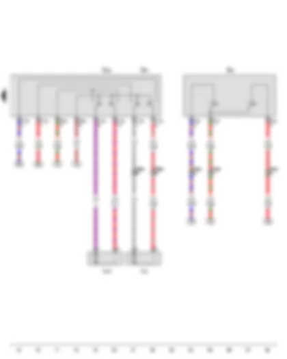
Wiring Diagram AUDI TT 2011 - Driver seat adjustment thermal fuse 1 - Driver seat height adjustment motor - Seat longitudinal adjustment motor


Wiring Diagram  AUDI TT 2011 - Driver seat adjustment thermal fuse 1 - Driver seat height adjustment motor - Seat longitudinal adjustment motor https://portal-diagnostov.com/license.html
https://portal-diagnostov.com/license.html Automotive Electricians Portal FZCO Automotive Electricians Portal FZCO
Download PDF file
E363 Driver seat longitudinal adjustment switch
E364 Driver seat height adjustment switch
SD3 Fuse 3 on fuse holder D
S44 Driver seat adjustment thermal fuse 1, Relay carrier on left under dash panel
T6ac 6-pin connector
T10f 10-pin connector, under driver seat, red
T10g 10-pin connector, under front passenger seat, red
T10s 10-pin connector
V245 Driver seat height adjustment motor
V288 Seat longitudinal adjustment motor
   44 Earth point, lower part of left A-pillar
   95 Earth connection 1, in seat adjustment wiring harness
   376 Earth connection 11, in main wiring harness
   B299 Positive connection 3 (30), in main wiring harness
   B300 Positive connection 4 (30), in main wiring harness
   B322 Positive connection 8 (30a) in main wiring harness
   M1 Positive connection 1 (30), in seat adjustment wiring harness
*Main fuse box, on battery on rear right in luggage compartment

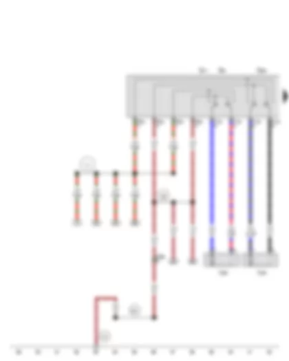
Wiring Diagram AUDI TT 2011 - Driver seat backrest limit switch


Wiring Diagram  AUDI TT 2011 - Driver seat backrest limit switch https://portal-diagnostov.com/license.html
https://portal-diagnostov.com/license.html Automotive Electricians Portal FZCO Automotive Electricians Portal FZCO
Получить доступ ко всем электросхемам автомобиляDownload PDF file
E69 Driver seat backrest limit switch
E96 Driver seat backrest adjustment switch
E222 Driver seat rake adjustment switch
T4ac 4-pin connector, in driver seat
T4af 4-pin connector
T6aa 6-pin connector, in driver seat
T6ac 6-pin connector
T10s 10-pin connector
V45 Driver seat backrest adjustment motor
V243 Driver seat rake adjustment motor

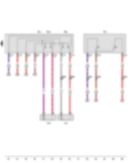
Wiring Diagram AUDI TT 2011 - Front passenger seat adjustment operating unit - Front passenger seat height adjustment motor - Seat longitudinal adjustment motor


Wiring Diagram  AUDI TT 2011 - Front passenger seat adjustment operating unit - Front passenger seat height adjustment motor - Seat longitudinal adjustment motor https://portal-diagnostov.com/license.html
https://portal-diagnostov.com/license.html Automotive Electricians Portal FZCO Automotive Electricians Portal FZCO
Получить доступ ко всем электросхемам автомобиляDownload PDF file
E64 Front passenger seat longitudinal adjustment switch
E365 Front passenger seat height adjustment switch
E471 Front passenger seat adjustment operating unit
T6ac 6-pin connector
T10g 10-pin connector, under front passenger seat, red
T10s 10-pin connector
V246 Front passenger seat height adjustment motor
V288 Seat longitudinal adjustment motor
   43 Earth point, lower part of right A-pillar
   95 Earth connection 1, in seat adjustment wiring harness
   391 Earth connection 26, in main wiring harness
   M1 Positive connection 1 (30), in seat adjustment wiring harness

Wiring Diagram AUDI TT 2011 - Front passenger seat backrest limit switch - Front passenger seat adjustment operating unit


Wiring Diagram  AUDI TT 2011 - Front passenger seat backrest limit switch - Front passenger seat adjustment operating unit https://portal-diagnostov.com/license.html
https://portal-diagnostov.com/license.html Automotive Electricians Portal FZCO Automotive Electricians Portal FZCO
Получить доступ ко всем электросхемам автомобиляDownload PDF file
E70 Front passenger seat backrest limit switch
E98 Front passenger seat backrest adjustment switch
E334 Front passenger seat rake adjustment button
E471 Front passenger seat adjustment operating unit
T4ad 4-pin connector, in front passenger seat
T4ag 4-pin connector
T6ab 6-pin connector, in front passenger seat
T6ac 6-pin connector
T10s 10-pin connector
V46 Front passenger seat backrest adjustment motor
V244 Front passenger seat rake adjustment motor

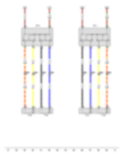
Wiring Diagram AUDI TT 2011 - Driver seat lumbar support adjustment switch - Front passenger seat lumbar support adjustment switch


Wiring Diagram  AUDI TT 2011 - Driver seat lumbar support adjustment switch - Front passenger seat lumbar support adjustment switch https://portal-diagnostov.com/license.html
https://portal-diagnostov.com/license.html Automotive Electricians Portal FZCO Automotive Electricians Portal FZCO
Получить доступ ко всем электросхемам автомобиляDownload PDF file
E176 Driver seat lumbar support adjustment switch
E177 Front passenger seat lumbar support adjustment switch
T6aa 6-pin connector, in driver seat
T6ab 6-pin connector, in front passenger seat
V125 Driver seat lumbar support longitudinal adjustment motor
V126 Front passenger seat lumbar support longitudinal adjustment motor
V129 Driver seat lumbar support height adjustment motor
V130 Front passenger seat lumbar support height adjustment motor


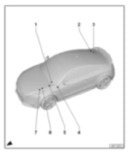
AUDI TT 2011 Overview of fuses

Overview of fuses
AUDI TT 2011 Overview of fuses https://portal-diagnostov.com/license.html
https://portal-diagnostov.com/license.html Automotive Electricians Portal FZCO Automotive Electricians Portal FZCO
Получить доступ ко всем электросхемам автомобиляDownload PDF file
1 -  Fuses on relay carrier behind dash panel
q   Location and position of fuses → chapter
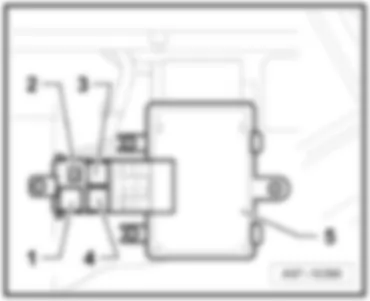
2 -  Main fuse carrier on the battery -A-, fuses (SD)
q   Location and position of fuses → chapter
3 -  Fuses (SF) on fuse holder F
q   Location and position of fuses → chapter
4 -  Fuses (SC) on fuse holder C
q   Location and position of fuses → chapter
5 -  Slave start socket -U6-
q   Location → chapter
6 -  Fuses (SB) on fuse holder B
q   Location and position of fuses → chapter
7 -  Fuses (SA) on fuse holder A
q   Location and position of fuses → chapter


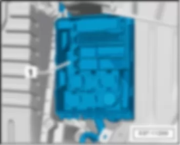
AUDI TT 2011 Fuses (SA) on fuse holder A

Fuses (SA) on fuse holder A
   
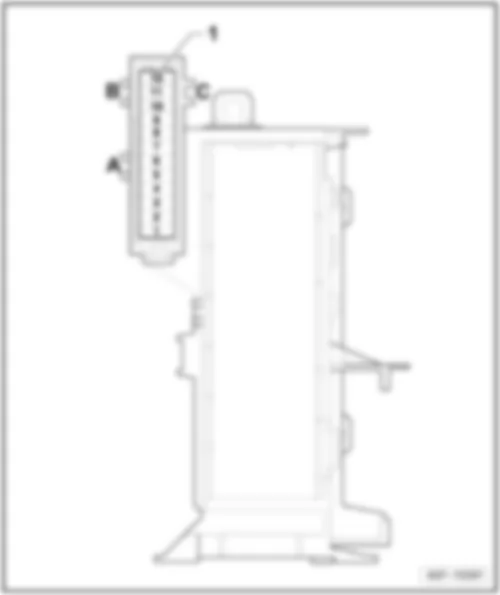
On electronics box, engine compartment -1-.
Fuse colours
40 A -  orange
30 A -  green
25 A -  white
20 A -  yellow
15 A -  blue
10 A -  red
7,5 A -  brown
5 A -  beige
 
AUDI TT 2011 Fuses (SA) on fuse holder A https://portal-diagnostov.com/license.html
https://portal-diagnostov.com/license.html Automotive Electricians Portal FZCO Automotive Electricians Portal FZCO
Получить доступ ко всем электросхемам автомобиляDownload PDF file
AUDI TT 2011 Fuses (SA) on fuse holder A https://portal-diagnostov.com/license.html
https://portal-diagnostov.com/license.html Automotive Electricians Portal FZCO Automotive Electricians Portal FZCO
Получить доступ ко всем электросхемам автомобиляDownload PDF file
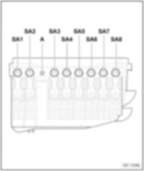
A -  Screw​ connection​ terminal​ 30​ (C)​ of main fuse carrier on the battery -A-
SA -  Fuses on fuse holder A
q   Position of fuses → chapter

Back to overview → chapter.
   
Position of fuses on fuse holder A
No.   Current Flow Diagram designation Nominal value   Function/component Terminal
1 - Fuse 1 on fuse holder A -SA1- 175 A - Alternator -C- 30
2 - Fuse 2 on fuse holder A -SA2- 80 A - Power steering control unit -J500- 30
3 - Fuse 3 on fuse holder A -SA3- 60 A - Radiator fan control unit -J293-
Radiator fan -V7-
30
4 - Fuse 4 on fuse holder A -SA4- 110 A - Supply for fuse carrier in electronics box engine compartment 30
5 - Fuse 5 on fuse holder A -SA5- 40 A - Secondary air pump motor -V101-
Auxiliary air heater heater element -Z35/1-1)
Fuel pump relay -J17-2)
30
6 - Fuse 6 on fuse holder A -SA6- 80 A - Auxiliary air heater heater element -Z35/2-1)
Auxiliary heater element -Z35/3-1)
30
7 - Vacant      
8 - Vacant      

  Note
t  1) engine codes CBBB, CFGB only
t  2) engine codes CEPA, CEPB, CRRA only
Back to overview → chapter.


AUDI TT 2011 Fuses (SB) on fuse holder B

Fuses (SB) on fuse holder B
   
In electronics box, on left in engine compartment -1-.
Fuse colours
40 A -  orange
30 A -  green
25 A -  white
20 A -  yellow
15 A -  blue
10 A -  red
7,5 A -  brown
5 A -  beige
 
AUDI TT 2011 Fuses (SB) on fuse holder B https://portal-diagnostov.com/license.html
https://portal-diagnostov.com/license.html Automotive Electricians Portal FZCO Automotive Electricians Portal FZCO
Получить доступ ко всем электросхемам автомобиляDownload PDF file
AUDI TT 2011 Fuses (SB) on fuse holder B https://portal-diagnostov.com/license.html
https://portal-diagnostov.com/license.html Automotive Electricians Portal FZCO Automotive Electricians Portal FZCO
Получить доступ ко всем электросхемам автомобиляDownload PDF file
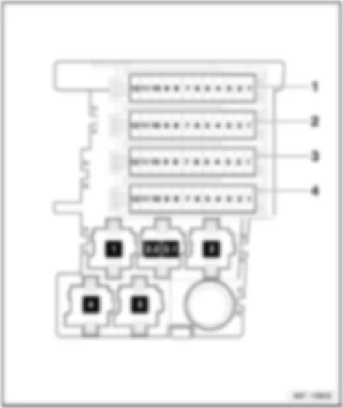
1 -  Fuse carrier ST1, black
q   Position of fuses → chapter
2 -  Fuse carrier ST2, brown
q   Position of fuses → chapter
3 -  Vacant
4 -  Vacant

Back to overview → chapter.
   
Position of fuses on fuse carrier ST1, black
No.   Current Flow Diagram designation Nominal value   Function/component Terminal
1 - Vacant      
2 - Vacant      
3 - Vacant      
4 - Vacant      
5 - Fuse 5 on fuse holder B -SB5- 5 A - Alarm horn -H12-
Anti-theft alarm sensor -G578-
30
6 - Fuse 6 on fuse holder B -SB6- 30 A - Headlight washer system pump -V11- 30
7 - Fuse 7 on fuse holder B -SB7- 15 A
20 A1) 6)
10 A5) 7)
  Fuel pressure regulating valve -N276-1)2)
Fuel system pressurisation pump -G6-4)
Control relay -J789-5) 3)
Supplementary fuel pump -V393-
Engine component current supply relay -J757-6)
30
8 - Fuse 8 on fuse holder B -SB8- 30 A - Wiper motor control unit -J400- 30
9 - Fuse 9 on fuse holder B -SB9- 25 A - Heated seat cushion for front left seat -Z45-
Heated seat cushion for front right seat -Z46-
30
10 - Fuse 10 on fuse holder B -SB10- 10 A - Driver seat lumbar support longitudinal adjustment motor -V125-
Front passenger seat lumbar support longitudinal adjustment motor -V126-
30
11 - Vacant      
12 - Fuse 12 on fuse holder B -SB12- 40 A - Fresh air blower control unit -J126-
fresh air blower -V2-
30

  Note
t  1) engine codes CDAA, CCZA, CCTA only
t  2) engine codes BWA, BPY, CDMA, CDLB, CDLA only
t  3) engine codes CBBB, CFGB only
t  4) engine codes BUB, CBRA only
t  5) engine codes CEPA, CEPB, CRRA only
t  6) engine codes CESA, CETA only
t  7) from June 2011, only 2.0 l diesel engine and 2.0 l petrol engine
Back to overview → chapter.
   
Position of fuses on fuse carrier ST2, brown
No.   Current Flow Diagram designation Nominal value   Function/component Terminal
1 - Fuse 1 on fuse holder B -SB1- 15 A - Fuel system pressurisation pump -G6-4)
Exhaust flap 1 valve -N321-5)
87
2 - Fuse 2 on fuse holder B -SB2- 10 A
30 A5)
- Lambda probe -G39-4)
Lambda probe after catalytic converter -G130-4)
Fuel pump control unit -J538-5)
87
3 - Fuse 3 on fuse holder B -SB3- 5 A - Air mass meter -G70-4) 87
4 - Fuse 4 on fuse holder B -SB4- 10 A - Lambda probe 2 -G108-4)
Lambda probe 2 after catalytic converter -G131-4)
87
5 - Fuse 5 on fuse holder B -SB5- 5 A
10 A5)
- Engine component current supply relay -J757-2)
Automatic glow period control unit -J179-3)
Supplementary fuel pump relay -J832-3)
Fuel pump relay -J17-3)
Lambda probe -G39-5)
87
6 - Fuse 6 on fuse holder B -SB6- 10 A - Fuel system diagnostic pump -V144-4)
Secondary air pump relay -J299-4)
Lambda probe -G39-1) 2) 3) 6)
Lambda probe after catalytic converter -G130-1) 2) 5) 6)
Secondary air inlet valve -N112-4)
Secondary air inlet valve 2 -N320-4)
87
7 - Fuse 7 on fuse holder B -SB7- 10 A - Wastegate solenoid valve -N75-3)
Activated charcoal filter system solenoid valve 1 -N80-4)
Variable intake manifold change-over valve -N156-4)
Camshaft control valve 1 -N205-4)
Exhaust camshaft control valve 1 -N318-4)
Exhaust gas recirculation cooler changeover valve -N345-3)
Radiator fan control unit -J293-1) 3) 4) 5) 6)
Fuel system diagnostic pump -V144-1) 6)
Intake manifold flap valve -N316-6)
87
8 - Fuse 8 on fuse holder B -SB8- 20 A 1) 2) 5) 6)
30 A4)
5 A3)
- Ignition coils -N...-1) 2) 4) 5) 6)
Low heat output relay -J359-3)
High heat output relay -J360-3)
87
9 - Fuse 9 on fuse holder B -SB9- 15 A 1) 6)
25 A2)
30 A3)
25 A4) 5)
- Engine control unit -J623- 87
10 - Fuse 10 on fuse holder B -SB10- 10 A - Continued coolant circulation pump -V51-1)2)4)5)
Continued coolant circulation relay -J151-1) 2) 4) 6)
Exhaust gas recirculation cooler pump -V400-3)
Coolant circulation solenoid valve -N492-5)
Additional coolant pump relay -J496-5)
87
11 - Fuse 11 on fuse holder B -SB11- 5 A - Clutch position sender -G476- 87
12 - Fuse 12 on fuse holder B -SB12- 10 A
20 A3)
- Engine component current supply relay -J757-1) 6)
Activated charcoal filter system solenoid valve 1 -N80-1 )2) 6)
Charge pressure control solenoid valve -N75-1) 2) 6)
Camshaft control valve 1 -N205-1) 6)
Turbocharger air recirculation valve -N249-1) 2) 6)
Fuel pressure regulating valve -N276-3)
Fuel metering valve -N290-3)
Intake manifold flap valve -N316-1)
Oil pressure control valve -N428-1) 6)
Secondary air inlet valve -N112-6)
Actuator 1 for camshaft adjustment -F366-6)
87

  Note
t  1) engine codes CDAA, CCZA, CCTA only
t  2) engine codes BWA, BPY, CDMA, CDLA, CDLB only
t  3) engine codes CBBB, CFGB only
t  4) engine codes BUB, CBRA only
t  5) engine codes CEPA, CEPB, CRRA only
t  6) engine codes CESA, CETA only
Back to overview → chapter.


AUDI TT 2011 Fuses (SC) on fuse holder C

Fuses (SC) on fuse holder C
   
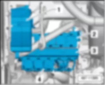
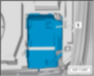
Left-hand drive: at left of dash panel -1-
1 -  fuse holder C
2 -  Relay carrier behind dash panel
3 -  onboard supply control unit -J519-
4 -  Relay carrier on onboard supply control unit -J519-, from June 2009
 
AUDI TT 2011 Fuses (SC) on fuse holder C https://portal-diagnostov.com/license.html
https://portal-diagnostov.com/license.html Automotive Electricians Portal FZCO Automotive Electricians Portal FZCO
Получить доступ ко всем электросхемам автомобиляDownload PDF file
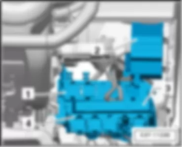
Right-hand drive: at right of dash panel -2-.
1 -  Relay carrier behind dash panel
2 -  fuse holder C
3 -  onboard supply control unit -J519-
4 -  Relay carrier on onboard supply control unit -J519-, from June 2009
Fuse colours
40 A -  orange
30 A -  green
25 A -  white
20 A -  yellow
15 A -  blue
10 A -  red
7,5 A -  brown
5 A -  beige
 
AUDI TT 2011 Fuses (SC) on fuse holder C https://portal-diagnostov.com/license.html
https://portal-diagnostov.com/license.html Automotive Electricians Portal FZCO Automotive Electricians Portal FZCO
Получить доступ ко всем электросхемам автомобиляDownload PDF file
Fuse locations
 
AUDI TT 2011 Fuses (SC) on fuse holder C https://portal-diagnostov.com/license.html
https://portal-diagnostov.com/license.html Automotive Electricians Portal FZCO Automotive Electricians Portal FZCO
Получить доступ ко всем электросхемам автомобиляDownload PDF file
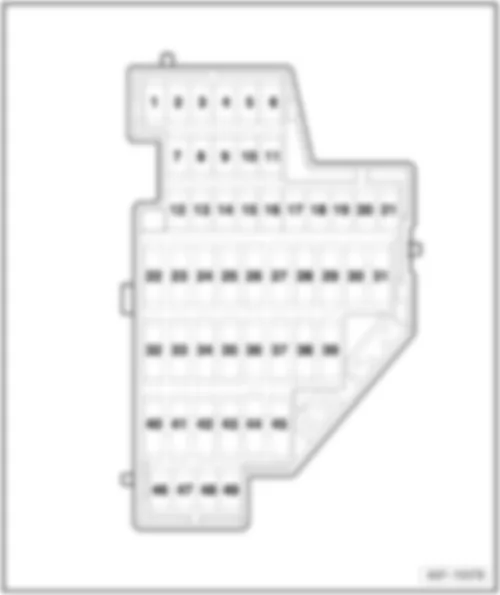
No.   Current Flow Diagram designation Nominal value   Function/component Terminal
1 - Fuse 1 on fuse holder C -SC1- 10 A - Fuel pump relay -J17-
Electric fuel pump 2 relay -J49-1)
Fuel pump control unit -J538-
Engine control unit -J623-
Front passenger front airbag deactivated warning lamp -K145-
Light switch illumination bulb -L9-
16-pin connector, diagnostic connector -T16-
15
2 - Fuse 2 on fuse holder C -SC2- 5 A - ABS control unit -J104-
Brake light switch -F-
15
3 - Fuse 3 on fuse holder C -SC3- 5 A - Output module for left headlight -J667- 15
4 - Fuse 4 on fuse holder C -SC4- 5 A - Oil level and oil temperature sender -G266-
Tyre pressure monitor button -E226-
Tyre pressure monitor control unit 2 -J793-
TCS and ESP button -E256-
Headlight range control, control unit -J431-
High-pressure sender -G65-
Reversing light switch -F4-
15
5 - Fuse 5 on fuse holder C -SC5- 10 A5)
5 A6)
- Right headlight range control motor -V49-5)
Left headlight range control motor -V48-5)
Headlight range control adjuster -E102-5)
Control unit for headlight range control -J431-6)
Power output module for right headlight -J668-6)
15
6 - Fuse 6 on fuse holder C -SC6- 5 A - Power steering control unit -J500-
Data bus diagnostic interface -J533-
Selector lever sensors control unit -J587-
Mechatronic unit for dual clutch gearbox -J743-
15
7 - Fuse 7 on fuse holder C -SC7- 5 A - Control unit for parking aid -J446-
Automatic anti-dazzle interior mirror -Y7-
Garage door operating unit -E284-
Garage door operation control unit -J530-
Left washer jet heater element -Z20-
Right washer jet heater element -Z21-
onboard supply control unit -J519-
Washer pump relay -J576-
Cabrio windbreak control unit -J531-
15
8 - Fuse 8 on fuse holder C -SC8- 5 A
10 A2)
- All-wheel drive control unit -J492- 15
9 - Fuse 9 on fuse holder C -SC9- 5 A - Electronically controlled damping control unit -J250- 15
10 - Fuse 10 on fuse holder C -SC10- 5 A - Airbag control unit -J234-
Seat occupied recognition control unit -J706-7)
15
11 - Fuse 11 on fuse holder C -SC11- 10 A1)4)
5 A3)
- Air mass meter -G70-3) 4)
Structure-borne noise control unit -J869-4)
Crankcase breather heater element -N79-1) 4)
15
12 - Fuse 12 on fuse holder C -SC12- 10 A - Driver door control unit -J386-
Front passenger door control unit -J387-
30
13 - Fuse 13 on fuse holder C -SC13- 10 A - 16-pin connector -T16-, diagnostic connector 30
14 - Fuse 14 on fuse holder C -SC14- 5 A
15 A15)
- Light/rain sensor -G397-12)
Selector lever sensors control unit -J587-14)
Mechatronic unit for dual clutch gearbox -J743-15)
30
15 - Fuse 15 on fuse holder C -SC15- 5 A
15 A13)
- onboard supply control unit -J519-
Front interior light -W1-
Light/rain sensor -G397-13)
30
16 - Fuse 16 on fuse holder C -SC16- 10 A - Climatronic control unit -J255- 30
17 - Fuse 17 on fuse holder C -SC17- 5 A - Tyre pressure monitor control unit -J502-7)
Tyre pressure monitor control unit 2 -J793-
Selector lever sensors control unit -J587-15)
30
18 - Vacant      
19 - Vacant      
20 - Vacant      
21 - Fuse 21 on fuse holder C -SC21- 10 A - Injectors -N....-1) 15
22 - Fuse 22 on fuse holder C -SC22- 30 A - Cabrio windbreak control unit -J531-9) 30
23 - Fuse 23 on fuse holder C -SC23- 20 A - High tone horn -H2-
Low tone horn -H7-
30
24 - Fuse 24 on fuse holder C -SC24- 15 A
30 A15)
- Mechatronic unit for dual clutch gearbox -J743- 30
25 - Fuse 25 on fuse holder C -SC25- 30 A
20 A9)
- Heated rear window -Z1- 30
26 - Fuse 26 on fuse holder C -SC26- 30 A - Driver side window regulator motor -V147- 30
27 - Fuse 27 on fuse holder C -SC27- 30 A - Front passenger side window regulator motor -V148- 30
28 - Vacant      
29 - Fuse 29 on fuse holder C -SC29- 15 A - Washer pump -V5- 15
30 - Fuse 30 on fuse holder C -SC30- 20 A - Cigarette lighter -U1-10)
12-V plug socket -U5-7) 10)
15
31   Fuse 31 on fuse holder C -SC31- 40 A - Starter -B-
Terminal 50 voltage supply relay -J682-
15
32   Fuse 32 on fuse holder C -SC32- 5 A - Steering column electronics control unit -J527- 30
33   Fuse 33 on fuse holder C -SC33- 5 A - Control unit in dash panel insert -J285- 30
34   Fuse 34 on fuse holder C -SC34- 15 A
20 A8)
- Navigation system with CD drive control unit -J401-
Radio -R-
Control unit with display for radio and navigation -J503-
30
35   Fuse 35 on fuse holder C -SC35- 30 A - Digital sound package control unit -J525- 30
36   Fuse 36 on fuse holder C -SC36- 10 A - Engine control unit -J623-
Motronic current supply relay -J271-
Terminal 30 voltage supply relay -J317-4)
Fuel pump relay -J17-16)
30
37 - Fuse 37 on fuse holder C -SC37- 5 A - Data bus diagnostic interface -J533- 30
38 - Fuse 38 on fuse holder C -SC38- 20 A - Relay for power sockets -J807-11)
Cigarette lighter -U1-11)
12-V plug socket -U5-7) 11)
30
39 - Vacant      
40 - Vacant      
41 - Vacant      
42 - Vacant      
43 - Vacant      
44 - Vacant      
45 - Vacant      
46 - Vacant      
47 - Fuse 47 on fuse holder C -SC47- 5 A - Satellite radio -R146-7)
Telephone transmitter and receiver unit -R36-
Aerial amplifier for mobile telephone -R86-
30
      7.5 A - TV tuner -R78-
Preparation for mobile telephone
30
48 - Fuse 48 on fuse holder C -SC48- 5 A - Preparation for mobile telephone 15
49 - Vacant      

  Note
t  1) engine codes BUB, CBRA only
t  2) engine codes CDLB, CDLA only
t  3) engine codes BWA, BPY, CDMA, CDLA, CDLB only
t  4) engine codes CBBB, CFGB
t  5) for manual headlight range control
t  6) for automatic headlight range control
t  7) for models with US equipment only
t  8) for models with Japan equipment only
t  9) Roadster
t  10) up to May 2007
t  11) from June 2007
t  12) up to May 2009
t  13) from June 2009
t  14) for models with DQ500 7-speed dual clutch gearbox OBH (S tronic) only
t  15) for models with DQ200 7-speed dual clutch gearbox OAM (S tronic) only
t  16) engine codes CEPA, CEPB, CRRA only
Back to overview → chapter.


AUDI TT 2011 Fuses (SF) on fuse holder F

Fuses (SF) on fuse holder F
   
In luggage compartment, rear right -1-.
Fuse colours
40 A -  orange
30 A -  green
25 A -  white
20 A -  yellow
15 A -  blue
10 A -  red
7,5 A -  brown
5 A -  beige
 
AUDI TT 2011 Fuses (SF) on fuse holder F https://portal-diagnostov.com/license.html
https://portal-diagnostov.com/license.html Automotive Electricians Portal FZCO Automotive Electricians Portal FZCO
Получить доступ ко всем электросхемам автомобиляDownload PDF file
AUDI TT 2011 Fuses (SF) on fuse holder F https://portal-diagnostov.com/license.html
https://portal-diagnostov.com/license.html Automotive Electricians Portal FZCO Automotive Electricians Portal FZCO
Получить доступ ко всем электросхемам автомобиляDownload PDF file
A -  Vacant
B -  Vacant
C -  Vacant
1 -  Fuse holder F
q   Position of fuses → chapter

Back to overview → chapter.
   
Fuse assignment on fuse holder F
No.   Current Flow Diagram designation Nominal value   Function/component Terminal
1 - Fuse 1 on fuse holder F -SF1- 5 A - onboard supply control unit -J519-, reference voltage 30
2 - Fuse 2 on fuse holder F -SF2- 40 A - onboard supply control unit -J519- 30
3 - Vacant      
4 - Fuse 4 on fuse holder F -SF4- 30 A - Convertible roof actuation control unit -J256-1)
Convertible roof actuation hydraulic pump -V118-1)
30
5 - Fuse 5 on fuse holder F -SF5- 5 A - Control unit for parking aid -J446-
Interface for special functions 2)
30
6 - Fuse 6 on fuse holder F -SF6- 15 A - Fuel pump control unit -J538-3)4)
Fuel system pressurisation pump -G6-5)
30
7 - Fuse 7 on fuse holder F -SF7- 40 A - onboard supply control unit -J519- 30
8 - Fuse 8 on fuse holder F -SF8- 20 A - ABS control unit -J104-, ABS valves 30
9 - Fuse 9 on fuse holder F -SF9- 30 A - Electronically controlled damping control unit -J250- 30
10 - Fuse 10 on fuse holder F -SF10- 20 A 6)
10 A 7)
- Convenience system central control unit -J393-6)
Onboard supply control unit -J519-7)
30
11 - Fuse 11 on fuse holder F -SF11- 25 A - Convertible roof actuation control unit -J256-1) 30
12 - Fuse 12 on fuse holder F -SF12- 5 A6) - Convenience system central control unit -J393-6) 30

  Note
t  1) Roadster
t  2) from June 2007
t  3) engine codes CDAA, CCZA, CCTA only
t  4) engine codes BWA, BPY, CDMA, CDLA, CDLB only
t  5) engine codes CBBB, CFGB only
t  6) up to May 2009
t  7) from June 2009
Back to overview → chapter.


AUDI TT 2011 Fuses (SD) on main fuse carrier

Fuses (SD) on main fuse carrier
   
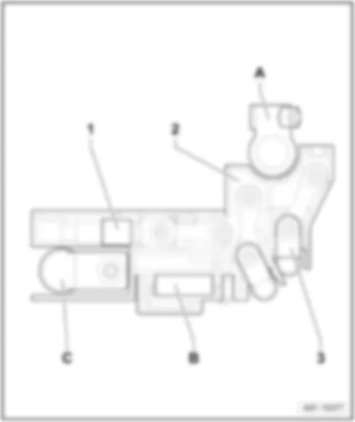
In luggage compartment, on the battery -A--1- .
 
AUDI TT 2011 Fuses (SD) on main fuse carrier https://portal-diagnostov.com/license.html
https://portal-diagnostov.com/license.html Automotive Electricians Portal FZCO Automotive Electricians Portal FZCO
Получить доступ ко всем электросхемам автомобиляDownload PDF file
AUDI TT 2011 Fuses (SD) on main fuse carrier https://portal-diagnostov.com/license.html
https://portal-diagnostov.com/license.html Automotive Electricians Portal FZCO Automotive Electricians Portal FZCO
Получить доступ ко всем электросхемам автомобиляDownload PDF file
A -  Connection battery positive
B -  Battery isolation igniter -N253-
C -  Wire to fuse holder A
C -  Cable to starter -B-
1 -  Fuse 1 on fuse holder D -SD1-, 40 A, to ABS hydraulic pump -V64-
2 -  Fuse 2 on fuse holder D -SD2-, 110 A, to fuse holder F
3 -  Fuse 3 on fuse holder D -SD3-, 110 A, to fuse holder C

Back to overview → chapter.


AUDI TT 2011 Fuses on relay carrier behind dash panel

Fuses on relay carrier behind dash panel
   
Left-hand drive: at left of dash panel -2-.
1 -  fuse holder C
2 -  Relay carrier behind left of dash panel
3 -  onboard supply control unit -J519-
4 -  Relay carrier on onboard supply control unit -J519-, from June 2009
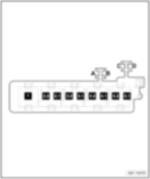
Position of fuses, left-hand drive
 
AUDI TT 2011 Fuses on relay carrier behind dash panel https://portal-diagnostov.com/license.html
https://portal-diagnostov.com/license.html Automotive Electricians Portal FZCO Automotive Electricians Portal FZCO
Получить доступ ко всем электросхемам автомобиляDownload PDF file
AUDI TT 2011 Fuses on relay carrier behind dash panel https://portal-diagnostov.com/license.html
https://portal-diagnostov.com/license.html Automotive Electricians Portal FZCO Automotive Electricians Portal FZCO
Получить доступ ко всем электросхемам автомобиляDownload PDF file
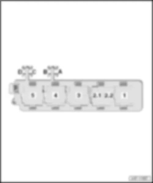
A -  Vacant
B -  Vacant
C -  Driver seat adjustment thermal fuse 1 -S44-, 20 A
D -  Vacant

   
Right-hand drive: at right behind dash panel -1-.
1 -  Relay carrier behind right of dash panel
2 -  fuse holder C
3 -  onboard supply control unit -J519-
4 -  Relay carrier on onboard supply control unit -J519- from June 2009
Position of fuses, right-hand drive
 
AUDI TT 2011 Fuses on relay carrier behind dash panel https://portal-diagnostov.com/license.html
https://portal-diagnostov.com/license.html Automotive Electricians Portal FZCO Automotive Electricians Portal FZCO
Получить доступ ко всем электросхемам автомобиляDownload PDF file
AUDI TT 2011 Fuses on relay carrier behind dash panel https://portal-diagnostov.com/license.html
https://portal-diagnostov.com/license.html Automotive Electricians Portal FZCO Automotive Electricians Portal FZCO
Получить доступ ко всем электросхемам автомобиляDownload PDF file
A -  Vacant
B -  Vacant
C -  Driver seat adjustment thermal fuse 1 -S44-, 20 A
D -  Vacant

Back to overview → chapter.


AUDI TT 2011 Slave start socket U6

Slave start socket -U6-
Location:
in rear left of engine compartment.
   
AUDI TT 2011 Slave start socket U6 https://portal-diagnostov.com/license.html
https://portal-diagnostov.com/license.html Automotive Electricians Portal FZCO Automotive Electricians Portal FZCO
Получить доступ ко всем электросхемам автомобиляDownload PDF file
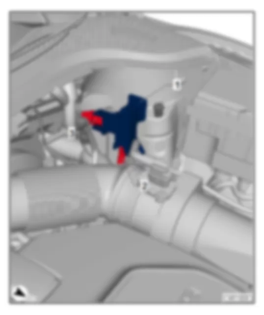
1 -  Slave start socket -U6- (positive)
2 -  Cable to fuse holder A in electronics box, engine compartment
3 -  Cable to main fuse carrier on the battery -A-

Back to overview → chapter.


AUDI TT 2011 Overview of coupling stations and connectors

Overview of coupling stations and connectors
AUDI TT 2011 Overview of coupling stations and connectors https://portal-diagnostov.com/license.html
https://portal-diagnostov.com/license.html Automotive Electricians Portal FZCO Automotive Electricians Portal FZCO
Получить доступ ко всем электросхемам автомобиляDownload PDF file
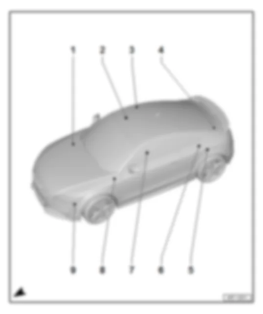
1 -  Coupling station on right of dash panel, glove compartment
q   Connector -T8k-
q   Location → chapter
2 -  Coupling station under right front seat
q   Connectors-T10i-, -T3d-, -T6e-, -T10g-
q   Location → chapter
3 -  Coupling station on right of rear lid, in rear right roof frame
q   Connectors-T2f-, -T2e-, -T2d-, -T2c-
q   Location → chapter
4 -  Coupling station on left of rear lid, Roadster
q   Connectors-T6f-, -T8e-
q   Location → chapter
5 -  Coupling station in left side panel, Roadster
q   Connector -T10c-
q   Location → chapter
6 -  Coupling station on left of rear lid, behind side panel, Coupé
q   Connectors-T6f-, -T8e-
q   Location → chapter
7 -  Coupling station under left front seat
q   Connectors-T10f-, -T10h-, -T3c-, -T6d-
q   Location → chapter
8 -  Diagnostic connection
q   Connector -T16-
q   Location → chapter
9 -  Coupling station left in engine compartment
q   Connector -T14-
q   Location → chapter


AUDI TT 2011 Coupling station under left front seat

Coupling station under left front seat
Fitting location
Under front left seat
   
Connectors:
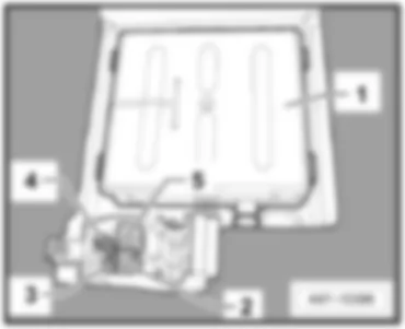
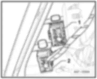
1 -  Telephone transmitter and receiver unit -R36-
2 -  10-pin connector -T10f-, red
3 -  10-pin connector -T10h-, black
4 -  3-pin connector -T3c-, yellow
5 -  6-pin, connector -T6d-, green
Back to overview → chapter.


AUDI TT 2011 Coupling station under right front seat

Coupling station under right front seat
Fitting location
Under front right seat.
 
AUDI TT 2011 Coupling station under right front seat https://portal-diagnostov.com/license.html
https://portal-diagnostov.com/license.html Automotive Electricians Portal FZCO Automotive Electricians Portal FZCO
Получить доступ ко всем электросхемам автомобиляDownload PDF file
Connectors:
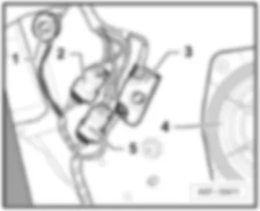
1 -  10-pin connector -T10i-, black
2 -  3-pin connector -T3d-, yellow
3 -  6-pin, connector -T6e-, green
4 -  10-pin connector -T10g-, red
5 -  Electronically controlled damping control unit -J250-
Back to overview → chapter.


AUDI TT 2011 Coupling station right rear lid, in rear right roof frame

Coupling station right rear lid, in rear right roof frame
Fitting location
Behind the roof trim, upper right.
 
AUDI TT 2011 Coupling station right rear lid, in rear right roof frame https://portal-diagnostov.com/license.html
https://portal-diagnostov.com/license.html Automotive Electricians Portal FZCO Automotive Electricians Portal FZCO
Получить доступ ко всем электросхемам автомобиляDownload PDF file
Connectors:
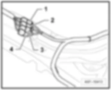
1 -  2-pin connector -T2f-, blue, GPS
2 -  2-pin connector -T2e-, yellow, ZF/HF2
3 -  2-pin connector -T2d-, white, HF1
4 -  2-pin connector -T2c-, black, DAB
Back to overview → chapter.


AUDI TT 2011 Coupling station on left of rear lid, Roadster

Coupling station on left of rear lid, Roadster
Fitting location
behind side trim on left.
 
AUDI TT 2011 Coupling station on left of rear lid, Roadster https://portal-diagnostov.com/license.html
https://portal-diagnostov.com/license.html Automotive Electricians Portal FZCO Automotive Electricians Portal FZCO
Получить доступ ко всем электросхемам автомобиляDownload PDF file
Connectors:
1 -  8-pin connector -T8e-, brown
2 -  6-pin, connector -T6f-, black
Back to overview → chapter.


AUDI TT 2011 Coupling station on left of rear lid, behind side panel, CoupГ©

Coupling station on left of rear lid, behind side panel, Coupé
Fitting location
behind side trim on left.
 
AUDI TT 2011 Coupling station on left of rear lid, behind side panel, CoupГ© https://portal-diagnostov.com/license.html
https://portal-diagnostov.com/license.html Automotive Electricians Portal FZCO Automotive Electricians Portal FZCO
Получить доступ ко всем электросхемам автомобиляDownload PDF file
Connectors:
1 -  662 Earth point, rear left side panel
2 -  6-pin, connector -T6f-, black
3 -  Window aerial suppression filter -C18-
4 -  Rear left mid-range and bass loudspeaker -R159-
5 -  8-pin connector -T8e-, brown
Back to overview → chapter.


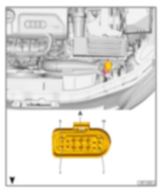
AUDI TT 2011 Coupling station left in engine compartment

Coupling station left in engine compartment
Fitting location
in engine compartment, at front of left longitudinal member.
Connector
 
AUDI TT 2011 Coupling station left in engine compartment https://portal-diagnostov.com/license.html
https://portal-diagnostov.com/license.html Automotive Electricians Portal FZCO Automotive Electricians Portal FZCO
Получить доступ ко всем электросхемам автомобиляDownload PDF file
AUDI TT 2011 Coupling station left in engine compartment https://portal-diagnostov.com/license.html
https://portal-diagnostov.com/license.html Automotive Electricians Portal FZCO Automotive Electricians Portal FZCO
Получить доступ ко всем электросхемам автомобиляDownload PDF file
A -  14-pin connector -T14-, black

Back to overview → chapter.


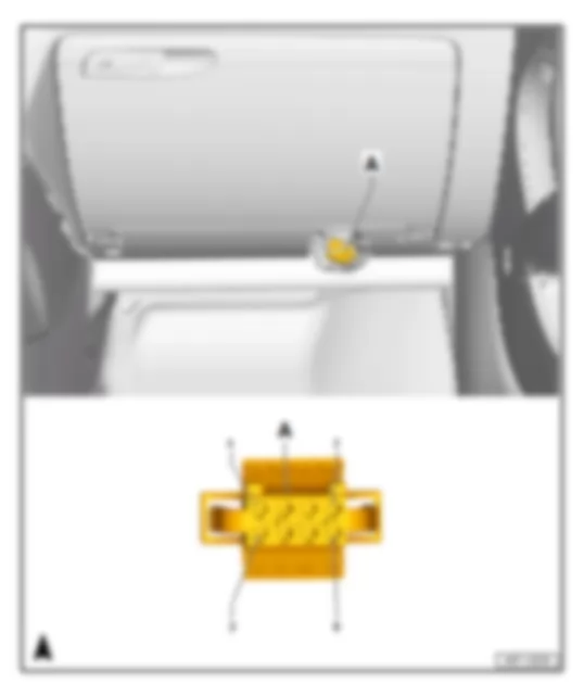
AUDI TT 2011 Coupling station on right of dash panel, glove compartment

Coupling station on right of dash panel, glove compartment
Fitting location
Behind glove compartment at right.
Connector
   
AUDI TT 2011 Coupling station on right of dash panel, glove compartment https://portal-diagnostov.com/license.html
https://portal-diagnostov.com/license.html Automotive Electricians Portal FZCO Automotive Electricians Portal FZCO
Получить доступ ко всем электросхемам автомобиляDownload PDF file
A -  8-pin connector -T8k-, black

Back to overview → chapter.


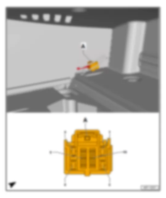
AUDI TT 2011 Coupling station in left side panel, Roadster

Coupling station in left side panel, Roadster
Fitting location
behind left luggage compartment side trim.
Connector
   
AUDI TT 2011 Coupling station in left side panel, Roadster https://portal-diagnostov.com/license.html
https://portal-diagnostov.com/license.html Automotive Electricians Portal FZCO Automotive Electricians Portal FZCO
Получить доступ ко всем электросхемам автомобиляDownload PDF file
A -  10-pin connector -T10c-, black

Back to overview → chapter.


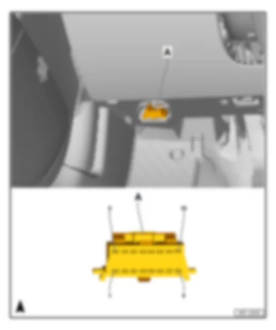
AUDI TT 2011 Diagnostic connection

Diagnostic connection
Fitting location
under the shelf on the driver's side
Connector
   
AUDI TT 2011 Diagnostic connection https://portal-diagnostov.com/license.html
https://portal-diagnostov.com/license.html Automotive Electricians Portal FZCO Automotive Electricians Portal FZCO
Получить доступ ко всем электросхемам автомобиляDownload PDF file
A -  16-pin connector -T16-, black

Back to overview → chapter.