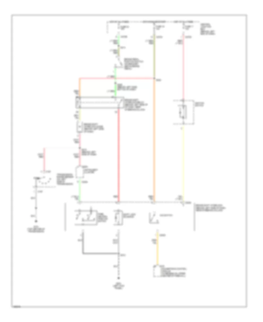
SHIFT INTERLOCKS
Shift Interlock Wiring Diagram for Ford Escape 2002
List of elements for Shift Interlock Wiring Diagram for Ford Escape 2002:
- Brake pedal position switch (on bracket above brake pedal)
- Brake shift interlock diode (behind left side of dash)
- Brake shift interlock (behind left side of dash, near steering column)
- Brake shift interlock relay (behind left side of of dash, near steering column)
- C167
- C175
- C2008
- C220b
- C270c
- C270d
- C270e
- Central junction box (behind left end of dash)
- Fuse 11 10a
- Fuse 16 10a
- Fuse 24 15a
- G101 (top center of transmission)
- G203 (left kick panel)
- Hot at all times
- Hot in run or start
- Ignition switch
- Instrument cluster
- O/d switch
- Park
- Park neutral position switch
- Powertrain control module (in recess on upper center of firewall)
- Red
- S212
- S218 (behind left side of dash)
- S222
- S226 (behind left side, bottom of dash)
- S314
- Shift lock solenoid
- Transmission range sensor (on left side of transmission)
 Русский