
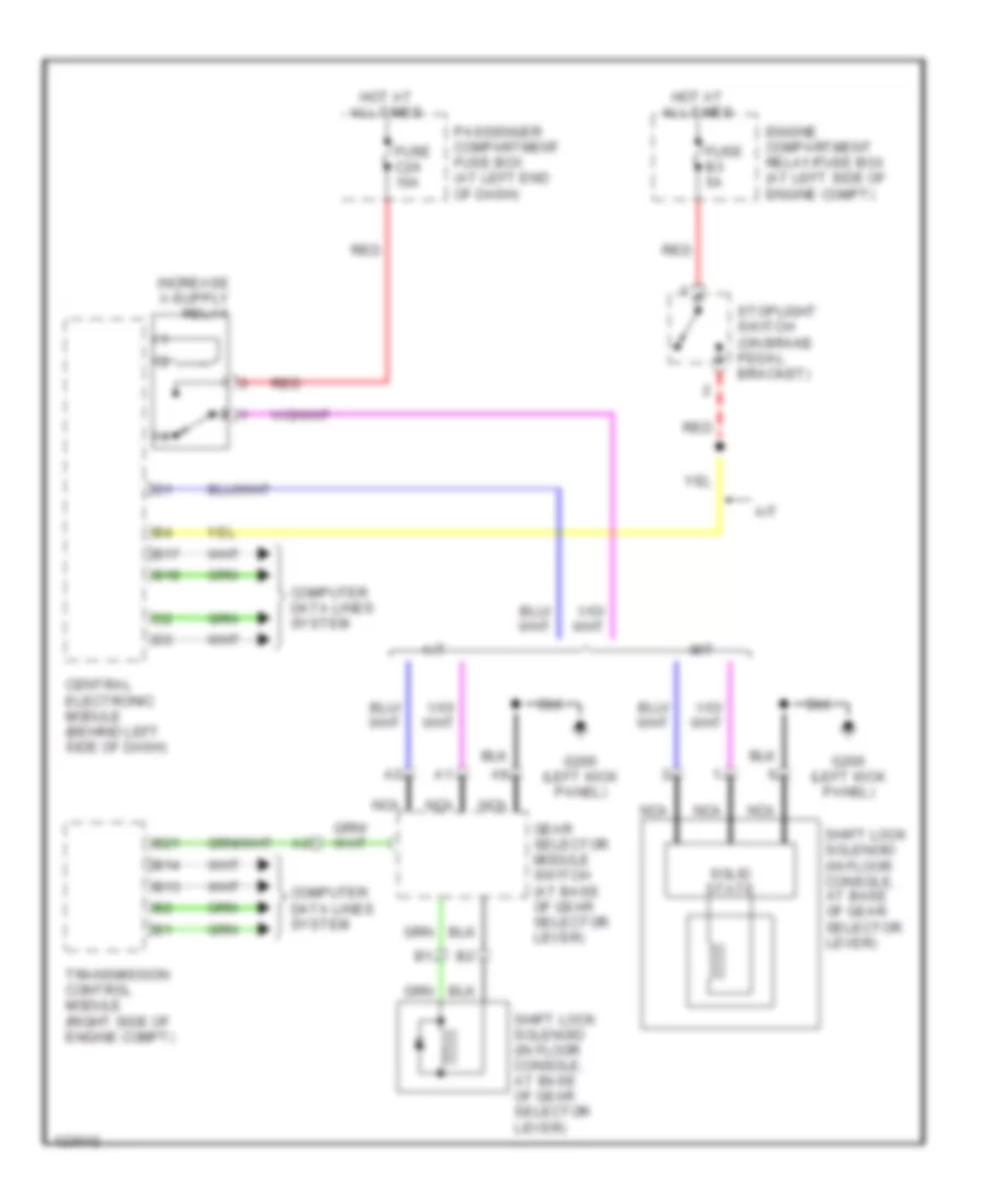
SHIFT INTERLOCKS
Shift Interlock Wiring Diagram for Volvo S80 T-6 2000
List of elements for Shift Interlock Wiring Diagram for Volvo S80 T-6 2000:
AIR CONDITIONINGBODY COMPUTERCOMPUTER DATA LINESCOOLING FANCRUISE CONTROLELECTRONIC POWER STEERINGENGINE PERFORMANCEGROUND DISTRIBUTIONDEFOGGERSHEADLIGHTSINTERIOR LIGHTSEXTERIOR LIGHTSHORNMEMORY SYSTEMSNAVIGATIONPOWER DOOR LOCKSPOWER SEATSPOWER MIRRORSPOWER DISTRIBUTIONPOWER WINDOWSSTARTING/CHARGINGPOWER TOP/SUNROOFSHIFT INTERLOCKSRADIOSUPPLEMENTAL RESTRAINTSTRANSMISSIONWARNING SYSTEMSWIPER/WASHERANTI-THEFTANTI-LOCK BRAKESINSTRUMENT CLUSTER