
SHIFT INTERLOCKS
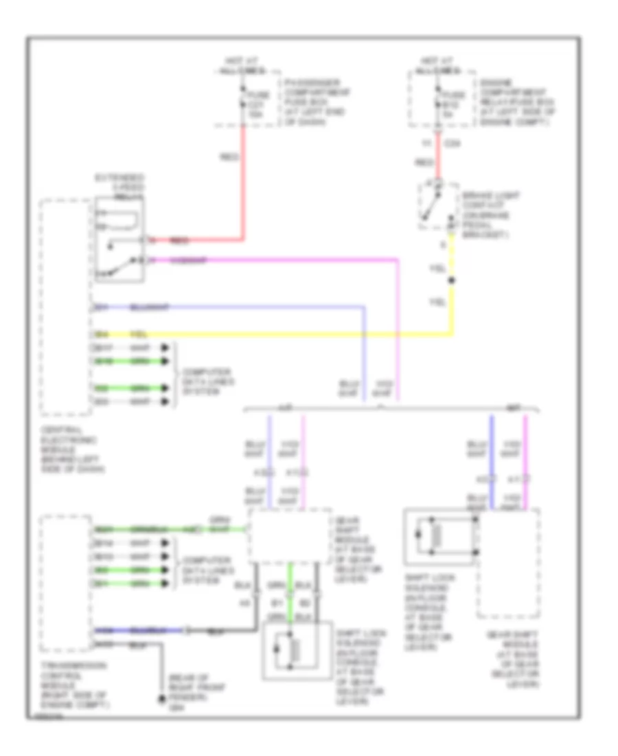
Shift Interlock Wiring Diagram for Volvo V70 T-5 2002
List of elements for Shift Interlock Wiring Diagram for Volvo V70 T-5 2002:
ANTI-THEFTAIR CONDITIONINGBODY COMPUTERANTI-LOCK BRAKESELECTRONIC POWER STEERINGEXTERIOR LIGHTSCOMPUTER DATA LINESENGINE PERFORMANCECRUISE CONTROLGROUND DISTRIBUTIONDEFOGGERSHORNCOOLING FANPOWER DOOR LOCKSHEADLIGHTSINTERIOR LIGHTSINSTRUMENT CLUSTERPOWER TOP/SUNROOFNAVIGATIONPOWER SEATSPOWER MIRRORSPOWER WINDOWSMEMORY SYSTEMSSHIFT INTERLOCKSPOWER DISTRIBUTIONRADIOSUPPLEMENTAL RESTRAINTSSTARTING/CHARGINGTRANSMISSIONWARNING SYSTEMSWIPER/WASHER