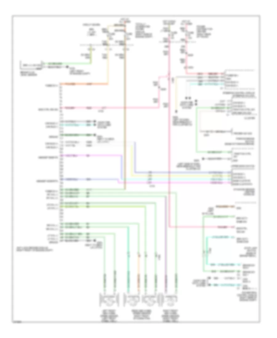
ANTI-LOCK BRAKES
Anti-lock Brakes Wiring Diagram for Chrysler 300 SRT-8 2010
List of elements for Anti-lock Brakes Wiring Diagram for Chrysler 300 SRT-8 2010:
- (left side of dash, near breakout for cluster c3)
- 29b
- 30b
- A107
- A111
- A913
- Abs/esp snsr fd
- Abs/esp snsr rtn
- Anti-lock brakes module (right front of engine compt)
- B15
- B16
- Brake fluid level sensor
- Brake sw sig 1
- Brake sw sig 2
- Brk actv
- Brk lvl sw sig
- C102
- C104
- C203
- Can bus (+)
- Can bus (-)
- Circuit board
- Cluster
- Computer data lines system
- D464
- D465
- D64
- D65
- Dynamics sensor (center console)
- Eng ctrl
- Eng ctrl r/s ign
- F202
- Fuse
- Fuse 10a
- Fuse 30a
- Fuse 50a
- Fused b (+)
- Fused b(+)
- G100 (left front of engine compt)
- G200
- G202 (left of dash, near breakout for cluster c3)
- G300 (left "b" pillar)
- G304 (next to deck lid latch)
- G94
- Gnd
- Ground
- Hot at all times
- Hot in run or start
- Left front abs wheel speed sensor (left front wheel well)
- Lf whl (-)
- Lr whl (+)
- Lr whl (-)
- Parking brake switch (base of parking brake)
- Power distribution center (right rear of trunk)
- Powertrain control module (right rear of engine compt)
- Prk brk sw sig
- Rear abs wheel speed sensor (right front of cargo pan)
- Red
- Rf whl (+)
- Rf whl (-)
- Right front abs wheel speed sensor (right front wheel well)
- Ris ign
- Rr whl (+)
- Rr whl (-)
- S209
- S309
- Snse sig
- Snse sig2
- Snsr clstr fd
- Snsr clstr rtn
- Steering control module (steering column)
- Stop lamp
- Switch (base of brake pedal)
- Tan/ red
- Tan/red
- Totally integrated power module (right side of engine compt)
- Traction ctrl sw
- Upper bank switch
- Z910
- Z931
 Čeština
 Dansk
Dansk Deutsch
 Ελληνικά
 English
 English
 Español
 Suomi
Suomi Français
 Français
 עברית
עברית Hrvatski
 Magyar
 Italiano
 日本語
日本語 한국어
한국어 Nederlands
 Polski
 Português
 Português
 Română
 Русский
 Slovenščina
 Svenska
 Türkçe
 中文 (中国)
 Slovenčina