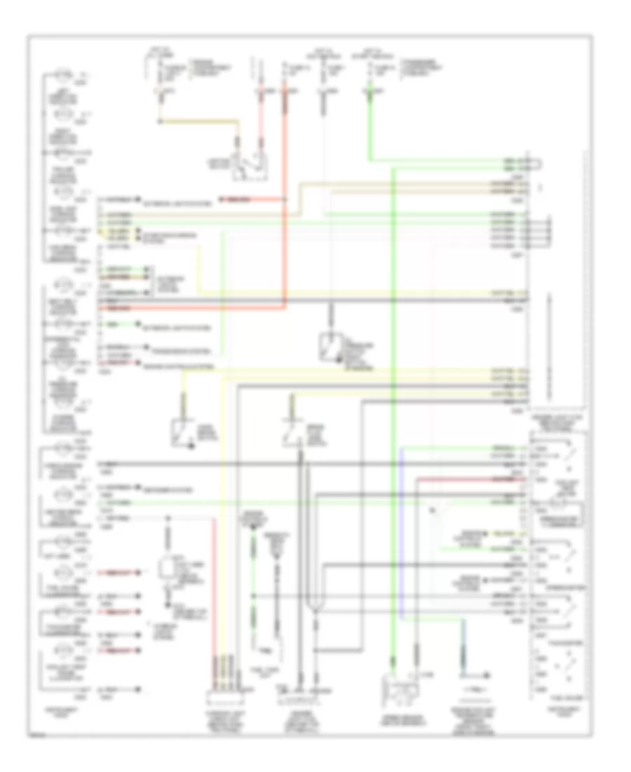
INSTRUMENT CLUSTER
Instrument Cluster Wiring Diagram for Land Rover Defender 90 1997
List of elements for Instrument Cluster Wiring Diagram for Land Rover Defender 90 1997:
- (beneath gear box) g113
- Brake fluid level switch
- C195
- C218
- C219
- C230
- C233
- C269
- C285
- C287
- C288
- C289
- C550
- C580 red
- C842
- C860
- C928
- C929
- C932
- C935
- C936
- C937
- C938
- C939
- C940
- C943
- Charge warning indicator
- Check engine warning indicator
- Coolant temp gauge
- Coolant temp gauge illumination
- Defogger system
- Differential lock warning indicator
- Engine compartment fuse box
- Engine controls system
- Engine coolant temperature sensor (front right side of engine)
- Exterior lights system
- Fuel gauge
- Fuel gauge illumination
- Fuel tank unit
- Fuse 1 15a
- Fuse 12 5a
- Fuse 18 15a
- Fusible link 4 30a
- G121
- G121 (center top of firewall)
- Hand- brake switch
- Header joint k108 (center top of firewall)
- Header joint k109 (behind dash trim panel)
- Heated rear window indicator
- High beam warning indicator
- Hot at all times
- Hot in acc and run
- Hot in start and run
- Instrument pack
- Interior lights system
- Left direction indicator
- Lighting switch
- Not used
- Not used v101 (above gearbox)
- Oil pressure switch (right bottom of engine)
- Oil pressure warning indicator
- Passenger compartment fuse box
- Red
- Right direction indicator
- Seat belt warning indicator
- Side lamp warning indicator
- Speed sensor (above gearbox)
- Speedometer
- Speedometer illumination
- Starting/charging system
- Tachometer
- Tachometer illumination
- Trailer warning indicator
- Transmission system
- Warning light check unit (behind dash trim panel)
 Čeština
 Dansk
Dansk Deutsch
 Ελληνικά
 English
 English
 Español
 Suomi
Suomi Français
 Français
 עברית
עברית Hrvatski
 Magyar
 Italiano
 日本語
日本語 한국어
한국어 Nederlands
 Polski
 Português
 Português
 Română
 Русский
 Slovenščina
 Svenska
 Türkçe
 中文 (中国)
 Slovenčina