HORN
Horn Wiring Diagram for Ford Econoline E250 2008
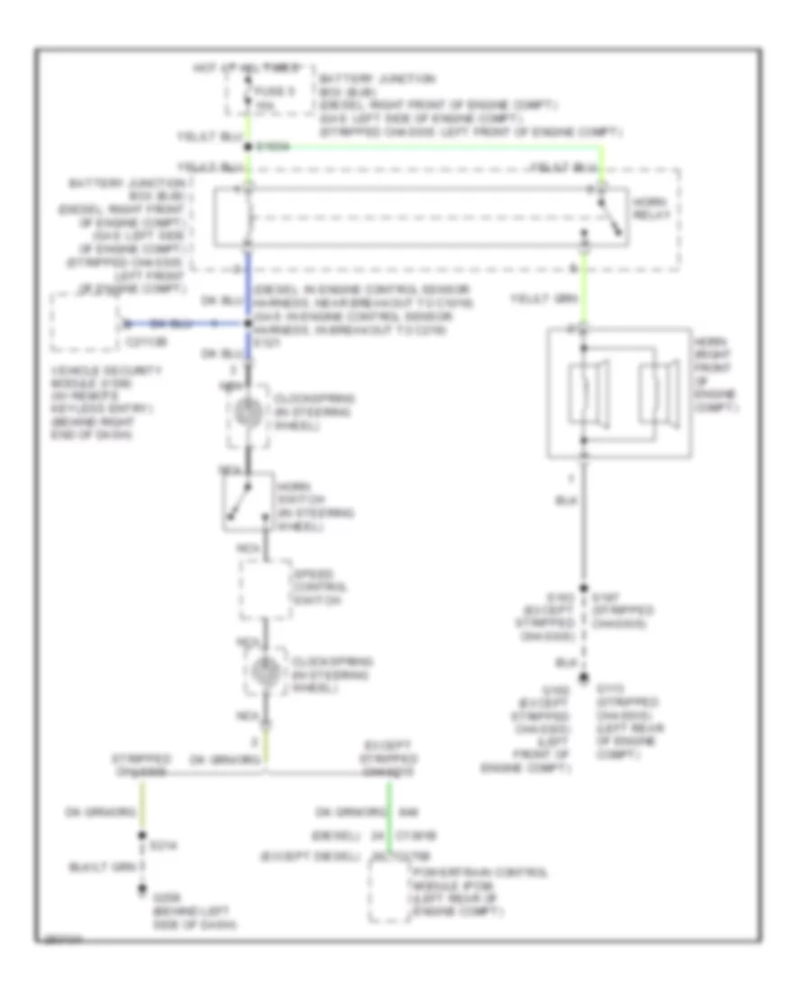
List of elements for Horn Wiring Diagram for Ford Econoline E250 2008:
- (diesel)
- (diesel: in engine control sensor harness, near breakout to c1019) (gas: in engine control sensor harness, in breakout to c219) s121
- (except diesel)
- 15a
- Battery junction box (bjb) (diesel: right front of engine compt) (gas: left side of engine compt) (stripped chassis: left front of engine compt)
- C1381b
- C175b
- C2113b
- Clockspring (in steering wheel)
- Except stripped chassis
- Fuse 5
- G102 (except stripped chassis) (left front of engine compt)
- G113 (stripped chassis) (left rear of engine compt)
- G208 (behind left side of dash)
- Horn (right front of engine compt)
- Horn relay
- Horn switch (in steering wheel)
- Hot at all times
- Nca
- Powertrain control module (pcm) (left rear of engine compt)
- S1034
- S163 (except stripped chassis)
- S197 (stripped chassis)
- S214
- Speed control switch
- Stripped chassis
- Vehicle security module (vsm) (w/ remote keyless entry) (behind right end of dash)
 Čeština
 Dansk
Dansk Deutsch
 Ελληνικά
 English
 English
 Español
 Suomi
Suomi Français
 Français
 עברית
עברית Hrvatski
 Magyar
 Italiano
 日本語
日本語 한국어
한국어 Nederlands
 Polski
 Português
 Português
 Română
 Русский
 Slovenščina
 Svenska
 Türkçe
 中文 (中国)
 Slovenčina