POWER DOOR LOCKS
Keyless Entry Wiring Diagram for Mercury Villager Nautica 1995
 https://portal-diagnostov.com/license.html
Automotive Electricians Portal FZCO
Automotive Electricians Portal FZCO
https://portal-diagnostov.com/license.html
https://portal-diagnostov.com/license.html
Automotive Electricians Portal FZCO
Automotive Electricians Portal FZCO
List of elements for Keyless Entry Wiring Diagram for Mercury Villager Nautica 1995:
- (behind top left side of i/p, taped to harness)
- (left rear corner of cargo area)
- (not used)
- (top left of cowl panel, near door grommet)
- (top right of cowl panel, near door grommet)
- 1/2
- 1/2 input
- 3/4
- 3/4 input
- 5/6
- 5/6 input
- 7/8
- 7/8 input
- 9/0
- 9/0 input
- Battery
- C219
- C221
- Chime control
- Closed
- Diode junction box
- Door ajar input
- Door ajar warning/ rear interior lamp control
- Door lock control
- Door lock/unlock input
- Door open input
- Electron bat fuse 13 10a
- G200
- G200 (top left of cowl panel, near door grommet)
- G200 (top left of cowl panel, near door grommet)
- G203
- G409/g411
- Ground
- Hot at all times
- I/p fuse/relay panel
- Ignition key reminder switch
- Illuminated entry signal input
- Illuminated entry signal output
- Illumination output
- Key in ignition input
- Key-in ign input
- Keyless entry chime (in rear of left front door)
- Keyless entry keypad assembly
- Keyless entry module (behind center of i/p, on center support brace)
- Left door jamb switch
- Left door lock actuator assembly
- Left door lock switch
- Left engine compartment fuse panel
- Liftgate latch switch
- Liftgate lock actuator
- Liftgate open input
- Lock
- Lock input
- Nca
- Open
- Pb05
- Ph01
- Ph02
- Ph03
- Ph05
- Ph06
- Ph07
- Ph08
- Ph09
- Ph11
- Ph16
- Ph18
- Ph20
- Ph31
- Ph32
- Ph34
- Ph35
- Ph38
- Ph41
- Ph42
- Phe1
- Phe2
- Pnk
- Power window fuse 30a
- Right circuit breaker (behind left side of i/p, near cowl panel)
- Right door jamb switch
- Right door lock actuator
- Right door lock switch
- Room lamp fuse 25 15a
- Sliding door ajar input
- Sliding door ajar switch
- Sliding door contact switch
- Sliding door lock actuator
- Sliding door output (delay lock)
- Timer module (behind bottom of left cowl panel)
- Unlock
- Unlock input
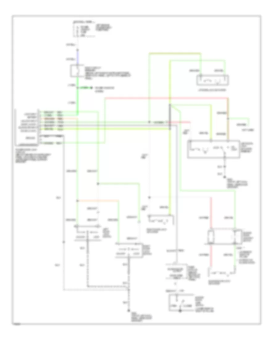
Power Door Locks Wiring Diagram for Mercury Villager Nautica 1995
List of elements for Power Door Locks Wiring Diagram for Mercury Villager Nautica 1995:
- (behind left side of instrument panel, near cowl panel, left of i/p fuse/relay
- (in front of **
- (in rear of * right "b" pillar)
- (lower rear of right "b" pillar)
- (not used)
- 30a
- Ajar switch
- Battery
- C311
- C329
- Closed
- Door lk cntl
- Door open
- G200 (top of left cowl panel, near door grommet)
- Ground
- Hot at all times
- Input
- L194
- Left door lock switch
- Left door lock actuator assembly
- Left engine compartment fuse panel
- Liftgate lock actuator
- Lock
- Lock input
- Lock/unlock in
- Open
- Output
- Panel)
- Pb01
- Pb02
- Pb04
- Pb05
- Pbo5
- Ph31
- Ph34
- Ph35
- Phe2
- Power window fuse
- Power door lock module (below center of instrument panel, mounted on center instrument panel support bracket)
- Power windows
- Red
- Right door lock switch
- Right circuit breaker
- Right door lock actuator
- Sliding door
- Sliding door
- Sliding door contact switch
- Sliding door lock actuator
- Sliding door)
- Sliding dr input
- System
- Timer module (behind bottom of left cowl panel)
- Un- lock
- Unlock
- Unlock input

 Čeština
 Dansk
Dansk Deutsch
 Ελληνικά
 English
 English
 Español
 Suomi
Suomi Français
 Français
 עברית
עברית Hrvatski
 Magyar
 Italiano
 日本語
日本語 한국어
한국어 Nederlands
 Polski
 Português
 Português
 Română
 Русский
 Slovenščina
 Svenska
 Türkçe
 中文 (中国)