SHIFT INTERLOCK
Electronic Parking Brake Wiring Diagram for Porsche Panamera Turbo 2013
 https://portal-diagnostov.com/license.html
Automotive Electricians Portal FZCO
Automotive Electricians Portal FZCO
https://portal-diagnostov.com/license.html
https://portal-diagnostov.com/license.html
Automotive Electricians Portal FZCO
Automotive Electricians Portal FZCO
List of elements for Electronic Parking Brake Wiring Diagram for Porsche Panamera Turbo 2013:
- 10a
- Can high
- Can low
- Clutch
- Clutch pedal sensor
- Clutch switch
- Computer data lines system
- Display button
- Dme control unit (right rear of engine compt)
- Epb
- Epb button
- Epb control unit (right side of luggage comp)
- Except hybrid
- Fun ind
- Function display
- Fuse 40a
- Fuse 5a
- Gpa
- Hot at all times
- Hot w/ terminal 15 relay energized
- Hybrid
- Instrument cluster
- Interior lights system
- Interlock
- Left epb motor
- Left front fuse box (left kick panel)
- Lh mtr +
- Lh mtr -
- Lh sens +
- Lh sens -
- Low start enable
- Maxi fuse box
- Mb13 (left side of support frame)
- Mb22 (top of right "c" pillar)
- Mb9 (left "a" pillar)
- Motor a
- Motor b
- Power distribution system
- Prk brk
- Rear fuse carrier b
- Red
- Rh mtr+
- Rh mtr-
- Rh sens +
- Rh sens -
- Right epb motor
- Sens r+
- Sens r-
- Sensor +
- Sensor -
- Sw out a
- Sw out b
- Sw out c
- Sw out d
- Switch 1
- Switch 3
- Switch 4
- Switch 6
- Term 15
- Term 30
- Term 31
- Term 58 d
- Terminal 30tp
- X430
- X440
- X901
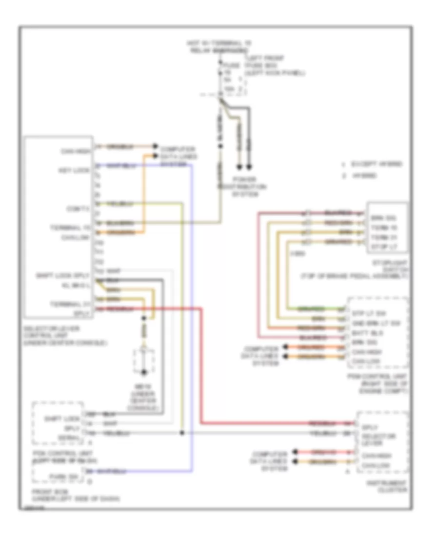
Shift Interlock Wiring Diagram for Porsche Panamera Turbo 2013
List of elements for Shift Interlock Wiring Diagram for Porsche Panamera Turbo 2013:
- 10a
- Batt bls
- Brk sig
- Can high
- Can low
- Com tx
- Computer data lines system
- Except hybrid
- Front bcm (under left side of dash)
- Fuse 5a
- Gnd brk lt sw
- Hot w/ terminal 15 relay energized
- Hybrid
- Instrument cluster
- Key lock
- Kl mag l
- Left front fuse box (left kick panel)
- Mb19 (under center console)
- Park sw
- Pdk control unit (left side of dash)
- Power distribution system
- Psm control unit (right side of engine compt)
- Selector lever
- Selector lever control unit (under center console)
- Serial
- Shift lock
- Shift lock sply
- Sply
- Stop lt
- Stoplight switch (top of brake pedal assembly)
- Stp lt sw
- Term 15
- Term 31
- Terminal 15
- Terminal 31
- X960

 Čeština
 Dansk
Dansk Deutsch
 Ελληνικά
 English
 English
 Español
 Suomi
Suomi Français
 Français
 עברית
עברית Hrvatski
 Magyar
 Italiano
 日本語
日本語 한국어
한국어 Nederlands
 Polski
 Português
 Português
 Română
 Русский
 Slovenščina
 Svenska
 Türkçe
 中文 (中国)