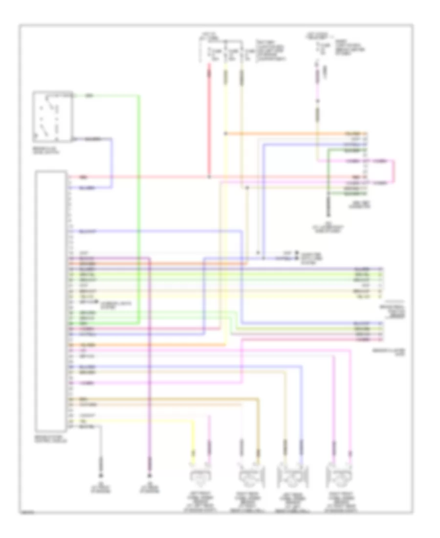
ANTI-LOCK BRAKES
Anti-lock Brakes Wiring Diagram, Except Hybrid for Mazda Tribute i Sport 2008
 https://portal-diagnostov.com/license.html
Automotive Electricians Portal FZCO
Automotive Electricians Portal FZCO
https://portal-diagnostov.com/license.html
https://portal-diagnostov.com/license.html
Automotive Electricians Portal FZCO
Automotive Electricians Portal FZCO
List of elements for Anti-lock Brakes Wiring Diagram, Except Hybrid for Mazda Tribute i Sport 2008:
- Abs control module
- Abs test connector
- Battery junction box (on left side of engine compartment)
- Brake fluid level switch
- Brake pedal position switch (on bracket, above brake pedal)
- Computer data lines system
- Fuse 15a
- Fuse 20a
- Fuse 50a
- Fuse 5a
- G11 (left front of engine compartment)
- G14 (at lower left side of dash)
- G5 (at left front of engine compt)
- Hot at all times
- Hot in run or start
- J-2280b
- J-2280d
- J-2280f
- Left front wheel speed sensor (at left rear of engine compt)
- Left rear wheel speed sensor (at left rear wheelwell)
- Microcomputer
- Red
- Right front wheel speed sensor (at right rear of engine compt)
- Right rear wheel speed sensor (at right rear wheelwell)
- Sensor cluster
- Smart junction box (behind center of dash)
- Traction assist disable switch
Anti-lock Brakes Wiring Diagram, Hybrid for Mazda Tribute i Sport 2008
List of elements for Anti-lock Brakes Wiring Diagram, Hybrid for Mazda Tribute i Sport 2008:
- Abs test connector
- Battery junction box (on left side of engine compartment)
- Brake fluid level switch
- Brake pedal position sensor
- Brake system control module
- Computer data lines system
- Fuse 50a
- Fuse 5a
- G12 (at lower right side of dash)
- G8 (at front of engine)
- G9 (at rear of engine)
- Hot at all times
- Hot in run or start
- Interior lights system
- J-2280b
- Left front wheel speed sensor (at left rear of engine compt)
- Left rear wheel speed sensor (at left rear wheelwell)
- Red
- Right front wheel speed sensor (at right rear of engine compt)
- Right rear wheel speed sensor (at right rear wheelwell)
- Sensor cluster (4wd)
- Smart junction box (behind center of dash)

 Čeština
 Dansk
Dansk Deutsch
 Ελληνικά
 English
 English
 Español
 Suomi
Suomi Français
 Français
 עברית
עברית Hrvatski
 Magyar
 Italiano
 日本語
日本語 한국어
한국어 Nederlands
 Polski
 Português
 Português
 Română
 Русский
 Slovenščina
 Svenska
 Türkçe
 中文 (中国)