
 Čeština
 Dansk
Dansk Deutsch
 Ελληνικά
 English
 English
 Español
 Suomi
Suomi Français
 Français
 עברית
עברית Hrvatski
 Magyar
 Italiano
 日本語
日本語 한국어
한국어 Nederlands
 Polski
 Português
 Português
 Română
 Русский
 Slovenščina
 Svenska
 Türkçe
 中文 (中国)

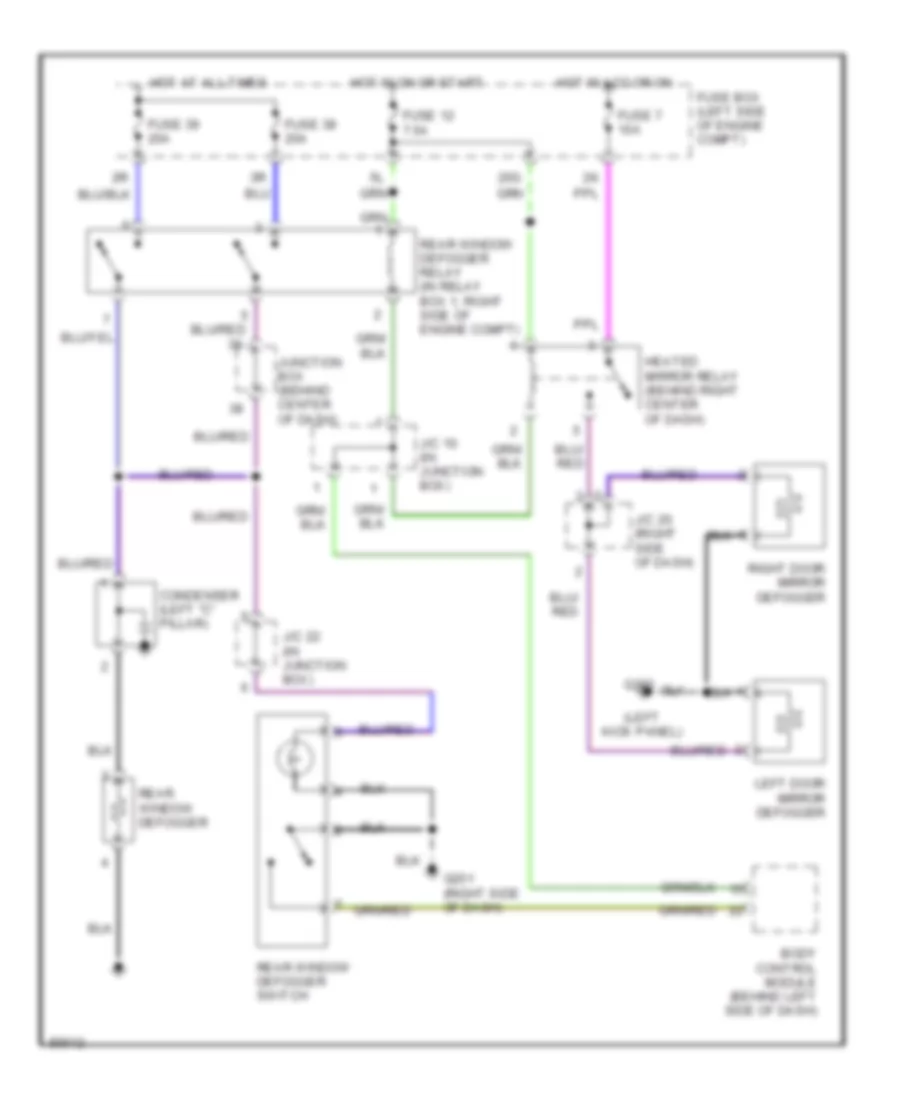
DEFOGGERS
Defogger Wiring Diagram for Nissan Maxima SE 1996
List of elements for Defogger Wiring Diagram for Nissan Maxima SE 1996:

AIR CONDITIONINGANTI-LOCK BRAKESANTI-THEFTBODY COMPUTERCOMPUTER DATA LINESCOOLING FANCRUISE CONTROLDEFOGGERSENGINE PERFORMANCEEXTERIOR LIGHTSHEADLIGHTSGROUND DISTRIBUTIONHORNINSTRUMENT CLUSTERINTERIOR LIGHTSPOWER ANTENNAPOWER DISTRIBUTIONPOWER DOOR LOCKSPOWER MIRRORSPOWER SEATSPOWER TOP/SUNROOFPOWER WINDOWSRADIOSHIFT INTERLOCKSSTARTING/CHARGINGSUPPLEMENTAL RESTRAINTSTRANSMISSIONTRUNK, TAILGATE, FUEL DOORWARNING SYSTEMSWIPER/WASHER