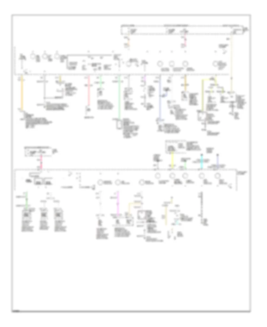
INSTRUMENT CLUSTER
Instrument Cluster Wiring Diagram for Chevrolet Camaro 1994
List of elements for Instrument Cluster Wiring Diagram for Chevrolet Camaro 1994:
- (not used)
- (top of right front shock tower)
- (v6 vin s) (v8 vin p)
- 100 f/
- Abs fail
- Abs inop indic- ator
- Air bag indicator
- Asr ind. ctrl
- Asr indicator
- Audio alarm module
- B1 sir ind. ctrl
- B2 abs fail out
- B5 low trac ind. ctrl
- Bat
- Brake combo valve (abs) (closed w/ unequal pressure)
- Brake ind. ctrl
- Brake indicator
- C12
- C13
- C15
- C16
- C2 tan
- Check gauges indic- ator
- Convenience center (mounted to i/p carrier, left of steering column)
- Coolant level latching module (center of i/p, above floor tunnel)
- Coolant temp. gauge
- Coolant temp. monitor
- Cruise control
- D12
- D15
- D16
- Diagnostic energy reserve module (behind i/p, right of glove box)
- Drl module (behind i/p, left of glove box)
- Electronic brake/traction control module (under left side of i/p, near grommet)
- Engine coolant level switch (top right side of radiator)
- Engine coolant temperature sender (v6 vin s-left front of engine, on head) (v8 vin p-mounted in left head, between cyls 1&3) (1365 @ 55 @260 f)
- Engine speed output
- Exterior lights system
- Fasten seat belt ind. ctrl
- Fasten seat belt indicator
- Fuel gauge
- Fuel gauge sender (full- empty- 1 )
- Fuse block: i/p
- G103
- G109 (top right side of radiator)
- G120 (v6 vin s-top right side of engine, on intake manifold) (v8 vin p-right side of engine, above starter)
- G200 (left kick panel)
- G300 (under driver's seat)
- Gauges fuse 9 10a
- Generator
- Generator sense
- Gnd
- Headlights system
- Hi beam indicator
- Hot at all times
- Hot in accy or run
- Hot in run, bulb test or start
- Hydraulic modulator assembly (left front of engine compt)
- Ign
- Ignition control module (left front of engine)
- Illumination (6 bulbs)
- Indicator contols
- Instrument cluster
- Interior lights system (rheostat)
- L gen out
- Left turn indicator
- Low coolant ind. ctrl
- Low coolant indicator (v8 vin p only)
- Low oil indic- ator
- Low oil input
- Low trac indicator
- Malfunction indicator
- Mil ind. ctrl
- Nca
- Odometer
- Oil level sensor (lower left side of engine, in oil pan) (open w/ low oil level)
- Oil press. gauge
- Oil press. monitor
- Oil pressure sender (v6 vin s-lower left side of engine, above oil filter) (v8 vin p-mounted to top center of engine, rear of manifold) (@90 -high) (@10 -low)
- Park brake switch
- Pcm bat fuse 4 10a
- Pnk
- Pnk d13
- Pnk d7
- Powertrain control module (rearward of right front shock tower)
- Rap module (center of i/p, above floor tunnel)
- Red
- Right turn indicator
- Security ind. ctrl
- Security indicator
- Skip shift ind. ctrl
- Skip shift indicator
- Solid state
- Speed- ometer
- Tachometer
- Tan
- Theft deterrent module (behind i/p, right of radio)
- V6 vin s
- V8 vin p
- Vehicle speed output
- Voltmeter
- W/ au3
- W/drl
- W/o au3
- W/o drl
- Windows c.b. 30a
 Čeština
 Dansk
Dansk Deutsch
 Ελληνικά
 English
 English
 Español
 Suomi
Suomi Français
 Français
 עברית
עברית Hrvatski
 Magyar
 Italiano
 日本語
日本語 한국어
한국어 Nederlands
 Polski
 Português
 Português
 Română
 Русский
 Slovenščina
 Svenska
 Türkçe
 中文 (中国)
 Slovenčina