WARNING SYSTEMS
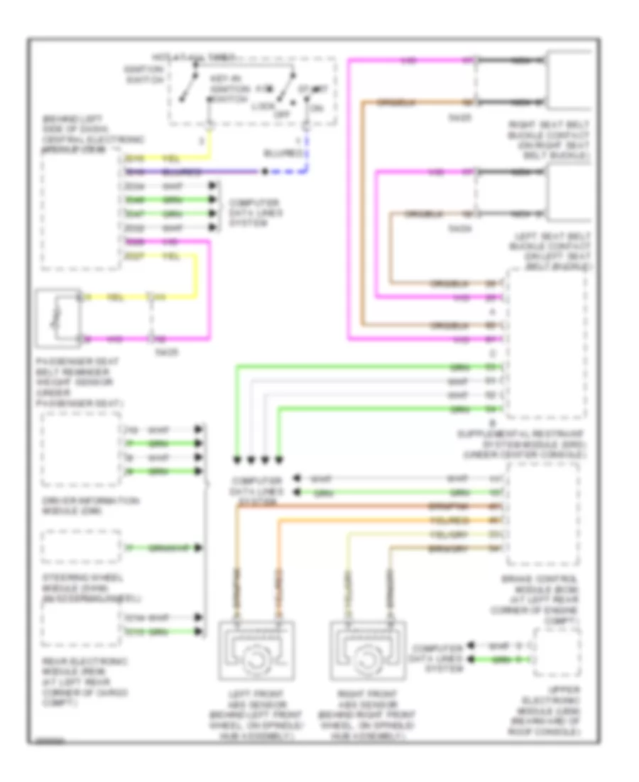
Warning Systems Wiring Diagram for Volvo XC90 2011
List of elements for Warning Systems Wiring Diagram for Volvo XC90 2011:
- (behind left side of dash) central electronic module (cem)
- 54/24
- 54/25
- Acc
- Brake control module (bcm) (at left rear corner of engine compt)
- C13
- C14
- Computer data lines system
- D15
- D16
- D27
- D28
- D32
- D34
- D47
- D49
- Driver information module (dim)
- Hot at all times
- Ignition switch
- Key-in ignition switch
- Left front abs sensor (behind left front wheel, on spindle/ hub assembly)
- Left seat belt buckle contact (on left seat belt buckle)
- Lock
- Nca
- Off
- Passenger seat belt reminder weight sensor (under passenger seat)
- Rear electronic module (rem) (at left rear corner of cargo compt)
- Right front abs sensor (behind right front wheel, on spindle/ hub assembly)
- Right seat belt buckle contact (on right seat belt buckle)
- Start
- Steering wheel module (swm) (in steering wheel)
- Upper electronic module (uem) (rearward of roof console)
 Čeština
 Dansk
Dansk Deutsch
 Ελληνικά
 English
 English
 Español
 Suomi
Suomi Français
 Français
 עברית
עברית Hrvatski
 Magyar
 Italiano
 日本語
日本語 한국어
한국어 Nederlands
 Polski
 Português
 Português
 Română
 Русский
 Slovenščina
 Svenska
 Türkçe
 中文 (中国)
 Slovenčina