POWER DISTRIBUTION
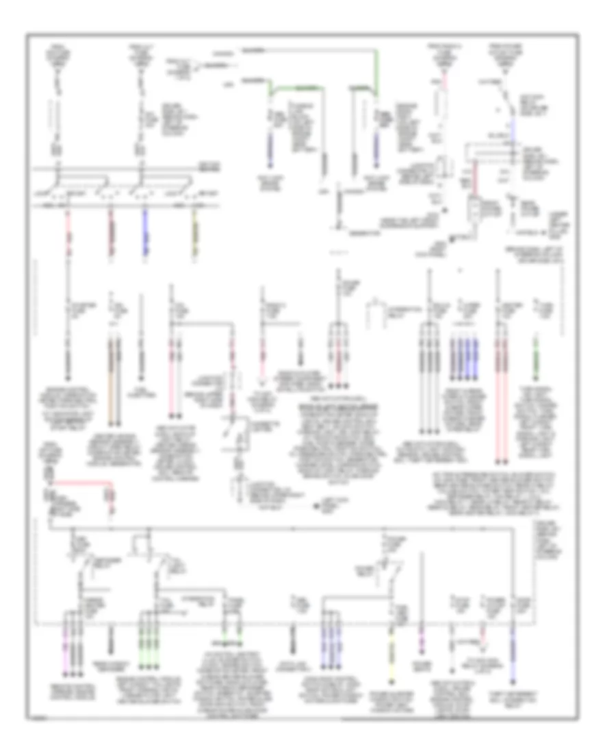
Power Distribution Wiring Diagram (1 of 2) for Toyota Sienna CE 1999
 https://portal-diagnostov.com/license.html
Automotive Electricians Portal FZCO
Automotive Electricians Portal FZCO
https://portal-diagnostov.com/license.html
https://portal-diagnostov.com/license.html
Automotive Electricians Portal FZCO
Automotive Electricians Portal FZCO
List of elements for Power Distribution Wiring Diagram (1 of 2) for Toyota Sienna CE 1999:
- (canada)
- (diagram 2 of 2)
- (on left side of engine compt)
- (on left side of engine compt) engine room r/b 1
- (u.s.)
- A b
- A w/o tow package w/ tow package b
- A/c amplifier, a/c switch
- A/c condenser fan motor, radiator fan motor, fan 2 relay, fan 3 relay
- A/c fuse 5a
- A/f heater relay, air fuel ratio sensors
- A/f htr fuse 25a
- Alt fuse 140a
- Alt-s fuse 5a
- Am2 fuse 30a
- Battery
- Blower motor
- C10
- California
- Cds fuse 30a 40a
- Center air bag sensor assembly, combination meter, slide door ecu data link connector 1
- Combination meter, clock, door courtesy switches, courtesy diodes, dome diodes, drl main relay, automatic light sensor, interior light, courtesy switches, vanity lights, interior & courtesy lights,
- Combination meter, hazard switch, front turn signal lights, rear combination lights, turn signal flasher turn signal indicator lights
- Combination switch, drl 2 diode, integration relay, drl 4 relay (coil)
- Compartment light & light switch, personal light
- Data link connector 1, engine control module, fuel pump & sender, vsv, heated oxygen sensors, idle air control valve, mass airflow meter, st relay
- Dim relay
- Dome fuse 10a
- Driver side r/b 5 (behind left side of dash)
- Drl fuse 5a
- Ecu-b fuse 10a
- Efi fuse 15a
- Efi relay
- Engine control module
- Engine room j/b 2
- Engine room j/b 2 (on left side of engine compt)
- Engine room r/b 2 (on left side of engine compt near battery)
- Fan 1 relay
- From c radio 1 fuse (diagram 1 of 2)
- Fusible link block (on left side of engine compt)
- Generator
- Hazard fuse 10a
- Head relay
- Heater relay
- High beam indicator indicator light, combination switch, headlights, drl drl relay 4
- Horn fuse 10a
- Horn relay
- Horn switch
- Horns
- Htr fuse 50a
- Inp fuse 100a
- Integration relay, theft deterrent ecu, wireless door lock ecu, luggage
- J12
- Junction connector j1
- K10
- K11
- Left head fuse 15a
- Left head lower fuse 10a
- Left low beam head- light
- Main fuse 40a
- Main relay 1
- Main relay 2
- Passenger side r/b 4 (at right kick panel)
- Radiator fan motor
- Radio & player, stereo component amplifier
- Radio 1 fuse 20a
- Rdi fuse 10a 40a
- Rear blower motors, rear blower resistors, front heater blower switch, rear heater blower switch, rear hi relay, rear lo relay, rear m1 relay, rear m2 relay, rear heater relay
- Red
- Right head fuse 15a
- Right head lower fuse 10a
- Right low beam head- light
- Rr a/c fuse 40a
- Short pin
- Theft horn, theft deterrent ecu
- To am1 fuse (diagram 2 of 2)
- To generator or abs fuse
- To hazard fuse (diagram 1 of 2)
- To i4 splice
- To ignition switch (diagram 2 of 2)
Power Distribution Wiring Diagram (2 of 2) for Toyota Sienna CE 1999
List of elements for Power Distribution Wiring Diagram (2 of 2) for Toyota Sienna CE 1999:
- (behind dash, left of steering column) driver side j/b 1
- (left kick panel) g200
- (under left center pillar) g308
- A/c switch, ashtray illum, blower switch, clock, hazard switch, combination meter, front & rear heater blower switches, radio & player, rear window defogger switch, rheostat, quarter window switch, power slide door main switch, front & rear power slide door control switches
- A/c triple pressure switch, blower switch, a/c amplifier, front heater blower switch, rear heater blower switch, rear hi relay, volume switch, water temp switch 1 & 2, defogger relay, fan relay 1, 2 & 3, main relay 1, rear lo relay, rear m1 relay, rear m2 relay, rear relay, front heater relay, rear heater relay, main relay 2
- A/t indicator light switch & back-up light switch, start relay
- Abs abs fuse fuse 60a 60a
- Abs actuator & & ecu, cruise control ecu, engine control module, stop- lights, stop- light switch
- Abs actuator & ecu,
- Abs actuator & ecu, automatic light control sensor, cruise control ecu, theft deterrent ecu
- Abs actuator & ecu, back-up light relay, center airbag sensor assembly, combination meter, clock, cruise control ecu, remote control mirrors
- Abs fuse 60a
- Acc
- Acc main relay (on driver side j/b 1)
- Am1 fuse 40a
- Anti-lock brake system
- Back-up light switch, brake fluid level warning switch, combination meter, back-up lights, cruise control ecu seat belt, od main switch, warning light, drl main relay, a/t indicator switch, ecm fuel pump & sender, diode (park/neutral position switch), oil pressure switch, park/neutral position switch, generator, washer level warning switch, back-up light relay, parking brake switch, slide door switch
- Canada
- Center air bag sensor assembly, circuit open relay, combination meter, engine control module, generator,
- Cig fuse 15a
- Cigarette lighter
- D pnk
- Data link connector 3
- Def fuse 30a
- Defogger relay
- Door fuse 20a
- Driver side j/b 1 (behind dash, left of steering column)
- Ecu-ig fuse 15a
- Engine control module, combination meter, park/neutral position switch,
- Engine control module, left & right taillights, front parking lights, license plate light, heater blower switch
- Engine room r/b 3 (on left side of engine compt, near battery)
- From alt fuse (diagram 1 of 2)
- From alt fuse a (diagram 1 of 2)
- From am2 fuse (diagram 1 of 2)
- From inp fuse (diagram 1 of 2)
- From power outlet fuse (diagram 2 of 2)
- From radio 2 fuse (diagram 2 of 2)
- Front & rear wiper & washer switch, front & rear wiper motors, front & rear washer motors, rear wiper relay
- Front power outlet
- Fuel injectors
- Fusible link block (on left side of engine compt, near battery)
- G104 (near the left front suspension support)
- G12
- G13
- G203 (right kick panel)
- Gauge fuse 10a
- Generator
- H10
- Heater fuse 10a
- Ign fuse 5a
- Ignition switch
- Integration relay
- J10
- J11
- Junction connector j15 (behind upper right side of dash)
- Junction connector j15 (behind upper right side of dash)
- Junction connector j3 (behind left side of dash)
- Lock
- Mirror heater fuse 10a
- Moon roof control switch & relay, moon roof motor & limit switch, power window motors & switches
- Obd fuse 7.5a
- Panel fuse 7.5a
- Pnk
- Power fuse 30a
- Power quarter window switch, power vent window motors
- Power relay
- Power seats
- Power- outlet fuse 15a
- Pwr- vent fuse 15a
- Radio & player, stereo component amplifier, radio satellite switch
- Radio 2 fuse 7.5a
- Rear power outlet
- Rear window defogger
- Red
- Remote control mirrors, engine control module,
- Right side of side) b4
- S13
- Start
- Starter fuse 5a
- Stop fuse 15a
- Tail fuse 10a
- Tail light relay
- Theft deterrent ecu, integration relay
- To acc main relay (diagram 2 of 2)
- Turn fuse 7.5a
- Turn signal ind light, turn signal switch, hazard switch, turn signal flasher, left & right front turn signal light & parking light, left & right rear turn signal light
- Usa
- Wiper fuse 20a

 Čeština
 Dansk
Dansk Deutsch
 Ελληνικά
 English
 English
 Español
 Suomi
Suomi Français
 Français
 עברית
עברית Hrvatski
 Magyar
 Italiano
 日本語
日本語 한국어
한국어 Nederlands
 Polski
 Português
 Português
 Română
 Русский
 Slovenščina
 Svenska
 Türkçe
 中文 (中国)