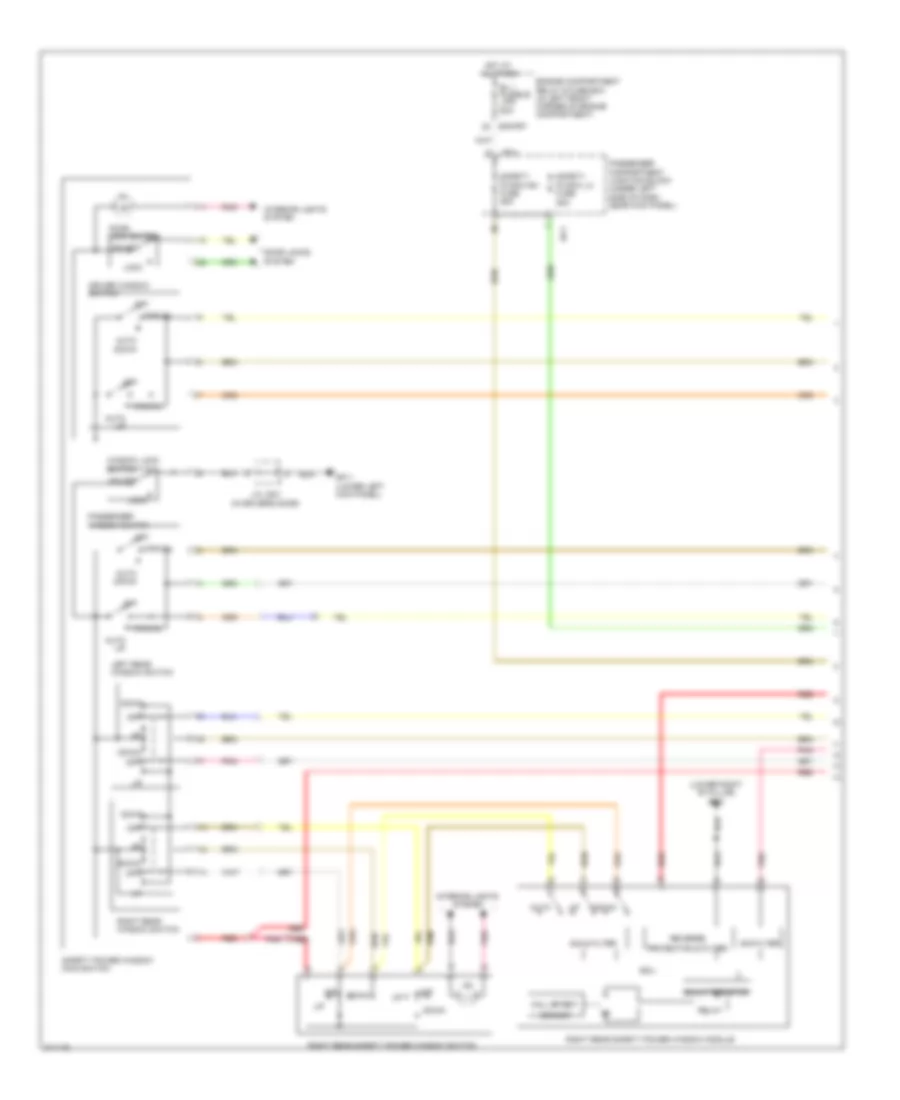
AIR CONDITIONING
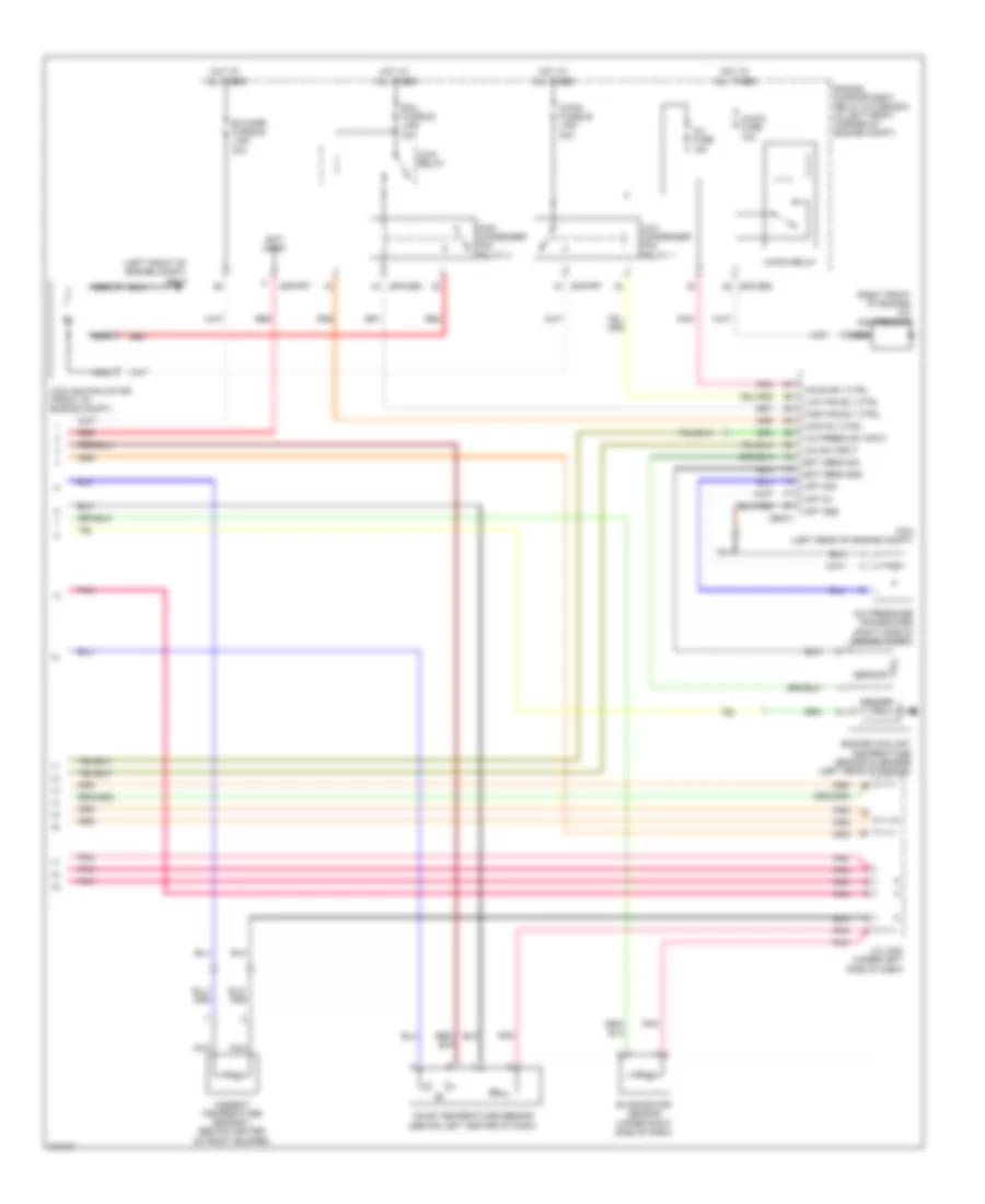
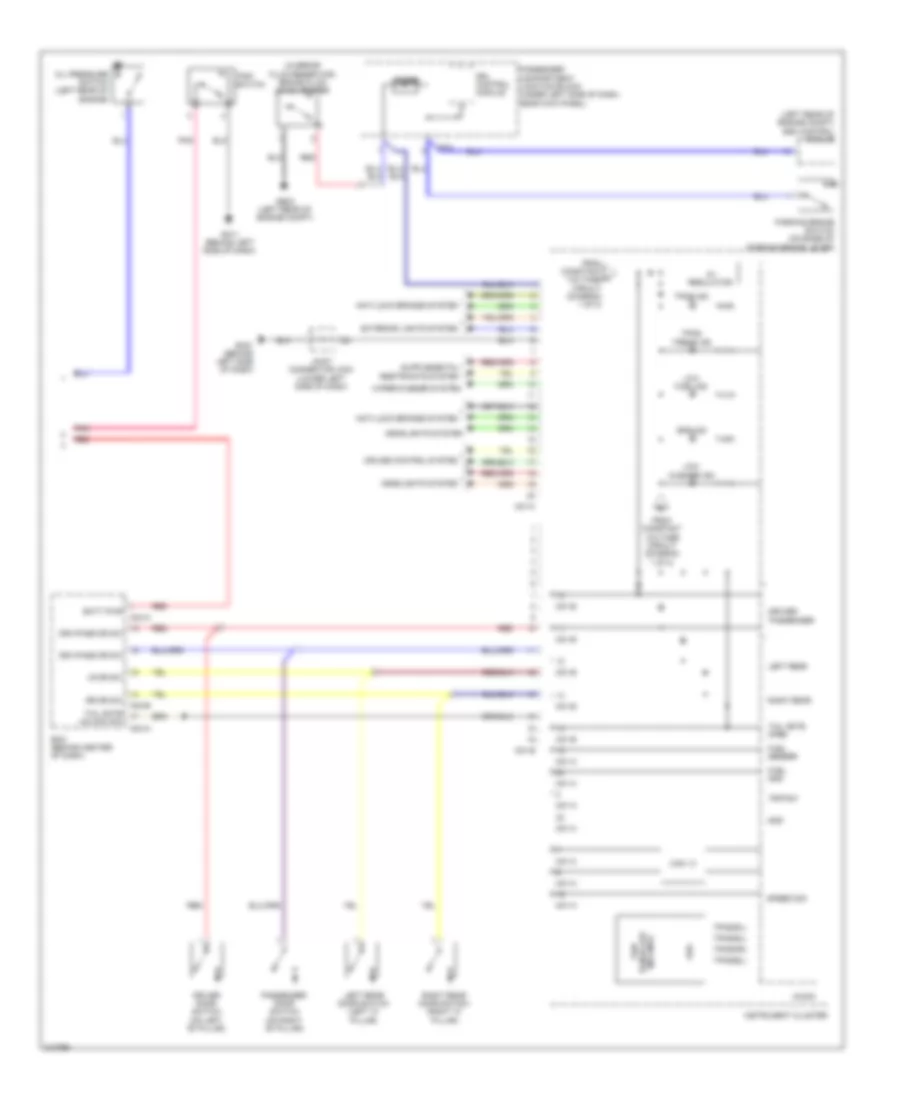
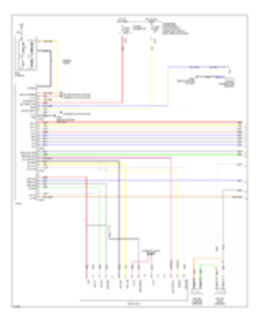
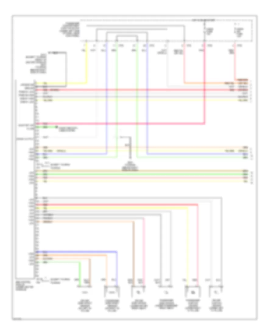
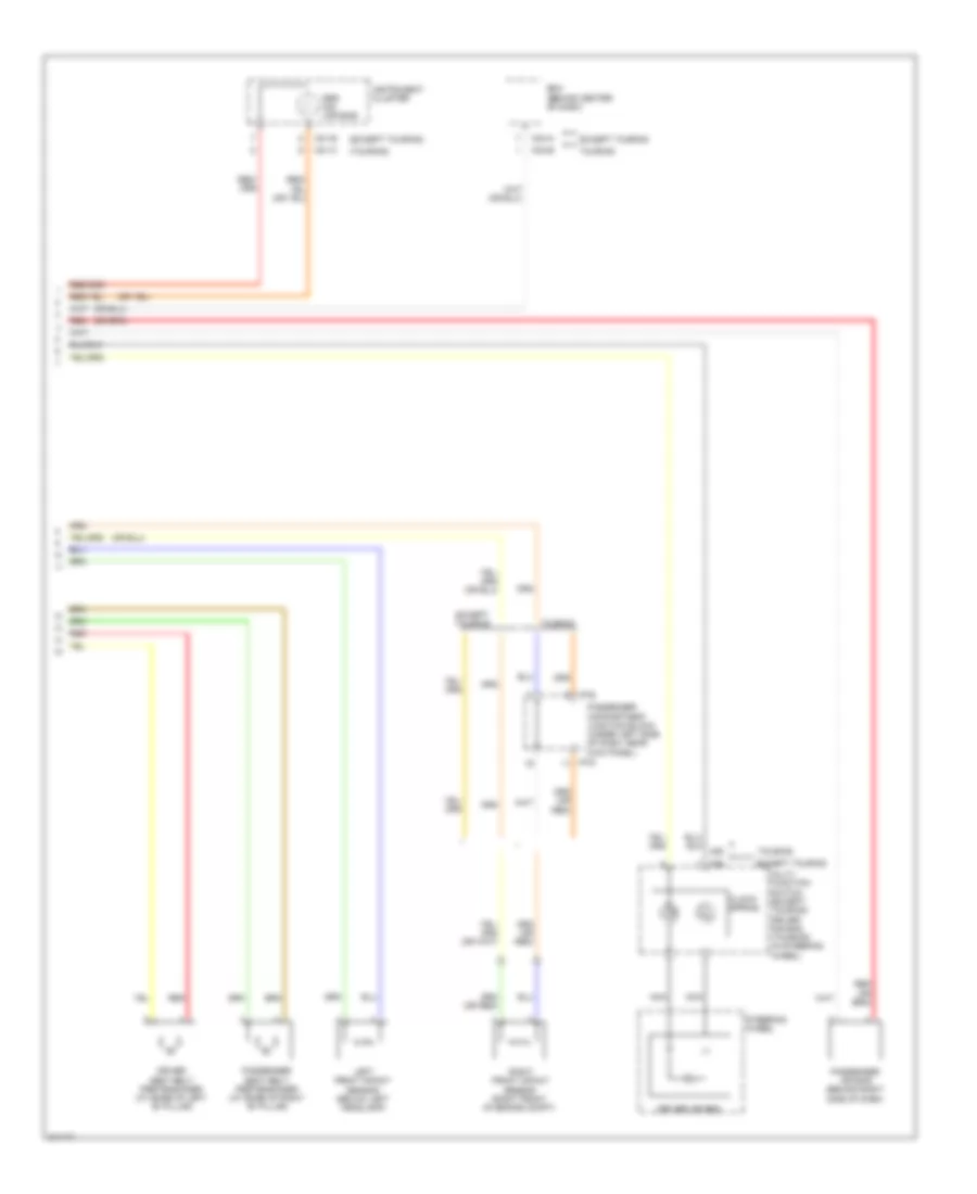
Automatic A/C Wiring Diagram (1 of 2) for Hyundai Elantra Touring SE 2010
 https://portal-diagnostov.com/license.html
Automotive Electricians Portal FZCO
Automotive Electricians Portal FZCO
https://portal-diagnostov.com/license.html
https://portal-diagnostov.com/license.html
Automotive Electricians Portal FZCO
Automotive Electricians Portal FZCO
List of elements for Automatic A/C Wiring Diagram (1 of 2) for Hyundai Elantra Touring SE 2010:
- (beside blower motor, below right side of dash) blower relay
- A/c control module (below center of dash)
- A/c output (high)
- A/c select sig (high)
- A/con fuse 10a
- A/con sw fuse 10a
- Ambient sensor (+)
- Battery power
- Blower motor (+)
- Blower motor (under right side of dash)
- Computer data lines system
- Cruise control system
- Defogger system
- Evap sens (+)
- Fet (drain)
- Fet (field effect transistor)
- Fet (gate)
- Gm31
- Ground
- Hot at all times
- Hot in on
- I/p-a
- I/p-b
- I/p-c
- I/p-g
- Ill (+)
- Ill (-)
- Incar motor (-)
- Incar sens (+)
- Intake actuator (behind upper right side of dash)
- Intake actuator f/b
- Intake actuator fre
- Intake actuator rec
- Interior lights system
- J/c jm02 (lower left side of dash)
- J/c jm03 (under left side of dash)
- K-line
- M05-a
- M05-b
- Mode actuator (behind left center of dash)
- Mode actuator def
- Mode actuator f/b
- Mode actuator vent
- Nca
- On input
- Passenger compartment junction block (under left side of dash, near kick panel)
- Photo sens (-)
- Photo sensor
- Photo sensor (top center of dash)
- Pnk
- Power connector
- Rear defogger switch
- Rear defogger switch ind
- Red
- Room lp fuse 15a
- Sens pwr (+5v)
- Sensor ground
- Temp actuator cool
- Temp actuator f/b
- Temp actuator warm
- Temperature actuator (upper right side of dash)
- Vehicle speed signal
- Wts (+)
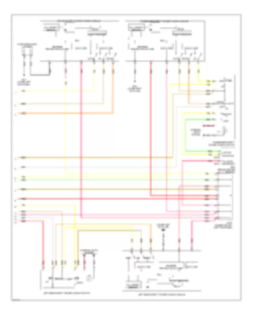
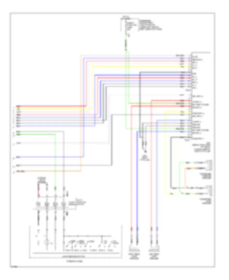
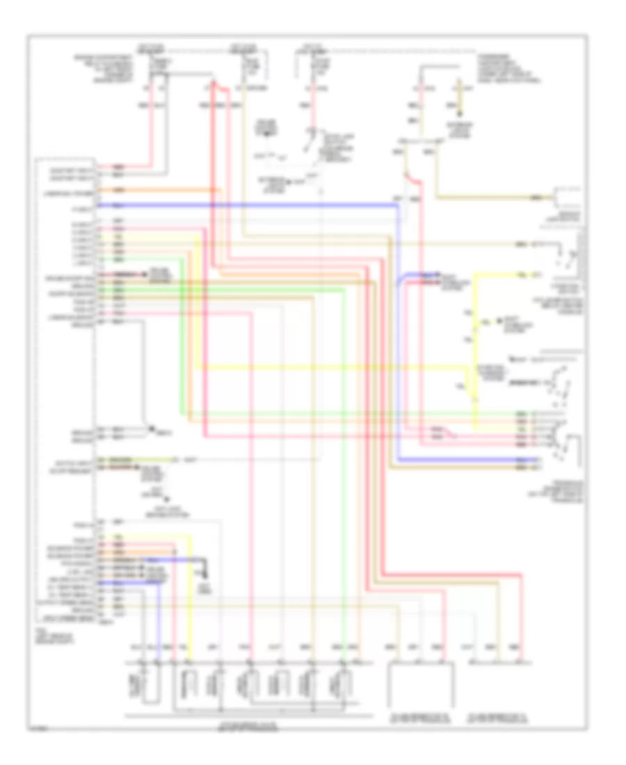
Automatic A/C Wiring Diagram (2 of 2) for Hyundai Elantra Touring SE 2010
List of elements for Automatic A/C Wiring Diagram (2 of 2) for Hyundai Elantra Touring SE 2010:
- (left front of engine compt) ge12
- (not used)
- (right front of engine) a/c compressor
- A/c press sw input
- A/c pressure transducer (right side of engine compt)
- A/c sw input
- A/con fuse 10a
- A/con relay
- A/con rly ctrl
- Ambient temperature sensor 1 (behind center of front bumper)
- Apt 5v
- Apt gnd
- Apt sig
- Blower fusible link 40a
- C/fan fusible link 40a
- Cbg-k
- Cooling fan motor (front of engine compt)
- E/r-cbg
- E/r-frt
- Ect sens gnd
- Ect sens sig
- Ecu fusible link 30a
- Engine compartment relay & fuse box (in left front corner of engine compt)
- Engine coolant temperature sensor & sender (left rear of engine)
- Evaporator sensor (upper right side of dash)
- High condenser fan relay 2
- High fan rly ctrl
- Hot at all times
- Incar temperature sensor (behind left center of dash)
- Inj fuse 15a
- J/c jm03 (under left side of dash)
- Low condenser fan relay 1
- Low fan rly ctrl
- Main relay
- Main rly ctrl
- Nca
- Pcm (left rear of engine compt)
- Pnk
- Red
- Sender
- Sensor
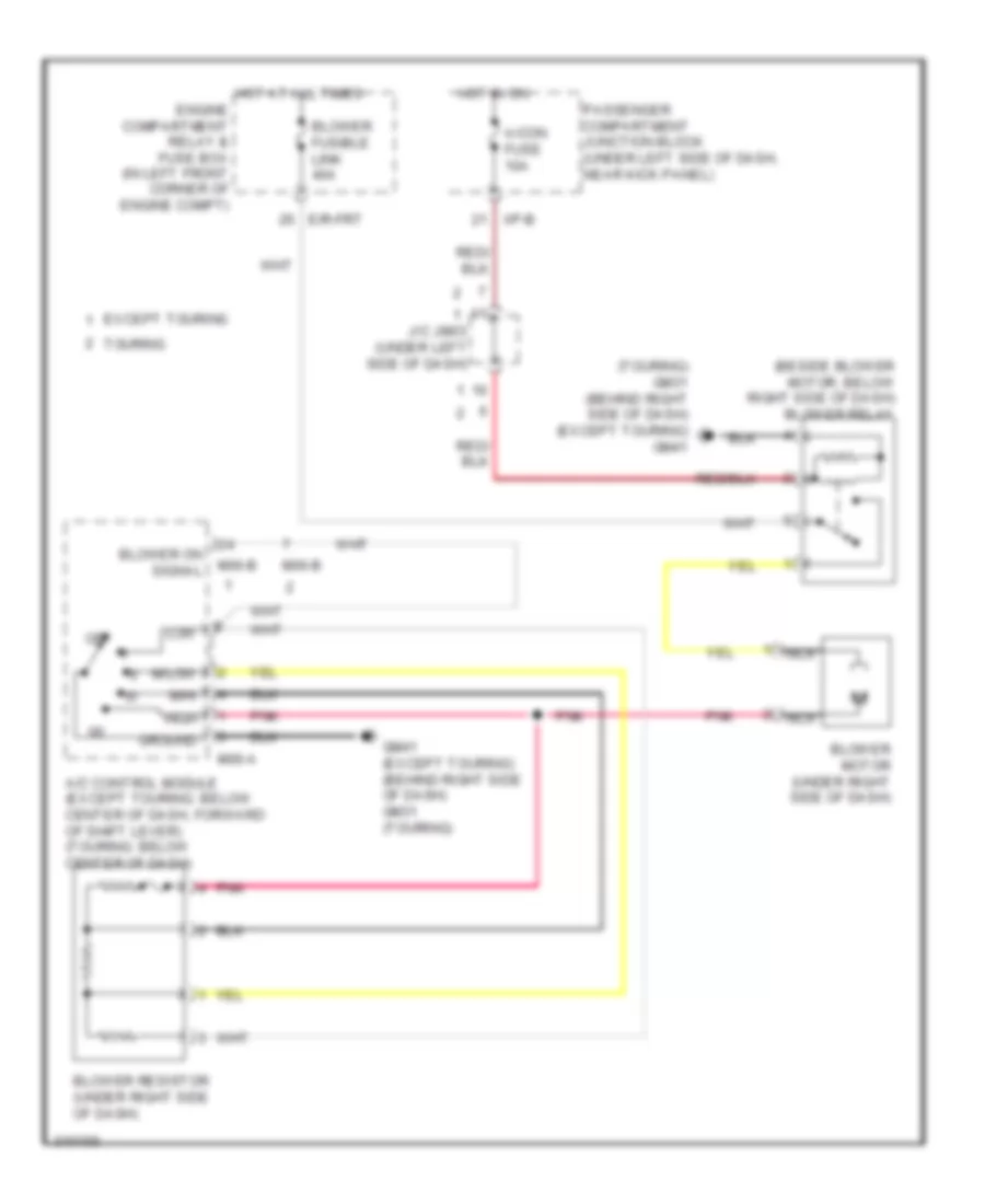
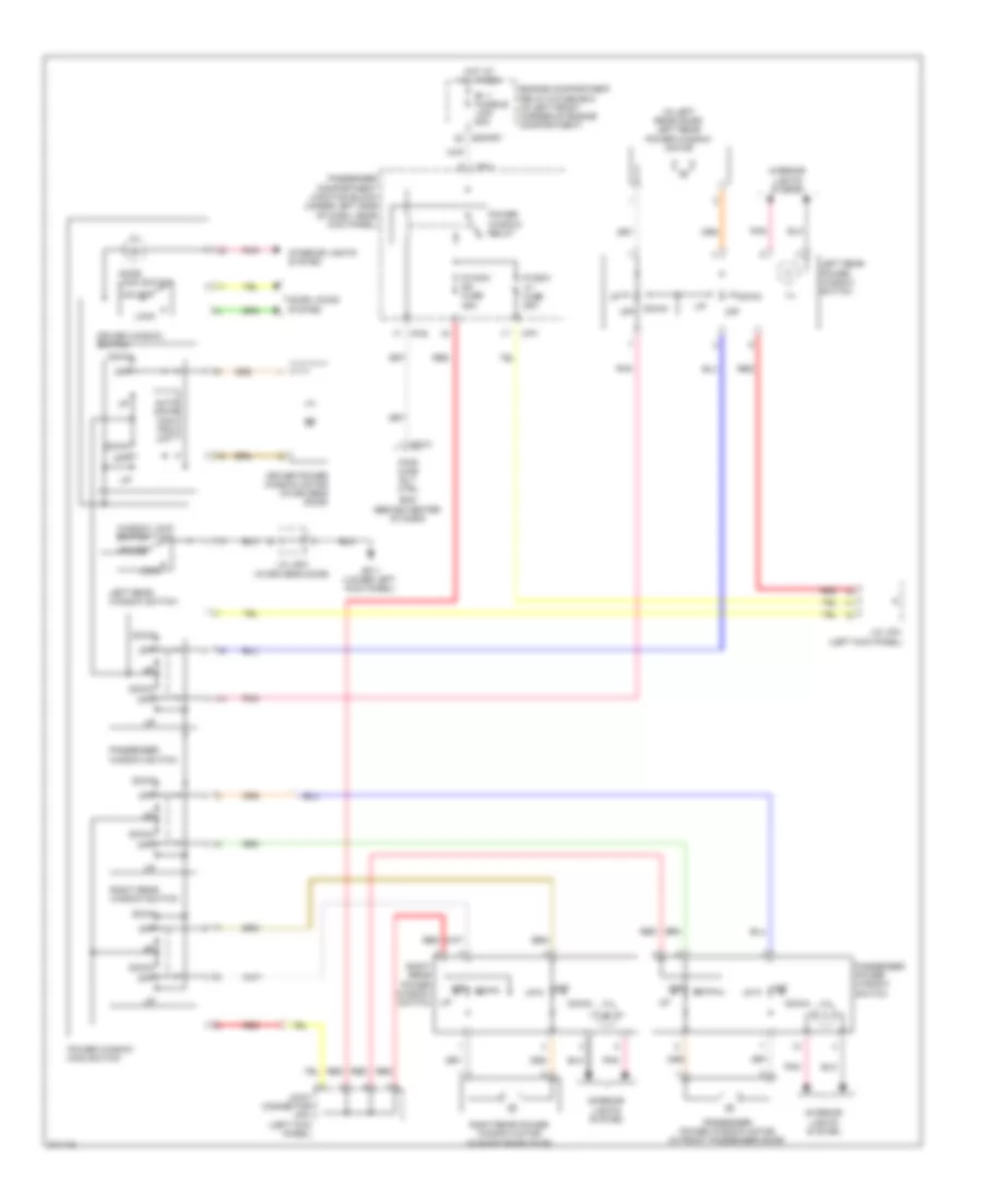
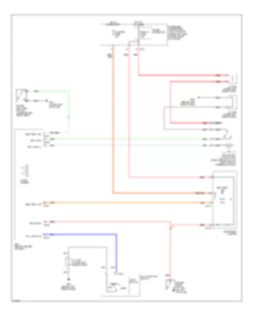
Heater Wiring Diagram for Hyundai Elantra Touring SE 2010
List of elements for Heater Wiring Diagram for Hyundai Elantra Touring SE 2010:
- (beside blower motor, below right side of dash) blower relay
- (touring) gm31 (behind right side of dash) (except touring) gm41
- A/c control module (except touring: below center of dash, forward of shift lever) (touring: below center of dash)
- A/con fuse 10a
- Blower fusible link 40a
- Blower motor (under right side of dash)
- Blower on signal
- Blower resistor (under right side of dash)
- E/r-frt
- Engine compartment relay & fuse box (in left front corner of engine compt)
- Except touring
- Gm41 (except touring) (behind right side of dash) gm31 (touring)
- Ground
- High
- Hot at all times
- Hot in on
- I/p-b
- Iii
- Iiii
- J/c jm03 (under left side of dash)
- Low
- M/hi
- M/low
- M06-a
- M06-b
- Nca
- Off
- Passenger compartment junction block (under left side of dash, near kick panel)
- Pnk
- Touring
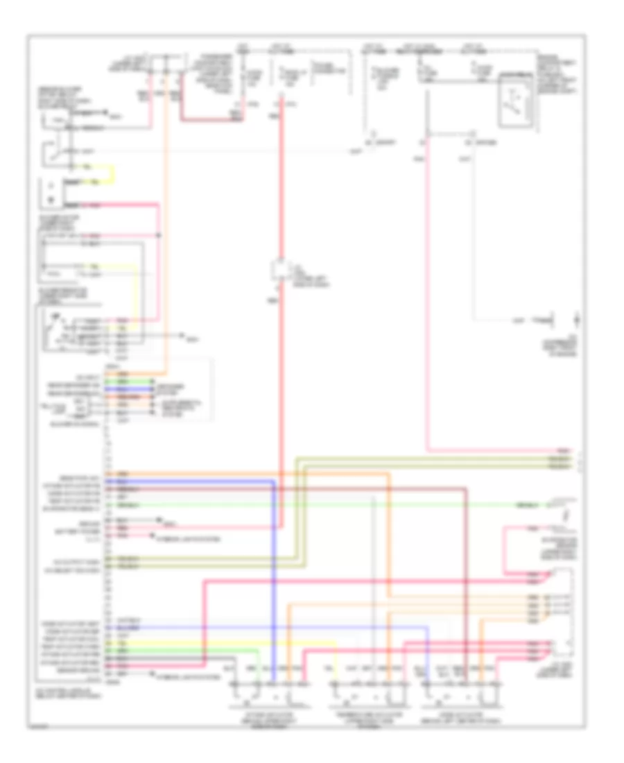
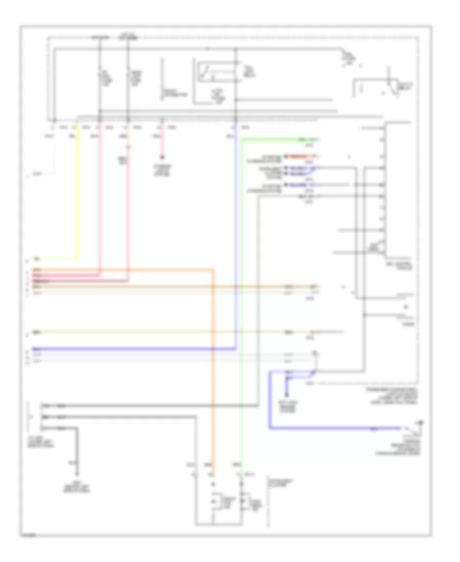
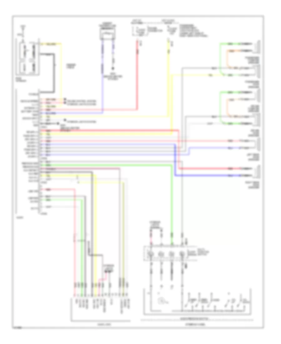
Manual A/C Wiring Diagram (1 of 2) for Hyundai Elantra Touring SE 2010
List of elements for Manual A/C Wiring Diagram (1 of 2) for Hyundai Elantra Touring SE 2010:
- (beside blower motor, below right side of dash) blower relay
- (in left front corner of engine compt)
- A/c compressor (right front of engine)
- A/c control module (below center of dash)
- A/c output (high)
- A/c select sig (high)
- A/con fuse 10a
- Battery power
- Blower fusible link 40a
- Blower motor (under right side of dash)
- Blower on signal
- Blower resistor (under right side of dash)
- Defogger system
- E/r-cbg
- E/r-frt
- Engine compartment relay & fuse box a/con relay
- Evaporator sens (+)
- Evaporator sensor (upper right side of dash)
- Gm31
- Gnd
- Ground
- High
- Hot at all times
- Hot in on
- Hot w/ main relay energized
- I/p-b
- I/p-c
- Ign1
- Iii
- Iiii
- Ill (+)
- Ill (-)
- Inj fuse 15a
- Intake actuator (behind upper right side of dash)
- Intake actuator f/b
- Intake actuator fre
- Intake actuator rec
- Interior lights system
- J/c jm02 (lower left side of dash)
- J/c jm03 (under left side of dash)
- Low
- M/hi
- M/low
- M06-a
- M06-b
- Mode actuator (behind left center of dash)
- Mode actuator def
- Mode actuator f/b
- Mode actuator vent
- Nca
- Off
- On input
- Passenger compartment junction block (under left side of dash, near kick panel)
- Pnk
- Power connector
- Rear defogger ind
- Rear defogger sw
- Red
- Room lp fuse 15a
- Sens pwr (+5v)
- Sensor ground
- Sig
- Telltale lamp
- Temp actuator cool
- Temp actuator f/b
- Temp actuator warm
- Temperature actuator (upper right side of dash)
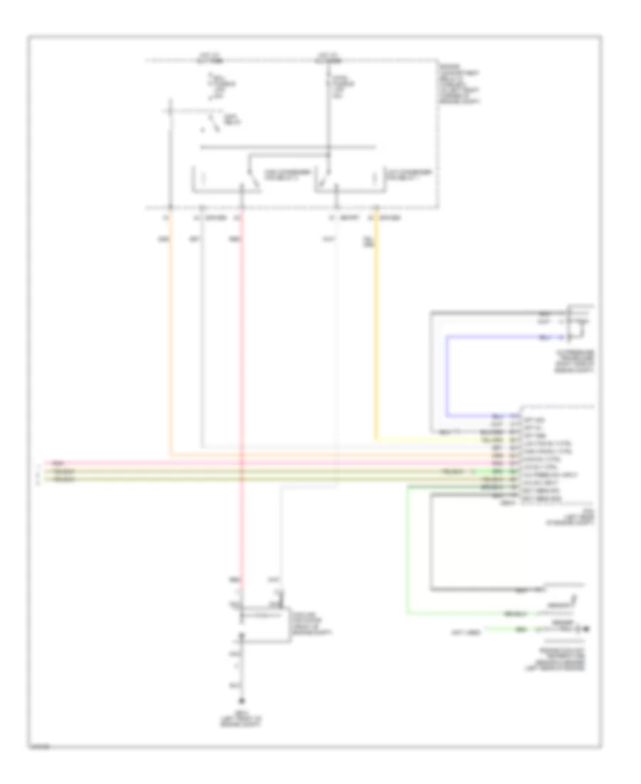
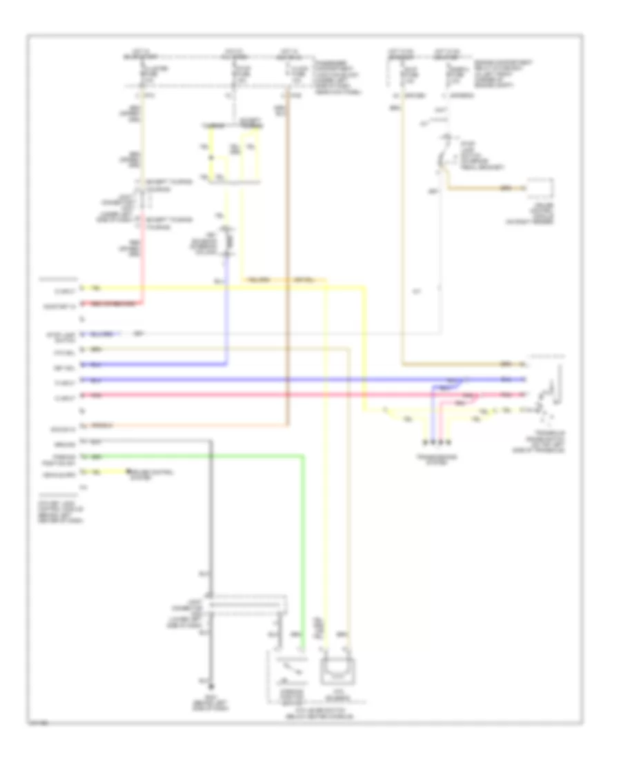
Manual A/C Wiring Diagram (2 of 2) for Hyundai Elantra Touring SE 2010
List of elements for Manual A/C Wiring Diagram (2 of 2) for Hyundai Elantra Touring SE 2010:
- (not used)
- A/c press sw input
- A/c pressure transducer (right side of engine compt)
- A/c rly ctrl
- A/c sw input
- Apt 5v
- Apt gnd
- Apt sig
- C/fan fusible link 40a
- Cbg-k
- Cooling fan motor (front of engine compt)
- E/r-cbg
- E/r-frt
- Ect sens gnd
- Ect sens sig
- Ecu fusible link 30a
- Engine compartment relay & fuse box (in left front corner of engine compt)
- Engine coolant temperature sensor & sender (left rear of engine)
- Ge12 (left front of engine compt)
- High condenser fan relay 2
- High fan rly ctrl
- Hot at all times
- Low condenser fan relay 1
- Low fan rly ctrl
- Main relay
- Main rly ctrl
- Nca
- Pcm (left rear of engine compt)
- Pnk
- Red
- Sender
- Sensor
ANTI-LOCK BRAKES
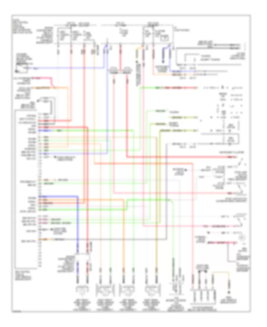
Anti-lock Brakes Wiring Diagram, with ESP for Hyundai Elantra Touring SE 2010
List of elements for Anti-lock Brakes Wiring Diagram, with ESP for Hyundai Elantra Touring SE 2010:
- (behind left side of dash) gm21
- (on base of parking brake lever) parking brake switch
- (or pnk)
- (or red)
- +ecu
- A/t & w/o auto cruise
- Abs 1 fusible link 40a
- Abs 2 fusible link 20a
- Abs fuse 10a
- Abs ind
- Abs ind ctrl
- Brake ind
- Can high
- Can low
- Cbg-a
- Cbg-k
- Check connector
- Cluster fuse 10a
- Computer data lines system
- Connector (dlc) (below left side of dash)
- Data link
- Diagnosis
- Diode
- E/r-erom
- E/r-frt
- Ebd ind ctrl
- Electronic power steering system
- Engine compartment relay & fuse box
- Engine compartment relay & fuse box (in left front corner of engine compt)
- Engine compt)
- Esc control module (left rear of engine compt)
- Esc ind ctrl
- Esc off ind
- Esc on ind
- Esc switch
- Except touring
- Exterior lights system
- Ge21 (behind left end of dash)
- Ge22 (left rear of engine compt)
- Gnd
- Ground
- Hot at all times
- Hot in on or start
- I/p junction box
- I/p-b
- I/p-c
- Ign fuse 15a
- Ill
- Instrument cluster
- Instrument cluster system
- Interior lights system
- J/c jm04 (lower left side of dash)
- Left front wheel sensor (left front wheel hub assembly)
- Left rear wheel sensor (left rear wheel hub assembly)
- Lmp sw stop
- M/t & w/o auto cruise
- M01-a
- M01-b
- M01-c
- Mtr gnd
- Multipurpose
- Nca
- Note: esc control module contains: esc solenoids, esc pump motor
- On/start
- Park brk sw
- Pnk
- Power
- Red
- Right front wheel sensor (right front wheel hub assembly)
- Right rear wheel sensor (right rear wheel hub assembly)
- Signal
- Spd sens out
- Stop fuse 15a
- Stop lamp sw
- Stop lamp switch (on brake pedal bracket)
- Tcm (except touring) pcm (touring) (left rear of engine compt)
- Touring
- Valve block d0
- Vbatt mtr rly
- Veh spd
- W/ touring & windshield defogger
- W/o windshield defogger
- Yaw rate sensor (below center console)
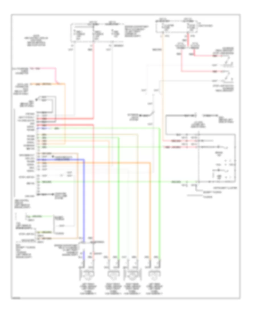
Anti-lock Brakes Wiring Diagram, without ESP for Hyundai Elantra Touring SE 2010
List of elements for Anti-lock Brakes Wiring Diagram, without ESP for Hyundai Elantra Touring SE 2010:
- (on brake pedal bracket) stop lamp switch
- (or pnk)
- +ecu
- A/t & w/ auto cruise
- Abs 1 fusible link 40a
- Abs 2 fusible link 20a
- Abs control module (left rear of engine compt)
- Abs fuse 10a
- Abs ind
- Abs pump motor
- Brake ind
- Can high
- Can low
- Cbg-a
- Cbg-k
- Cluster fuse 10a
- Computer data lines system
- Data link connector (dlc) (below left side of dash)
- Diagnosis
- E/r-erom
- E/r-frt
- Ebd ind
- Ecm (except touring) pcm (touring) (left rear of engine compt)
- Engine compartment relay & fuse box (in left front corner of engine compt)
- Except touring
- Exterior lights system
- Ge21 (behind left end of dash)
- Gm21 (behind left side of dash)
- Gnd
- Hot at all times
- Hot in on or start
- I/p junction box
- I/p-b
- I/p-c
- Instrument cluster
- J/c jm04 (lower left side of dash)
- Left front wheel sensor (left front wheel hub assembly)
- Left rear wheel sensor (left rear wheel hub assembly)
- M/t & w/o auto cruise
- M01-a
- M01-b
- M01-c
- Mtr gnd
- Multipurpose check connector
- Nca
- Note: abs control module contains: abs solenoids &
- Pnk
- Power
- Red
- Right front wheel sensor (right front wheel hub assembly)
- Right rear wheel sensor (right rear wheel hub assembly)
- Signal
- Spd sens out
- Stop fuse 15a
- Stop lamp sw
- Stop lamp switch (on brake pedal bracket)
- Tcm (left rear of engine compt)
- Touring
- Valve block d0
- Vbatt mtr rly
- Vehicle spd
ANTI-THEFT
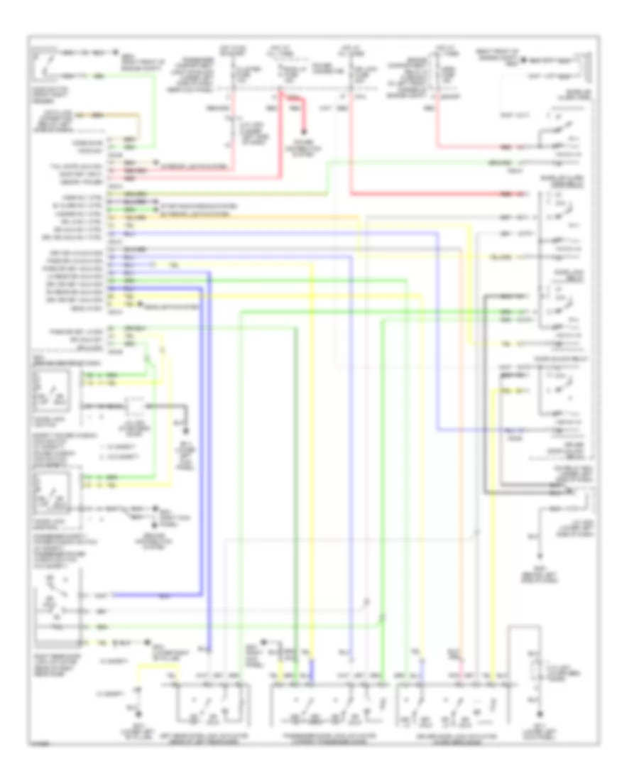
Forced Entry Wiring Diagram for Hyundai Elantra Touring SE 2010
List of elements for Forced Entry Wiring Diagram for Hyundai Elantra Touring SE 2010:
- (right front of engine compt) ge24
- 87a
- B/ alarm rly ctrl
- Bcm (behind center of dash)
- Burglar alarm horn
- Burglar alarm horn relay
- Cluster fuse 10a
- Code save
- Data link connector (below left side of dash)
- Door lock relay
- Door lock switch
- Door unlock relay
- Dr lk
- Dr lk rly ctrl
- Dr lk sw
- Dr lock fuse 20a
- Dr unlk
- Dr unlk rly ctrl
- Dr unlk sw
- Driver door lock actuator (in driver's door)
- Driver door unlock relay
- Drv dr key unlk sig
- Drv dr lk/unlk sig
- Drv dr unlk rly ctrl
- E/r-frt
- Engine compartment relay & fuse box (in left front corner of engine compt)
- Exterior lights system
- Ge24 (right front of engine compt)
- Gf11 (lower left kick panel)
- Gf21 (right kick panel)
- Gf31 (lower left "b" pillar)
- Gf41 (lower right "b" pillar)
- Gm21 (behind left side of dash)
- Ground distribution system
- Hazard rly ctrl
- Head lp sw
- Headlights system
- Hood sw
- Hood switch (front right fender)
- Horn fuse 15a
- Horn rly ctrl
- Hot at all times
- Hot in on or start
- I/p-a
- I/p-c
- Icm relay box (under left side of dash)
- Interior lights system
- J/c jd01 (in driver's door)
- J/c jm03 (under left side of dash)
- J/c jm04 (lower left side of dash)
- Key lk
- Key unlk
- Left rear door lock actuator (rear of left rear door)
- Lh rear dr unlk sig
- M04-a
- M04-b
- M04-c
- M08-a
- M08-b
- Memory power
- Nca
- On/start input
- Pass dr key lk sig
- Pass dr key unlk sig
- Pass dr lk/unlk sig
- Passenger compartment junction block (under left side of dash, near kick panel)
- Passenger door lock actuator (in front passenger door)
- Passenger safety power window switch (w/ safety) passenger power window switch (w/o safety)
- Pnk
- Power connector
- Power distribution system
- Red
- Rh rear dr unlk sig
- Right rear door lock actuator (rear of right rear door)
- Room lp fuse 15a
- Safety power window main switch (w/ safety) power window main switch (w/o safety)
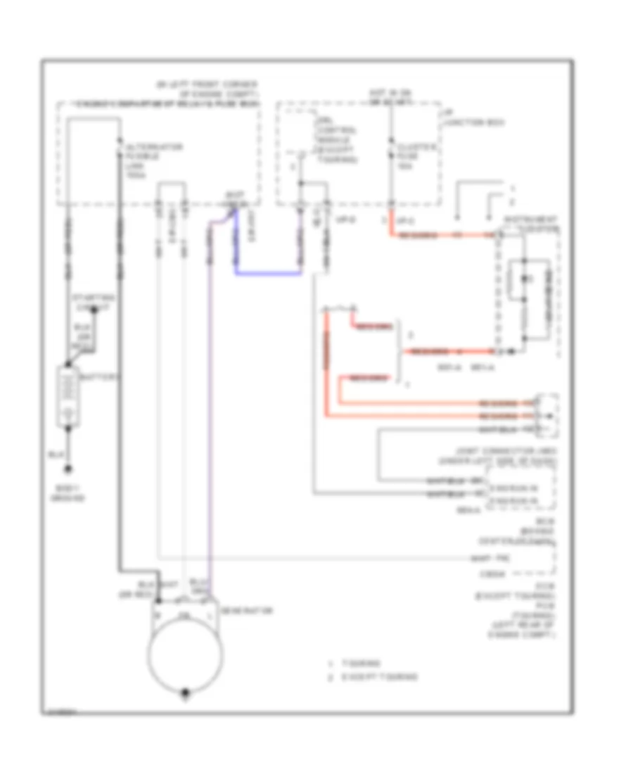
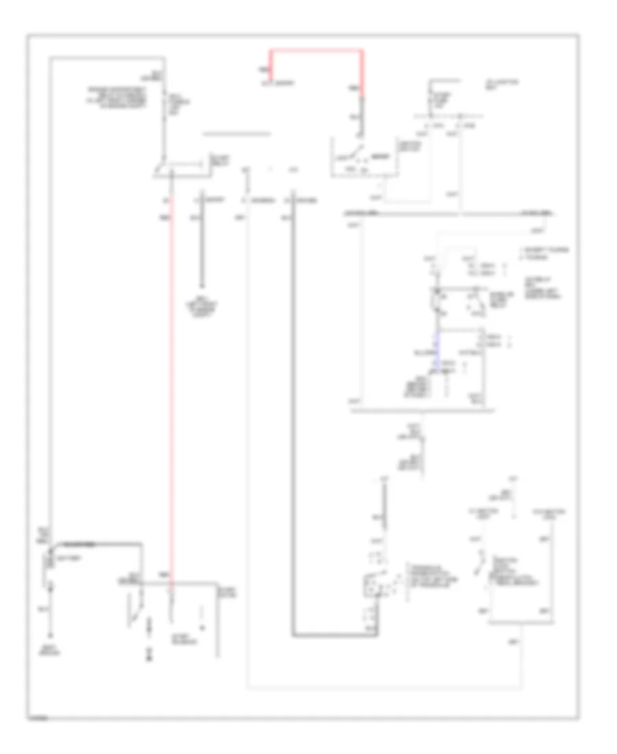
- Starting/charging system
- Tail gate unlk sw
- W/ safety
- W/o safety
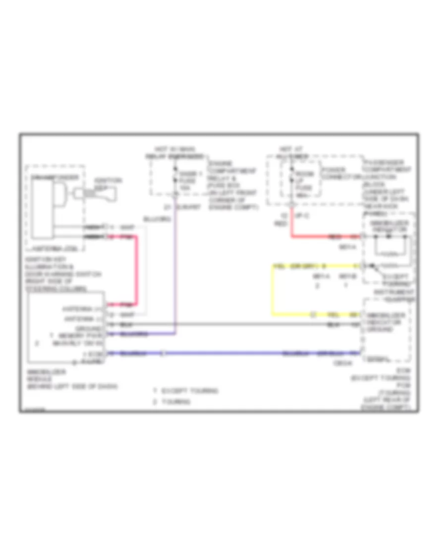
Immobilizer Wiring Diagram for Hyundai Elantra Touring SE 2010
List of elements for Immobilizer Wiring Diagram for Hyundai Elantra Touring SE 2010:
- Antenna (+)
- Antenna (-)
- Antenna coil
- Cbg-k
- E/r-frt
- Ecm (except touring) pcm (touring) (left rear of engine compt)
- Ecm k-line
- Engine compartment relay & fuse box (in left front corner of engine compt)
- Except touring
- Ground memory pwr main rly 'on' in
- Hot at all times
- Hot w/ main relay energized
- I/p-c
- Ignition key
- Ignition key illumination & door warning switch (right side of steering column)
- Immobilizer indicator
- Immobilizer indicator ground
- Immobilizer module (behind left side of dash)
- Instrument cluster
- M01-a
- M01-b
- Nca
- Passenger compartment junction block (under left side of dash, near kick panel)
- Pnk
- Power connector
- Red
- Room lp fuse 15a
- Signal
- Snsr 1 fuse 10a
- Touring
- Transponder
BODY CONTROL MODULES
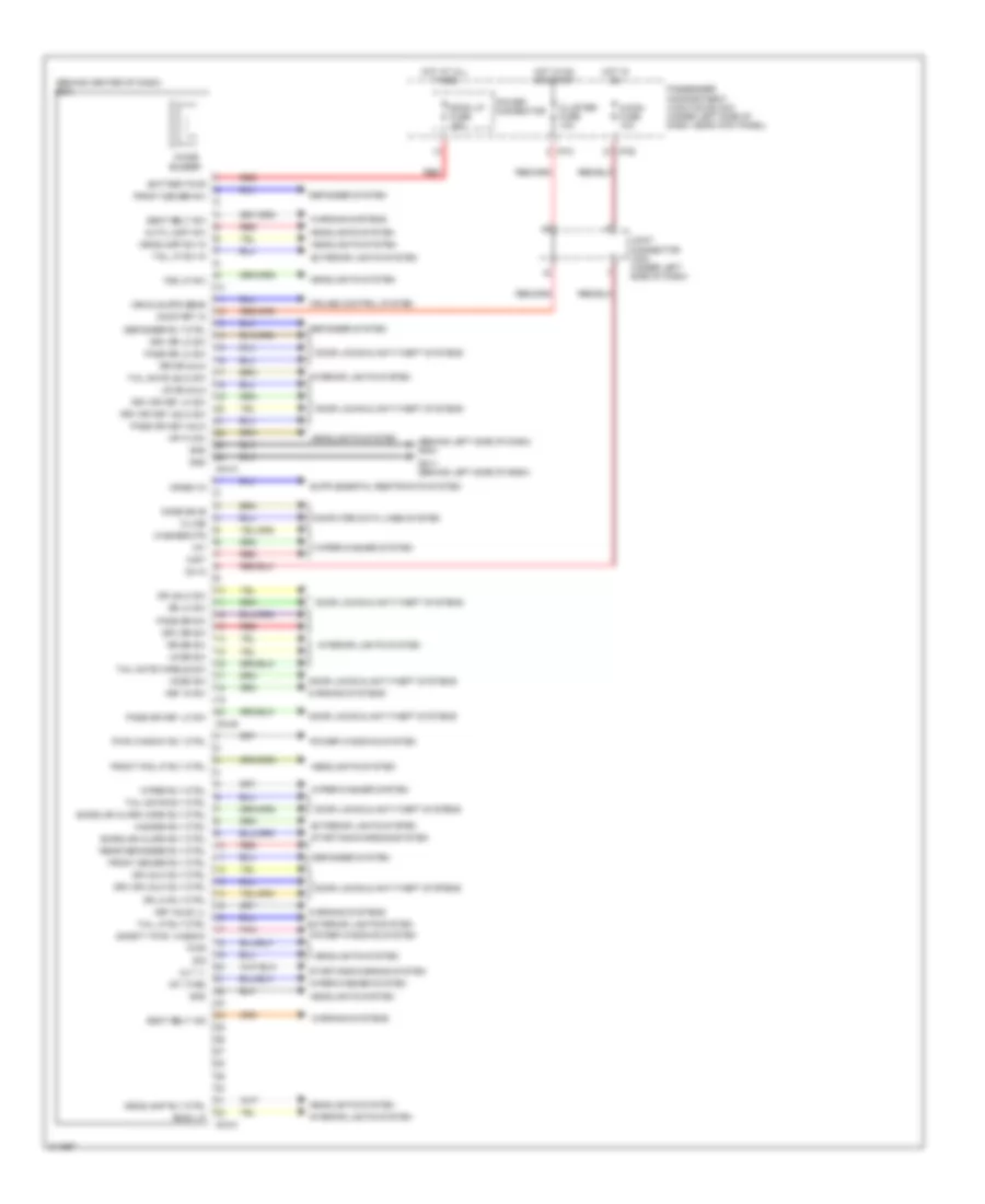
Body Control Modules Wiring Diagram for Hyundai Elantra Touring SE 2010
List of elements for Body Control Modules Wiring Diagram for Hyundai Elantra Touring SE 2010:
- (behind center of dash) bcm
- (behind left side of dash) gm21
- A/con fuse 10a
- Alt "l"
- Auto light sw
- Battery pwr
- Burglar alarm horn rly ctrl
- Burglar alarm rly ctrl
- Chime buzzer
- Cluster fuse 10a
- Code save
- Computer data lines system
- Crash in
- Cruise control system
- Defogger rly ctrl
- Defogger system
- Door locks & anti-theft systems
- Dr lk rly ctrl
- Dr lk sw
- Dr unlk rly ctrl
- Dr unlk sw
- Drv dr key lk sw
- Drv dr key unlk sw
- Drv dr lk sw
- Drv dr sw
- Drv dr unlk rly ctrl
- Exterior lights system
- Fog lp sw
- Front deicer rly ctrl
- Front deicer sw
- Front fog lp rly ctrl
- Gm11 (behind left side of dash)
- Gnd
- H/p hi sw
- Hazard rly ctrl
- Headlamp rly ctrl
- Headlamp sw in
- Headlights system
- Hood sw
- Hot at all times
- Hot in on
- Hot in on or start
- I/p-b
- I/p-c
- Int
- Int (time)
- Interior lights system
- Joint connector jm03 (under left side of dash)
- K-line
- Key hole ill
- Key in sw
- Lr dr sw
- Lr dr unlk
- M04-a
- M04-b
- M04-c
- Mist
- On in
- On/start in
- Pass dr key lk sw
- Pass dr key unlk
- Pass dr lk sw
- Pass dr sw
- Passenger compartment junction block (under left side of dash, near kick panel)
- Pnk
- Power connector
- Power windows system
- Pwr
- Pwr window rly ctrl
- Rear defogger rly ctrl
- Red
- Room lp
- Room lp fuse 15a
- Rr dr sw
- Rr dr unlk
- Safety pwr window
- Seat belt ind
- Seat belt sw
- Sig
- Starting/charging system
- Tail gate handle sw
- Tail gate rly ctrl
- Tail gate unlk sw
- Tail lp rly ctrl
- Tail lp sw in
- Vehicle spd sens
- Warning systems
- Washer mtr
- Wiper rly ctrl
- Wiper/washer system
COMPUTER DATA LINES
Computer Data Lines Wiring Diagram for Hyundai Elantra Touring SE 2010
List of elements for Computer Data Lines Wiring Diagram for Hyundai Elantra Touring SE 2010:
- (behind left side of dash) gm11
- (below left side of dash) eps control module
- (left rear of engine compt) ge22
- (left rear of engine compt) ge23
- (not used)
- (under center console) srs control module
- A/c control module (automatic a/c) (below center of dash)
- A/t
- Abs 1 fusible link 40a
- Abs 2 fusible link 20a
- Abs control module (left rear of engine compt)
- Abs fuse 10a
- Atm key lock control module (behind left center of dash)
- Audio
- Bcm (behind center of dash)
- Can hi
- Can high
- Can ic
- Can lo
- Can low
- Cbg-a
- Cbg-k
- Code save
- Cruise control module (on right fender)
- Data link connector (dlc) (below left side of dash)
- Diagnosis
- E/r-erom
- Engine compartment relay & fuse box (in left front corner of engine compt)
- Esc control module (left rear of engine compt)
- Gm21
- Hot at all times
- Hot in on or start
- I/p-c
- I/p-d
- I/p-e
- Instrument cluster
- J/c je01
- J/c jm02 (lower left side of dash)
- J/c jm04 (lower left side of dash)
- K-line
- M/t
- M01-a
- M04-a
- M04-b
- M05-a
- M05-b
- M49
- M76-a
- Micom
- Multipurpose check connector
- Nca
- Passenger compartment junction block (under left side of dash, near kick panel)
- Pcm (left rear of engine compt)
- Pnk
- Power connector
- Power distribution system
- Red
- Room lp fuse 15a
- Spd sig
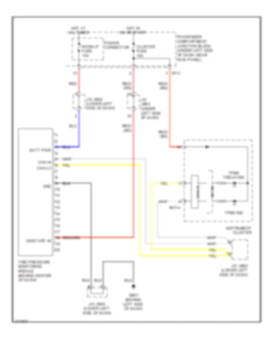
- Tire pressure monitoring module (behind center of dash)
- Veh spd
- Vehicle spd in
- Vehicle spd out
- Vehicle spd sig
- Vehicle speed sensor (on top of transaxle)
- Vss
- W/ esc
- W/o esc
- Yaw rate sensor (below center console)
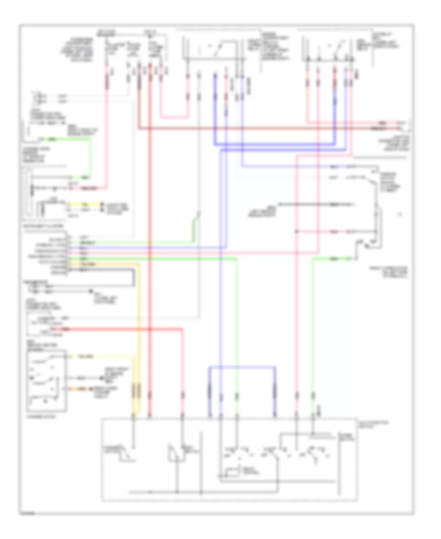
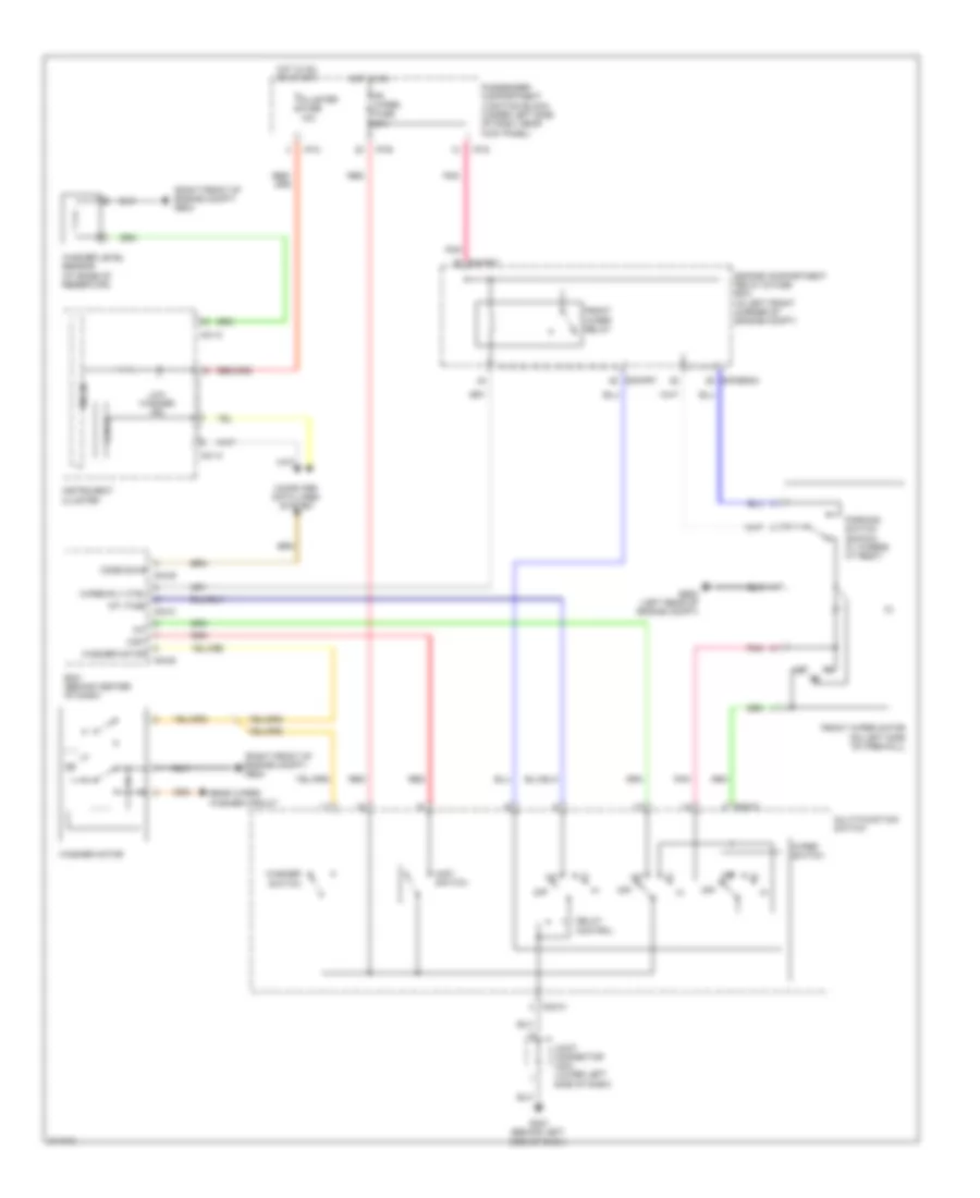
COOLING FAN
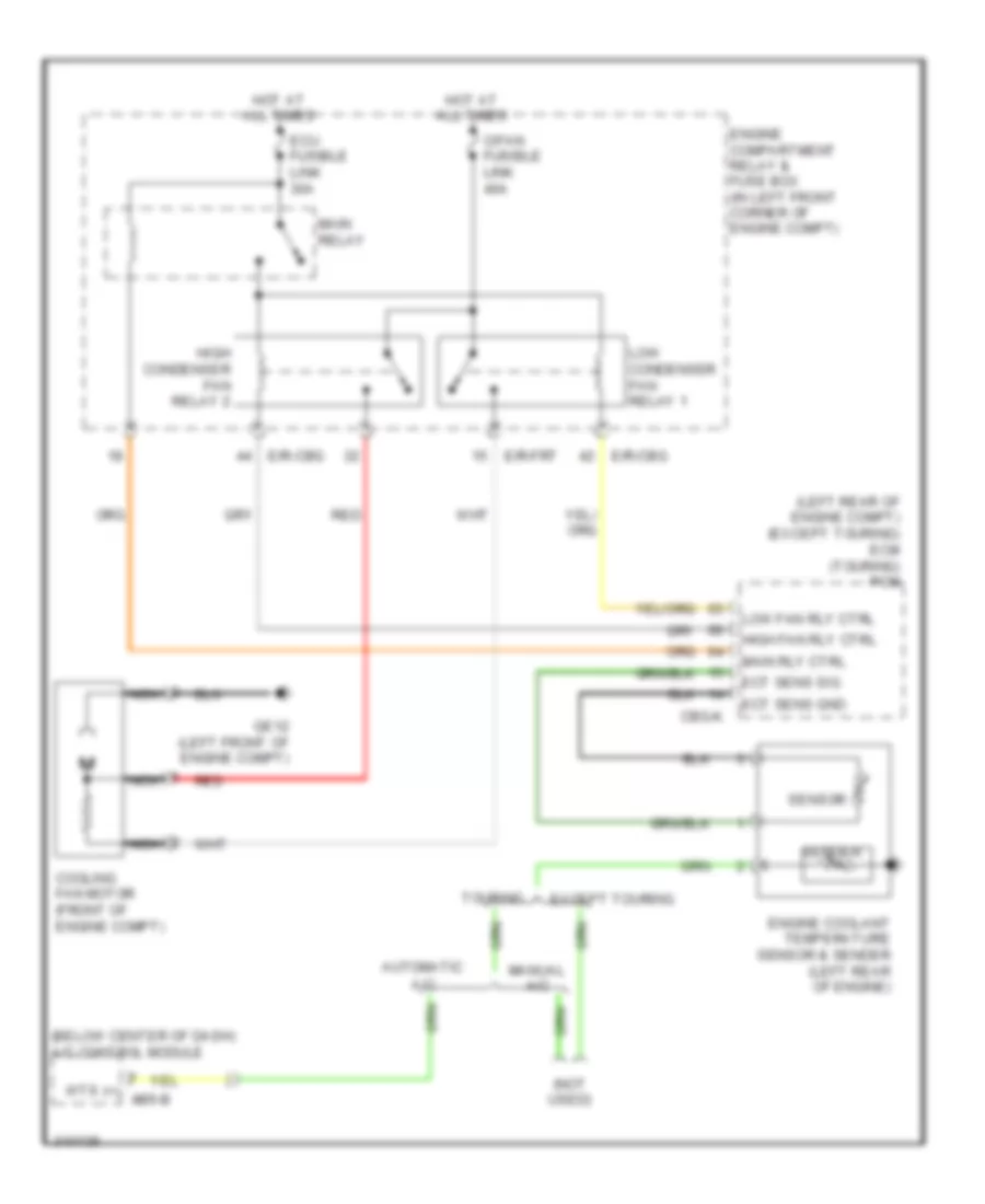
Cooling Fan Wiring Diagram for Hyundai Elantra Touring SE 2010
List of elements for Cooling Fan Wiring Diagram for Hyundai Elantra Touring SE 2010:
- (below center of dash) a/c control module
- (left rear of engine compt) (except touring) ecm (touring) pcm
- (not used)
- Automatic a/c
- C/fan fusible link 40a
- Cbg-k
- Cooling fan motor (front of engine compt)
- E/r-cbg
- E/r-frt
- Ect sens gnd
- Ect sens sig
- Ecu fusible link 30a
- Engine compartment relay & fuse box (in left front corner of engine compt)
- Engine coolant temperature sensor & sender (left rear of engine)
- Except touring
- Ge12 (left front of engine compt)
- High condenser fan relay 2
- High fan rly ctrl
- Hot at all times
- Low condenser fan relay 1
- Low fan rly ctrl
- Main relay
- Main rly ctrl
- Manual a/c
- Nca
- Red
- Sender
- Sensor
- Touring
- Wts (+) m05-b
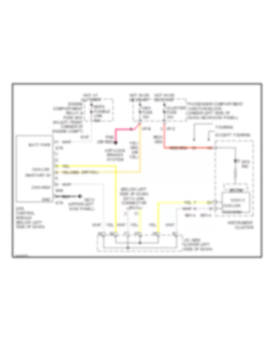
CRUISE CONTROL
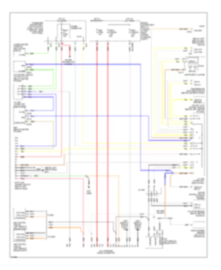
Cruise Control Wiring Diagram for Hyundai Elantra Touring SE 2010
List of elements for Cruise Control Wiring Diagram for Hyundai Elantra Touring SE 2010:
- (+)
- (-)
- (left rear of engine compt)
- (left rear of engine compt) abs control module
- (on top of transaxle) (m/t) vehicle speed sensor
- 2 or l sig
- A/c control module (automatic a/c) (below center of dash)
- A/c control module (automatic a/c) (below center of dash, forward of shift lever)
- A/t
- Actuator clutch
- Amp (right side of trunk)
- Atm key lock control module (behind left center of dash)
- Audio
- B/up fuse 10a
- Bcm (behind center of dash)
- Cancel
- Cbg-a
- Cbg-k
- Clock spring
- Cluster fuse 10a
- Coast set
- Cruise clutch pedal position switch (near clutch pedal bracket)
- Cruise control module (on right fender)
- Cruise ind
- Cruise indicator
- Cruise remocon switch
- Cruise set ind
- Data link connector (below left side of dash)
- E/r-cbg
- E/r-erom
- Ecm (except touring) pcm (touring)
- Ecu 2 fuse 10a
- Engine compartment relay & fuse box (in left front corner of engine compt)
- Esc control module
- Except touring
- Exterior lights system
- F23-a
- Fuel sender & fuel pump motor (except touring) (below center of rear seat)
- Gbg11
- Gbg13
- Ge22 (left rear of engine compt)
- Ge24 (right front of engine compt)
- Ground
- Hall ic -
- Hot at all times
- Hot in on or start
- I/p-b
- I/p-c
- Ill
- Instrument cluster
- Interior lights system
- J/c jm02 (lower left side of dash)
- M/t
- M01-a
- M01-b
- M01-c
- M02-r
- M04-a
- M04-b
- M05-b
- M54-a
- M76-a
- Micom
- Mm01
- Multi- function switch
- Nca
- O/d control
- O/d request
- On/off
- On/off sig
- On/start
- On/start input
- Park/neutral input
- Passenger compartment junction block (under left side of dash, near kick panel)
- Pnk
- Red
- Res accel
- Right front wheel sensor (w/o abs/esc) (top of strut tower)
- Set indicator
- Signal
- Snsr 2 fuse 10a
- Spd in (+)
- Spd in (-)
- Spd sig
- Steering wheel
- Stop fuse 15a
- Stop lamp sw input
- Stop lamp switch (on brake pedal bracket)
- Tcm (except touring) pcm (touring) (left rear of engine compt)
- Tire pressure monitoring module (except touring) (behind center of dash)
- Touring
- Veh spd
- Veh spd out
- Vehicle speed input
- W/ amp
- W/ esc
- W/o amp
- W/o esc
DEFOGGERS
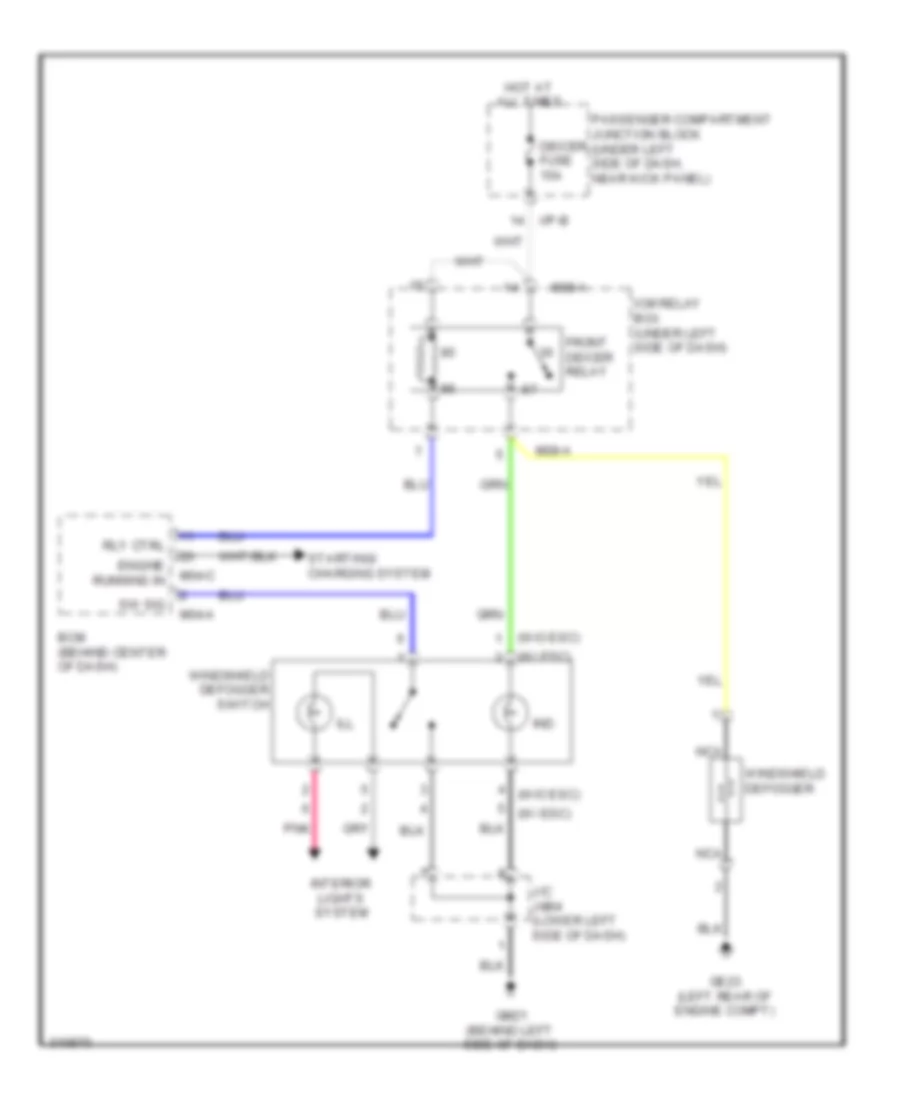
Front Deicer Wiring Diagram for Hyundai Elantra Touring SE 2010
List of elements for Front Deicer Wiring Diagram for Hyundai Elantra Touring SE 2010:
- (w/ esc)
- (w/o esc)
- Bcm (behind center of dash)
- Deicer fuse 15a
- Engine running in
- Front deicer relay
- Ge23 (left rear of engine compt)
- Gm21 (behind left side of dash)
- Hot at all times
- I/p-b
- Icm relay box (under left side of dash)
- Ill
- Ind
- Interior lights system
- J/c jm04 (lower left side of dash)
- M04-a
- M04-c
- M08-a
- Nca
- Passenger compartment junction block (under left side of dash, near kick panel)
- Pnk
- Rly ctrl
- Starting/ charging system
- Sw sig
- Windshield defogger
- Windshield defogger switch
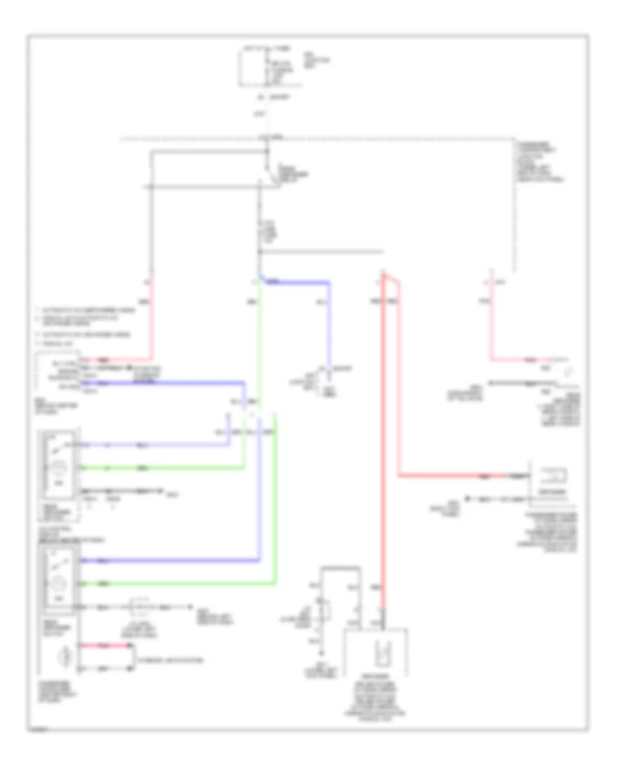
Rear Defogger & Heated Mirrors Wiring Diagram for Hyundai Elantra Touring SE 2010
List of elements for Rear Defogger & Heated Mirrors Wiring Diagram for Hyundai Elantra Touring SE 2010:
- (advanced a/bag)
- (not used)
- A/c control module (below center of dash)
- Automatic a/c (advanced a/bag)
- Automatic a/c (depowered a/bag)
- Bcm (behind center of dash)
- Defogger
- Driver power outside mirror (automatic a/c) driver power outside mirror & mirror folding motor (manual a/c)
- E/r junction box
- E/r-frt
- Engine running in
- Gf11 (lower left kick panel)
- Gf21 (right kick panel)
- Gm21 (behind left side of dash)
- Gm31
- Gr21 (middle right of tail gate)
- Hot at all times
- Htd mirr fuse 10a
- I/p-b
- I/p-f
- I/p-g
- Ind
- Interior lights system
- J/c jd01 (in driver's door)
- J/c jm04 (lower left side of dash)
- M04-a
- M04-c
- M05-a
- M06-b
- Manual a/c
- Manual a/c & automatic a/c
- Nca
- Passenger air bag sbr (center right of dash)
- Passenger compartment junction block (under left end of dash near kick panel)
- Passenger power outside mirror (automatic a/c) passenger power outside mirror & mirror folding motor (manual a/c)
- Pnk
- R23
- R29
- Rear defogger (+: right side of rear window) (-: left side of rear window)
- Rear defogger relay
- Rear defogger switch
- Red
- Rly ctrl
- Rr htd fusible link 40a
- Starting/ charging system
- Sw sig
ELECTRONIC POWER STEERING
Electronic Power Steering Wiring Diagram for Hyundai Elantra Touring SE 2010
List of elements for Electronic Power Steering Wiring Diagram for Hyundai Elantra Touring SE 2010:
- (below left side of dash) data link connector (dlc)
- Anti-lock brakes system
- Batt pwr
- Can high
- Can i.c
- Can low
- Cluster fuse 10a
- E78
- E79
- Engine compartment relay & fuse box (in left front corner of engine compt)
- Eps control module (below left side of dash)
- Eps ind
- Except touring
- Ge13 (upper left kick panel)
- Gnd
- Hot at all times
- Hot in on or start
- I/p-b
- I/p-c
- Ign1 fuse 15a
- Instrument cluster
- J/c jm02 (lower left side of dash)
- M01-a
- M49
- Mdps fusible link 80a
- Micom
- On/start in
- Passenger compartment junction block (under left side of dash, near kick panel)
- Pnk (or red)
- Touring
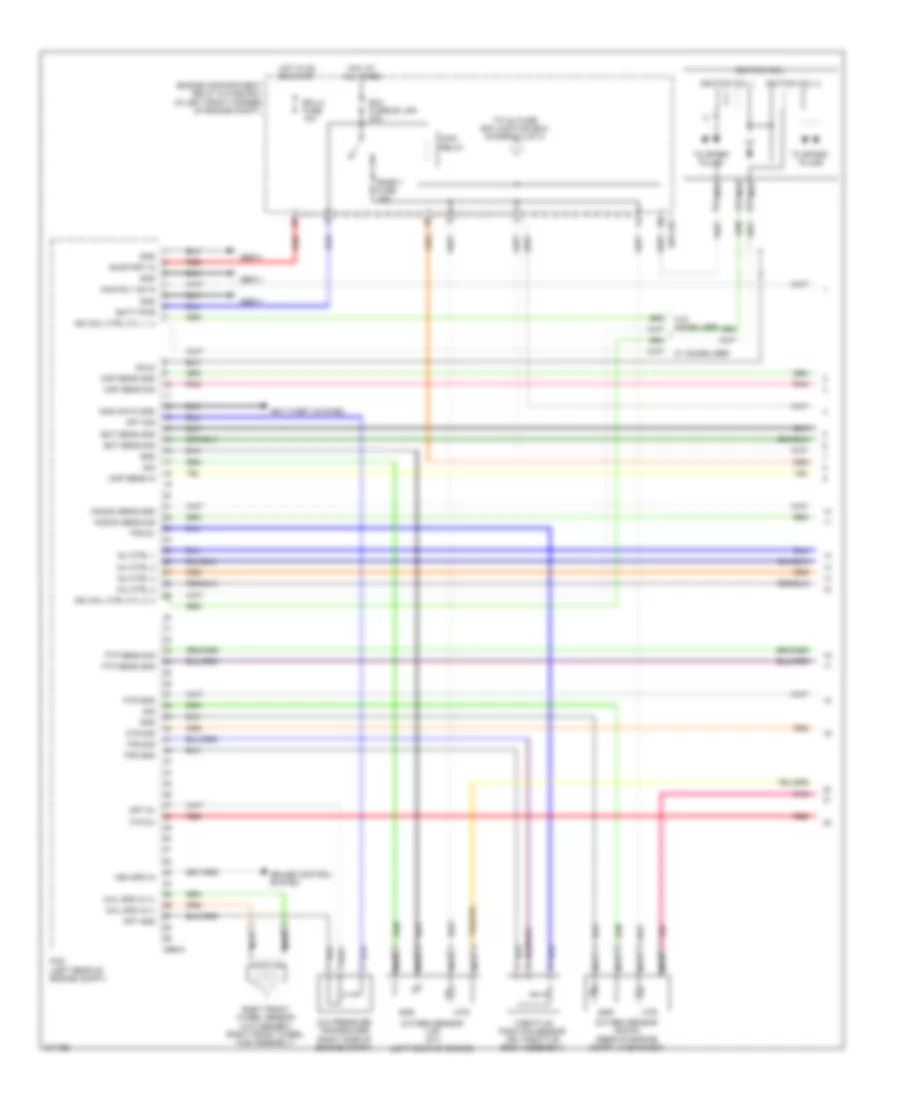
ENGINE PERFORMANCE
2.0L
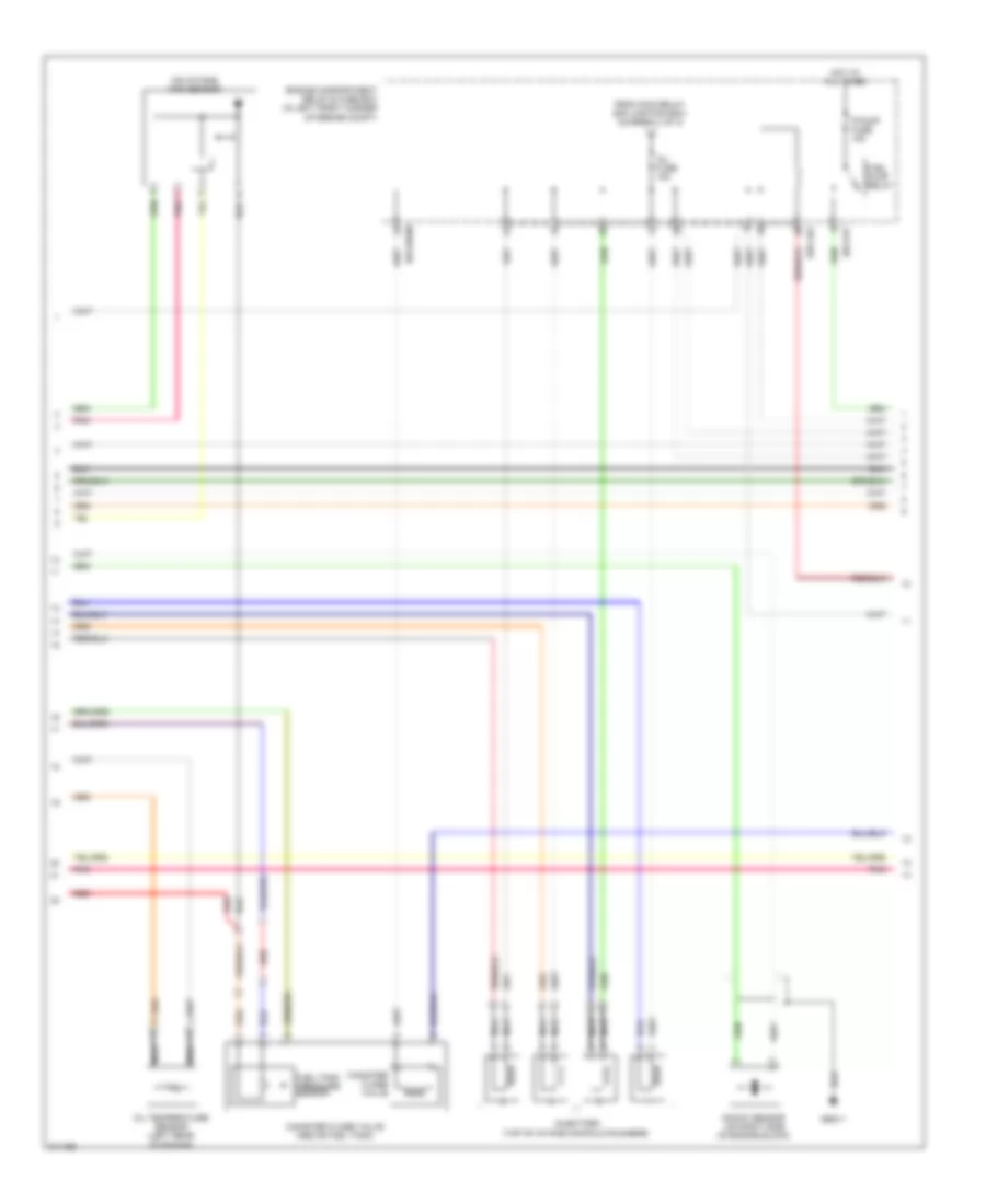
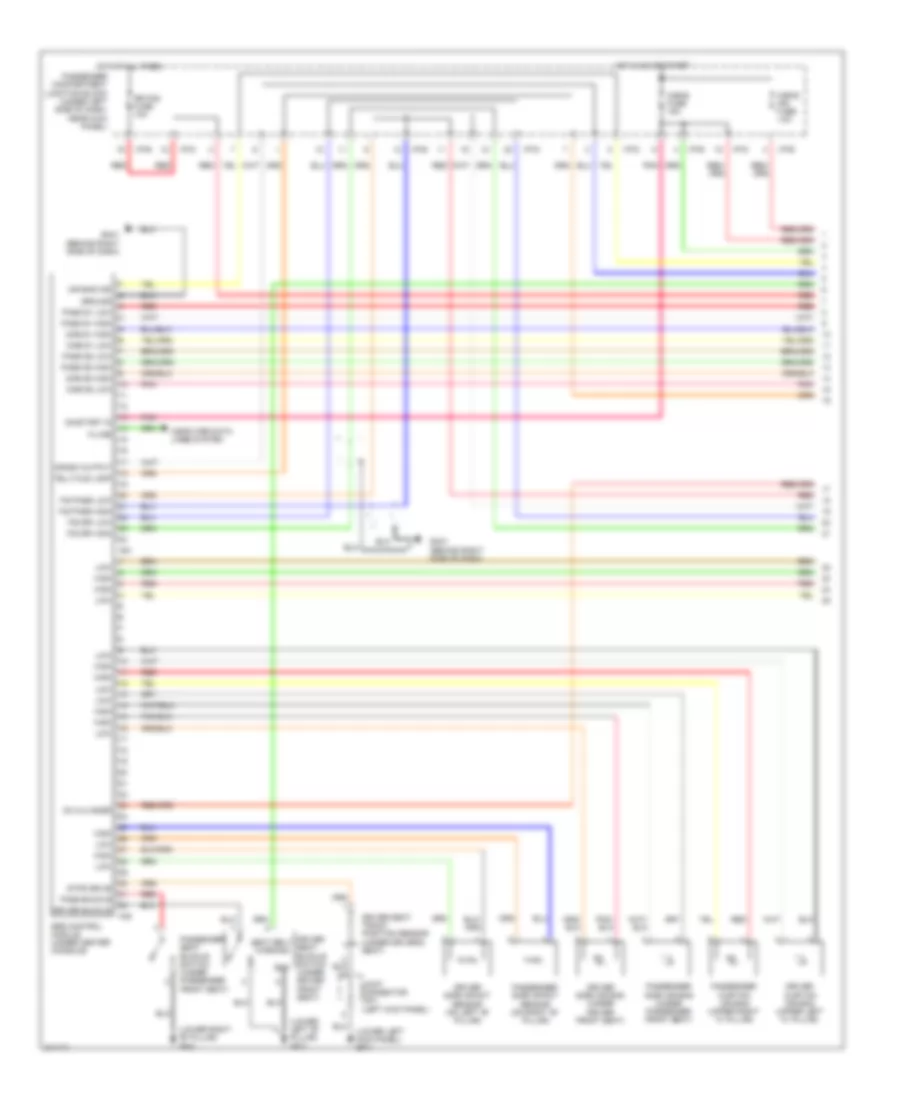
2.0L, Engine Performance Wiring Diagram (1 of 5) for Hyundai Elantra Touring SE 2010
List of elements for 2.0L, Engine Performance Wiring Diagram (1 of 5) for Hyundai Elantra Touring SE 2010:
- A/c pressure transducer (right side of engine compt)
- Anti-theft system
- Apt 5v
- Apt gnd
- Apt sig
- Batt pwr
- Cbg-k
- Cruise control system
- E/r-cbg
- Ect sens gnd
- Ect sens sig
- Ecu 2 fuse 10a
- Ecu fusible link 30a
- Engine compartment relay & fuse box (in left front corner of engine compt)
- Ftp 5v
- Ftp sens gnd
- Ftp sens sig
- Gbg11
- Gnd
- Hot at all times
- Hot in on or start
- Htr
- Ign coil ctrl cyl 1, 4
- Ign coil ctrl cyl 2, 3
- Ignition coil
- Ignition coil 1
- Ignition coil 2
- Immo data gnd
- Inj ctrl 1
- Inj ctrl 2
- Inj ctrl 3
- Inj ctrl 4
- Knock sens gnd
- Knock sens sig
- Main relay
- Main rly on in
- Map sens gnd
- Map sens in
- Map sens sig
- Nca
- On/start in
- Ots gnd
- Ots sig
- Oxygen sensor (down) (rear of engine compt, in exhaust)
- Oxygen sensor (up) (a/t) (left rear of engine)
- Pcm (left rear of engine compt)
- Pnk
- Red
- Right front wheel sensor (w/o abs/esc) (right front wheel hub assembly)
- Shld
- Sig
- Snr
- Snsr 1 fuse 10a
- Throttle position sensor (on throttle body assembly)
- To inj fuse e/r junction box (diagram 2 of 3)
- To spark plugs
- Tps 5v
- Tps gnd
- Tps sig
- Veh spd in
- W/ immobilizer
- W/o immobilizer
- Whl spd in (+)
- Whl spd in (-)
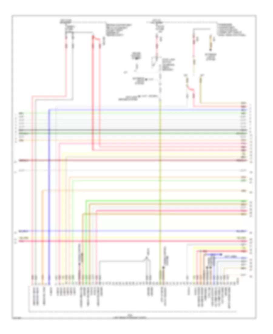
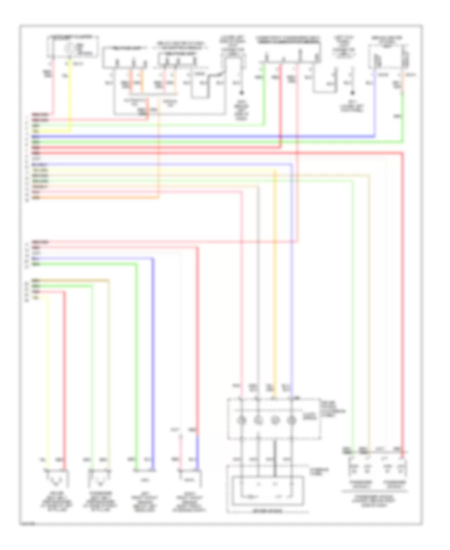
2.0L, Engine Performance Wiring Diagram (2 of 5) for Hyundai Elantra Touring SE 2010
List of elements for 2.0L, Engine Performance Wiring Diagram (2 of 5) for Hyundai Elantra Touring SE 2010:
- (on intake) map sensor
- Canister close valve
- Canister close valve (above fuel tank)
- E/r-cbg
- E/r-erom
- E/r-frt
- Engine compartment relay & fuse box (in left front corner of engine compt)
- F/pump fuse 15a
- From main relay e/r junction box (diagram 1 of 3)
- Fuel pump relay
- Fuel tank pressure sensor
- Gbg11
- Hot at all times
- Inj fuse 15a
- Injectors (top of intake manifold runners)
- Knock sensor (on right side of engine block)
- Nca
- Oil temperature sensor (left rear of engine)
- Pnk
- Red
2.0L, Engine Performance Wiring Diagram (3 of 5) for Hyundai Elantra Touring SE 2010
List of elements for 2.0L, Engine Performance Wiring Diagram (3 of 5) for Hyundai Elantra Touring SE 2010:
- (not used)
- 2 input
- 2 or l sig
- 3 input
- A/t
- Anti-lock brakes system
- Cbg-a
- Cruise control system
- Cruise on/off sig
- D input
- E/r-cbg
- Engine compartment relay & fuse box (in left front corner of engine compt)
- Exterior lights system
- Gbg12
- Ground
- Hot at all times
- Hot in on or start
- I/p-b
- I/p-d
- I/p-f
- Input speed sens
- L input
- Linear sol pwr
- Linear solenoid
- M/t
- N input
- Od off request
- Oil temp sens (+)
- Oil temp sens (-)
- On/off solenoid
- On/start input
- Out spd sens
- P input
- Passenger compartment junction block (under left side of dash, near kick panel)
- Pcm (left rear of engine compt)
- Pcsv-a
- Pcsv-b
- Pcsv-c
- Pcsv-d
- Pnk
- Pwm signal
- R input
- Red
- Snsr 2 fuse 10a
- Solenoid power
- Stop fuse 15a
- Stop lamp switch (on brake pedal bracket)
- Stp lp sw in
- System control cruise
- System cruise control
- Veh spd output
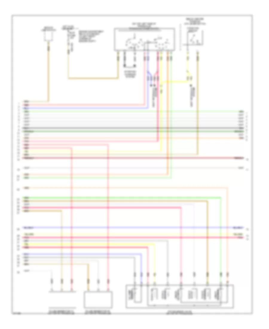
2.0L, Engine Performance Wiring Diagram (4 of 5) for Hyundai Elantra Touring SE 2010
List of elements for 2.0L, Engine Performance Wiring Diagram (4 of 5) for Hyundai Elantra Touring SE 2010:
- (below center console) atm lever switch
- (on top left side of transaxle) transaxle range switch
- 24 brake pcsv-b
- 3 position switch
- Atm solenoid valve (on top of transaxle)
- B/up fuse 10a
- Backup lamp switch
- E/r-cbg
- Engine compartment relay & fuse box (in left front corner of engine compt)
- Hot in on or start
- Linear solenoid
- Oil temp sensor
- Pcsv-a od & lr
- Pcsv-c ud
- Pcsv-d dccsv
- Pnk
- Pulse generator "a" (on top of transaxle)
- Pulse generator "b" (on top of transaxle)
- Red
- Shift interlock system
- Solenoid on/off
- Starting/ charging system
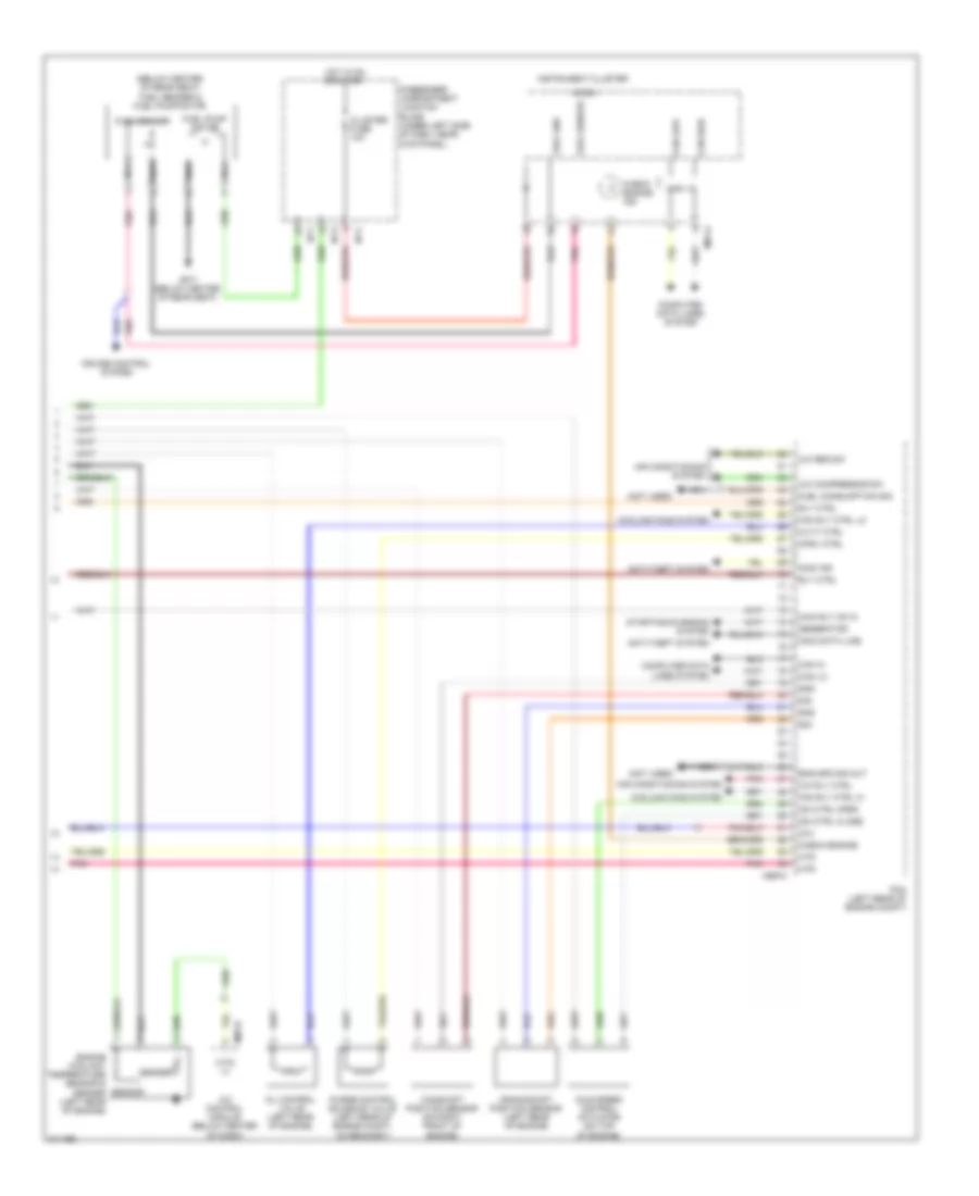
2.0L, Engine Performance Wiring Diagram (5 of 5) for Hyundai Elantra Touring SE 2010
List of elements for 2.0L, Engine Performance Wiring Diagram (5 of 5) for Hyundai Elantra Touring SE 2010:
- (below center of rear seat) fuel sender & fuel pump motor
- (not used)
- A/c compressor sw
- A/c control module (below center of dash)
- A/c req sw
- A/c rly ctrl
- Air conditioning system
- Anti-theft system
- Camshaft position sensor (on right front of engine)
- Can hi
- Can high
- Can i.c
- Can lo
- Can low
- Cbg-k
- Ccv
- Check engine
- Check engine ind
- Cluster fuse 10a
- Computer data lines system
- Cooling fans system
- Cpsv ctrl
- Crankshaft position sensor (left rear of engine)
- Cruise control system
- Cvvt ctrl
- Eng spd sig out
- Engine coolant temperature sensor & sender (left rear of engine)
- Fan rly ctrl hi
- Fan rly ctrl lo
- Fuel consumption sig
- Fuel gnd
- Fuel pump motor
- Fuel sender
- Generator
- Gf71 (below center of rear seat)
- Gnd
- Hot in on or start
- Htr
- I/p-c
- I/p-f
- I/p-g
- Idle speed control actuator (on top of engine)
- Immo data line
- Immo ind
- Instrument cluster
- Isa ctrl close
- Isa ctrl open
- M01-a
- M05-b
- Main rly on in
- Micom
- Nca
- Oil control valve (left rear of engine)
- Passenger compartment junction block (under left side of dash, near kick panel)
- Pcm (left rear of engine compt)
- Pnk
- Purge control solenoid valve (left rear of engine compt, on bracket)
- Rly ctrl
- Sender
- Sensor
- Sig
- Starting/charging system
- Wts (+)
EXTERIOR LIGHTS
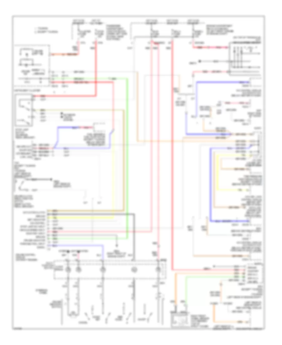
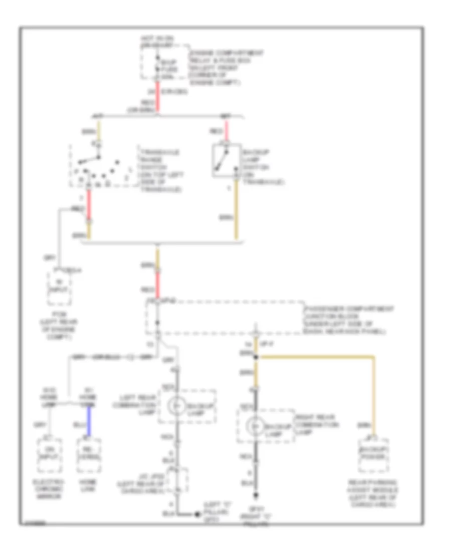
Backup Lamps Wiring Diagram for Hyundai Elantra Touring SE 2010
List of elements for Backup Lamps Wiring Diagram for Hyundai Elantra Touring SE 2010:
- 'r' input
- (left "c" pillar) gf51
- A/t
- B/up fuse 10a
- Backup lamp
- Backup lamp switch (on transaxle)
- Backup power
- Cbg-a
- E/r-cbg
- Electro- chromic mirror
- Engine compartment relay & fuse box (in left front corner of engine compt)
- Gf61 (right "c" pillar)
- Home link
- Hot in on or start
- I/p-d
- I/p-f
- J/c jf02 (left rear of cargo area)
- Left rear combination lamp
- M/t
- Nca
- On input
- Passenger compartment junction block (under left side of dash, near kick panel)
- Pcm (left rear of engine compt)
- Re- verse
- Rear parking assist module (left rear of cargo area)
- Red
- Right rear combination lamp
- Transaxle range switch (on top left side of transaxle)
- W/ home link
- W/o home link
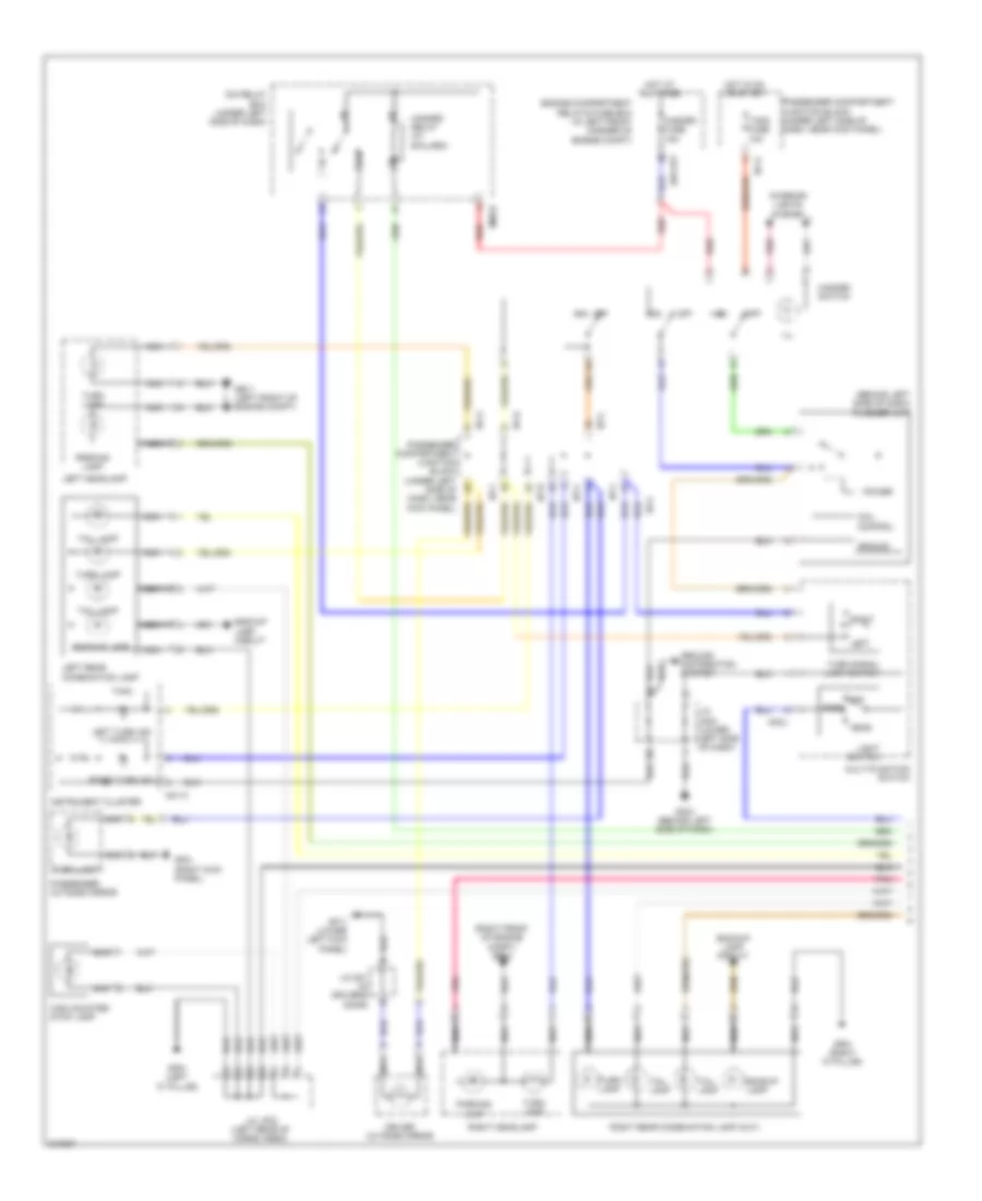
Exterior Lamps Wiring Diagram (1 of 2) for Hyundai Elantra Touring SE 2010
List of elements for Exterior Lamps Wiring Diagram (1 of 2) for Hyundai Elantra Touring SE 2010:
- (behind left side of dash) flasher unit
- (right front of engine compt) ge24
- 87b
- Backup lamp
- Backup lamp circuit
- Coil control
- Driver outside mirror
- E/r-frt
- Engine compartment relay & fuse box (in left front corner of engine compt)
- Ge11 (left front of engine compt)
- Gf11 (lower left kick panel)
- Gf21 (right kick panel)
- Gf51 (left "c" pillar)
- Gf61 (right "c" pillar)
- Gm21 (behind left side of dash)
- Ground
- Ground distribution system
- Hazard fuse 15a
- Hazard relay (w/ b/alarm)
- Hazard switch
- Head
- High mounted stop lamp
- Hot at all times
- Hot in on or start
- I/p-a
- I/p-b
- I/p-c
- I/p-f
- I/p-g
- Icm relay box (under left side of dash)
- Ill
- Instrument cluster
- Interior lights system
- J/c d01 (in driver's door)
- J/c jf02 (left rear of cargo area)
- J/c jm04 (lower left side of dash)
- Left
- Left headlamp
- Left rear combination lamp
- Left turn ind
- Light switch
- M01-c
- M02-l
- M08-b
- Multi-function switch
- Nca
- Off
- Park
- Parking lamp
- Passenger compartment junction block (under left side of dash, near kick panel)
- Passenger outside mirror
- Pnk
- Power
- Red
- Right
- Right headlamp
- Right rear combination lamp (out)
- Right turn ind
- T/sig fuse 10a
- Tail lamp
- Turn lamp
- Turn signal lamp switch
Exterior Lamps Wiring Diagram (2 of 2) for Hyundai Elantra Touring SE 2010
List of elements for Exterior Lamps Wiring Diagram (2 of 2) for Hyundai Elantra Touring SE 2010:
- A/t
- Abs control module (left rear of engine compt)
- Atm key lock control module (behind left center of dash)
- B+ 1 fusible link 50a
- Bcm (behind center of dash)
- Cbg-a
- Cruise control module (on right fender)
- E/r-erom
- E/r-frt
- Engine compartment relay & fuse box (in left front corner of engine compt)
- Esc control module (left rear of engine compt)
- Ge11 (left front of engine compt)
- Ge24 (right front of engine compt)
- Gr11 (center of tail gate)
- Hazard rly ctrl
- Hot at all times
- Hot in on or start
- I/p-b
- I/p-c
- I/p-d
- I/p-f
- I/p-g
- I/p-h
- J/c jf01 (left kick panel)
- Left side marker lamp
- License lamp
- M/t
- M04-a
- M04-c
- Nca
- Passenger compartment junction block (under left side of dash, near kick panel)
- Pcm (left rear of engine compt)
- Pnk
- Rear side marker lamp
- Red
- Right side marker lamp
- Snsr 2 fuse 10a
- Stop fuse 15a
- Stop lamp switch (on brake pedal bracket)
- Tail gate switch & license lamp
- Tail lamp relay
- Tail lh fuse 10a
- Tail lp rly ctrl
- Tail lp sw in
- Tail rh fuse 10a
- W/ esc
- W/o esc
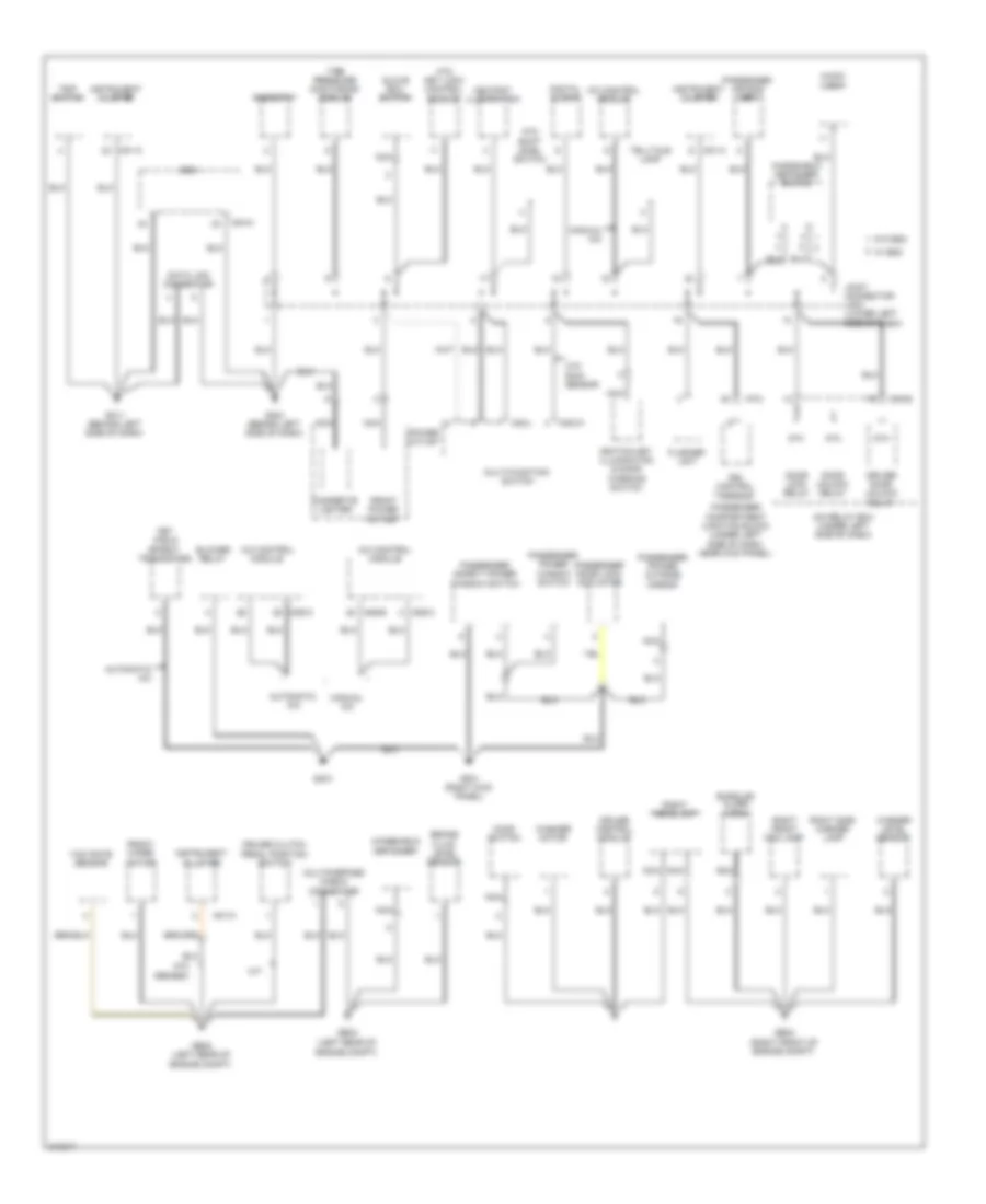
GROUND DISTRIBUTION
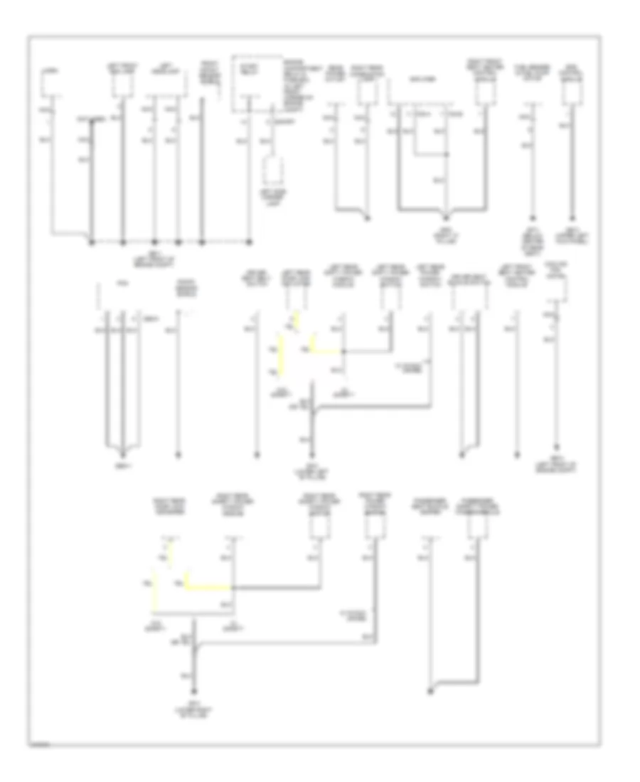
Ground Distribution Wiring Diagram (1 of 3) for Hyundai Elantra Touring SE 2010
List of elements for Ground Distribution Wiring Diagram (1 of 3) for Hyundai Elantra Touring SE 2010:
- 87a
- A/c control module
- Ashtray illumination
- Atm key lock control module
- Atm shift level switch
- Audio jack
- Automatic a/c
- Bcm
- Blower relay
- Brake fluid level sensor
- Burglar alarm horn
- Cigarette lighter
- Cruise clutch pedal position switch
- Cruise control module
- Data link connector
- Digital clock
- Door lock relay
- Door unlock relay
- Driver door unlock relay
- Drl control module
- Engine compt)
- Fet (field effect transistor)
- Flasher unit
- Front power outlet
- Front wiper motor
- Ge22 (left rear of
- Ge23 (left rear of
- Ge24 (right front of engine compt)
- Gf21 (right kick panel)
- Glove box switch
- Gm11 (behind left side of dash)
- Gm21 (behind left side of dash)
- Gm31
- Hood switch
- I/p-c
- Icm relay box (under left side of dash)
- Ignition key illumination & door warning switch
- Instrument cluster
- Joint connector jm04 (lower left side of dash)
- M/t
- M01-a
- M01-c
- M02-l
- M02-w
- M04-a
- M05-a
- M06-a
- M06-b
- M08-b
- Manual a/c
- Multi-function switch
- Multipurpose check connector
- Nca
- Passenger air bag sbr
- Passenger compartment junction block (under left side of dash, near kick panel)
- Passenger door lock actuator
- Passenger power outside mirror
- Passenger power window switch
- Passenger safety power window switch
- Power outlet
- Rheostat
- Right front fog lamp
- Right headlamp
- Right side marker lamp
- Telltale lamp
- Tire pressure monitoring module
- Trip switch
- W/ esc
- W/o abs/esc
- W/o esc
- W/o rain sensor
- Washer level sensor
- Washer motor
- Windshield defogger
- Windshield defogger switch
- Yaw rate sensor
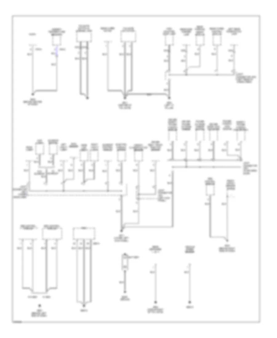
Ground Distribution Wiring Diagram (2 of 3) for Hyundai Elantra Touring SE 2010
List of elements for Ground Distribution Wiring Diagram (2 of 3) for Hyundai Elantra Touring SE 2010:
- (not used)
- Amplifier
- Cbg-k
- Cooling fan motor
- Driver seat belt switch
- Driver seat buckle switch
- E/r-frt
- Engine compartment relay & fuse box (in left front corner of engine compt)
- Eps control module
- F23-a
- F23-b
- Front impact sensor shield
- Fuel sender & fuel pump motor
- Gbg11
- Ge11 (left front of engine compt)
- Ge12 (left front of engine compt)
- Ge13 (upper left kick panel)
- Gf31 (lower left "b" pillar)
- Gf41 (lower right "b" pillar)
- Gf61 (right "c" pillar)
- Gf71 (below center of rear seat)
- Horn
- Knock sensor shield
- Left front fog lamp
- Left front seat heater control module
- Left headlamp
- Left rear door lock actuator
- Left rear power window switch
- Left rear safty power window module
- Left rear safty power window switch
- Left side marker lamp
- Nca
- Passenger safety power window module
- Passenger seat buckle switch
- Pcm
- Rear power outlet
- Right front seat heater control module
- Right rear combination lamp
- Right rear door lock actuator
- Right rear power window switch
- Right rear safety power window module
- Right rear safety power window switch
- Start relay
- W/ p/wdw (fr+rr)
- W/ safety
- W/o safety
Ground Distribution Wiring Diagram (3 of 3) for Hyundai Elantra Touring SE 2010
List of elements for Ground Distribution Wiring Diagram (3 of 3) for Hyundai Elantra Touring SE 2010:
- (behind left end of dash)
- Abs control module
- Ambient temperature sensor 2
- Audio
- Battery
- Body ground
- Cbg-a
- Driver door lock actuator
- Driver power outside mirror
- Driver safety power window module
- Driver seat track position sensor
- Electro- chromic mirror
- Esc control module
- Front impact sensor shield
- Gbg12
- Gbg13
- Ge21
- Gf11 (lower left kick panel)
- Gf51 (left "c" pillar)
- Gm41 (behind right side of dash)
- Gm51 (behind center of dash)
- Gr11 (center of tail gate)
- Gr21 (middle right of tail gate)
- High mounted stop lamp
- Home link ecm
- Joint connector jd01 (in driver's door)
- Joint connector jf01 (left kick panel)
- Joint connector jf02 (left rear of cargo area)
- Joint connector jr01 (under headliner)
- Left rear combination lamp
- Left vanity lamp
- M76-a
- M84-2
- Map lamp
- Nca
- Pcm
- Power outside mirror switch
- Power window main switch
- Rain sensor
- Rear defogger (-)
- Rear parking assist module
- Rear side marker lamp
- Rear wiper control module
- Rear wiper motor
- Right vanity lamp
- Room lamp
- Safety power window main switch
- Srs control module
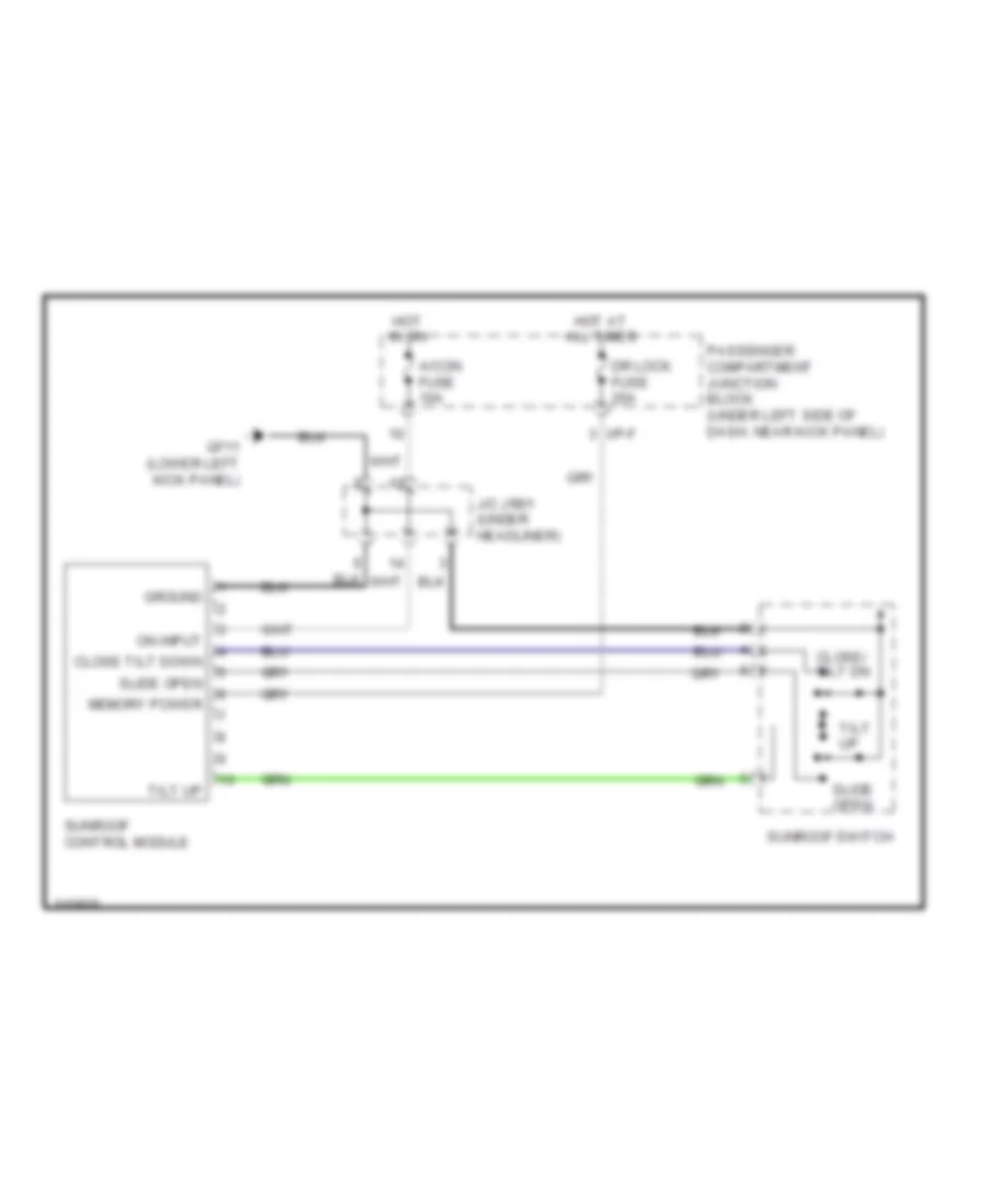
- Sunroof control module
- Sunroof switch
- Tailgate actuator
- Tailgate switch & license lamp
- Vehicle speed sensor
- W/ esc
- W/ sunroof
- W/o esc
- W/o sunroof
- Weight classification sensor
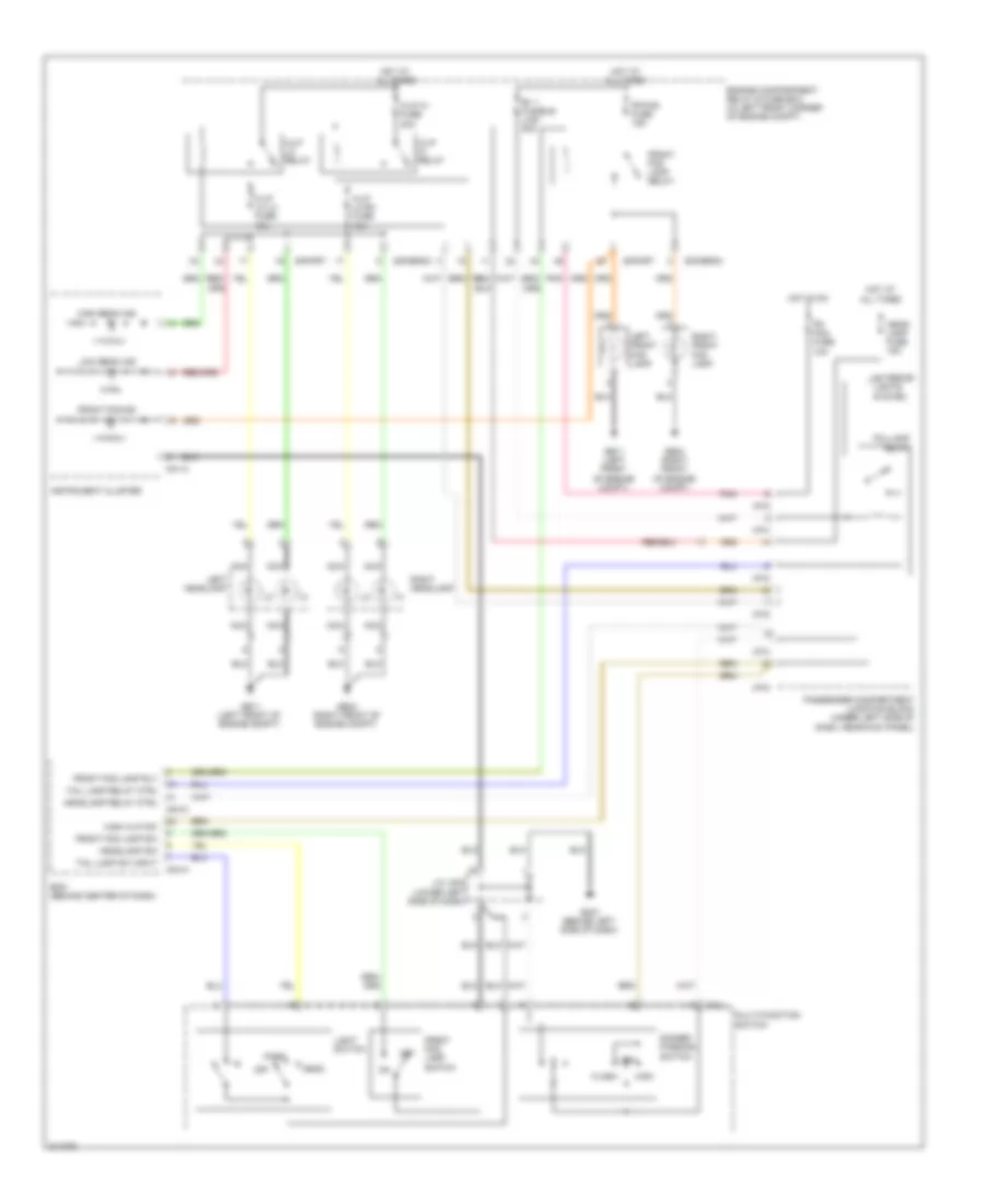
HEADLIGHTS
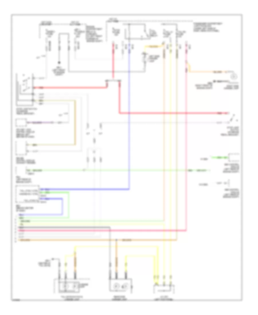
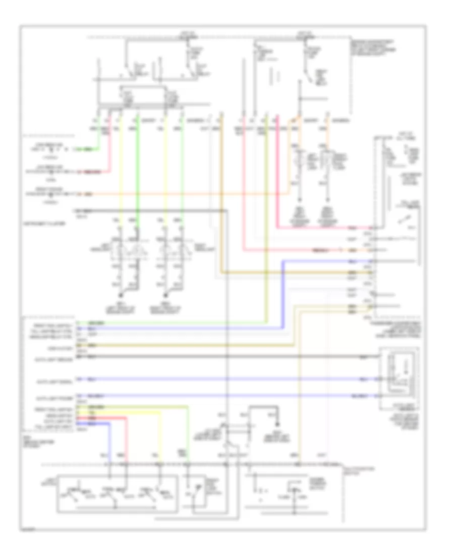
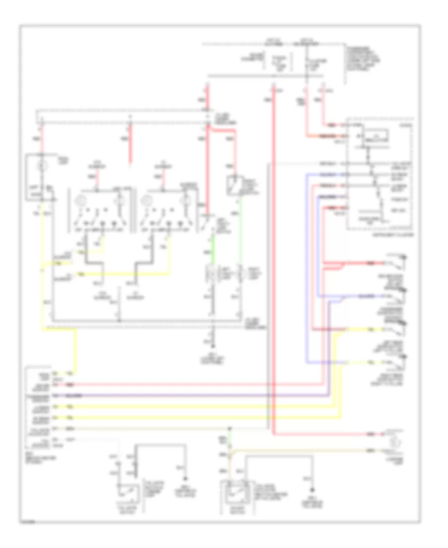
Autolamps Wiring Diagram for Hyundai Elantra Touring SE 2010
List of elements for Autolamps Wiring Diagram for Hyundai Elantra Touring SE 2010:
- Auto
- Auto light & photo sensor (top center of dash)
- Auto light ground
- Auto light power
- Auto light sensor
- Auto light signal
- Auto light sw
- B+ 1 fusible link 50a
- Bcm (behind center of dash)
- Dimmer/ passing switch
- E/r-erom
- E/r-frt
- Engine compartment relay & fuse box (in left front corner of engine compt)
- Exterior lights system
- Flash
- Fr fog fuse 10a
- Fr fog fuse 15a
- Front fog ind
- Front fog lamp relay
- Front fog lamp rly
- Front fog lamp sw
- Front fog lamp switch
- Ge11 (left front of engine compt)
- Ge24 (right front of engine compt)
- Gm21 (behind left side of dash)
- H/lp hi fuse 20a
- H/lp hi relay
- H/lp lo lh fuse 10a
- H/lp lo relay
- H/lp lo rh fuse 10a
- Head
- Head lamp fuse 15a
- Headlamp relay ctrl
- Headlamp sw
- High
- High beam ind
- High h/lp sw
- Hot at all times
- Hot in on
- I/p-c
- I/p-d
- I/p-g
- I/p-h
- Instrument cluster
- J/c jm04 (lower left side of dash)
- Left front fog lamp
- Left headlamp
- Light switch
- Low
- Low beam ind
- M01-c
- M02-l
- M04-a
- M04-c
- Multi-function switch
- Nca
- Off
- Park
- Park head
- Passenger compartment junction block (under left side of dash, near kick panel)
- Pnk
- Red
- Right front fog lamp
- Right headlamp
- Tail lamp relay
- Tail lamp relay ctrl
- Tail lamp sw input
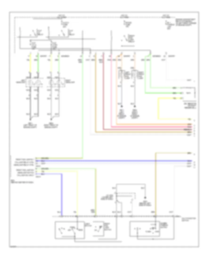
Headlights Wiring Diagram, with DRL (1 of 2) for Hyundai Elantra Touring SE 2010
List of elements for Headlights Wiring Diagram, with DRL (1 of 2) for Hyundai Elantra Touring SE 2010:
- B+ 1 fusible link 50a
- Bcm (behind center of dash)
- Dimmer/ passing switch
- Drl resistor (on right fenderwell)
- E/r-erom
- E/r-frt
- Engine compartment relay & fuse box (in left front corner of engine compt)
- Flash
- Fr fog fuse 15a
- Front fog lamp relay
- Front fog lamp rly
- Front fog lamp sw
- Front fog lamp switch
- Ge11 (left front of engine compt)
- Ge24 (right front of engine compt)
- Gm21 (behind left side of dash)
- H/lp hi fuse 20a
- H/lp hi relay
- H/lp lo lh fuse 10a
- H/lp lo relay
- H/lp lo rh fuse 10a
- Head
- Headlamp relay ctrl
- Headlamp switch
- High
- Hot at all times
- J/c jm04 (lower left side of dash)
- Left front fog lamp
- Left headlamp
- Light switch
- Low
- M02-l
- M04-a
- M04-c
- Multi-function switch
- Nca
- Off
- Park
- Pnk
- Right front fog lamp
- Right headlamp
- Taillamp relay ctrl
- Taillamp sw input
Headlights Wiring Diagram, with DRL (2 of 2) for Hyundai Elantra Touring SE 2010
List of elements for Headlights Wiring Diagram, with DRL (2 of 2) for Hyundai Elantra Touring SE 2010:
- (not used)
- Anti-lock brakes system
- Diode
- Drl control module
- Drl fuse 15a
- Fr fog fuse 10a
- Front fog ind
- Gm21 (behind left side of dash)
- H/lp lo relay
- Head- lamp fuse 15a
- High beam ind
- Hot at all times
- Hot in on
- I/p-b
- I/p-c
- I/p-d
- I/p-g
- I/p-h
- Instrument cluster
- Instrument cluster system
- Interior lights system
- J/c jm04 (lower left side of dash)
- M01-c
- Parking brake switch (on base of parking brake lever)
- Passenger compartment junction block (under left side of dash, near kick panel)
- Pnk
- Shunt connector
- Starting/ charging system
- Tail rh fuse 10a
- Tail- lamp relay
Headlights Wiring Diagram, without DRL for Hyundai Elantra Touring SE 2010
List of elements for Headlights Wiring Diagram, without DRL for Hyundai Elantra Touring SE 2010:
- B+ 1 fusible link 50a
- Bcm (behind center of dash)
- Dimmer/ passing switch
- E/r-erom
- E/r-frt
- Engine compartment relay & fuse box (in left front corner of engine compt)
- Exterior lights system
- Flash
- Fr fog fuse 10a
- Fr fog fuse 15a
- Front fog ind
- Front fog lamp relay
- Front fog lamp rly
- Front fog lamp sw
- Front fog lamp switch
- Ge11 (left front of engine compt)
- Ge24 (right front of engine compt)
- Gm21 (behind left side of dash)
- H/lp hi fuse 20a
- H/lp hi relay
- H/lp lo lh fuse 10a
- H/lp lo relay
- H/lp lo rh fuse 10a
- Head
- Head- lamp fuse 15a
- Headlamp relay ctrl
- Headlamp sw
- High
- High beam ind
- High h/lp sw
- Hot at all times
- Hot in on
- I/p-c
- I/p-d
- I/p-g
- I/p-h
- Instrument cluster
- J/c jm04 (lower left side of dash)
- Left front fog lamp
- Left headlamp
- Light switch
- Low
- Low beam ind
- M01-c
- M02-l
- M04-a
- M04-c
- Multi-function switch
- Nca
- Off
- Park
- Passenger compartment junction block (under left side of dash, near kick panel)
- Pnk
- Right front fog lamp
- Right headlamp
- Tail lamp relay ctrl
- Tail lamp sw input
- Taillamp relay
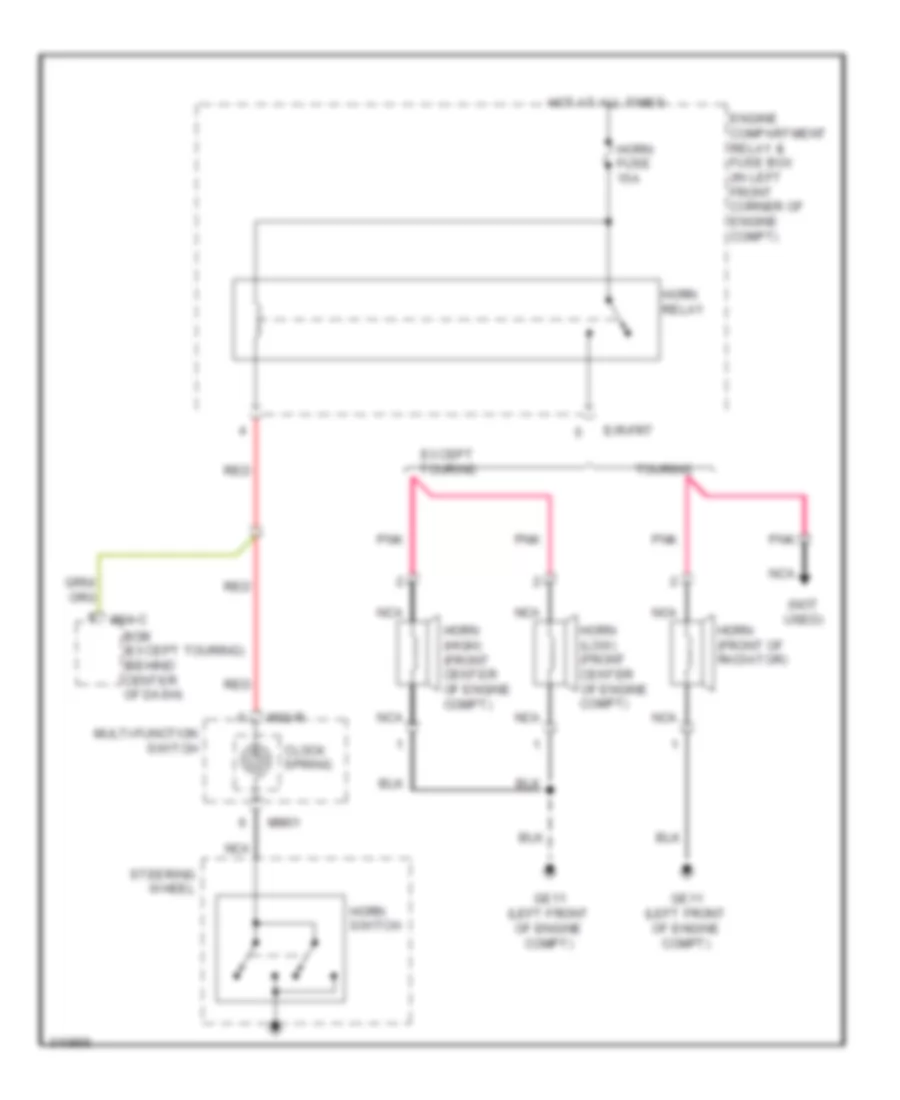
HORN
Horn Wiring Diagram for Hyundai Elantra Touring SE 2010
List of elements for Horn Wiring Diagram for Hyundai Elantra Touring SE 2010:
- (not used)
- Bcm (except touring) (behind center of dash)
- Clock spring
- E/r-frt
- Engine compartment relay & fuse box (in left front corner of engine compt)
- Except touring
- Ge11 (left front of engine compt)
- Horn (front of radiator)
- Horn (high) (front center of engine compt)
- Horn (low) (front center of engine compt)
- Horn fuse 15a
- Horn relay
- Horn switch
- Hot at all times
- M02-r
- M04-c
- Mm01
- Multi-function switch
- Nca
- Pnk
- Red
- Steering wheel
- Touring
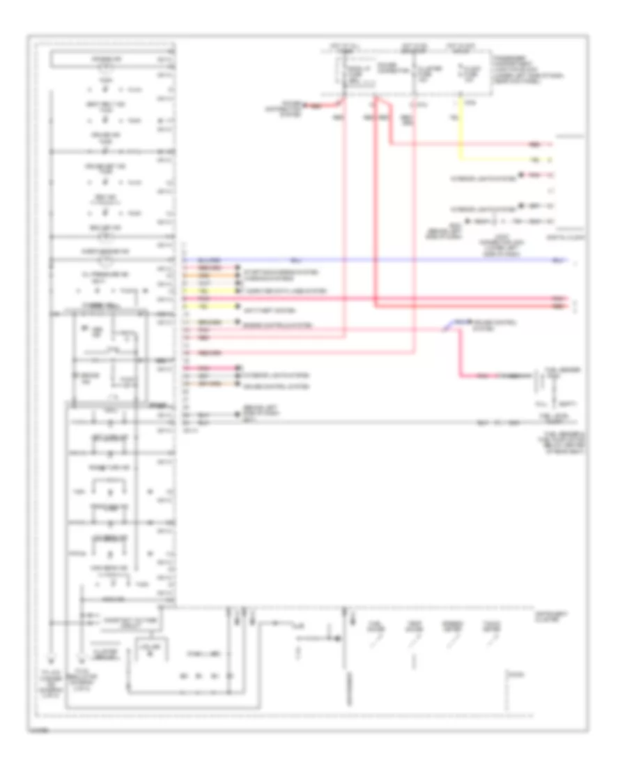
INSTRUMENT CLUSTER
Instrument Cluster Wiring Diagram (1 of 2) for Hyundai Elantra Touring SE 2010
List of elements for Instrument Cluster Wiring Diagram (1 of 2) for Hyundai Elantra Touring SE 2010:
- (behind left side of dash) gm11
- Abs
- Abs ind
- Air bag ind
- Anti-theft system
- Brake
- Brake ind
- Charge ind
- Check engine ind
- Clock fuse 10a
- Cluster fuse 10a
- Cluster ground
- Computer data lines system
- Constant voltage circuit
- Cruise control system
- Cruise ind
- Cruise set ind
- Dial ill (led)
- Digital clock
- Ebd
- Empty
- Engine controls system
- Esc ind
- Esc off ind
- Front fog ind
- Fuel gauge
- Fuel level float
- Fuel sender
- Fuel sender & fuel pump motor (below center of rear seat)
- Full
- Gm21 (behind left side of dash)
- High beam ind
- Hot at all times
- Hot in acc or on
- Hot in on or start
- I/p-b
- I/p-c
- Immo ind
- Instrument cluster
- Interior lights system
- Joint connector jm04 (lower left side of dash)
- Lcd led
- Left turn ind
- Low beam ind
- Low washer
- M01-a
- M01-c
- Micom
- Nca
- Oil pressure ind
- Passenger compartment junction block (under left side of dash, near kick panel)
- Pnk
- Power connector
- Power distribution system
- Red
- Right turn ind
- Room lp fuse 15a
- Seat belt ind
- Speedo meter
- Starting/charging system
- Tacho meter
- Temp gauge
- To 5v regulator (diagram 2 of 2)
- To low washer ind (diagram 2 of 2)
- Warning systems
Instrument Cluster Wiring Diagram (2 of 2) for Hyundai Elantra Touring SE 2010
List of elements for Instrument Cluster Wiring Diagram (2 of 2) for Hyundai Elantra Touring SE 2010:
- (in brake fluid reservoir) brake fluid level sensor
- (left rear of engine compt) esc control module
- 5v regulator
- Anti-lock brakes system
- Batt pwr
- Bcm (behind center of dash)
- Can i.c
- Cruise control system
- Diode
- Driver door switch (on left "b" pillar)
- Driver/ passenger
- Drl control module
- Drv/pass dr sw
- Eps ind
- Exterior lights system
- From constant a voltage circuit (diagram 1 of 2)
- From constant voltage circuit (diagram 1 of 2)
- Fuel gnd
- Fuel sender
- Ge23 (left rear of engine compt)
- Gm11 (behind left side of dash)
- Gm21 (behind left side of dash)
- Gnd
- Headlights system
- I/p-c
- Instrument cluster
- Joint connector jm04 (lower left side of dash)
- Left rear
- Left rear door switch (left "c" pillar)
- Low fuel ind
- Low washer ind
- Lr dr sw
- M01-a
- M01-b
- M01-c
- M04-a
- M04-b
- Micom
- Odo
- Oil pressure switch (left rear of engine)
- Parking brake switch (on base of parking brake lever)
- Passenger compartment junction block (under left side of dash, near kick panel)
- Passenger door switch (on right "b" pillar)
- Pnk
- Red
- Right rear
- Right rear door switch (right "c" pillar)
- Rr dr sw
- Speed sig
- Tail gate open
- Tail gate unlock sw
- Tpms ind
- Tpms tread ind
- Tpms(el)
- Tpms(fr)
- Tpms(rl)
- Trip range avg mpg mph
- Trip sw
- Trip switch
- Wiper/washer system
INTERIOR LIGHTS
Courtesy Lamps Wiring Diagram for Hyundai Elantra Touring SE 2010
List of elements for Courtesy Lamps Wiring Diagram for Hyundai Elantra Touring SE 2010:
- 5v regulator
- Bcm (behind center of dash)
- Cluster fuse 10a
- Door
- Door open ind
- Driver door sw
- Driver door switch (on left "b" pillar)
- Drv sw
- Gf11 (lower left kick panel)
- Gr11 (center of tail gate)
- Hot at all times
- Hot in on or start
- I/p-c
- I/p-f
- Instrument cluster
- J/c jr01 (under headliner)
- Left rear door switch (left "c" pillar)
- Left vanity lamp
- Left vanity lamp switch
- Lh rear door sw
- Lh rear dr sw
- Luggage lamp
- M01-a
- M01-b
- Map lamp
- Micom
- Nca
- Off
- Pass sw
- Passenger compartment junction block (under left side of dash, near kick panel)
- Passenger door sw
- Passenger door switch (on right "b" pillar)
- Power connector
- Red
- Rh rear door sw
- Rh rear dr sw
- Right rear door switch (right "c" pillar)
- Right vanity lamp
- Right vanity lamp switch
- Room lamp
- Room lamp m04-c
- Room lp fuse 15a
- Sunroof switch
- Tail gate actuator (bottom center of tail gate)
- Tail gate open sw
- Tail gate sw m04-b
- Tail gate switch
- Tail gate switch & license lamp
- Tail gate unlock sw
- Unlock switch
- W/ sunroof
- W/o sunroof
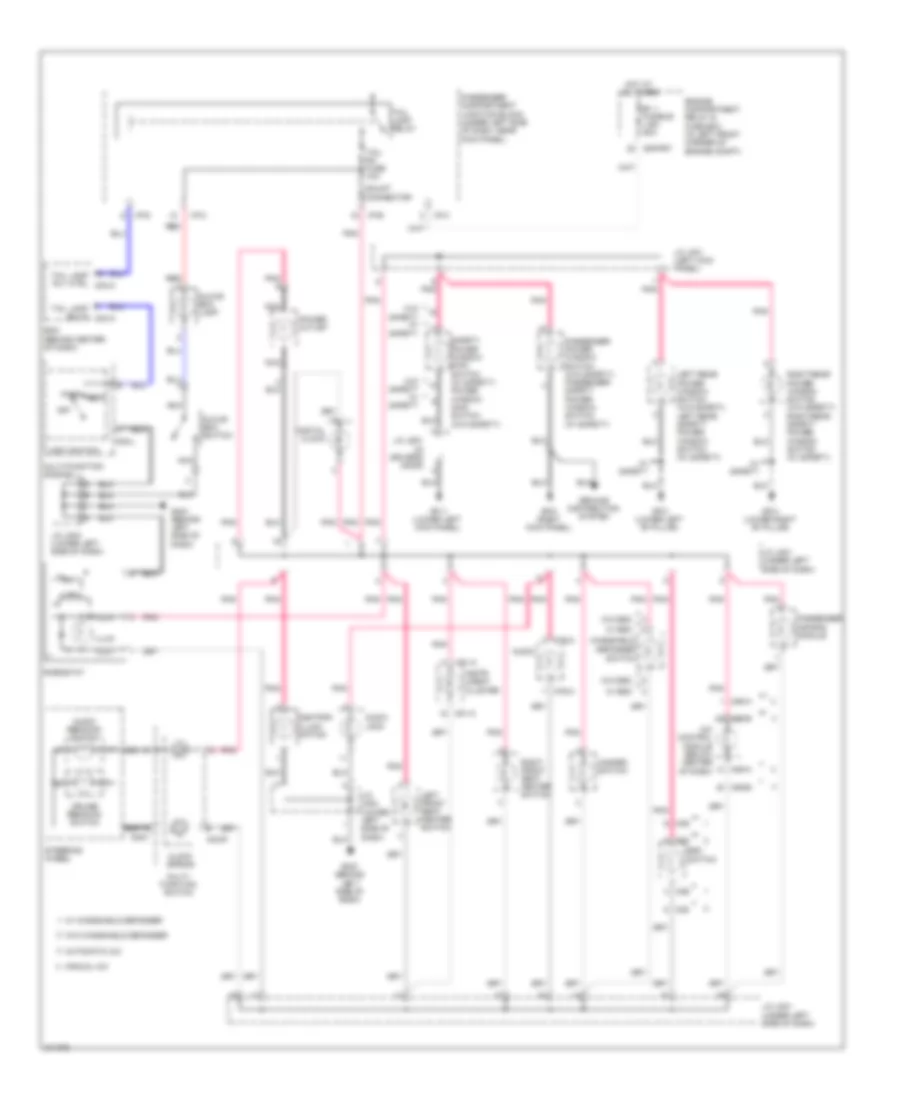
Instrument Illumination Wiring Diagram for Hyundai Elantra Touring SE 2010
List of elements for Instrument Illumination Wiring Diagram for Hyundai Elantra Touring SE 2010:
- A/c control module (below center of dash)
- Ashtray illumi- nation
- Audio
- Audio jack
- Audio remocon switch
- Automatic a/c
- B+ 1 fusible link 50a
- Bcm (behind center of dash)
- Clock spring
- Cruise remocon switch
- Defogger switch
- Digital clock
- E/r-frt
- Engine compartment relay & fuse box (in left front corner of engine compt)
- Esc switch
- Gf11 (lower left kick panel)
- Gf21 (right kick panel)
- Gf31 (lower left "b" pillar)
- Gf41 (lower right "b" pillar)
- Glove box lamp
- Glove box switch
- Gm21 (behind left side of dash)
- Ground distribution system
- Hazard switch
- Hot at all times
- I/p-b
- I/p-c
- I/p-d
- I/p-h
- Ill(+)
- Ill(-)
- Illum
- Instr- ument cluster
- J/c jd01 (in driver's door)
- J/c jf01 (left kick panel)
- J/c jm01 (under left side of dash)
- J/c jm04 (lower left side of dash)
- Left front seat heater switch
- Left rear power window switch (w/o safety) left rear safety power window switch (w/ safety)
- Light switch
- M01-a
- M02-l
- M02-r
- M05-a
- M06-b
- M22
- M36
- M76-a
- Manual a/c
- Mm01
- Multi- function switch
- Multi-function switch
- Nca
- Off
- Park head
- Passenger air bag module
- Passenger compartment junction block (under left side of dash, near kick panel)
- Passenger power window switch (w/o safety) passenger safety power window switch (w/ safety)
- Pnk
- Power outlet
- Red
- Rheostat
- Right front seat heater switch
- Right rear power window switch (w/o safety) right rear safety power window switch (w/ safety)
- Safety power window main switch (w/ safety) power window main switch (w/o safety)
- Shunt connector
- Steering wheel
- Tail lamp relay
- Tail lamp rly ctrl m04-c
- Tail lamp sw in m04-a
- Tail rh fuse 10a
- W/ esc
- W/ safety
- W/ windshield defogger
- W/o esc
- W/o safety w/ safety
- W/o windshield defogger
- Windshield
NAVIGATION
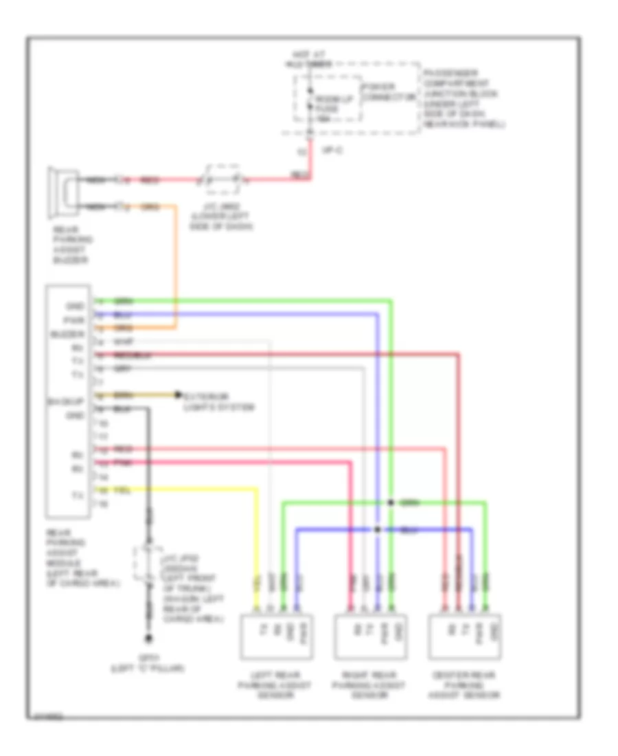
Parking Assistant Wiring Diagram for Hyundai Elantra Touring SE 2010
List of elements for Parking Assistant Wiring Diagram for Hyundai Elantra Touring SE 2010:
- Backup
- Buzzer
- Center rear parking assist sensor
- Exterior lights system
- Gf51 (left "c" pillar)
- Gnd
- Hot at all times
- I/p-c
- J/c jf02 (sedan: left front of trunk) (wagon: left rear of cargo area)
- J/c jm02 (lower left side of dash)
- Left rear parking assist sensor
- Nca
- Passenger compartment junction block (under left side of dash, near kick panel)
- Pnk
- Power connector
- Pwr
- Rear parking assist buzzer
- Rear parking assist module (left rear of cargo area)
- Red
- Right rear parking assist sensor
- Room lp fuse 15a
POWER DISTRIBUTION
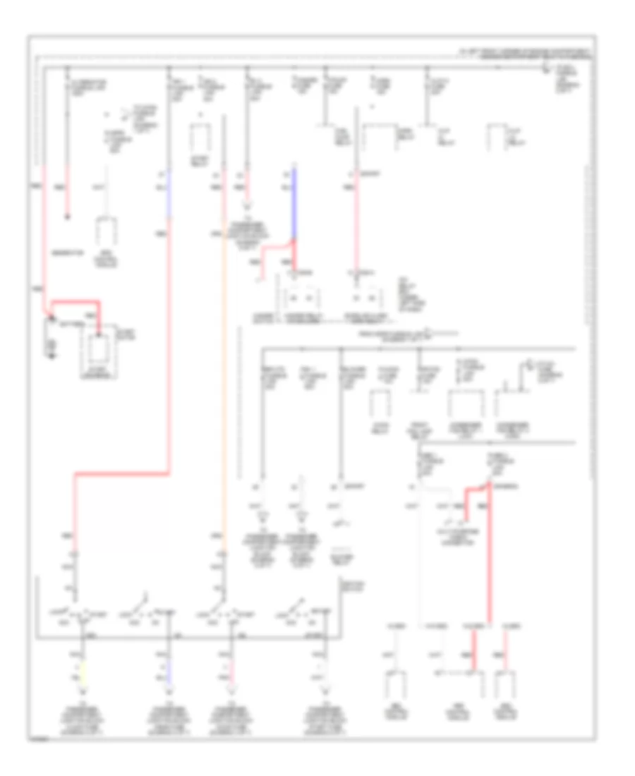
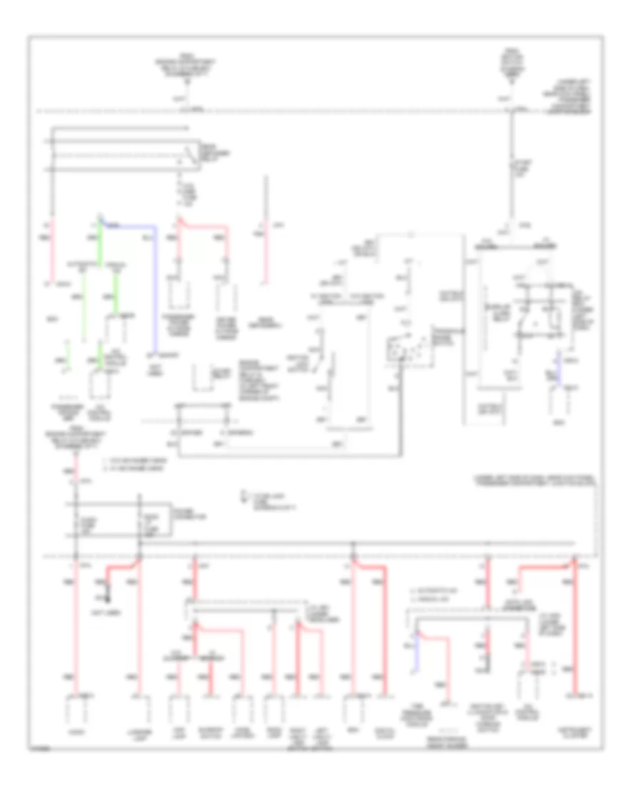
Power Distribution Wiring Diagram (1 of 7) for Hyundai Elantra Touring SE 2010
List of elements for Power Distribution Wiring Diagram (1 of 7) for Hyundai Elantra Touring SE 2010:
- (in left front corner of engine compartment) engine compartment relay & fuse box
- A/con fuse 10a
- A/con relay
- Abs 1 fusible link 40a
- Abs 2 fusible link 20a
- Abs control module
- Acc
- Alternator fusible link 150a
- B+ 1 fusible link 50a
- B+ 2 fusible link 50a
- Battery
- Blower fusible link 40a
- Blower relay
- Burglar alarm horn relay
- C/fan fusible link 40a
- Condenser fan relay 1 (low)
- Condenser fan relay 2 (high)
- E/r-erom
- E/r-frt
- Eps control module
- Esc control module
- F/pump fuse 15a
- Fr fog fuse 15a
- From mdps fusible link a (diagram 1 of 7)
- Front fog lamp relay
- Fuel pump relay
- Generator
- H/lp hi fuse 20a
- H/lp hi relay
- H/lp lo relay
- Hazard fuse 15a
- Hazard relay (w/ b/alarm)
- Hazard switch
- Horn fuse 15a
- Horn relay
- Icm relay box (under left side of dash)
- Ig1
- Ig2
- Ign 1 fusible link 30a
- Ign 2 fusible link 40a
- Ignition switch
- Lock
- M08-a
- M08-b
- Mdps fusible link 80a
- Multi-purpose check connector
- Nca
- Pnk
- Red
- Rr htd fusible link 40a
- Start
- Start motor
- Start relay
- Start solenoid
- To c/fan fusible link (diagram 1 of 7)
- To ecu fusible link (diagram 2 of 7)
- To inj fuse (diagram 2 of 7)
- To passenger compartment junction block (diagram 5 of 7)
- To passenger compartment junction block (diagram 6 of 7)
- To passenger compartment junction block a/bag fuse (diagram 2 of 7)
- To passenger compartment junction block a/con fuse (diagram 4 of 7)
- To passenger compartment junction block clock fuse (diagram 2 of 7)
- To passenger compartment junction block start fuse (diagram 5 of 7)
- W/ esc
- W/o esc
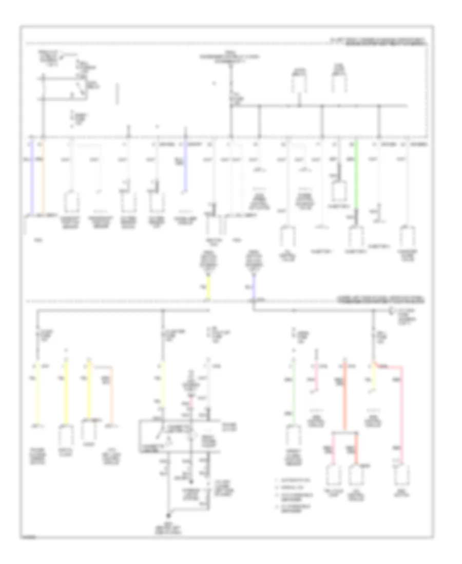
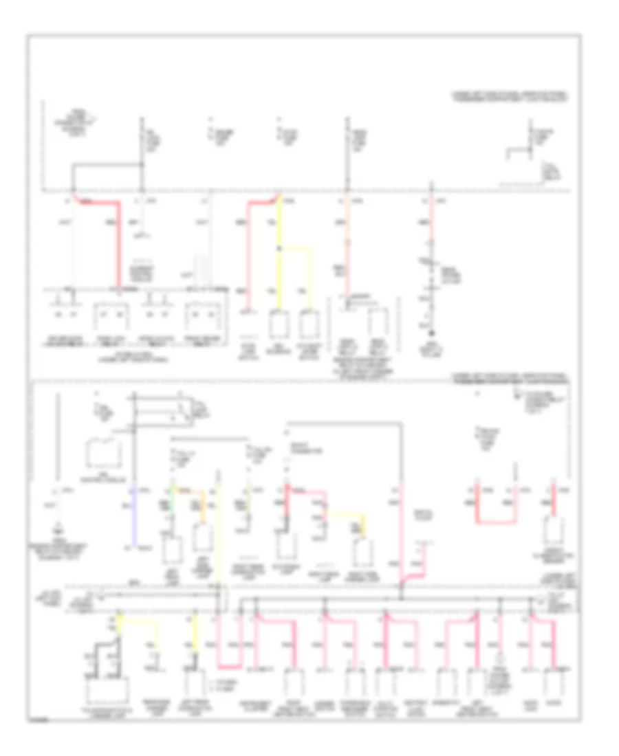
Power Distribution Wiring Diagram (2 of 7) for Hyundai Elantra Touring SE 2010
List of elements for Power Distribution Wiring Diagram (2 of 7) for Hyundai Elantra Touring SE 2010:
- (in left front corner of engine compartment) engine compartment relay & fuse box
- (under left side of dash, near kick panel) passenger compartment junction block
- A/bag fuse 15a
- A/c control module
- A/con relay
- Atm key lock control module
- Audio
- Automatic a/c
- C/lighter fuse 15a
- Camshaft position sensor
- Canister close valve
- Cbg-k
- Cigarette lighter
- Cigarette lighter ill
- Clock fuse 10a
- Crankshaft position sensor
- Digital clock
- E/r-cbg
- E/r-erom
- E/r-frt
- Ecu fusible link 30a
- Eps control module
- Esc switch
- Fr p/outlet fuse 15a
- From condenser fan relay 2 (high) (diagram 1 of 7)
- From h/lp lo relay b (diagram 1 of 7)
- From ignition switch (diagram 1 of 7)
- Front power outlet
- Fuel pump relay
- Gm21 (behind left side of dash)
- I/p-a
- I/p-b
- I/p-d
- I/p-e
- I/p-f
- Idle speed control actuator
- Ign 1 fuse 15a
- Ignition coil
- Immobilizer module
- Inj fuse 15a
- Injector 1
- Injector 2
- Injector 3
- Injector 4
- Interior lights system
- J/c jm04 (lower left side of dash)
- M06-b
- M76-a
- Main relay
- Manual a/c
- Nca
- Oil control valve
- Oxygen sensor (down)
- Oxygen sensor (up)
- Pcm
- Pnk
- Power outlet
- Power outside mirror switch
- Purge control solenoid valve
- Red
- Snsr 1 fuse 10a
- Srs control module
- Telltale lamp
- To j/c jm01 (diagram 6 of 7)
- To t/sig fuse (diagram 3 of 7)
- W/ windshield defogger
- W/o windshield defogger
- Weight classi- fication sensor
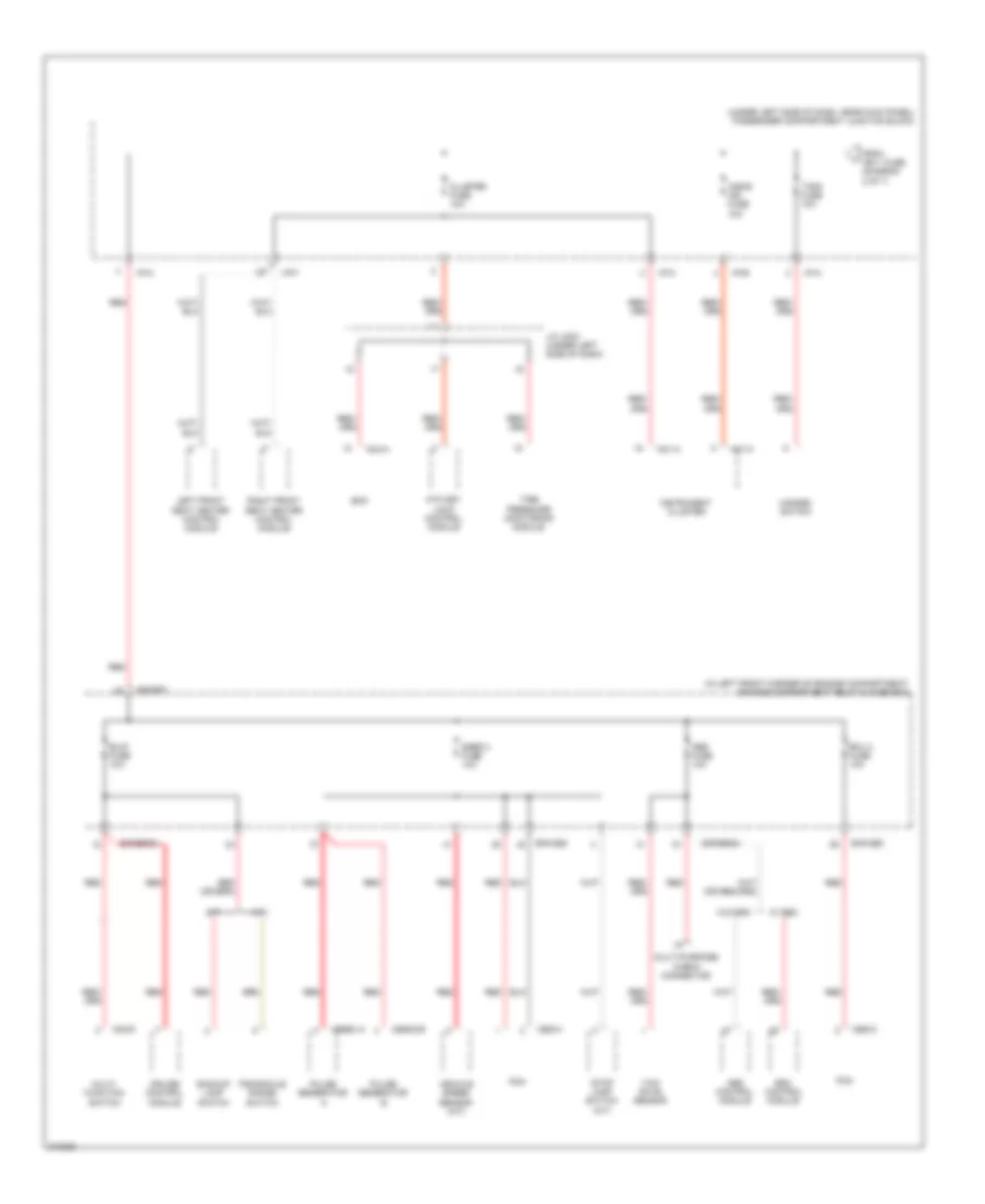
Power Distribution Wiring Diagram (3 of 7) for Hyundai Elantra Touring SE 2010
List of elements for Power Distribution Wiring Diagram (3 of 7) for Hyundai Elantra Touring SE 2010:
- (in left front corner of engine compartment) engine compartment relay & fuse box
- (under left side of dash, near kick panel) passenger compartment junction block
- A/bag ind fuse 10a
- A/t
- Abs control module
- Abs fuse 10a
- Atm key lock control module
- B/up fuse 10a
- Backup lamp switch
- Bcm
- Cbg-a
- Cbg-k
- Cbg02-a
- Cbg02-b
- Cluster fuse 10a
- Cruise control module
- E/r-cbg
- E/r-erom
- E/r-frt
- Ecu 2 fuse 10a
- Esc control module
- From ign 1 fuse (diagram 2 of 7)
- Hazard switch
- I/p-a
- I/p-b
- I/p-c
- I/p-f
- I/p-h
- Instrument cluster
- J/c jm03 (under left side of dash)
- Left front seat heater control module
- M/t
- M01-a
- M01-c
- M02-r
- M04-a
- Multi- function switch
- Multi-purpose check connector
- Pcm
- Pulse generator a
- Pulse generator b
- Red
- Right front seat heater control module
- Snsr 2 fuse 10a
- Stop lamp switch (a/t)
- T/sig fuse 10a
- Tire pressure monitoring module
- Transaxle range switch
- Vehicle speed sensor (m/t)
- W/ esc
- W/o esc
- Yaw rate sensor
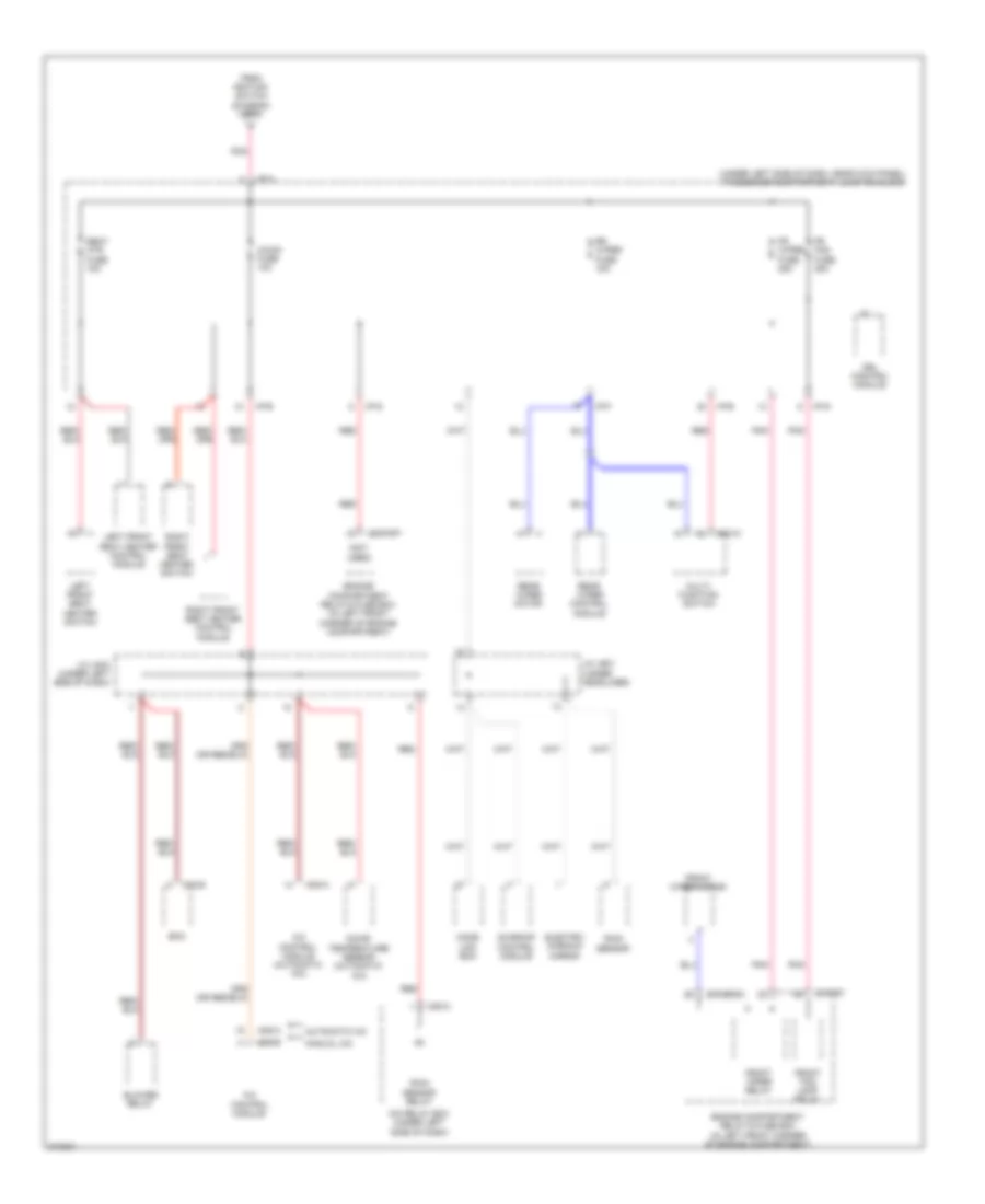
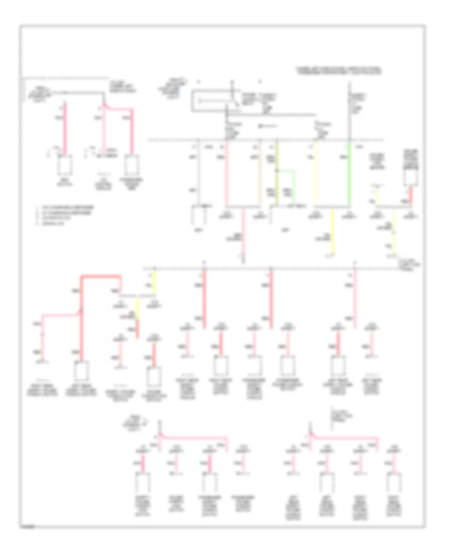
Power Distribution Wiring Diagram (4 of 7) for Hyundai Elantra Touring SE 2010
List of elements for Power Distribution Wiring Diagram (4 of 7) for Hyundai Elantra Touring SE 2010:
- (not used)
- (under left side of dash, near kick panel) passenger compartment junction block
- A/c control module
- A/c control module (automatic a/c)
- A/con fuse 10a
- Automatic a/c
- Bcm
- Blower relay
- Drl control module
- E/r-erom
- E/r-frt
- Electro- chromic mirror
- Engine compartment relay & fuse box (in left front corner of engine compartment)
- Fr fog fuse 25a
- Fr wiper fuse 25a
- From ignition switch (diagram 1 of 7)
- Front fog lamp relay
- Front wiper motor
- Front wiper relay
- Home link ecm
- I/p-a
- I/p-b
- I/p-f
- I/p-g
- Icm relay box (under left side of dash)
- Incar temperature sensor (automatic a/c)
- J/c jm03 (under left side of dash)
- J/c jr01 (under headliner)
- Left front seat heater control module
- Left front seat heater switch
- M02-w
- M04-b
- M05-a
- M06-b
- M08-a
- Manual a/c
- Multi- function switch
- Pnk
- Rain sensor
- Rain sensor relay
- Rear wiper control module
- Rear wiper motor
- Red
- Right front seat heater control module
- Right front seat heater switch
- Rr wiper fuse 15a
- Seat htr fuse 15a
- Sunroof control module
Power Distribution Wiring Diagram (5 of 7) for Hyundai Elantra Touring SE 2010
List of elements for Power Distribution Wiring Diagram (5 of 7) for Hyundai Elantra Touring SE 2010:
- (not used)
- (under left side of dash, near kick panel) passenger compartment junction block
- 87a
- A/c control module
- A/t
- Audio
- Audio fuse 15a
- Automatic a/c
- Bcm
- Burglar alarm relay
- Data link connector
- Digital clock
- Driver power outside mirror
- E/r-cbg
- E/r-erom
- E/r-frt
- Engine compartment relay & fuse box (in left front corner of engine compt)
- From engine compartment relay & fuse box (diagram 1 of 7)
- From ignition switch (diagram 1 of 7)
- Home link ecm
- Htd mirr fuse 10a
- I/p-a
- I/p-b
- I/p-c
- I/p-f
- I/p-g
- I/p-h
- Icm relay box (under left side of dash)
- Ignition key illumination & door warning switch
- Ignition lock switch
- Instrument cluster
- J/c jm02 (lower left side of dash)
- J/c jr01 (under headliner)
- Left vanity lamp switch
- Luggage lamp
- M/t
- M01-a
- M04-a
- M04-c
- M05-a
- M06-b
- M08-a
- M76-a
- Manual a/c
- Map lamp
- Nca
- Passenger air bag sbr
- Passenger power outside mirror
- Pnk
- Power connector
- Rear defogger relay
- Rear defogger(+)
- Rear parking assist buzzer
- Red
- Right vanity lamp switch
- Room lamp
- Room lp fuse 15a
- Start fuse 10a
- Start relay
- Sunroof switch
- Tire pressure monitoring module
- To dr lock fuse (diagram 6 of 7)
- Transaxle range switch l
- W/ advanced a/bag
- W/ b/alarm
- W/ ignition lock
- W/ sunroof
- W/o advanced a/bag
- W/o b/alarm
- W/o ignition lock
- W/o sunroof
Power Distribution Wiring Diagram (6 of 7) for Hyundai Elantra Touring SE 2010
List of elements for Power Distribution Wiring Diagram (6 of 7) for Hyundai Elantra Touring SE 2010:
- (diagram 5 of 7)
- (under left side of dash) j/c jm01
- (under left side of dash, near kick panel) passenger compartment junction block
- Ashtray illumi- nation
- Atm shift lever switch
- Audio
- Audio jack
- Bcm
- Deicer fuse 15a
- Digital clock
- Door lock relay
- Door unlock relay
- Dr lock fuse 20a
- Driver door unlock relay
- Drl control module
- Drl fuse 15a
- E/r-frt
- Engine compartment relay & fuse box (in left front corner of engine compt)
- From engine compartment relay & fuse box (diagram 1 of 7)
- From power connector m
- From power outlet (diagram 2 of 7)
- Front deicer relay
- Gf61 (right "c' pillar)
- Glove box lamp
- Hazard switch
- Head- lamp fuse 15a
- Head- lamp hi relay
- Head- lamp lo relay
- I/p-a
- I/p-b
- I/p-c
- I/p-d
- I/p-e
- I/p-f
- I/p-g
- I/p-h
- Icm relay box (under left side of dash)
- Instrument cluster
- J/c jf01 (left kick panel)
- Key solenoid
- Left front seat heater switch
- Left head- lamp
- Left rear combination lamp
- Left side marker lamp
- M01-a
- M02-r
- M04-c
- M08-a
- M08-b
- M76-a
- Multi- function switch
- Nca
- Pnk
- Rear power outlet
- Rear side marker lamp
- Red
- Rheostat
- Right front seat heater switch
- Right head- lamp
- Right rear combination lamp
- Right side marker lamp
- Rr fog (wcs) fuse 10a
- Shunt connector
- Stop fuse 15a
- Stop lamp switch
- Sunroof control module
- T/gate fuse 15a
- Tail gate relay
- Tail lamp relay
- Tail lh fuse 10a
- Tail rh fuse 10a
- Tailgate switch & license lamp
- To j/c jf01 (diagram 7 of 7)
- To j/c jm01 (diagram 7 of 7)
- To power window relay (diagram 7 of 7)
- W/ esc
- W/o esc
- Weight classification sensor
- Windshield defogger switch
Power Distribution Wiring Diagram (7 of 7) for Hyundai Elantra Touring SE 2010
List of elements for Power Distribution Wiring Diagram (7 of 7) for Hyundai Elantra Touring SE 2010:
- (under left side of dash, near kick panel) passenger compartment junction block
- A/c control module
- Amp
- Automatic a/c
- Bcm
- Driver safety power window module
- Esc switch
- F23-a
- From j/c jf01 q (diagram 6 of 7)
- From j/c jm01 n (diagram 6 of 7)
- From rr fog (wcs) fuse (diagram 6 of 7)
- I/p-b
- I/p-f
- J/c jf01 (left kick panel)
- J/c jm01 (under left side of dash)
- Left rear power window switch
- Left rear safety power window module
- Left rear safety power window switch
- M04-c
- M05-a
- M06-b
- Manual a/c
- P/wdw lh fuse 25a
- P/wdw rh fuse 25a
- Passenger air bag sbr
- Passenger power window switch
- Passenger safety power window module
- Passenger safety power window switch
- Pnk
- Power window main switch
- Power window relay
- Red
- Right rear power window switch
- Right rear safety power window module
- Right rear safety power window switch
- Safety p/wdw lh fuse 25a
- Safety p/wdw rh fuse 25a
- Safety power window main switch
- W/ safety
- W/ windshield defogger
- W/o safety
- W/o windshield defogger
POWER DOOR LOCKS
Power Door Locks Wiring Diagram for Hyundai Elantra Touring SE 2010
List of elements for Power Door Locks Wiring Diagram for Hyundai Elantra Touring SE 2010:
- (right front of engine compt) ge24
- 87a
- B/ alarm rly ctrl
- Bcm (behind center of dash)
- Burglar alarm horn
- Burglar alarm horn relay
- Cluster fuse 10a
- Code save
- Data link connector (below left side of dash)
- Door lock relay
- Door lock switch
- Door unlock relay
- Dr lk
- Dr lk rly ctrl
- Dr lk sw
- Dr lock fuse 20a
- Dr unlk
- Dr unlk rly ctrl
- Dr unlk sw
- Driver door lock actuator (in driver's door)
- Driver door unlock relay
- Drv dr key unlk sig
- Drv dr lk/unlk sig
- Drv dr unlk rly ctrl
- E/r-frt
- Engine compartment relay & fuse box (in left front corner of engine compt)
- Exterior lights system
- Ge24 (right front of engine compt)
- Gf11 (lower left kick panel)
- Gf21 (right kick panel)
- Gf31 (lower left "b" pillar)
- Gf41 (lower right "b" pillar)
- Gm21 (behind left side of dash)
- Ground distribution system
- Hazard rly ctrl
- Head lp sw
- Headlights system
- Hood sw
- Hood switch (front right fender)
- Horn fuse 15a
- Horn rly ctrl
- Hot at all times
- Hot in on or start
- I/p-a
- I/p-c
- Icm relay box (under left side of dash)
- Interior lights system
- J/c jd01 (in driver's door)
- J/c jm03 (under left side of dash)
- J/c jm04 (lower left side of dash)
- Key lk
- Key unlk
- Left rear door lock actuator (rear of left rear door)
- Lh rear dr unlk sig
- M04-a
- M04-b
- M04-c
- M08-a
- M08-b
- Memory power
- Nca
- On/start input
- Pass dr key lk sig
- Pass dr key unlk sig
- Pass dr lk/unlk sig
- Passenger compartment junction block (under left side of dash, near kick panel)
- Passenger door lock actuator (in front passenger door)
- Passenger safety power window switch (w/ safety) passenger power window switch (w/o safety)
- Pnk
- Power connector
- Power distribution system
- Red
- Rh rear dr unlk sig
- Right rear door lock actuator (rear of right rear door)
- Room lp fuse 15a
- Safety power window main switch (w/ safety) power window main switch (w/o safety)
- Starting/charging system
- Tail gate unlk sw
- W/ safety
- W/o safety
POWER MIRRORS
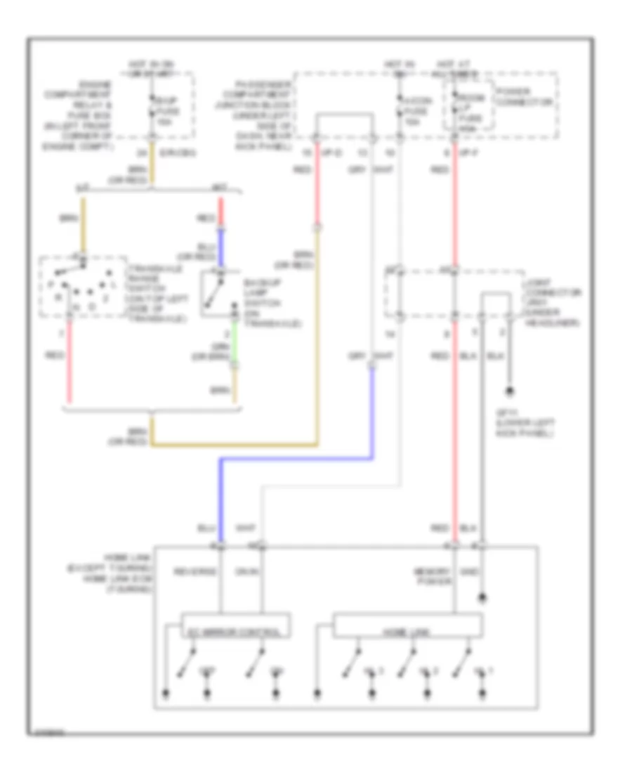
Electrochromic Mirror Wiring Diagram, with Home Link for Hyundai Elantra Touring SE 2010
List of elements for Electrochromic Mirror Wiring Diagram, with Home Link for Hyundai Elantra Touring SE 2010:
- A/con fuse 10a
- A/t
- B/up fuse 10a
- Backup lamp switch (on transaxle)
- E/r-cbg
- Ec mirror control
- Engine compartment relay & fuse box (in left front corner of engine compt)
- Gf11 (lower left kick panel)
- Gnd
- Hl 1
- Hl 2
- Hl 3
- Home link
- Home link (except touring) home link ecm (touring)
- Hot at all times
- Hot in on
- Hot in on or start
- I/p-d
- I/p-f
- Joint connector jr01 (under headliner)
- M/t
- Memory power
- Off
- On in
- Passenger compartment junction block (under left side of dash, near kick panel)
- Power connector
- Red
- Reverse
- Room lp fuse 15a
- Transaxle range switch (on top left side of transaxle)
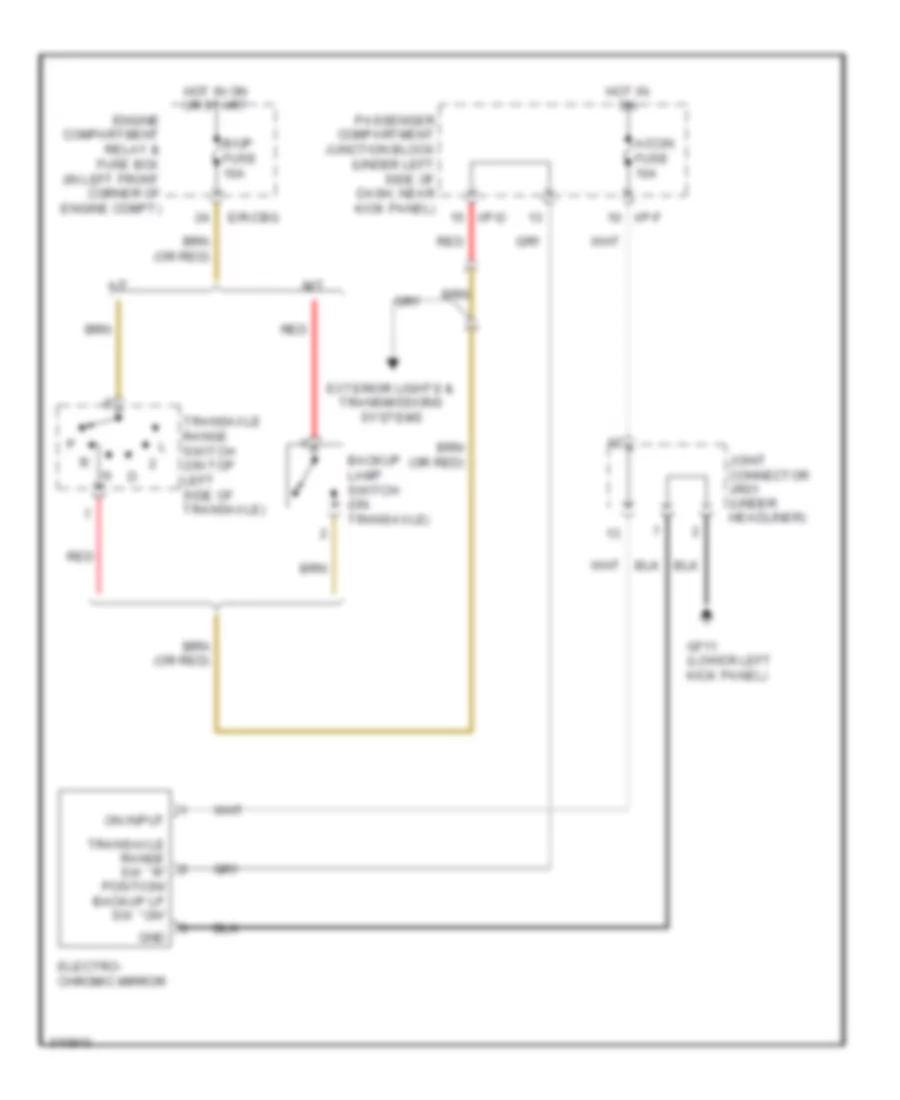
Electrochromic Mirror Wiring Diagram, without Home Link for Hyundai Elantra Touring SE 2010
List of elements for Electrochromic Mirror Wiring Diagram, without Home Link for Hyundai Elantra Touring SE 2010:
- A/con fuse 10a
- A/t
- B/up fuse 10a
- Backup lamp switch (on transaxle)
- E/r-cbg
- Electro- chromic mirror
- Engine compartment relay & fuse box (in left front corner of engine compt)
- Exterior lights & transmissions systems
- Gf11 (lower left kick panel)
- Gnd
- Hot in on
- Hot in on or start
- I/p-d
- I/p-f
- Joint connector jr01 (under headliner)
- M/t
- On input
- Passenger compartment junction block (under left side of dash, near kick panel)
- Red
- Transaxle range sw ``r" position/ backup lp sw ``on"
- Transaxle range switch (on top left side of transaxle)
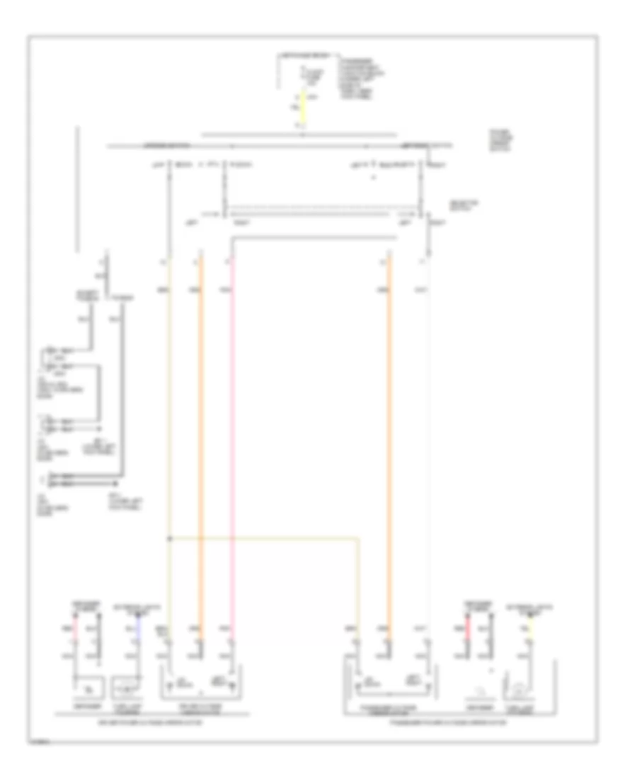
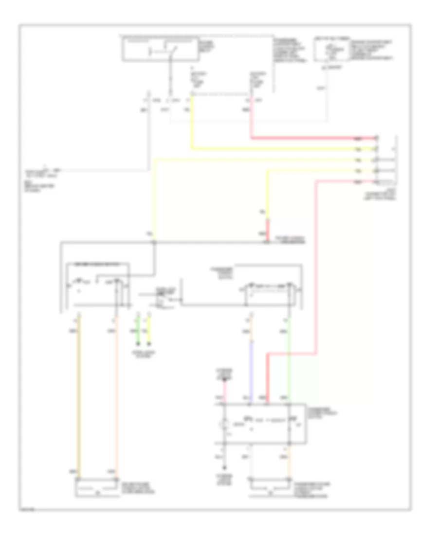
Power Mirrors Wiring Diagram for Hyundai Elantra Touring SE 2010
List of elements for Power Mirrors Wiring Diagram for Hyundai Elantra Touring SE 2010:
- Clock fuse 10a
- Defogger
- Defogger system
- Down
- Driver outside mirror motor
- Driver power outside mirror motor
- Except touring
- Exterior lights system
- Gf11 (lower left kick panel)
- Hot in acc or on
- I/p-f
- J/c jd01 (in driver's door)
- J/c jd03 & jd04 (jd04: in driver's door)
- Jd03
- Jd04
- Left
- Left/ right
- Left/right switch
- Nca
- Passenger compartment junction block (under left side of dash, near kick panel)
- Passenger outside mirror motor
- Passenger power outside mirror motor
- Pnk
- Power outside mirror switch
- Red
- Right
- Selector switch
- Touring
- Turn lamp (touring)
- Up/ down
- Up/down switch
POWER SEATS
Heated Seats Wiring Diagram for Hyundai Elantra Touring SE 2010
List of elements for Heated Seats Wiring Diagram for Hyundai Elantra Touring SE 2010:
- (lower left "b" pillar) gf31
- (right "c" pillar) gf61
- Cluster fuse 10a
- Ground
- Hi ind
- Hot in on
- Hot in on or start
- I/p-b
- I/p-f
- Ill
- Interior lights system
- Left front seat heater control module
- Left front seat heater switch
- Low ind
- On input
- On/start input
- Passenger compartment junction block (under left side of dash, near kick panel)
- Pnk
- Right front seat heater control module
- Right front seat heater switch
- Seat htr fuse 15a
- Sw signal
POWER TOP/SUNROOF
Power Top/Sunroof Wiring Diagram for Hyundai Elantra Touring SE 2010
List of elements for Power Top/Sunroof Wiring Diagram for Hyundai Elantra Touring SE 2010:
- A/con fuse 10a
- Close tilt down
- Close/ tilt dn
- Dr lock fuse 20a
- Gf11 (lower left kick panel)
- Ground
- Hot at all times
- Hot in on
- I/p-f
- J/c jr01 (under headliner)
- Memory power
- On input
- Passenger compartment junction block (under left side of dash, near kick panel)
- Slide open
- Sunroof control module
- Sunroof switch
- Tilt up
POWER WINDOWS
Power Windows Wiring Diagram, with Safety Power Windows (1 of 2) for Hyundai Elantra Touring SE 2010
List of elements for Power Windows Wiring Diagram, with Safety Power Windows (1 of 2) for Hyundai Elantra Touring SE 2010:
- (lower right "b" pillar) gf41
- Auto
- Auto down
- Auto up
- B+ 1 fusible link 50a
- Door lock switch
- Door locks system
- Down
- Driver window switch
- E/r-frt
- Ecu
- Engine compartment relay & fuse box (in left front corner of engine compartment)
- Gf11 (lower left kick panel)
- Hall effect
- Hot at all times
- I/p-f
- I/p-h
- Ill
- Interior lights system
- J/c jd01 (in driver's door)
- Left rear window switch
- Lock
- Manual
- Off
- Passenger compartment junction block (under left side of dash, near kick panel)
- Passenger window switch
- Pnk
- Protection & filter
- Red
- Relay
- Reverse
- Right rear safety power window module
- Right rear safety power window switch
- Right rear window switch
- Safety p/wdw lh fuse 25a
- Safety p/wdw rh fuse 25a
- Safety power window main switch
- Sensor
- Shunt resistor
- Sig & filter
- Sig filter
- Unlock
- Window lock switch
Power Windows Wiring Diagram, with Safety Power Windows (2 of 2) for Hyundai Elantra Touring SE 2010
List of elements for Power Windows Wiring Diagram, with Safety Power Windows (2 of 2) for Hyundai Elantra Touring SE 2010:
- (in driver's door) j/c jd01
- (lower left "b" pillar) gf31
- Auto
- Bcm (behind center of dash)
- Down
- Driver safety power window module
- Ecu
- Gf11 (lower left kick panel)
- Gf41 (lower right "b" pillar)
- Hall effect sensor
- Ill
- Interior lights system
- Joint connector jf01 (left kick panel)
- Left rear safety power window module
- Left rear safety power window switch
- Lock
- Lock sw
- M04-b
- Off
- Off up
- Passenger safety power window module
- Passenger safety power window switch
- Pnk
- Red
- Relay
- Reverse protection & filter
- Shunt resistor
- Sig & filter
- Sig filter
- Tail gate unlock sw m04-c
- Unlock
- Unlock sw
Power Windows Wiring Diagram, without Safety Power Windows with Front & Rear Power Windows for Hyundai Elantra Touring SE 2010
List of elements for Power Windows Wiring Diagram, without Safety Power Windows with Front & Rear Power Windows for Hyundai Elantra Touring SE 2010:
- (in left rear door) left rear power window motor
- Auto down con- trol unit
- B+ 1 fusible link 50a
- Bcm (behind center of dash)
- Door lock switch
- Door locks system
- Down
- Driver power window motor (in driver's door)
- Driver window switch
- E/r-frt
- Engine compartment relay & fuse box (in left front corner of engine compartment)
- Gf11 (lower left kick panel)
- Hot at all times
- I/p-b
- I/p-f
- I/p-h
- Ill
- Interior lights system
- J/c jd01 (in driver's door)
- J/c jf01 (left kick panel)
- Joint connector jf01 (left kick panel)
- Left rear power window switch
- Left rear window switch
- Lock
- M04-c
- Off
- P/wdw lh fuse 25a
- P/wdw rh fuse 25a
- Passenger compartment junction block (under left side of dash, near kick panel)
- Passenger power window motor (in front passenger door)
- Passenger power window switch
- Passenger window switch
- Pnk
- Power window main switch
- Power window relay
- Pwr wind rly ctrl
- Red
- Right rear power window motor (in right rear door)
- Right rear power window switch
- Right rear window switch
- Unlock
- Window lock switch
Power Windows Wiring Diagram, without Safety Power Windows with Front Power Windows Only for Hyundai Elantra Touring SE 2010
List of elements for Power Windows Wiring Diagram, without Safety Power Windows with Front Power Windows Only for Hyundai Elantra Touring SE 2010:
- B+ 1 fusible link 50a
- Bcm (behind center of dash)
- Door lock switch
- Door locks system
- Down
- Driver power window motor (in driver's door)
- Driver window switch
- E/r-frt
- Engine compartment relay & fuse box (in left front corner of engine compartment)
- Hot at all times
- I/p-b
- I/p-f
- I/p-h
- Ill
- Interior lights system
- Joint connector jf01 (left kick panel)
- M04-c
- Off
- Off dn
- Off up
- P/wdw lh fuse 25a
- P/wdw rh fuse 25a
- Passenger compartment junction block (under left side of dash, near kick panel)
- Passenger power window motor (in front passenger door)
- Passenger power window switch
- Passenger window switch
- Pnk
- Power window main switch
- Power window relay
- Pwr wind rly ctrl
- Red
RADIO
Radio Wiring Diagram, with Amplifier (1 of 2) for Hyundai Elantra Touring SE 2010
List of elements for Radio Wiring Diagram, with Amplifier (1 of 2) for Hyundai Elantra Touring SE 2010:
- Acc/on input
- Ambient temperature sensor 2
- Antenna (+)
- Audio
- Audio fuse 15a
- Audio jack
- Aux detect
- Aux in l
- Aux in r
- Aux l in
- Aux r in
- Aux ref
- Battery pwr
- Clock fuse 10a
- Cruise control system
- D(+) /rx
- D(+) /tx
- D(+)/rx
- D(-)/tx
- Driver door speaker
- Driver tweeter speaker
- F/cable
- Feeder cable
- Fl (+)
- Fl(-)
- Fm amp
- Fm bpf
- Fr (+)
- Fr(-)
- Gm51 (behind center of dash)
- Gnd
- Hot at all times
- Hot in acc or on
- I/p-a
- I/p-b
- Ill (+)
- Ill (-)
- Interior lights system
- Lw/mw amp
- M76-a
- M76-b
- M76-d
- M76-e
- Mute
- Nca
- Passenger compartment junction block (under left side of dash, near kick panel)
- Pnk
- Power connector
- Red
- Remocon gnd
- Remocon sig
- Remote
- Rl(+)
- Rl(-)
- Roof antenna
- Rr (+)
- Rr(-)
- Shield
- Temp
- Udb gnd
- Usb gnd
- Usb sheild
- Usb vdd
- Vdd
- Vehicle speed
Radio Wiring Diagram, with Amplifier (2 of 2) for Hyundai Elantra Touring SE 2010
List of elements for Radio Wiring Diagram, with Amplifier (2 of 2) for Hyundai Elantra Touring SE 2010:
- (+)
- (-)
- Amp (sedan: right side of trunk) (wagon: base of right "d" pillar)
- Audio remocon switch
- Battery power
- Clock spring
- Drv spk (+)
- Drv spk (-)
- F23-a
- F23-b
- Fl (+)
- Fl (-)
- Fr (+)
- Fr (-)
- Gf61 (right "c" pillar)
- Gnd
- Ground
- Hot at all times
- I/p-f
- Ill
- Interior lights system
- Left rear door speaker
- Lr spk (+)
- Lr spk (-)
- M02-r
- Mm01
- Mode
- Multi- function switch
- Mute
- Nca
- Pass spk (+)
- Pass spk (-)
- Passenger compartment junction block (under left side of dash, near kick panel)
- Passenger door speaker
- Passenger tweeter speaker
- Pnk
- Red
- Remote in
- Right rear door speaker
- Rl (+)
- Rl (-)
- Rr (+)
- Rr spk (+)
- Rr spk (-)
- Safety p/wdw rh fuse 25a
- Seek down
- Seek up
- Steering wheel
- Vol down
- Vol up
Radio Wiring Diagram, without Amplifier for Hyundai Elantra Touring SE 2010
List of elements for Radio Wiring Diagram, without Amplifier for Hyundai Elantra Touring SE 2010:
- (+)
- (-)
- Acc/on input
- Ambient temperature sensor 2
- Antenna (+)
- Audio
- Audio fuse 15a
- Audio jack
- Audio remocon switch
- Aux detect
- Aux in l
- Aux in r
- Aux l in
- Aux r in
- Aux ref
- Battery pwr
- Clock fuse 10a
- Clock spring
- Cruise control system
- D(+) /rx
- D(+) /tx
- D(+)/rx
- D(-)/tx
- Driver door speaker
- Driver tweeter speaker
- Drv spk (+)
- Drv spk (-)
- F/cable
- Feeder cable
- Fm amp
- Fm bpf
- Gm51 (behind center of dash)
- Gnd
- Hot at all times
- Hot in acc or on
- I/p-a
- I/p-b
- Ill
- Ill (+)
- Ill (-)
- Interior lights system
- Left rear door speaker
- Lr spk (+)
- Lr spk (-)
- Lw/mw amp
- M02-r
- M76-a
- M76-b
- M76-d
- M76-e
- Mm01
- Mode
- Multi- function switch
- Nca
- Pass spk (+)
- Pass spk (-)
- Passenger compartment junction block (under left side of dash, near kick panel)
- Passenger door speaker
- Passenger tweeter speaker
- Pnk
- Power connector
- Red
- Remocon gnd
- Remocon sig
- Right rear door speaker
- Roof antenna
- Rr spk (+)
- Rr spk (-)
- Seek down
- Seek up
- Shield
- Steering wheel
- Temp
- Udb gnd
- Usb gnd
- Usb shield
- Usb vdd
- Vdd
- Vehicle speed
- Vol down
- Vol up
SHIFT INTERLOCK
Shift Interlock Wiring Diagram for Hyundai Elantra Touring SE 2010
List of elements for Shift Interlock Wiring Diagram for Hyundai Elantra Touring SE 2010:
- (except touring)
- (touring)
- A/t
- Acc/on in
- Atm key lock control module (behind left center of dash)
- Atm lever switch (below center console)
- Atm sol
- Atm solenoid
- B/up fuse 10a
- Clock fuse 10a
- Cluster fuse 10a
- Cruise control module (on right fender)
- Cruise control system
- D input
- E/r-cbg
- E/r-erom
- Engine compartment relay & fuse box (in left front corner of engine compt)
- Except touring
- Gm21 (behind left side of dash)
- Ground
- Hot at all times
- Hot in acc or on
- Hot in on or start
- I/p-b
- I/p-c
- Joint connector jm03 (under left side of dash)
- Joint connector jm04 (lower left side of dash)
- Key sol
- Key solenoid (steering column)
- N input
- On/start in
- P input
- Parking position sw
- Parking position switch
- Passenger compartment junction block (under left side of dash, near kick panel)
- Pnk
- Red
- Snsr 2 fuse 10a
- Stop fuse 15a
- Stop lamp switch
- Stop lamp switch (on brake pedal bracket)
- Touring
- Transaxle range switch (on top left side of transaxle)
- Transmissions system
- Vehicle spd
STARTING/CHARGING
Charging Wiring Diagram for Hyundai Elantra Touring SE 2010
List of elements for Charging Wiring Diagram for Hyundai Elantra Touring SE 2010:
- (in left front corner of engine compt) engine compartment relay & fuse box
- (not used)
- (or red)
- Alternator fusible link 150a
- Battery
- Bcm (behind center of dash)
- Body ground
- Cbg-k
- Charge ind
- Cluster fuse 10a
- Drl control module (except touring)
- E/r-cbg
- E/r-frt
- Ecm (except touring) pcm (touring) (left rear of engine compt)
- Eng run in
- Except touring
- Generator
- Hot in on or start
- I/p junction box
- I/p-c
- I/p-d
- I/p-g
- Instrument cluster
- Joint connector jm03 (under left side of dash)
- M01-a
- M04-a
- Starting circuit
- Touring
Starting Wiring Diagram for Hyundai Elantra Touring SE 2010
List of elements for Starting Wiring Diagram for Hyundai Elantra Touring SE 2010:
- (or red)
- 87a
- A/t
- Acc
- Battery
- Bcm (behind center of dash)
- Body ground
- Burglar alarm relay
- E/r-cbg
- E/r-erom
- E/r-frt
- Engine compartment relay & fuse box (in left front corner of engine compt)
- Except touring
- Ge11 (left front of engine compt)
- I/p junction box
- I/p-a
- I/p-b
- Icm relay box (under left side of dash)
- Ign 2 fusible link 40a
- Ignition lock switch (near clutch pedal bracket)
- Ignition switch
- Lock
- M/t
- M04-c
- M08-a
- Red
- Start
- Start fuse 10a
- Start motor
- Start relay
- Start solenoid
- Touring
- Transaxle range switch (on top left side of transaxle)
- W/ b/alarm
- W/ ignition lock
- W/o b/alarm
- W/o ignition lock
SUPPLEMENTAL RESTRAINTS
Supplemental Restraints Wiring Diagram, with Advanced Air Bag (1 of 2) for Hyundai Elantra Touring SE 2010
List of elements for Supplemental Restraints Wiring Diagram, with Advanced Air Bag (1 of 2) for Hyundai Elantra Touring SE 2010:
- (lower left "b" pillar) gf31
- (lower left kick panel) gf11
- (lower right "b" pillar) gf41
- A/bag fuse 15a
- A/bag ind fuse 10a
- Air bag ind
- Computer data lines system
- Crash output
- Dab s1 high
- Dab s1 low
- Dab s2 high
- Dab s2 low
- Driver buckle
- Driver curtain air bag (upper left "c" pillar)
- Driver seat buckle switch (under driver front seat)
- Driver seat track position sensor (under driver's seat)
- Driver side air bag (under driver front seat)
- Driver side impact sensor (on left "b" pillar)
- F49
- Fis dri high
- Fis dri low
- Fis pass high
- Fis pass low
- Gm41 (behind right side of dash)
- Gnd
- Ground
- High
- Hot at all times
- Hot in on or start
- I/p-b
- I/p-d
- I/p-e
- I/p-g
- Joint connector jf01 (left kick panel)
- K-line
- Low
- M81
- Oc cla snsr
- On/start in
- Pass buckle
- Pass s1 high
- Pass s1 low
- Pass s2 high
- Pass s2 low
- Passenger compartment junction block (under left side of dash, near kick panel)
- Passenger curtain air bag (upper right "c" pillar)
- Passenger seat buckle switch (under passenger front seat)
- Passenger side air bag (under passenger front seat)
- Passenger side impact sensor (on right "b" pillar)
- Pnk
- Red
- Rr fog fuse 10a
- Seat belt warning
- Srs control module (under center console)
- Stps drive
- Telltale lamp
Supplemental Restraints Wiring Diagram, with Advanced Air Bag (2 of 2) for Hyundai Elantra Touring SE 2010
List of elements for Supplemental Restraints Wiring Diagram, with Advanced Air Bag (2 of 2) for Hyundai Elantra Touring SE 2010:
- (behind center of dash) bcm
- (below center of dash) a/c control module
- (left kick panel) joint connector jf01
- (lower left side of dash) joint connector jm04
- (under front passenger's seat) weight classification sensor
- Automatic a/c
- Clock- spring
- Crash input
- Driver air bag
- Driver air bag (in steering wheel)
- Driver seat belt pretensioner (at base of left "b" pillar)
- Gf11 (lower left kick panel)
- Gm21 (behind left side of dash)
- Gnd
- High
- Ign 1
- Instrument cluster
- Left front impact sensor (below left headlamp)
- Low
- M01-c
- M04-a
- M04-b
- M06-b
- M80
- Manual a/c
- Nca
- Os sig
- Passenger air bag (canada: behind right side of dash)
- Passenger air bag 1
- Passenger air bag 2
- Passenger seat belt pretensioner (at base of right "b" pillar)
- Pnk
- Red
- Right front impact sensor (right front of engine compt)
- Sig
- Srs ind (air bag)
- Steering wheel
- Switch seat belt
- Telltale lamp
Supplemental Restraints Wiring Diagram, with Depowered Air Bag (1 of 2) for Hyundai Elantra Touring SE 2010
List of elements for Supplemental Restraints Wiring Diagram, with Depowered Air Bag (1 of 2) for Hyundai Elantra Touring SE 2010:
- A/bag fuse 15a
- A/bag ind fuse 10a
- A01-a
- A01-b
- Air bag ind
- Computer data lines system
- Crash output
- Dab s1 high
- Dab s1 low
- Driver curtain air bag (upper left "c" pillar)
- Driver side air bag (under driver front seat)
- Driver side impact sensor (on left "b" pillar)
- Except touring
- F49
- Ga13 (except touring) (front of center console) gm41 (touring) (behind right side of dash)
- Gm41 (touring) (behind right side of dash)
- Ground
- High
- Hot in on or start
- I/p-b
- I/p-d
- I/p-e
- I/p-g
- K-line
- Low
- M81
- On/start inp
- Pass s1 low
- Pass s2 high
- Passenger compartment junction block (under left side of dash, near kick panel)
- Passenger curtain air bag (upper right "c" pillar)
- Passenger side air bag (under passenger front seat)
- Passenger side impact sensor (on right "b" pillar)
- Pnk
- Red
- Srs control module (under center console)
- Touring
Supplemental Restraints Wiring Diagram, with Depowered Air Bag (2 of 2) for Hyundai Elantra Touring SE 2010
List of elements for Supplemental Restraints Wiring Diagram, with Depowered Air Bag (2 of 2) for Hyundai Elantra Touring SE 2010:
- (except touring)
- (touring)
- A20
- Bcm (behind center of dash)
- Clock- spring
- Driver air bag
- Driver seat belt pretensioner (at base of left "b" pillar)
- Except touring
- I/p-e
- I/p-g
- Instrument cluster
- Left front impact sensor (below left headlamp)
- M01-b
- M01-c
- M04-a
- M04-b
- M80
- Multi- function switch (except touring) driver air bag (touring) (in steering wheel)
- Nca
- Passenger air bag (behind right side of dash)
- Passenger compartment junction block (under left side of dash, near kick panel)
- Passenger seat belt pretensioner (at base of right "b" pillar)
- Red
- Right front impact sensor (right front of engine compt)
- Srs ind (air bag)
- Steering wheel
- Touring
TRANSMISSION
Transmission Wiring Diagram for Hyundai Elantra Touring SE 2010
List of elements for Transmission Wiring Diagram for Hyundai Elantra Touring SE 2010:
- (not used)
- 2 input
- 2 or l sig
- 3 input
- 3 position switch
- A/t
- Anti-lock brakes system
- Atm lever switch (below center console)
- Atm solenoid valve (on top of transaxle)
- B/up fuse 10a
- Backup lamp switch
- Cbg-a
- Cruise control system
- Cruise on/off sig
- D input
- E/r-cbg
- Engine compartment relay & fuse box (in left front corner of engine compt)
- Exterior lights system
- Gbg12
- Ground
- Hot at all times
- Hot in on or start
- I/p-b
- I/p-d
- I/p-f
- Input speed sens
- L input
- Linear sol power
- Linear solenoid
- M/t
- N input
- Nca
- Od & lr pcsv-a
- Od off request
- Oil temp sens (+)
- Oil temp sens (-)
- On/off solenoid
- On/start input
- Output speed sens
- P input
- Passenger compartment junction block (under left side of dash, near kick panel)
- Pcm (left rear of engine compt)
- Pcsv-a
- Pcsv-b
- Pcsv-b 24 brake
- Pcsv-c
- Pcsv-c ud
- Pcsv-d
- Pcsv-d dccsv
- Pnk
- Pulse generator "a" (on top of transaxle)
- Pulse generator "b" (on top of transaxle)
- Pwm signal
- R input
- Red
- Sensor oil temp
- Shift interlock system
- Snsr 2 fuse 10a
- Solenoid linear
- Solenoid power
- Starting/ charging system
- Stop fuse 15a
- Stop lamp switch (on brake pedal bracket)
- Switch input
- Transaxle range switch (on top left side of transaxle)
- Veh spd output
TRUNK, TAILGATE, FUEL DOOR
Tailgate Release Wiring Diagram for Hyundai Elantra Touring SE 2010
List of elements for Tailgate Release Wiring Diagram for Hyundai Elantra Touring SE 2010:
- Bcm (body control module) (behind center of dash)
- Gr11 (center of tail gate)
- Hot at all times
- I/p-d
- I/p-f
- Instrument cluster
- M01-b
- M04-c
- Motor
- Passenger compartment junction block (under left side of dash, near kick panel)
- Ptc
- T/gate fuse 15a
- Tail gate actuator (bottom center of tail gate)
- Tail gate open
- Tail gate relay
- Tail gate rly ctrl
- Tail gate unlock sw
WARNING SYSTEMS
Chime Wiring Diagram for Hyundai Elantra Touring SE 2010
List of elements for Chime Wiring Diagram for Hyundai Elantra Touring SE 2010:
- Bcm (behind center of dash)
- Chime buzzer
- Cluster fuse 10a
- Driver door switch (on left "b" pillar)
- Driver seat belt switch (under driver front seat)
- Drv dr sw
- Gf31 (lower left "b" pillar)
- Gm21 (behind left side of dash)
- Head
- Hot at all times
- Hot in on or start
- I/p-c
- Ignition key illumination & door warning switch (right side of steering column)
- Ill
- Instrument cluster
- J/c jm02 (lower left side of dash)
- J/c jm04 (lower left side of dash)
- Key hole ill
- Key in sw
- Light switch
- M01-a
- M01-b
- M02-l
- M04-a
- M04-b
- M04-c
- Multi-function switch
- Nca
- Off
- Park
- Passenger compartment junction block (under left side of dash, near kick panel)
- Power connector
- Red
- Room lp fuse 15a
- Seat belt ind
- Seat belt sw
- Tail lmp sw in
Tire Pressure Monitoring Wiring Diagram for Hyundai Elantra Touring SE 2010
List of elements for Tire Pressure Monitoring Wiring Diagram for Hyundai Elantra Touring SE 2010:
- Batt pwr
- Can hi
- Can ic
- Can lo
- Cluster fuse 10a
- Gm21 (behind left side of dash)
- Gnd
- Hot at all times
- Hot in on or start
- I/p-c
- Instrument cluster
- J/c jm02 (lower left side of dash)
- J/c jm03 (under left side of dash)
- J/c jm04 (lower left side of dash)
- Micom
- Mo1-a
- On/start in
- Passenger compartment junction block (under left side of dash, near kick panel)
- Power connector
- Red
- Room lp fuse 15a
- Tire pressure monitoring module (behind center of dash)
- Tpms ind
- Tpms tread ind
WIPER/WASHER
Front Wiper/Washer Wiring Diagram, with Rain Sensor for Hyundai Elantra Touring SE 2010
List of elements for Front Wiper/Washer Wiring Diagram, with Rain Sensor for Hyundai Elantra Touring SE 2010:
- (right front of engine compt) ge24
- 87a
- A/con fuse 10a
- Auto
- Auto (volume)
- Bcm (behind center of dash)
- Can ic
- Cluster fuse 10a
- Computer data lines system
- Delay control
- E/r-erom
- E/r-frt
- Engine compartment relay & fuse box (in left front corner of engine compt)
- Fr wiper fuse 25a
- Front wiper motor (on left side of firewall)
- Front wiper relay
- Ge22 (left rear of engine compt)
- Ge24 (right front of engine compt)
- Gf11 (lower left kick panel)
- Ground
- Hot in on
- Hot in on or start
- I/p-b
- I/p-c
- I/p-f
- I/p-g
- Icm relay box (under left side of dash)
- Instrument cluster
- Int
- Joint connector jr01 (under headliner)
- Junction connector jm03 (under left side of dash)
- Low washer ind
- M01-a
- M01-c
- M02-w
- M08-a
- Micom
- Mist m04-b
- Mist switch
- Multi-function switch
- Off
- On input
- Parking switch
- Parking switch (shown w/ wipers at rest)
- Passenger compartment junction block (under left side of dash, near kick panel)
- Pnk
- Rain sens rly ctrl
- Rain sensor
- Rain sensor relay
- Rear wiper/ washer circuit
- Red
- Washer
- Washer level sensor (at base of reservoir)
- Washer motor
- Washer switch
- Wiper rly ctrl
- Wiper rly ctrl m04-c
- Wiper switch
Front Wiper/Washer Wiring Diagram, without Rain Sensor for Hyundai Elantra Touring SE 2010
List of elements for Front Wiper/Washer Wiring Diagram, without Rain Sensor for Hyundai Elantra Touring SE 2010:
- (right front of engine compt) ge24
- Bcm (behind center of dash)
- Can ic
- Cluster fuse 10a
- Code save
- Computer data lines system
- Delay control
- E/r-erom
- E/r-frt
- Engine compartment relay & fuse box (in left front corner of engine compt)
- Fr wiper fuse 25a
- Front wiper motor (on left side of firewall)
- Front wiper relay
- Ge22 (left rear of engine compt)
- Gm21 (behind left side of dash)
- Hot in on
- Hot in on or start
- I/p-b
- I/p-c
- I/p-g
- Instrument cluster
- Int
- Int (time)
- Joint connector jm04 (lower left side of dash)
- Low washer ind
- M01-a
- M01-c
- M02-w
- M04-b
- M04-c
- Micom
- Mist
- Mist switch
- Multi-function switch
- Off
- Parking switch (shown w/ wipers at rest)
- Passenger compartment junction block (under left side of dash, near kick panel)
- Pnk
- Rear wiper/ washer circuit
- Red
- Washer level sensor (at base of reservoir)
- Washer motor
- Washer switch
- Wiper rly ctrl
- Wiper switch
Rear Wiper/Washer Wiring Diagram for Hyundai Elantra Touring SE 2010
List of elements for Rear Wiper/Washer Wiring Diagram for Hyundai Elantra Touring SE 2010:
- Control
- Front wiper/ washer circuit
- Ge24 (right front of engine compt)
- Gf51 (left "c" pillar)
- Gr11 (center of tail gate)
- Hot in on
- Joint connector jf02 (sedan: left front of trunk) (wagon: left rear of cargo area)
- Multi-function switch
- Off
- Passenger compartment junction block (under left side of dash, near kick panel)
- Rear wiper & washer switch
- Rear wiper control module (left rear of cargo area)
- Rear wiper motor (center of tail gate)
- Rr wiper fuse 15a i/p-f
- Washer
- Washer motor
- Wiper

 Čeština
 Dansk
Dansk Deutsch
 Ελληνικά
 English
 English
 Español
 Suomi
Suomi Français
 Français
 עברית
עברית Hrvatski
 Magyar
 Italiano
 日本語
日本語 한국어
한국어 Nederlands
 Polski
 Português
 Português
 Română
 Русский
 Slovenščina
 Svenska
 Türkçe
 中文 (中国)