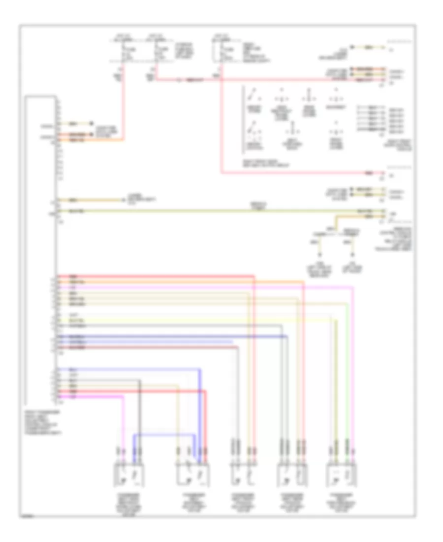
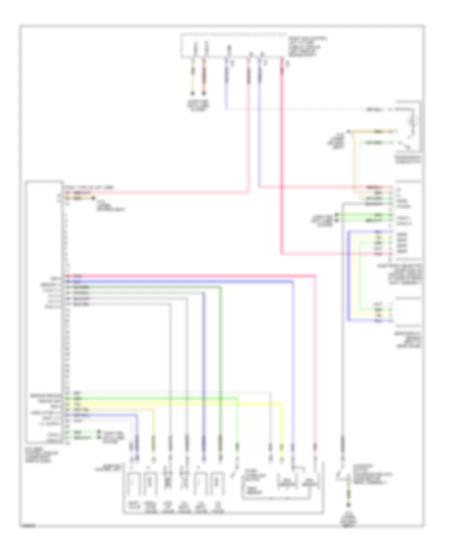
AIR CONDITIONING
Automatic A/C Wiring Diagram for Mercedes-Benz C280 2006
 https://portal-diagnostov.com/license.html
Automotive Electricians Portal FZCO
Automotive Electricians Portal FZCO
https://portal-diagnostov.com/license.html
https://portal-diagnostov.com/license.html
Automotive Electricians Portal FZCO
Automotive Electricians Portal FZCO
List of elements for Automatic A/C Wiring Diagram for Mercedes-Benz C280 2006:
- (in evaporator housing) evaporator temperature sensor
- (right rear of engine compt) w16/4
- (under left front door sill)
- (under left front door sill) w28/1
- 12v
- A/c compressor (left front of engine compt)
- Aac multifunction sensor (right rear of engine compt)
- Aac pushbutton control module
- Aac sun sensor (center rear of engine hood)
- Activated charcoal filter flap adjustment motor
- Air humidity sensor
- Blower motor
- C10
- C15
- C18
- C19
- Can h
- Can l
- Can-b h
- Can-b l
- Circuit 87 relay energized
- Circuit15r relay energized fuse 15a
- Computer data lines system
- Coolant circulation pump (w/ residual engine heat utilization system)
- Egs
- Electric suction fan engine & a/c with integrated control
- Fresh air flaps actuator
- Fresh air/recirc air flaps actuator motor
- Front pre-fuse box (at right rear of engine compt)
- Front sam control module w/ fuse & relay module (left rear of engine compt)
- Fuse 125a
- Fuse 15a
- Fuse 30a
- Heating systems recirculation unit
- Hot at all times
- In-car temperature sensor
- In-car temperature sensor fsn motor
- Instrument cluster system
- Interior fuse box (left end of dash)
- Interior lights system
- Left & right defroster flaps actuator
- Left & right footwell flaps actuator
- Left blending air flap actuator
- Left defroster vent flap actuator motor
- Left footwell flap actuator motor
- Left fresh air flap actuator
- Me-sfi control module
- Multiplex data out
- Nca
- Overhead control panel control module
- Purge control valve (left rear corner of engine compt)
- Rear blower electronic selector wheel
- Rear blower motor
- Rear blower motor control module (on rear blower motor assembly)
- Red
- Refrigerant pressure & temperature sensor (at bottom left side of radiator condensor)
- Right blending air flap actuator
- Right defroster vent flap actuator motor
- Right footwell flap actuator motor
- Right fresh air flap actuator
- W/ comfort aac
- W/ outside temperature indicator
- W16/4 (right rear of engine compt)
- W28/1
- W28/1 (under left front door sill)
- W28/1 (under left front door sill)
- W9 (behind left headlight)
ANTI-LOCK BRAKES
Anti-lock Brakes Wiring Diagram for Mercedes-Benz C280 2006
List of elements for Anti-lock Brakes Wiring Diagram for Mercedes-Benz C280 2006:
- (in left rear of engine compt) esp brake pressure sensor
- (left rear of engine compt) bas brake booster
- +5v
- Ba mv+
- Ba mv-
- Bla
- Brake fluid & parking brake warning lamp
- Brake fluid indicator switch
- Brk wear
- C10
- Can-b h
- Can-b l
- Can-c h
- Can-c l
- Computer data lines system
- Dg1+5v
- Dg1-sig
- Dg1m
- Diaphragm travel sensor
- Esp & bas control module (at left front of engine compt)
- Front axle inlet solenoid valve
- Front axle switch- over solenoid valve
- Front sam control module w/ fuse & relay module (at left rear of engine compt)
- Fuse 40a
- Fuse 50a
- Fuse 5a
- High pressure & return pump motor
- Hot at all times
- Hot w/ circuit 87 relay,chassis
- Instrument cluster
- Left front axle solenoid valve (hold)
- Left front axle solenoid valve (release)
- Left front wheel speed sensor
- Left rear axle solenoid valve (hold)
- Left rear axle solenoid valve (release)
- Left rear wheel speed sensor
- Ls1
- Ls2
- Lsr
- Mp-
- Mps
- Nca
- Rear axle inlet solenoid valve
- Rear axle switch- over solenoid valve
- Red
- Release switch
- Right front axle solenoid valve (hold)
- Right front axle solenoid valve (release)
- Right front brake pad contact sensor
- Right front wheel speed sensor
- Right rear axle solenoid valve (hold)
- Right rear axle solenoid valve (release)
- Right rear brake pad contact sensor
- Right rear wheel speed sensor
- Signal
- Solenoid valve
- Sps sol
- Sps solenoid valve (under vehicle, on
- Ss lf
- Ss lr
- Ss rf
- Ss rr
- Steering rack)
- Turn rate & lateral acceleration sensor (at front of cargo area)
- Um 1
- Um 2
- Valid for sps(pml)
- Vss lf
- Vss rf
- W16/3 (left rear of engine compt)
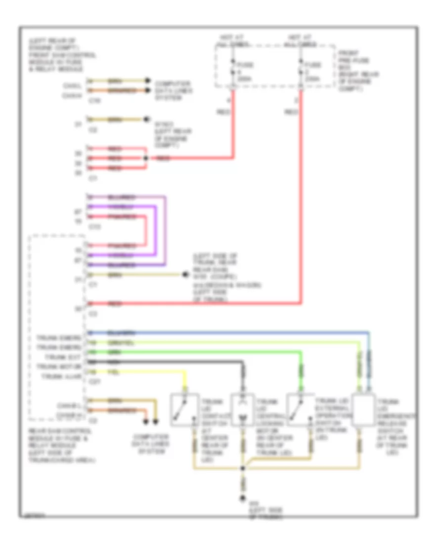
ANTI-THEFT
Anti-theft Wiring Diagram (1 of 2) for Mercedes-Benz C280 2006
List of elements for Anti-theft Wiring Diagram (1 of 2) for Mercedes-Benz C280 2006:
- (coupe)
- (coupe) (sedan)
- (sedan)
- (under left front door sill) w28/1
- Alarm signal horn
- Ata hood switch
- C10
- C13
- C14
- C21
- C22
- C23
- Can-b h
- Can-b l
- Computer data lines system
- Exterior lights system
- Front pre-fuse box (at right rear of engine compt)
- Front sam control module w/ fuse & relay module (left rear of engine compt)
- Fuse 200a
- Fuse 7.5a
- Headlights system
- Hood sw
- Hot at all times
- Left front door contact switch (at left "b" pillar)
- Left rear door contact switch (sedan, wagon) (at left "c" pillar)
- Lf door ajar
- Low beam
- Lr door ajar
- Nca
- Overhead control panel control module
- Park lamp
- Pawl
- Pawl rotary tumbler switch (center rear of tailgate)
- Pnk/red
- Rear panel cl (zv) motor
- Rear sam control module w/ fuse & relay module (left side of trunk/cargo area)
- Red
- Rf door ajar
- Right front door contact switch (at right "b" pillar)
- Right rear door contact switch (sedan, wagon) (at right "c" pillar)
- Roof drive system (coupe) (at front center of roof)
- Rr door ajar
- Screen antenna amplifier module 1 (left rear of roof)
- Screen antenna amplifier module 2
- Sedan, coupe
- Sig
- Trunk ajar
- Trunk emerg
- Trunk ext
- Trunk lid contact switch (at center rear of trunk lid)
- Trunk lid emergency release switch (sedan) (at rear of trunk lid)
- Trunk lid external operation switch (sedan) (in trunk lid)
- Trunk motor
- Turn lamp
- Turn sig
- W16/3 (left rear of engine compt)
- W16/4 (right rear of engine compt)
- W18 (under driver's seat)
- W19 (under right front door sill)
- W6 (left side of trunk)
- Wagon
Anti-theft Wiring Diagram (2 of 2) for Mercedes-Benz C280 2006
List of elements for Anti-theft Wiring Diagram (2 of 2) for Mercedes-Benz C280 2006:
- Can-b h
- Can-b l
- Can-c h
- Can-c l
- Computer data lines system
- Display
- Door motor
- Electronic ignition-starter switch (eis) control module (right side of steering column)
- Electronic steering lock control module (on steering column)
- Esa
- Fuse 30a
- Hot at all times
- Instrument cluster
- Interior central locking switch
- Interior fuse box (left end of dash)
- Ir rec
- Left front door cl motor (at rear of driver's door)
- Left front door control module (in driver's door)
- Left front ir receiver unit (at rear of left front door)
- Left rear door cl motor (at rear of left rear door)
- Left rear door control module
- Me-sfi control module (at left rear of engine compartment)
- Red
- Right front door cl motor (at rear of right front door)
- Right front door control module
- Right front ir receiver unit (at rear of right front door)
- Right rear door cl motor (at rear of right rear door)
- Right rear door control module
- Upper control panel control module
- W18 (under driver's seat)
- W19 (under right front door sill)
- W28/2
BODY CONTROL MODULES
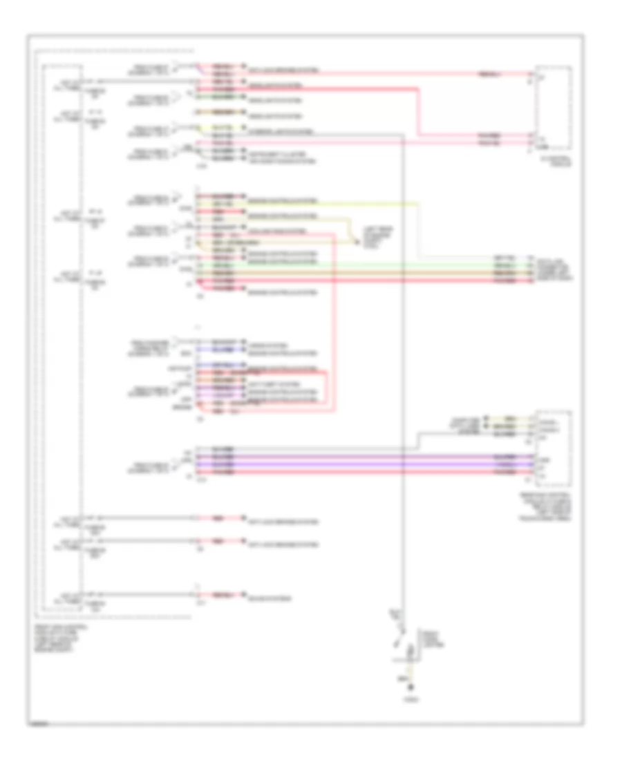
Front SAM Control Module Wiring Diagram (1 of 3) for Mercedes-Benz C280 2006
List of elements for Front SAM Control Module Wiring Diagram (1 of 3) for Mercedes-Benz C280 2006:
- 32b
- Air pump relay
- Anti-lock brakes system
- Bla
- C12
- C16
- C17
- C23
- C24
- Circuit 15r relay
- Circuit relay
- Circuit relay (chassis)
- Circuit relay (engine)
- Crash
- Diag
- Engine controls system
- Fanfare horns relay
- From fuse 45 (diagram 1 of 3)
- Front pre-fuse box (right rear of engine compt)
- Front sam control module w/ fuse & relay module (left rear of engine compt)
- Fuse
- Fuse 15a
- Fuse 200a
- Fuse 40a
- Fuse 5a
- Fuse 60a
- Fuse 7.5a
- Headlights system
- Hot at all times
- Navigation system
- Range
- Rear sam control module circuit
- Red
- Starter relay
- To pin 1, conn c19 (diagram 2 of 3)
- To pin 2, conn c2 (diagram 2 of 3)
- To pin 2, conn c3 (diagram 2 of 3)
- To pin 3, conn c13 (diagram 2 of 3)
- To pin 4, conn c12 (diagram 1 of 3)
- To pin 4, conn c19 (diagram 2 of 3)
- To pin 6, conn c19 (diagram 2 of 3)
- To pin 6, conn c2 (diagram 2 of 3)
- To pin 8, conn c19 (diagram 2 of 3)
- To pin 8, conn c3 (diagram 2 of 3)
- To pin 9, conn c2 (diagram 2 of 3)
- Transmission system
- Vss lf
- Vss rf
- Wiper
- Wiper on/off relay
- Wiper stage 1-2 relay
- Wiper/washer system
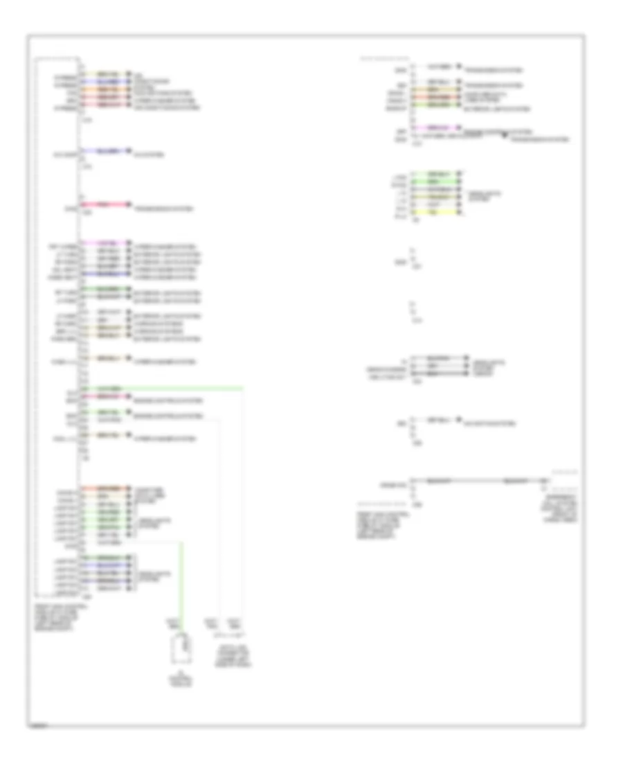
Front SAM Control Module Wiring Diagram (2 of 3) for Mercedes-Benz C280 2006
List of elements for Front SAM Control Module Wiring Diagram (2 of 3) for Mercedes-Benz C280 2006:
- (cl)
- (except cl)
- (left rear of engine compt) w16/3
- 15r
- Air conditioning system
- Air pump
- Anti-lock brakes system
- Anti-theft system
- Bridge
- C11
- C13
- C19
- Can-b h
- Can-b l
- Computer data lines system
- Cooling fans system
- Cpp
- Data link connector (under left
- Di control module
- Diag
- Ecm
- Engine controls system
- From fanfare l horns relay (diagram 1 of 3)
- From fuse 47 f (diagram 1 of 3)
- From fuse 50 i (diagram 1 of 3)
- From fuse 51 j (diagram 1 of 3)
- From fuse 51 k (diagram 1 of 3)
- From fuse 53 b (diagram 1 of 3)
- From fuse 53 c (diagram 1 of 3)
- From fuse 53 d (diagram 1 of 3)
- From fuse 54 e (diagram 1 of 3)
- From fuse 57 a (diagram 1 of 3)
- Front cigar lighter
- Front sam control module w/ fuse & relay module (left rear of engine compt)
- Fuse 57 5a
- Fuse 59 50a
- Fuse 60 40a
- Fuse 62 5a
- Fuse 63 5a
- Fuse 64 10a
- Headlights system
- Hood
- Horns system
- Hot at all times
- Instrument cluster
- Interior lights system
- Kpr
- Pnk/red
- Rear sam control module w/ fuse & relay module (left side of trunk/cargo area)
- Red
- Side of dash)
- Sound systems
- W28/2
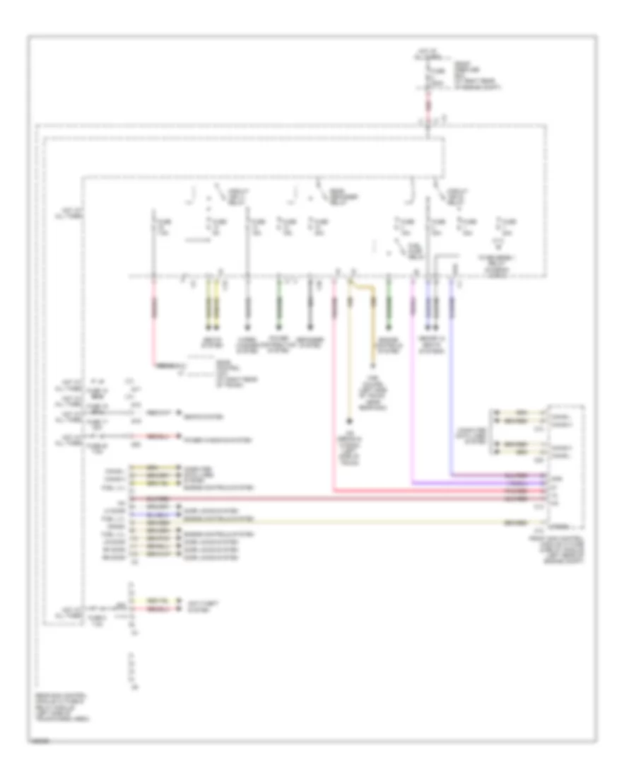
Front SAM Control Module Wiring Diagram (3 of 3) for Mercedes-Benz C280 2006
List of elements for Front SAM Control Module Wiring Diagram (3 of 3) for Mercedes-Benz C280 2006:
- 58d
- A/c comp
- A/c system
- Air conditioning system
- Air conditioning system cooling fans system
- Backup
- Brk lvl
- C10
- C14
- C15
- C18
- C20
- C21
- C22
- C24
- C25
- C26
- Can-b h
- Can-b l
- Computer data lines system
- Cool lvl
- Cpp
- Crash sig
- Data link connector (under left side of dash)
- Di control module
- Diag
- Dlc
- Ecm
- Emergency call system control unit (front of cargo area)
- Engine controls system
- Exterior lights system
- Fan
- Front sam control module w/ fuse & relay module (left rear of engine compt)
- Frt wiper
- Headlights system
- Headlights system (xenon)
- Hose heat
- L fog
- L hi
- L lo
- Lamp sw
- Lf mark
- Lf park
- Lf turn
- Navigation system
- Nzl heat
- Park brk
- Pnk
- R fog
- R hi
- R lo
- R press
- Rf mark
- Rf park
- Rf turn
- Sra
- Transmission system
- Vss lf sig out
- Warning systems
- Wash lvl
- Wiper/washer system
- Xenon diagnos
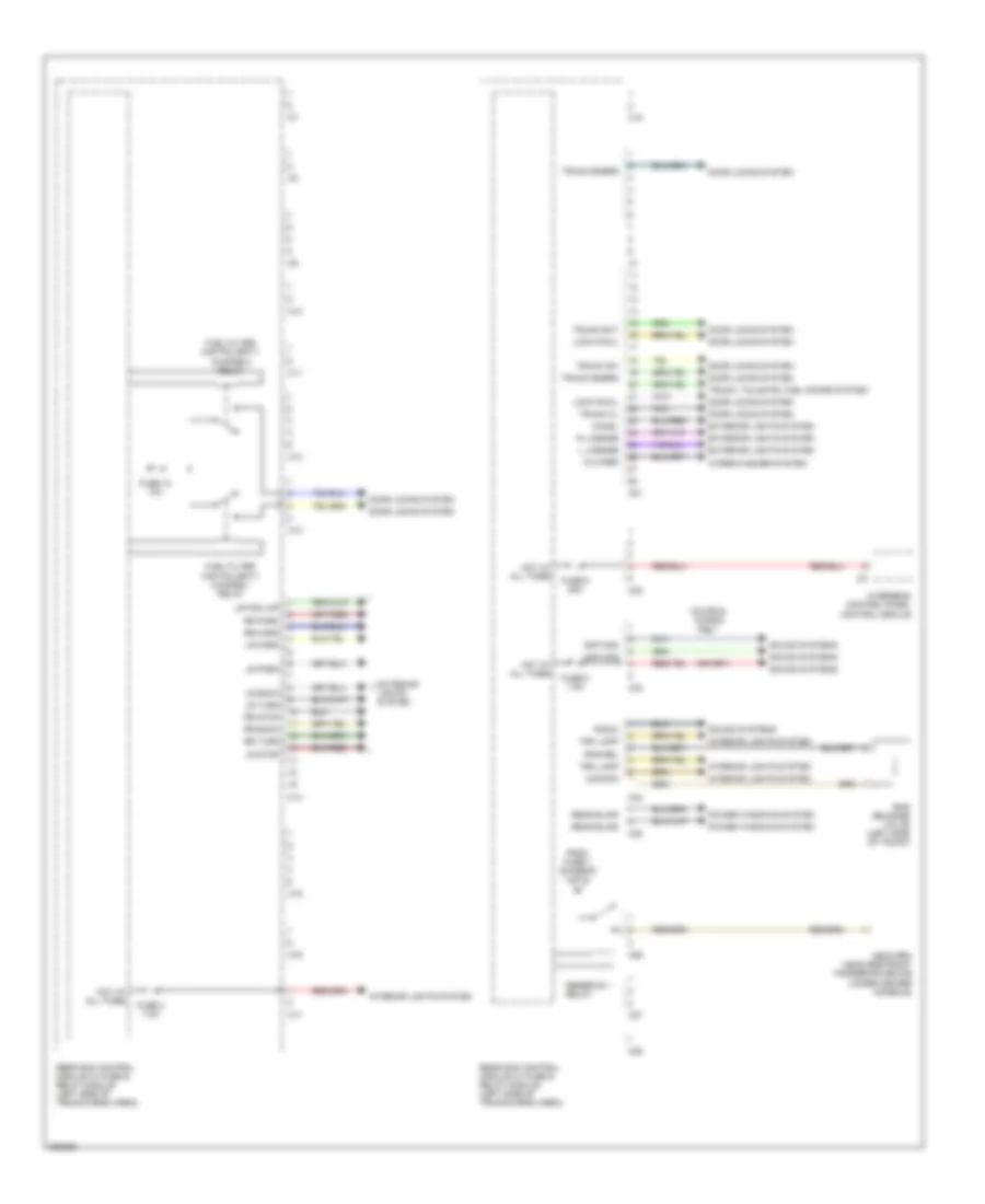
Rear SAM Control Module Wiring Diagram (1 of 2) for Mercedes-Benz C280 2006
List of elements for Rear SAM Control Module Wiring Diagram (1 of 2) for Mercedes-Benz C280 2006:
- Anti-theft system
- C10
- C12
- C13
- C19
- C20
- Can-b h
- Can-b l
- Circuit 15r (1) relay
- Circuit 15r (2) relay
- Computer data lines system
- Crash
- Defogger system
- Door locks system
- Engine controls system
- Front pre-fuse box (at right rear of engine compt)
- Front sam control module w/ fuse & relay module (left rear of engine compt)
- Fuel lvl
- Fuel pump relay
- Fuse 15a
- Fuse 17 20a
- Fuse 18 20a
- Fuse 19 20a
- Fuse 20 7.5a
- Fuse 200a
- Fuse 20a
- Fuse 30a
- Fuse 40a
- Fuse 5a
- Fuse 7.5a
- Fuse 8 7.5a
- Hot at all times
- Kpr
- Lf door
- Lr door
- Memory &
- Pnk/red
- Power distribution system
- Power windows system
- Rear defogger relay
- Rear sam control module w/ fuse & relay module (left side of trunk/cargo area)
- Red
- Rf door
- Rr door
- S17
- S18
- S19
- S20
- Sdar control unit (at right rear of trunk)
- Seats system
- Seats systems
- Sig
- To reverse 1 relay (diagram 2 of 2)
- W55 (coupe) (left side of trunk, near rear sam)
- W6 (sedan & wagon) (left side of trunk)
- Wiper/ washer system
Rear SAM Control Module Wiring Diagram (2 of 2) for Mercedes-Benz C280 2006
List of elements for Rear SAM Control Module Wiring Diagram (2 of 2) for Mercedes-Benz C280 2006:
- Amp mod
- C10
- C11
- C12
- C13
- C14
- C15
- C16
- C17
- C18
- C21
- C22
- C23
- C24
- C25
- C26
- C27
- C28
- Chmsl
- Common
- Coupe & wagon only
- Door locks system
- Exterior lights system
- From fuse 7 (diagram 1 of 2)
- Fuel filter cap polarity change 1 relay
- Fuel filter cap polarity change 2 relay
- Fuse 15 10a
- Fuse 3 7.5a
- Fuse 8 7.5a
- Fuse 9 25a
- Hot at all times
- Interior lights system
- L license
- Lock pawl
- Lr back
- Lr fog lmp
- Lr mark
- Lr park
- Lr stop
- Lr turn
- Nca
- Neck-pro head restraint triggering device (under center console)
- Overhead control panel control module
- Power windows system
- R license
- R wiper
- Radio
- Rear blind
- Rear sam control module w/ fuse & relay module (left side of trunk/cargo area)
- Reserve 1 relay
- Rhr rel
- Rhr release valve (left side of trunk)
- Rr back
- Rr mark
- Rr park
- Rr stop
- Rr turn
- Sound systems
- Trk lamp
- Trunk cl
- Trunk emerg
- Trunk ext
- Trunk sw
- Trunk, tailgate, fuel doors system
- Wiper/washer system
COMPUTER DATA LINES
Data Link Connector Wiring Diagram for Mercedes-Benz C280 2006
List of elements for Data Link Connector Wiring Diagram for Mercedes-Benz C280 2006:
- C10
- C20
- C24
- Can h
- Can l
- Computer data lines system (high/low bus circuit)
- Datalink connector (under left side of dash)
- Di control module
- Diag
- Etc control module (under right side of dash)
- Front pre-fuse box (at right rear of engine compt)
- Front sam control module w/ fuse & relay module (left rear of engine compt)
- Fuse 200a
- Fuse 5a
- Hot at all times
- Left front headlamp unit
- Me-sfi control module (at left rear of engine compt)
- Pnk/red
- Red
- Right front headlamp unit
- W16/3 (left rear of engine compt)
- W16/5 (left rear of engine compt)
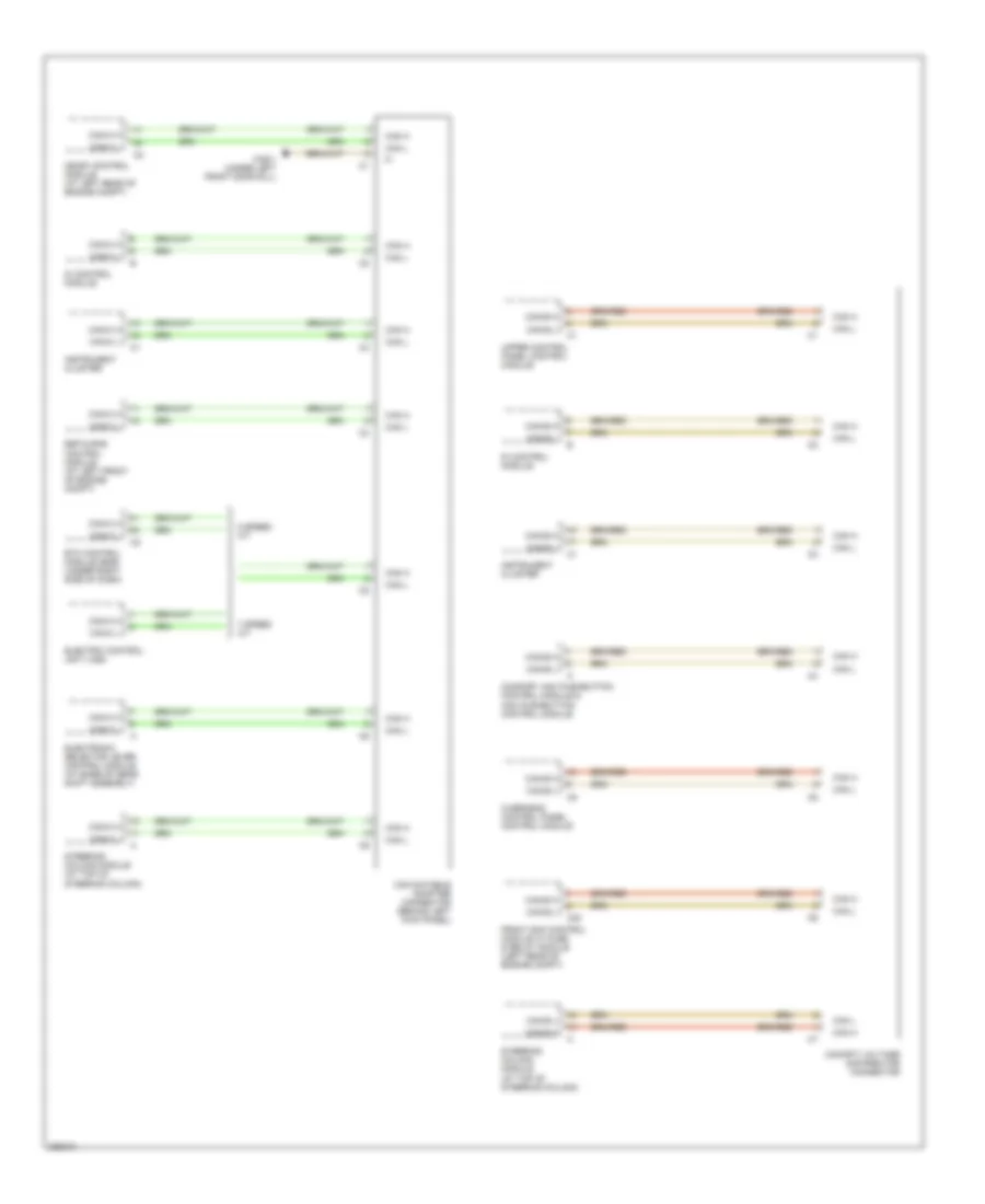
High/Low Bus Wiring Diagram (1 of 2) for Mercedes-Benz C280 2006
List of elements for High/Low Bus Wiring Diagram (1 of 2) for Mercedes-Benz C280 2006:
- 5 speed a/t
- 7 speed a/t
- C20
- Can databus adapter connector (behind left kick panel)
- Can h
- Can l
- Can-b h
- Can-b l
- Can-c h
- Can-c l
- Cockpit voltage distributor connector
- Comfort aac pushbutton control module & aac pushbutton control module
- Di control module
- Electric control unit (vgs)
- Electronic selector lever control module (at base of gear shift assembly)
- Esp & bas control module (at left front of engine compt)
- Etc control module (egs) (under right side of dash)
- Front sam control module w/ fuse & relay module (left rear of engine compt)
- Instrument cluster
- Me-sfi control module (at left rear of engine compt)
- Overhead control panel control module
- Steering column module (at top of steering column)
- Upper control panel control module
- W28/1 (under left front door sill)
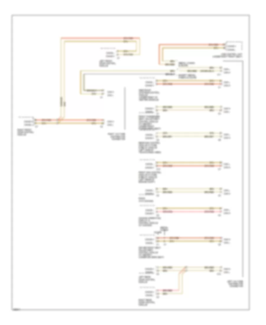
High/Low Bus Wiring Diagram (2 of 2) for Mercedes-Benz C280 2006
List of elements for High/Low Bus Wiring Diagram (2 of 2) for Mercedes-Benz C280 2006:
- C10
- C11
- Can h
- Can l
- Can-b h
- Can-b l
- Comand operating, display & control module (w/ comand)
- Coupe
- Driver front seat adjustment control module (w/ memory) (under driver's seat)
- Except sedan, wagon & coupe
- Front passenger seat adjustment control module (w/ memory) (under front passenger's seat)
- Front sam control module w/ fuse & relay module (left rear of engine compt)
- Left front door control module
- Left rear door control module
- Left voltage distributor connector
- Radio (w/o comand)
- Rear sam control module w/ fuse & relay module (left side of trunk/cargo area)
- Restraint systems control module (under front of center console)
- Right front door control module
- Right rear door control module
- Right voltage distributor connector
- Sedan, wagon
- Sedan, wagon & coupe
- Wss control unit (under right front seat)
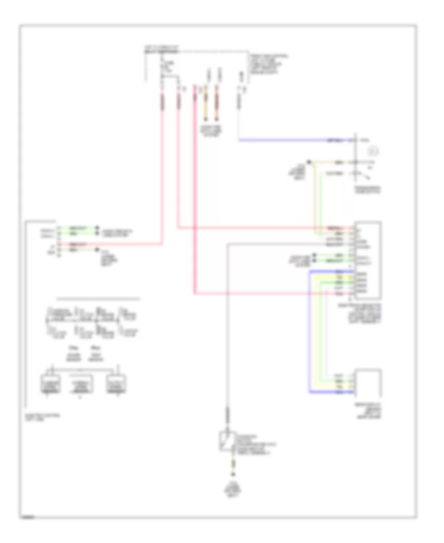
COOLING FAN
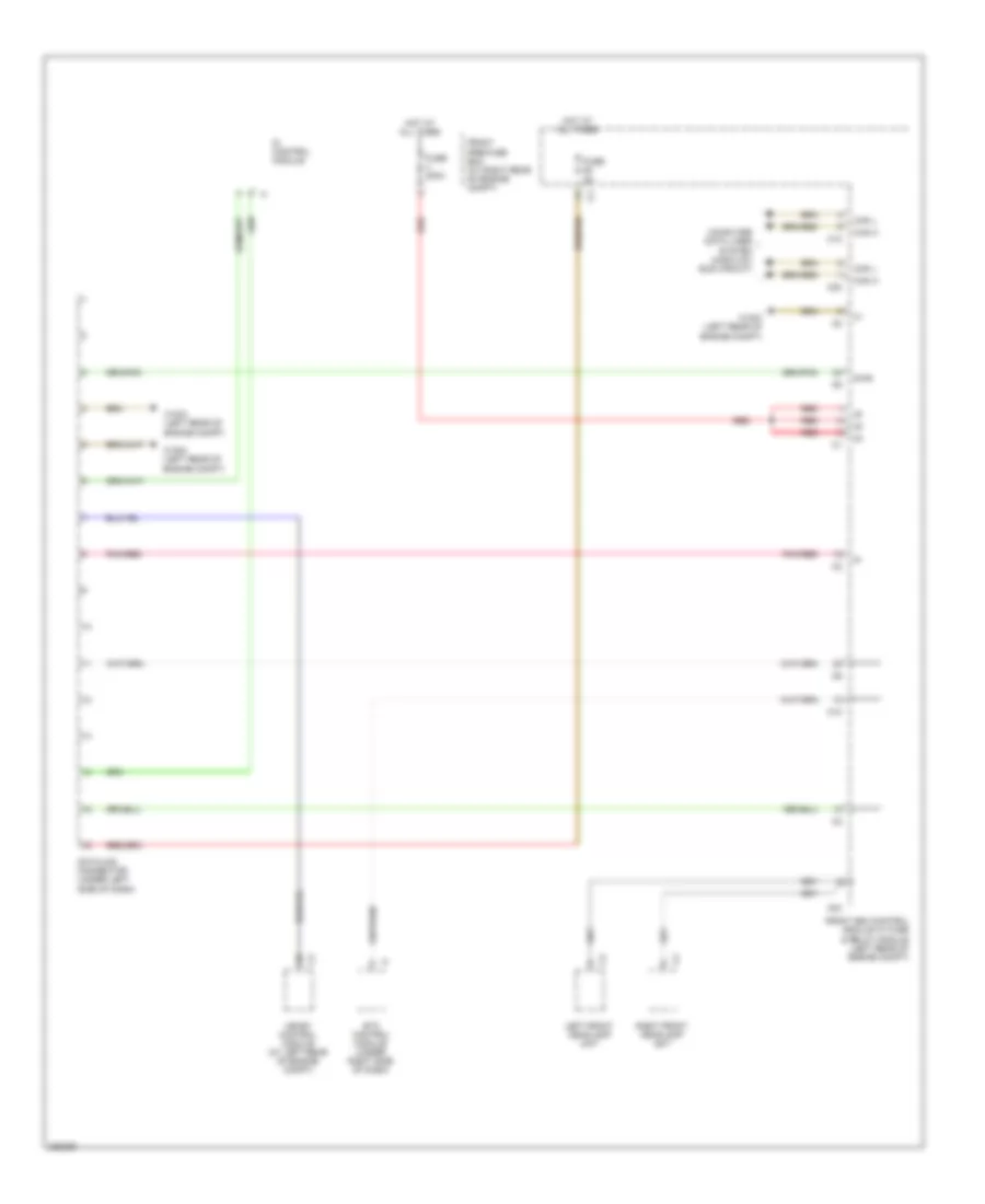
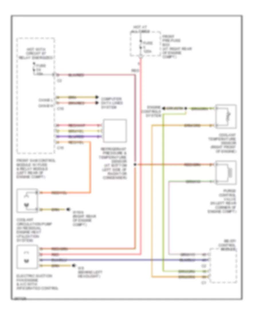
Cooling Fan Wiring Diagram for Mercedes-Benz C280 2006
List of elements for Cooling Fan Wiring Diagram for Mercedes-Benz C280 2006:
- C10
- C15
- Can-b h
- Can-b l
- Computer data lines system
- Coolant circulation pump (w/ residual engine heat utilization system)
- Coolant temperature sensor (right front of engine)
- Electric suction fan engine & a/c with integrated control
- Engine controls system
- Front pre-fuse box (at right rear of engine compt)
- Front sam control module w/ fuse & relay module (left rear of engine compt)
- Fuse 125a
- Fuse 15a
- Hot at all times
- Hot with circuit 87 relay energized
- Me-sfi control module
- Purge control valve (in left rear corner of engine compt)
- Red
- Refrigerant pressure & temperature sensor (at bottom left side of radiator condenser)
- W16/4 (right rear of engine compt)
- W9 (behind left headlight)
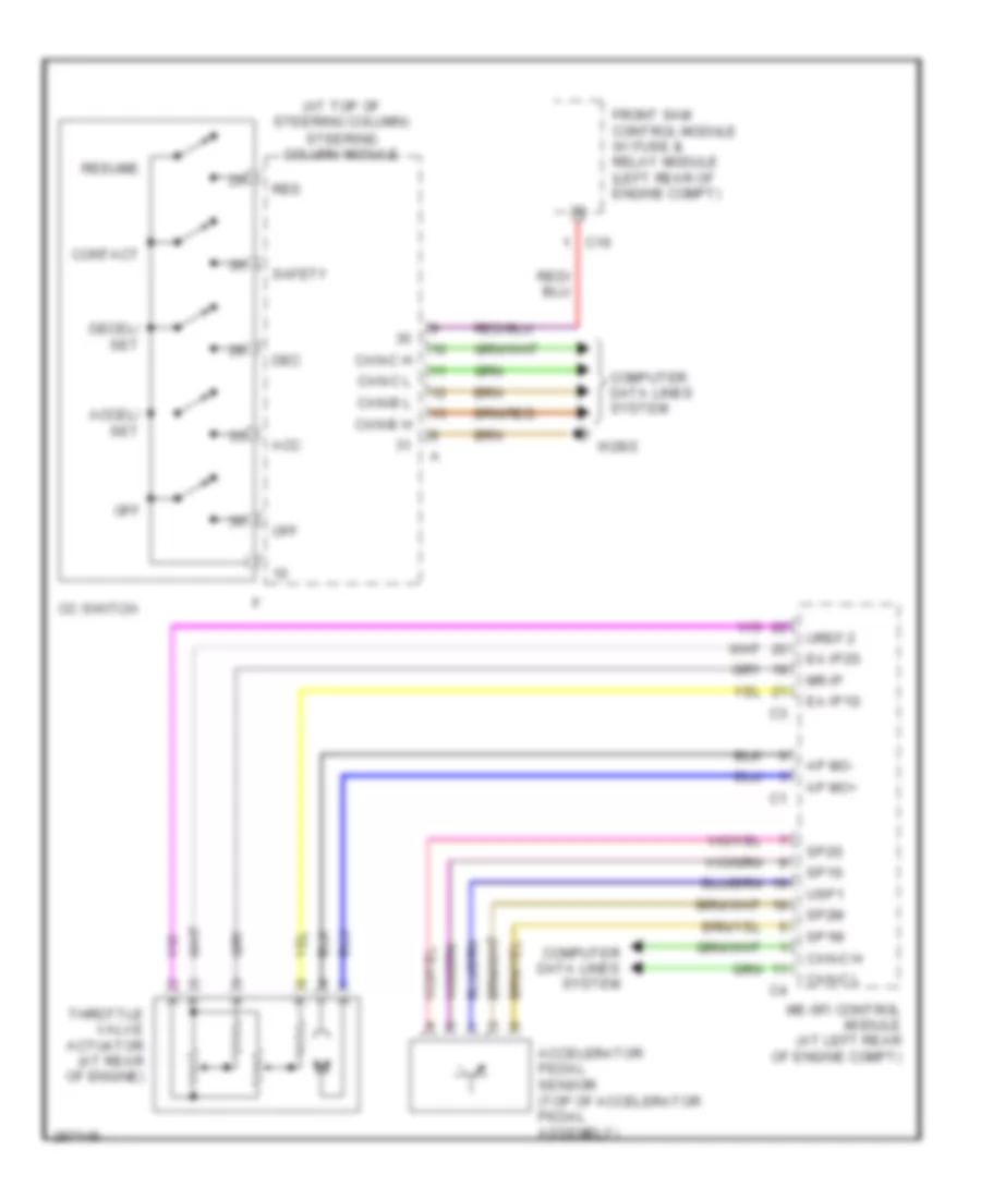
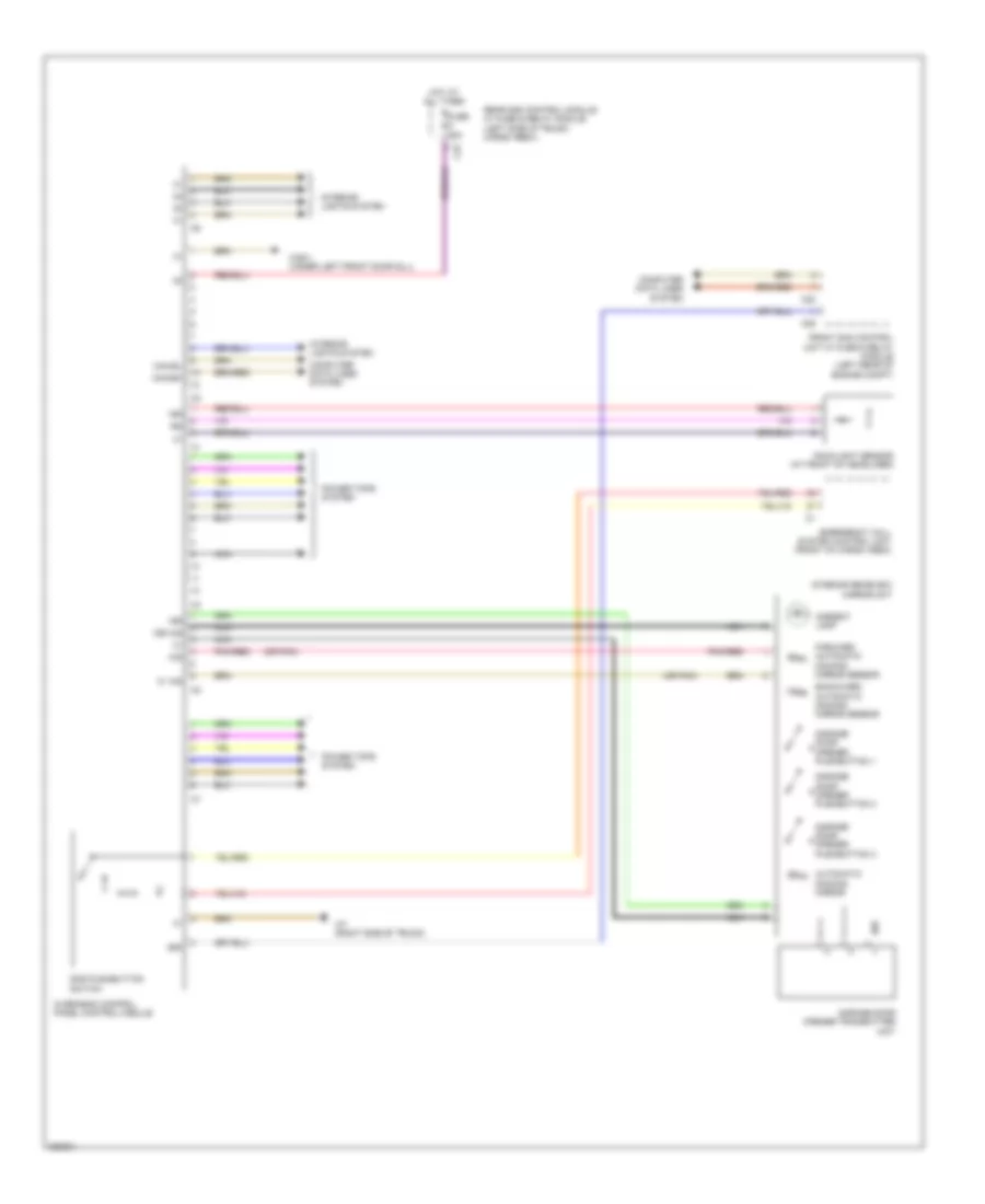
CRUISE CONTROL
Cruise Control Wiring Diagram for Mercedes-Benz C280 2006
List of elements for Cruise Control Wiring Diagram for Mercedes-Benz C280 2006:
- (at top of steering column) steering column module
- Acc
- Accel/ set
- Accelerator pedal sensor (top of accelerator pedal assembly)
- Ap mo+
- Ap mo-
- C19
- Can-b h
- Can-b l
- Can-c h
- Can-c l
- Cc switch
- Computer data lines system
- Contact
- Dec
- Decel/ set
- Ea ip1s
- Ea ip2s
- Front sam control module w/ fuse & relay module (left rear of engine compt)
- Me-sfi control module (at left rear of engine compt)
- Mr ip
- Off
- Res
- Resume
- Safety
- Sp1m
- Sp1s
- Sp2m
- Sp2s
- Throttle valve actuator (at rear of engine)
- Uref 2
- Usp1
- W28/2
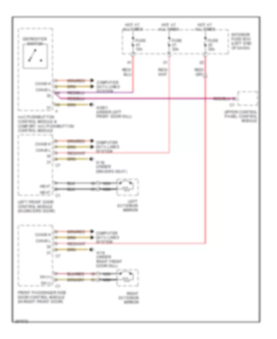
DEFOGGERS
Heated Mirrors Wiring Diagram for Mercedes-Benz C280 2006
List of elements for Heated Mirrors Wiring Diagram for Mercedes-Benz C280 2006:
- Aac pushbutton control module & comfort aac pushbutton control module
- Can-b h
- Can-b l
- Computer data lines system
- Defroster switch
- Driver's seat)
- Front passenger side door control module (in right front door)
- Fuse 15a
- Fuse 30a
- Heat
- Hot at all times
- Interior fuse box (left end of dash)
- Left exterior mirror
- Left front door control module (in driver's door)
- Nca
- Right exterior mirror
- Sh (+)
- Sh (-)
- Upper control panel control module
- W18 (under
- W19 (under right front door sill)
- W28/1 (under left front door sill)
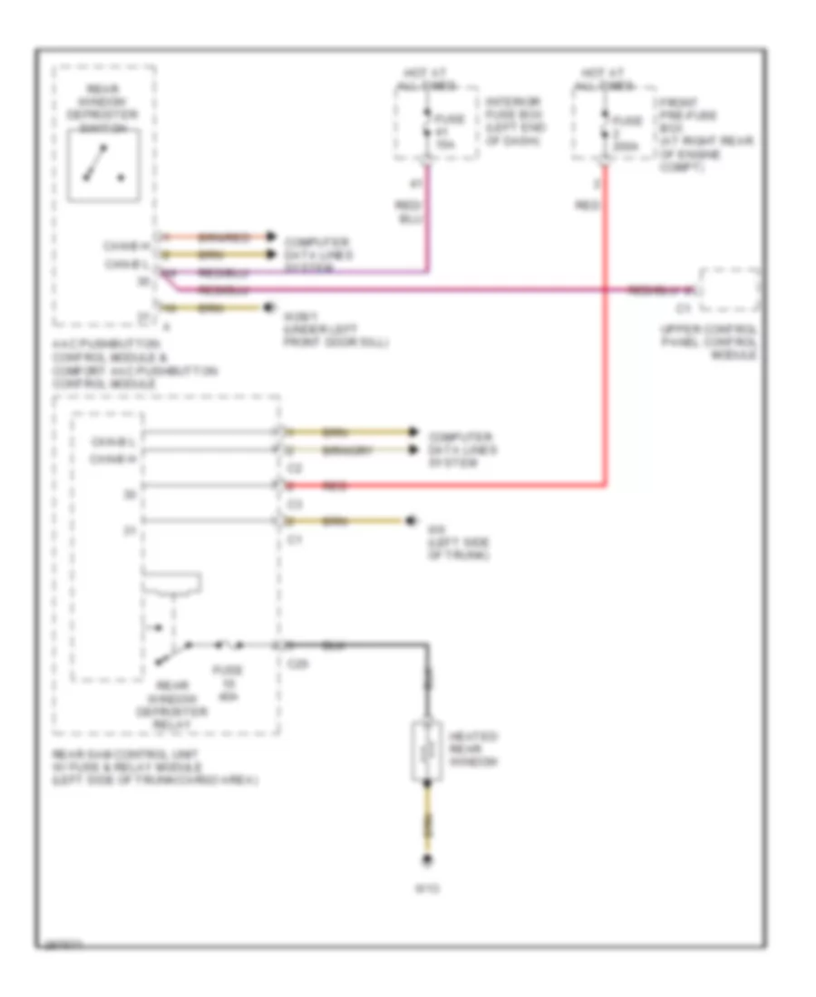
Rear Defogger Wiring Diagram for Mercedes-Benz C280 2006
List of elements for Rear Defogger Wiring Diagram for Mercedes-Benz C280 2006:
- Aac pushbutton control module & comfort aac pushbutton control module
- C20
- Can-b h
- Can-b l
- Computer data lines system
- Front pre-fuse box (at right rear of engine compt)
- Fuse 15a
- Fuse 200a
- Fuse 40a
- Heated rear window
- Hot at all times
- Interior fuse box (left end of dash)
- Rear sam control unit w/ fuse & relay module (left side of trunk/cargo area)
- Rear window defroster relay
- Rear window defroster switch
- Red
- Upper control panel control module
- W13
- W28/1 (under left front door sill)
- W6 (left side of trunk)
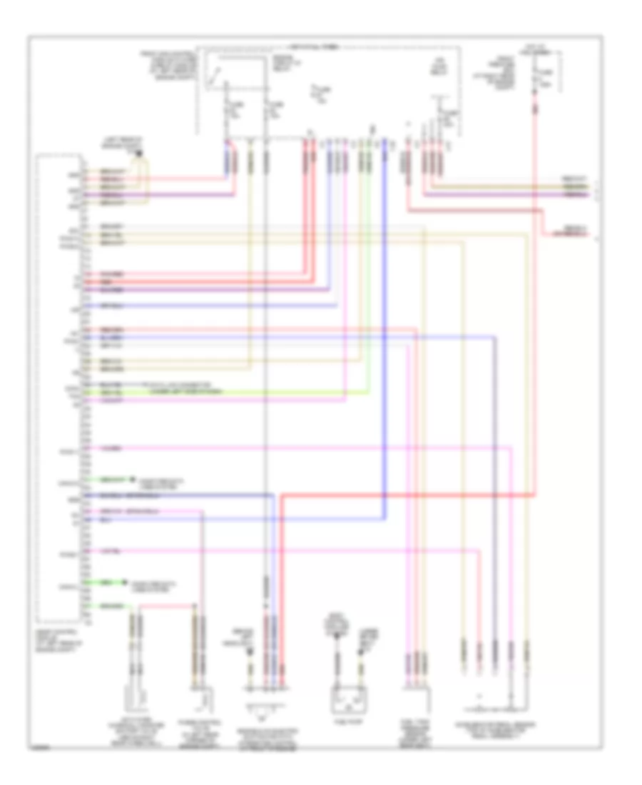
ENGINE PERFORMANCE
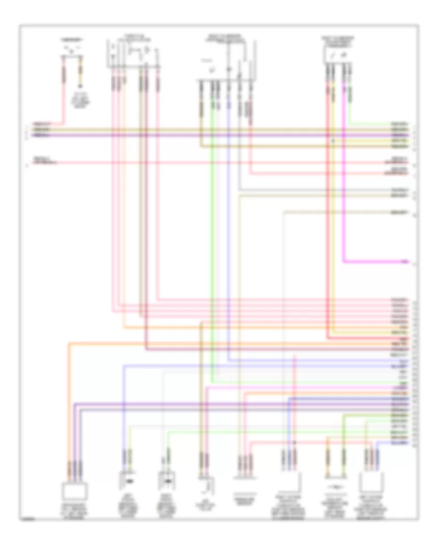
3.0L
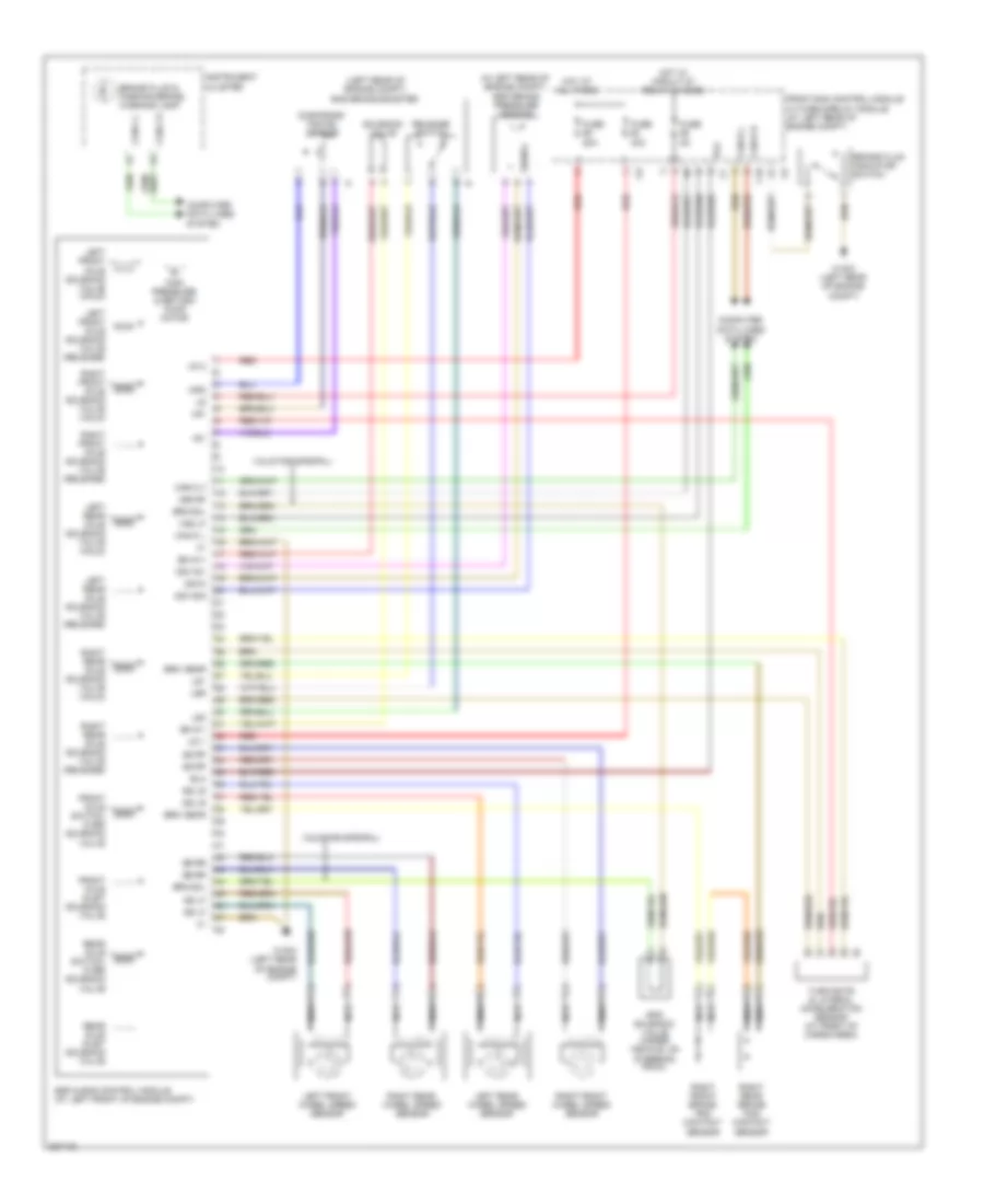
3.0L, Engine Performance Wiring Diagram (1 of 4) for Mercedes-Benz C280 2006
List of elements for 3.0L, Engine Performance Wiring Diagram (1 of 4) for Mercedes-Benz C280 2006:
- (-)
- (behind left headlight) w9
- (left rear of engine compt) w16/5
- (under driver seat) w18
- +5v
- Accelerator pedal sensor (top of accelerator pedal assembly)
- Activated charcoal canister shutoff valve (above right rear wheelwell)
- Air
- Air pump relay
- Body control modules system
- C17
- C18
- Can-c-h
- Can-c-l
- Computer data lines system
- Data link connector (under left side of dash)
- Diag.
- Egs
- Engine & a/c electric suction fan with integrated control (at front of engine)
- Engine circuit 87 relay,
- Front pre-fuse box (at right rear of engine compt)
- Front sam control module w/ fuse & relay module (at left rear of engine compt)
- Fuel pump
- Fuel tank pressure sensor (under left rear seat)
- Fuse 125a
- Fuse 15a
- Fuse 40a
- Gnd
- Hot at all times
- Me-sfi control module (at left rear of engine compt)
- Nca
- Pnk/red
- Purge control valve (in left rear corner of engine compt)
- Pwg+
- Pwg1-0
- Pwg1-1
- Pwg2-0
- Pwg2-1
- Red
- Sig.
- Tna
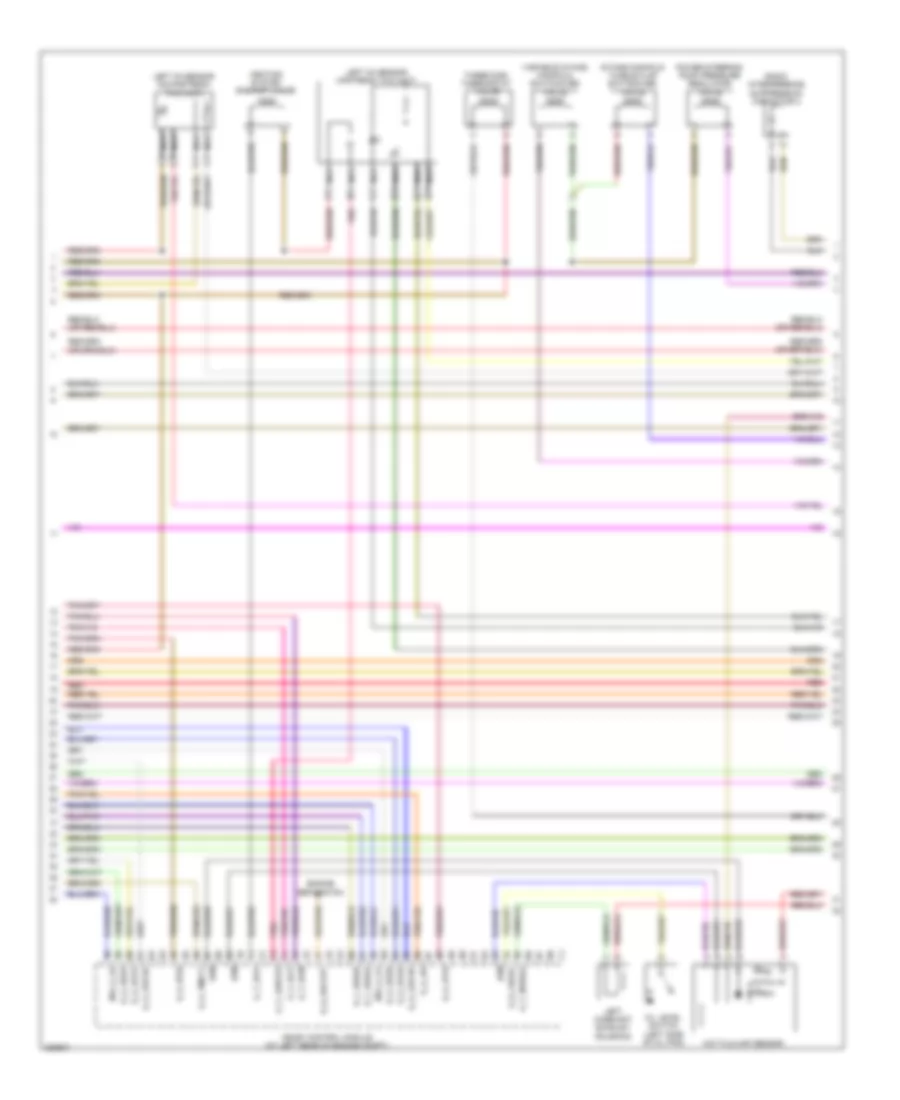
3.0L, Engine Performance Wiring Diagram (2 of 4) for Mercedes-Benz C280 2006
List of elements for 3.0L, Engine Performance Wiring Diagram (2 of 4) for Mercedes-Benz C280 2006:
- Air injection valve
- Air pump
- Coolant temperature sensor (left rear of engine)
- Crankshaft hall sensor (at left rear of engine)
- Left intake manifold tumble flap position sensor (left rear of engine compt)
- Left knock sensor 2 (between cylinder banks)
- Nca
- Pressure sensor
- Red
- Right intake manifold tumble flap position sensor (between engine cylinder banks)
- Right knock sensor 1 (between cylinder banks)
- Right o2 sensor downstream twc (kat)
- Right o2 sensor upstream twc (kat)
- Throttle valve actuator
- W11w1 (on left cylinder bank)
3.0L, Engine Performance Wiring Diagram (3 of 4) for Mercedes-Benz C280 2006
List of elements for 3.0L, Engine Performance Wiring Diagram (3 of 4) for Mercedes-Benz C280 2006:
- A_t_dcm
- A_t_dcp
- A_t_eco
- A_t_lshvk2
- A_t_nwsa2
- D_s_kw out
- Engine separation
- E_a_ds
- E_a_ip1s
- E_a_ip2s
- E_a_ks1a
- E_a_ks1b
- E_a_ks2a
- E_a_ks2b
- E_a_lsu1ia
- E_a_lsu1ip
- E_a_tmot1
- E_f_kwga
- E_f_kwgb
- E_s_fsoel
- Heating system shutoff valve
- Hfm
- Hot film maf sensor
- Intake manifold tumble flap switchover valve
- Left camshaft exhaust solenoid
- Left o2 sensor downstream twc (kat)
- Left o2 sensor upstream twc (kat)
- Me-sfi control module (at left rear of engine compt)
- Nca
- Nw_g_a1
- Nw_g_a2
- Oil level switch (left side of oil pan)
- Pnk
- Power steering pump pressure regulator valve
- Radio interference suppression capacitor 2
- Red
- Three disk thermostat valve
- Variable intake manifold switchover valve
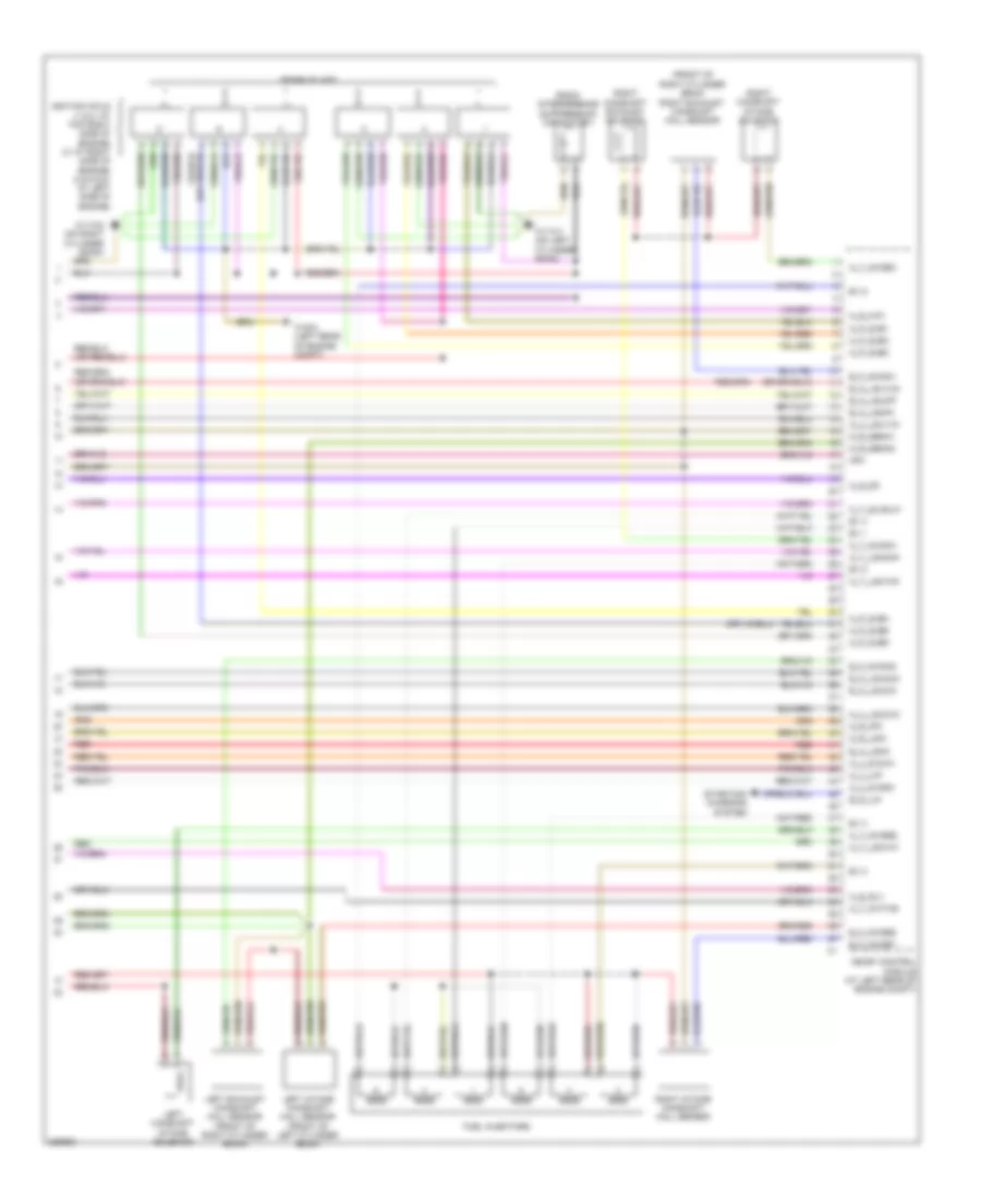
3.0L, Engine Performance Wiring Diagram (4 of 4) for Mercedes-Benz C280 2006
List of elements for 3.0L, Engine Performance Wiring Diagram (4 of 4) for Mercedes-Benz C280 2006:
- (front of right cylinder bank) right exhaust camshaft hall sensor
- A_p_zue1
- A_p_zue2
- A_p_zue3
- A_p_zue4
- A_p_zue5
- A_p_zue6
- A_s_dk
- A_s_hav
- A_s_slv
- A_t_kwths
- A_t_lsh1hk
- A_t_lsh2hk
- A_t_lshvk1
- A_t_nwsa1
- A_t_nwse1
- A_t_nwse2
- A_t_su/suv1
- A_u_5vg1m
- A_u_5vg2m
- A_u_lsu1vm
- A_u_lsu2vm
- A_u_uip
- B_d_lin
- Ev 1
- Ev 2
- Ev 3
- Ev 4
- Ev 5
- Ev 6
- E_a_ls2hk
- E_a_lshk
- E_a_lsu1un
- E_a_lsu2ia
- E_a_lsu2ip
- E_a_lsu2un
- E_f_nwga1
- E_f_nwga2
- E_f_nwge1
- E_f_nwge2
- Fuel injectors
- Hfm
- Ignition coils (1 & 2: at top right side of engine) (3: at right side of engine) (4 & 5 & 6: at left side of engine)
- Left camshaft intake solenoid
- Left exhaust camshaft hall sensor (front of right cylinder bank)
- Left intake camshaft hall sensor (front of left cylinder bank)
- Me-sfi control module (at left rear of engine compt)
- M_r_ipm
- M_r_lsik
- M_r_senm1
- M_r_senm2
- Radio interference suppression capacitor 1
- Red
- Right camshaft exhaust solenoid
- Right camshaft intake solenoid
- Right intake camshaft hall sensor
- Spark plugs
- Starting/ charging system
- W11w1 (on left cylinder bank)
- W11w2 (on right cylinder bank)
- W16/3 (left rear of engine compt)
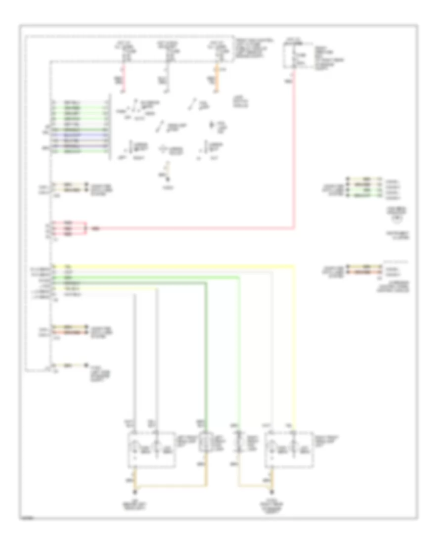
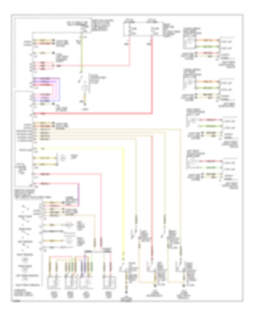
EXTERIOR LIGHTS
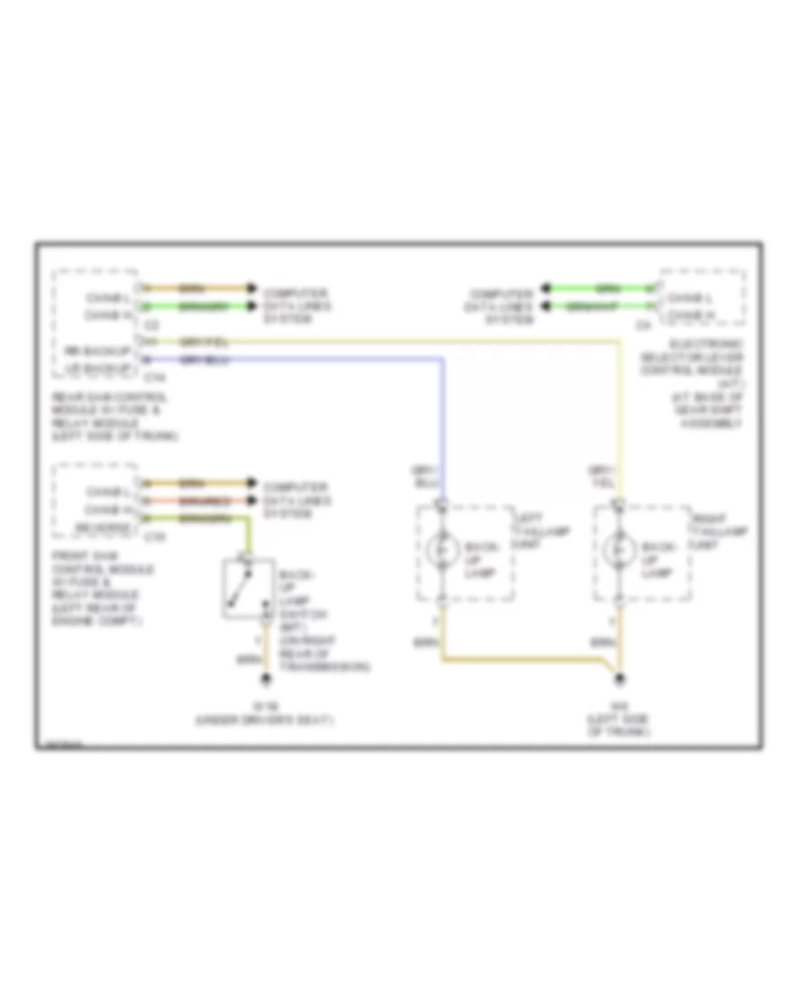
Backup Lamps Wiring Diagram for Mercedes-Benz C280 2006
List of elements for Backup Lamps Wiring Diagram for Mercedes-Benz C280 2006:
- Back- up lamp
- Back- up lamp switch (m/t) (on right rear of transmission)
- C10
- C14
- Can-b h
- Can-b l
- Computer data lines system
- Electronic selector lever control module (a/t) (at base of gear shift assembly
- Front sam control module w/ fuse & relay module (left rear of engine compt)
- Left taillamp unit
- Lr backup
- Rear sam control module w/ fuse & relay module (left side of trunk)
- Reverse
- Right taillamp unit
- Rr backup
- W18 (under driver's seat)
- W6 (left side of trunk)
Exterior Lamps Wiring Diagram (1 of 2) for Mercedes-Benz C280 2006
List of elements for Exterior Lamps Wiring Diagram (1 of 2) for Mercedes-Benz C280 2006:
- (in driver's door)
- 58d
- Auto
- C10
- C13
- C19
- C20
- Can-b h
- Can-b l
- Can-c h
- Can-c l
- Computer data lines system
- Exterior lamps
- Fog lamp
- Fog lamp ind
- Front sam control module w/ fuse & relay module (left rear of engine compt)
- Fuse 5a
- Head
- Headlamp wash
- Hot at all times
- Hot w/ circuit 15r relay energized
- In
- Instrument cluster
- Kpr
- Lamp switch module
- Left
- Left exterior mirror
- Left front door control module
- Left front side marker lamp
- Left headlamp unit
- Left turn ind
- Lf mark
- Lf park
- Lf turn
- Light
- Mirror adjust
- Mirror fold
- Mirror select
- Nca
- Nsl
- Off
- Out
- Park
- Pnk/red
- Red
- Rf mark
- Rf park
- Rf turn
- Right
- Right exterior mirror
- Right front door control module
- Right front side marker lamp
- Right headlamp unit
- Right turn ind
- Sounder
- Sra
- Stand/ park lamp
- Turn
- Turn lamp
- W16/3 (left rear of engine compt)
- W16/4 (right rear of engine compt)
- W28/2
- W9 (behind left headlight)
Exterior Lamps Wiring Diagram (2 of 2) for Mercedes-Benz C280 2006
List of elements for Exterior Lamps Wiring Diagram (2 of 2) for Mercedes-Benz C280 2006:
- (coupe) (sedan & wagon)
- (right side of trunk) w55 w6 (left side of trunk)
- (sedan & wagon)
- 15r
- Back- up lamp
- C14
- C21
- C24
- Can-b h
- Can-b l
- Center high mount stop lamp
- Chmsl
- Combination switch
- Computer data lines system
- Front pre-fuse box (at right rear of engine compt)
- Fuse 200a
- Hazard switch
- Hot at all times
- L license
- Left & right turn signal switch
- Left license plate lamp
- Left rear side marker lamp (coupe)
- Left tail lamp unit
- Left trunk lamp
- Lf backup
- Lf park
- Lf stop
- Lf turn
- Lr mark
- Overhead control panel control module
- Pnk/red
- R license
- Rain/ light sensor (at front of headliner)
- Rear sam control module w/ fuse & relay module (left side of trunk)
- Red
- Right license plate lamp
- Right rear side marker lamp (coupe)
- Right taillamp unit
- Right trunk lamp (sedan & wagon)
- Rr backup
- Rr mark
- Rr park
- Rr stop
- Rr turn
- Steering column module (at top of steering column)
- Stop lamp
- Tail/ park lamp
- Turn signal lamp
- Upper control panel control module
- W28/2
- W6 (left side of trunk)
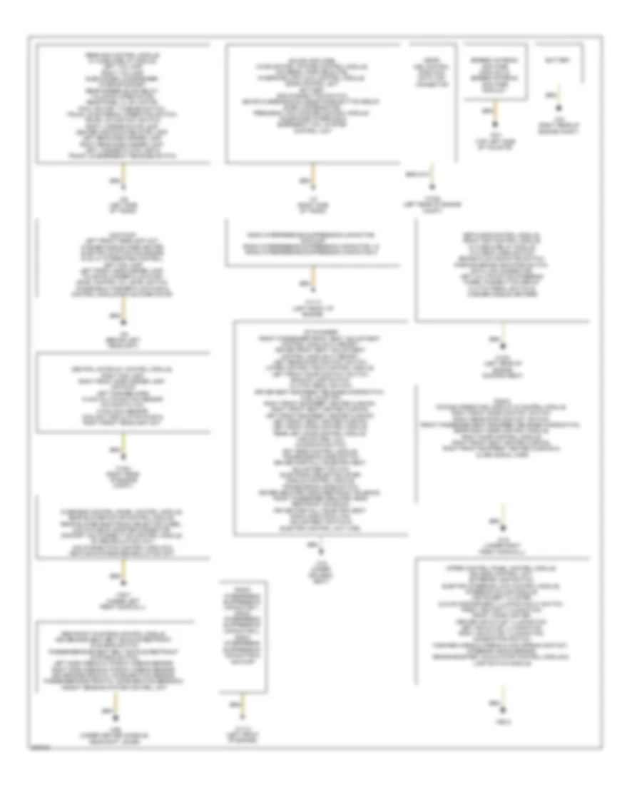
GROUND DISTRIBUTION
Ground Distribution Wiring Diagram for Mercedes-Benz C280 2006
List of elements for Ground Distribution Wiring Diagram for Mercedes-Benz C280 2006:
- Air pump
- Battery
- Cd changer, front passenger front seat adjustment control module w/ memory, driver front seat adjustment control module w/ memory, left rear door contact switch, lower control field control module, left front door contact switch, backup lamp switch, clutch pedal switch, driver seat backrest release microswitch, fuel pump (fp), right front backrest heated cushion, right front seat heated cushion, left front backrest heated cushion, left front seat heated cushion, left front door control module, rear left door control module, fan motors 1 & 2, kickdown switch, ect [egs] control module, transmission mode switch driver partially-elentric seat adjustment switch, electronic selector lever module control module, transmission mode switch, driver neck-pro head restraint solenoid, front passenger neck-pro head restraint solenoid, driver partially-elentric seat radio additional fan, adjustment switch & electric control unit (vgs)
- Central gateway control module, right fog lamp, right front side marker lamp, air pump, left fanfare horn c-aac multifunction sensor (automatic a/c), c-aac sun sensor, coolant circulation pump & right front headlamp unit
- Driver's seat)
- Esp & bas control module, front sam control module w/ fuse & relay module, ata (edw) hood switch, brake fluid indicator switch, parking brake indicator switch, data link connector, left multifunction steering wheel pushbutton group, clutch pedal switch & washer nozzle heaters
- Hcs pump, left front headlamp unit, washer nozzle hose heater, electric suction fan engine & ac w/ integrated control, left fog lamp, left front side marker lamp, tailgate washer fluid pump, level control oil level switch, windshield washer fluid pump & control module box blower motor
- Me-sfi (me) control module & data link connector
- Overhead control panel control module, rear blower motor control module, rear blower electronic selector wheel, can databus adapter connector, comfort aac pushbutton control module, ac recirculation unit, aac pushbutton control module & heating systems recirculation unit
- Radio interferenc suppression capacitor &
- Radio interferenc suppression capacitor 1, radio interferenc suppression capacitor 2,
- Radio interference suppression capacitor, air pump, radio interference suppression capacitor 1 & radio interference suppression capacitor 2
- Radio, comand operating, display & control module right front door contact switch, right rear door contact switch, front passenger seat backrest release microswitch, rear right door control module, right door control module, right front seat heated cushion, right front backrest heated cushion & alarm signal horn
- Rear sam control module w/ fuse & relay module, left taillamp, right taillamp, subwoofer loudspeaker, interior socket, rear screen blind relay, tailgate wiper motor, rear panel cl (zv) motor, pawl rotary tumbler switch, trunk lid external operation switch, trunk lid contact switch, right license plate lamp, center high-mounted stop lamp, left rear side marker lamp, right rear side marker lamp, left license plate lamp & trunk lid emergency release switch
- Restraint systems control module, driver-side seat belt buckle restraint systems switch, passenger-side seat belt buckle restraint systems switch, left side airbag & window airbag sensor, right side airbag & window airbag sensor, driver-side frontal acceleration sensor, passenger-side frontal acceleration sensor & weight sensing system control unit
- Screen antenna amplifier module 2 & screen antenna amplifier module 1
- Sound amplifier, voice control system control module, universal portable ctel interface (upci (uhi)) control module, sdar control unit, battery, sos pushbutton switch, mb-info & breakdown assistance button group, e-net compensator, frequency switchover control module, telephone interface & emergency call system control unit
- Upper control panel control module, eis (ezs) control unit, exterior lamp switch, electric steering lock control module, steering column module, instrument cluster, glove compartment illumination w/ switch, front ashtray illumination, front cigar lighter, center air outlet illumination, left air outlet illumination, right air outlet illumination, combination switch, fanfare horns & airbag clock spring contact, steering angle sensor, brake booster vacuum pump control module & lamp switch module
- W10 (right rear of engine compt)
- W11/3 (left front of engine)
- W16/3 (left rear of engine compartment)
- W16/4 (right rear of engine compt)
- W16/5 (left rear of engine compt)
- W18 (under
- W19 (under right front door sill)
- W26 (under center console, near shift lever)
- W28/1 (under left front door sill)
- W28/2
- W6 (left side of trunk)
- W7 (right side of trunk)
- W8/1 (top left side of tailgate)
- W9 (behind left headlight)
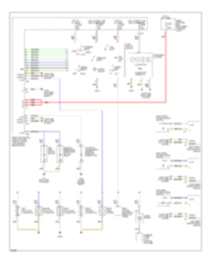
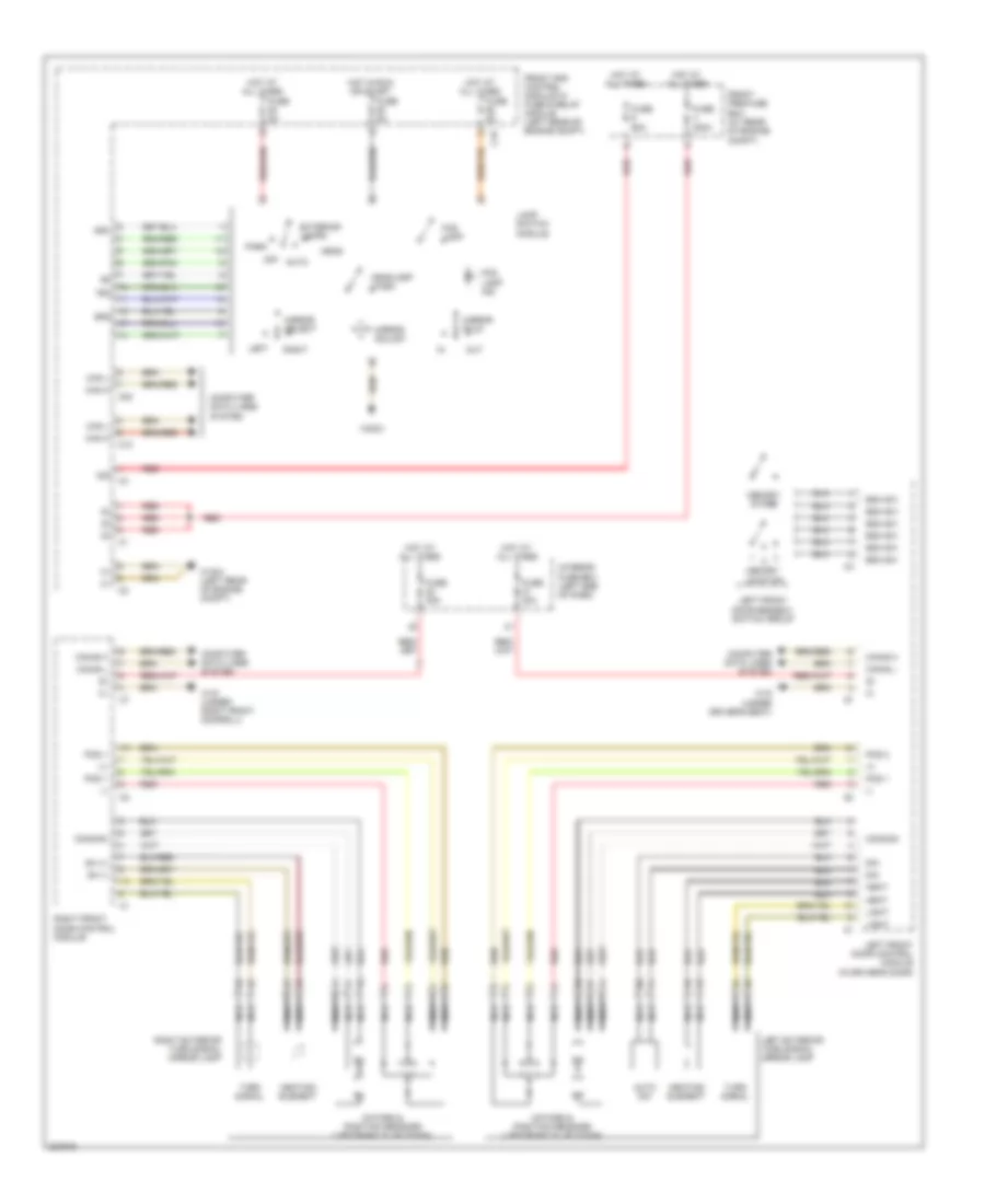
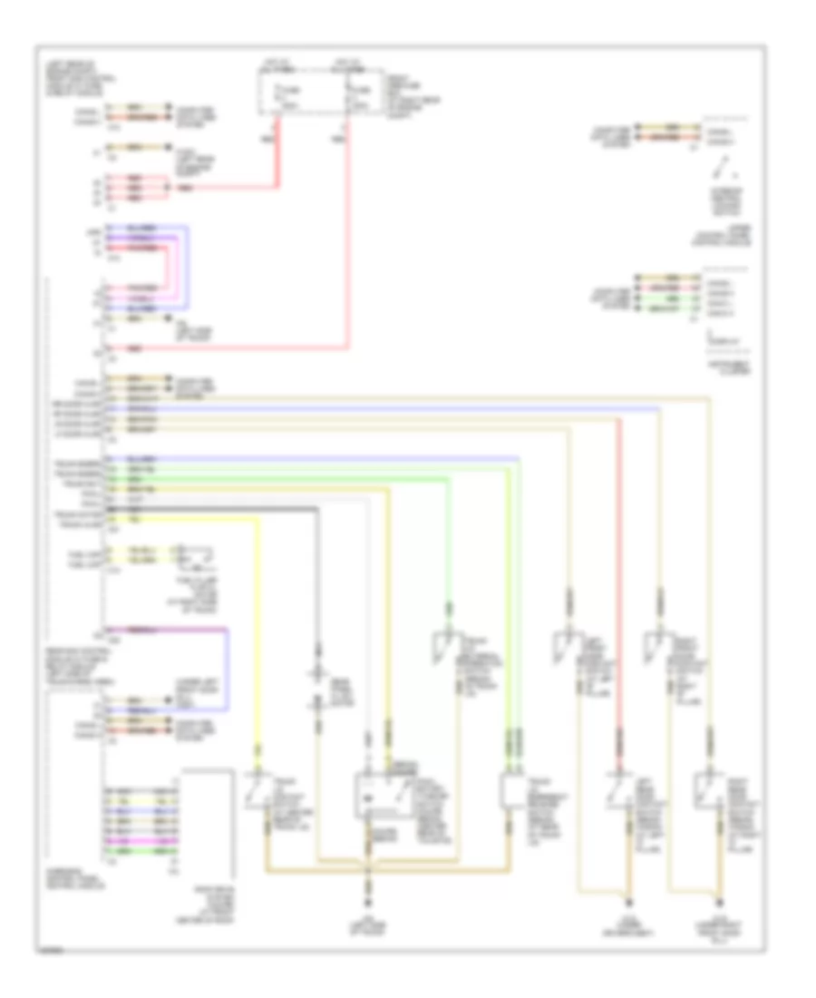
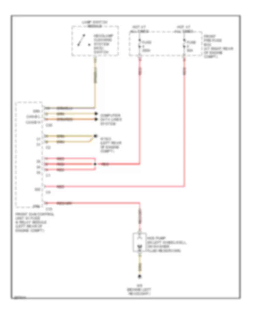
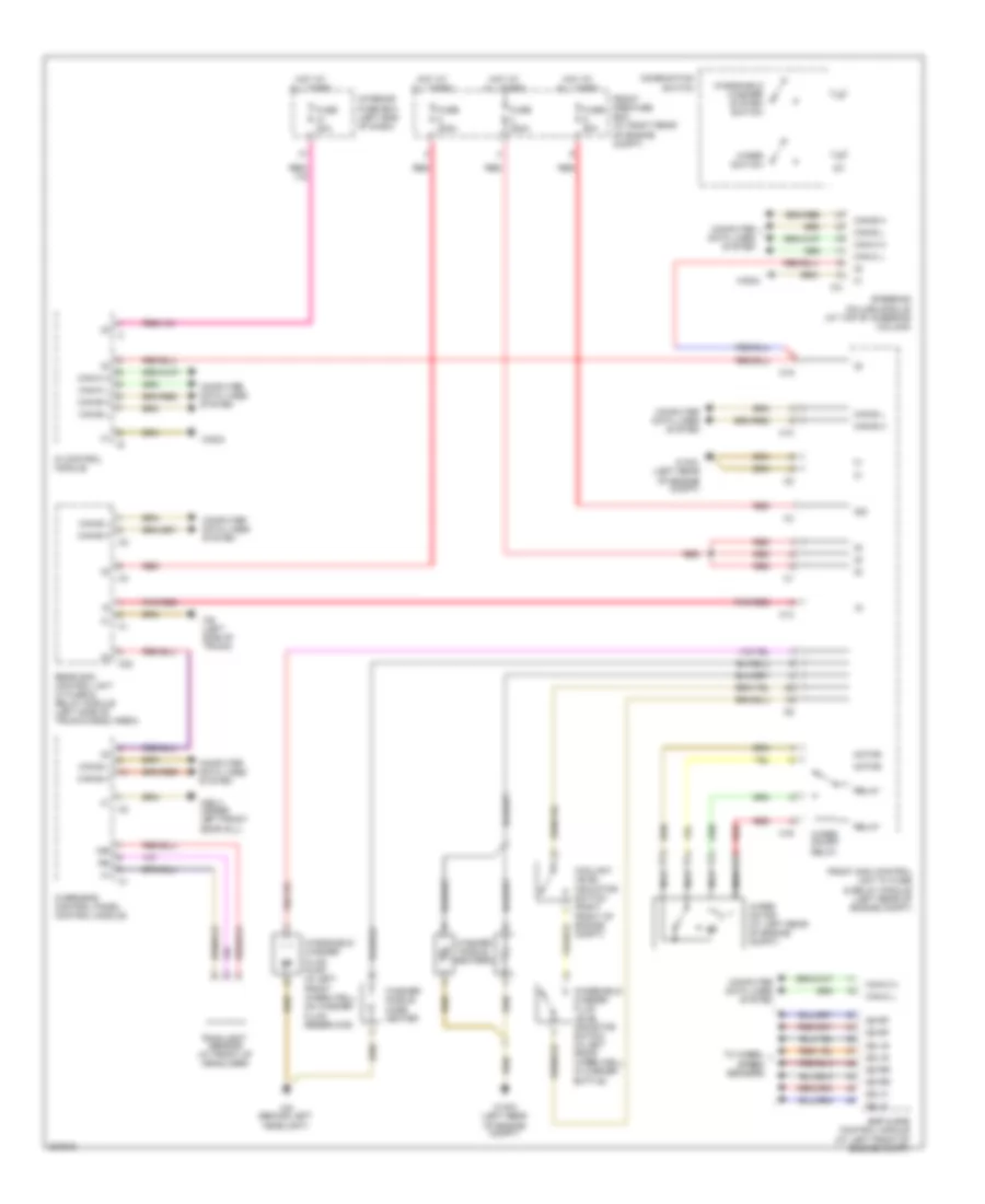
HEADLIGHTS
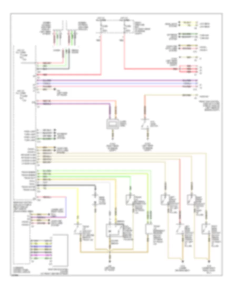
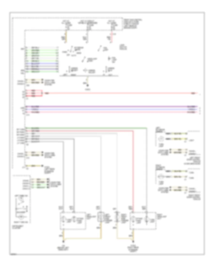
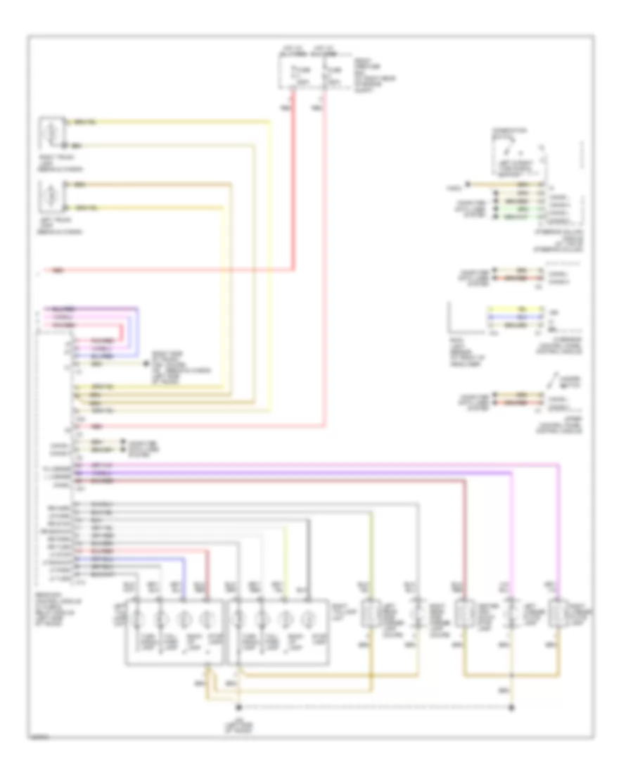
Headlights Wiring Diagram, with Xenon Lamps for Mercedes-Benz C280 2006
List of elements for Headlights Wiring Diagram, with Xenon Lamps for Mercedes-Benz C280 2006:
- Auto
- C10
- C19
- C20
- C24
- Can h
- Can l
- Can-b h
- Can-b l
- Computer data lines system
- Diag
- Exterior lamps
- Fog lamp
- Fog lamp ind
- Front axle sensor (right front wheel house)
- Front pre-fuse box (at right rear of engine compt)
- Front sam control module w/ fuse & relay module (left rear of engine compt)
- Fuse 200a
- Fuse 5a
- Fuse 7.5a
- Head
- Headlamp range adjustment motor
- Headlamp wash
- High beam indicator
- High xenon beam
- Hot at all times
- Hot in run or start
- Instrument cluster
- L fog
- L hi beam
- L lo beam
- Lamp switch module
- Left
- Left front fog lamp
- Left front headlamp unit
- Mirror adjust
- Mirror fold
- Mirror select
- Nsl
- Off
- Out
- Overhead control panel control module
- Park
- R fog
- R hi beam
- R lo beam
- Rear axle sensor (right side of rear axle)
- Red
- Right
- Right front fog lamp
- Right front headlamp unit
- Sra
- W16/3 (left rear of engine compt)
- W16/4 (right rear of engine compt)
- W28/2
- W9 (behind left headlight)
- Xenon beam
- Xenon control module
- Xenon ignition module
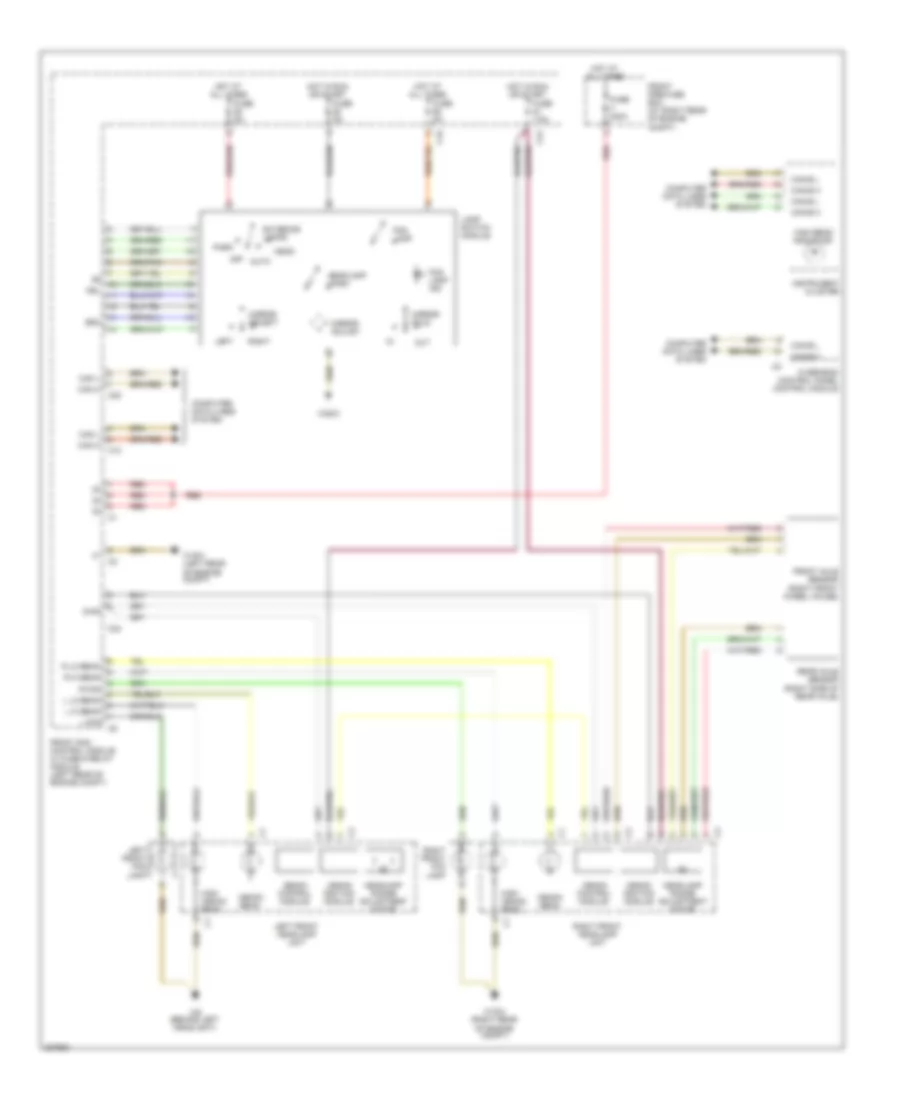
Headlights Wiring Diagram, without Xenon Lamps for Mercedes-Benz C280 2006
List of elements for Headlights Wiring Diagram, without Xenon Lamps for Mercedes-Benz C280 2006:
- Auto
- C10
- C19
- C20
- Can h
- Can l
- Can-b h
- Can-b l
- Computer data lines system
- Exterior lamps
- Fog lamp
- Fog lamp ind
- Front pre-fuse box (at right rear of engine compt)
- Front sam control unit w/ fuse & relay module (left rear of engine compt)
- Fuse 200a
- Fuse 5a
- Head
- Headlamp wash
- High beam
- High beam indicator
- Hot at all times
- Hot in run or start
- Instrument cluster
- L fog
- L hi beam
- L lo beam
- Lamp switch module
- Left
- Left front fog lamp
- Left front headlamp unit
- Low beam
- Mirror adjust
- Mirror fold
- Mirror select
- Nsl
- Off
- Out
- Overhead control panel control module
- Park
- R fog
- R hi beam
- R lo beam
- Red
- Right
- Right front fog lamp
- Right front headlamp unit
- Sra
- W16/3 (left side of engine compt)
- W16/4 (right rear of engine compt)
- W28/2
- W9 (behind left headlight)
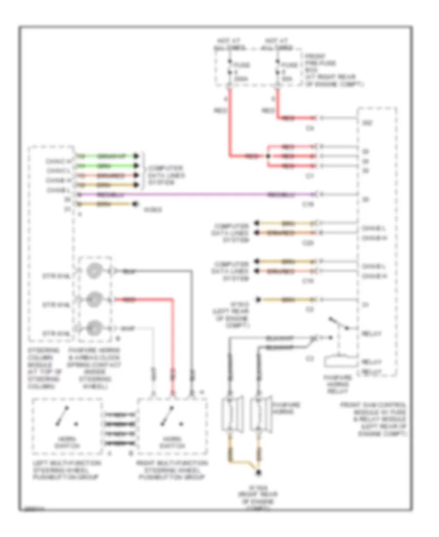
HORN
Horn Wiring Diagram for Mercedes-Benz C280 2006
List of elements for Horn Wiring Diagram for Mercedes-Benz C280 2006:
- 30z
- C10
- C19
- C20
- Can-b h
- Can-b l
- Can-c h
- Can-c l
- Computer data lines system
- Fanfare horns
- Fanfare horns & airbag clock spring contact (inside steering wheel)
- Fanfare horns relay
- Front pre-fuse box (at right rear of engine compt)
- Front sam control module w/ fuse & relay module (left rear of engine compt)
- Fuse 200a
- Fuse 60a
- Horn switch
- Hot at all times
- Left multi-function steering wheel pushbutton group
- Nca
- Red
- Relay
- Right multi-function steering wheel pushbutton group
- Steering column module (at top of steering column)
- Str whl
- W16/3 (left rear of engine compt)
- W16/4 (right rear of engine compt)
- W28/2
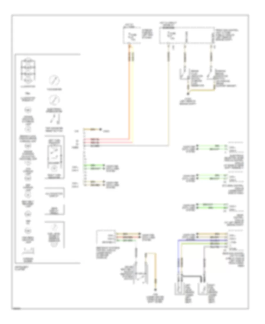
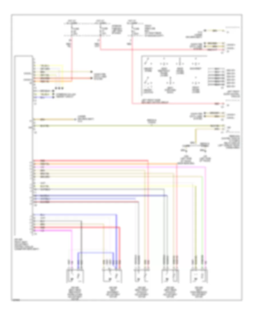
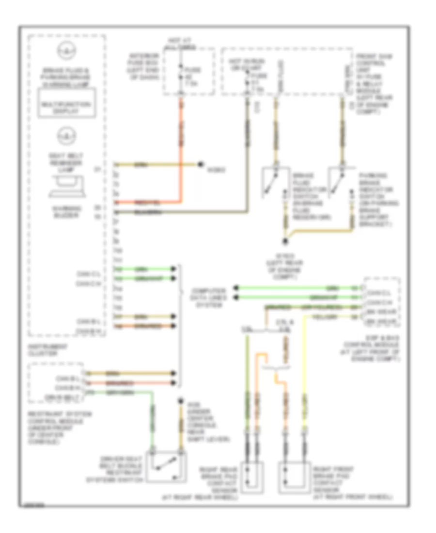
INSTRUMENT CLUSTER
Instrument Cluster Wiring Diagram for Mercedes-Benz C280 2006
List of elements for Instrument Cluster Wiring Diagram for Mercedes-Benz C280 2006:
- (-)
- 15ges
- 31e
- Abs mil
- Air bag indicator & warning lamp
- Brake fluid & parking brake warning lamp
- Brake fluid indicator switch (in brake fluid reservoir)
- Brk fluid
- C19
- Can h
- Can l
- Computer data lines system
- Driver seat belt buckle restraint systems switch
- Drvr belt
- Dtr warning lamp
- Electronic selector lever module control module (at base of gear shift assembly)
- Electronic speedometer
- Engine diagnosis malfuntion indicator lamp
- Esp warning lamp
- Etc (egs) control module (under right side of dash)
- Front sam control unit w/ fuse & relay module (left rear of engine compt)
- Fuel level gauge w/ reserve indicator
- Fuse 7.5a
- Gear display (prndl)
- High beam indicator lamp
- Hot at all times
- Hot w/ circuit 15r relay energized
- Illumination
- Illumination rheostat
- Instrument cluster
- Interior fuse box (left end of dash)
- L fuel
- Left fuel level sensor (under left rear seat)
- Left turn indicator
- Me-sfi control module (at left rear of engine compt)
- Multifunction display
- Nca
- Parking brake indicator switch (on parking brake support braket)
- Prk brk
- R fuel
- Rear sam control unit w/ fuse & relay module (left side of trunk cargo, area)
- Restraint systems control module (under front of center console)
- Right fuel level sensor (under right rear seat)
- Right turn indicator
- Seat belt reminder lamp
- Sounder
- Tachometer
- Trip odometer reset button
- W16/3 (left rear of engine compt)
- W26 (under center console,near shift lever)
- W28/2
- Warning buzzer
Overhead Console Wiring Diagram for Mercedes-Benz C280 2006
List of elements for Overhead Console Wiring Diagram for Mercedes-Benz C280 2006:
- (or pnk)
- 15r
- 15r ais
- 31 ais
- 58d
- Ais
- Ambient lamp
- Automatic dimming mirror
- Backward automatic dimming mirror sensor
- C20
- C22
- C25
- Can-bh
- Can-bl
- Computer data lines system
- Emergency call system control unit (front of cargo area)
- Forward automatic dimming mirror sensor
- Front sam control unit w/ fuse & relay module (left rear of engine compt)
- Fuse 25a
- Garage door opener pushbutton 1
- Garage door opener pushbutton 2
- Garage door opener pushbutton 3
- Garage door opener transmitter unit
- Hot at all times
- Interior lights system
- Interior rearview mirror unit
- Nca
- Overhead control panel control module
- Pnk/red
- Power tops system
- Rain/light sensor (at front of headliner)
- Rear sam control module w/ fuse & relay module (left side of trunk/ cargo area.)
- Sos pushbutton switch
- W28/1 (under left front door sill)
- W7 (right side of trunk)
INTERIOR LIGHTS
Courtesy Lamps Wiring Diagram for Mercedes-Benz C280 2006
List of elements for Courtesy Lamps Wiring Diagram for Mercedes-Benz C280 2006:
- (under left front door sill) w28/1
- (wagon, sedan) left rear door entrance & exit lamp
- (wagon, sedan) right rear door entrance & exit lamp
- C10
- C13
- C17
- C19
- C21
- C22
- C24
- Can-b h
- Can-b l
- Computer data lines system
- Ctsy lmp
- Except wagon
- Front dome
- Front pre-fuse box (at right rear of engine compt)
- Front sam control module w/ fuse & relay module (left rear of engine compt)
- Fuse 15a
- Fuse 200a
- Fuse 25a
- Glove compartment switch & lamp
- Hot at all times
- Hot w/ circuit 15r relay energized
- Left front door contact switch
- Left front door control module
- Left front door entrance & exit lamp
- Left front reading
- Left reading
- Left rear door contact switch (sedan, wagon) (at left "c" pillar)
- Left rear door control
- Left trunk lamp
- Left vanity mirror lamp
- Lf door ajar
- Lr door ajar
- Overhead control panel control module
- Pnk/red
- Rear dome
- Rear dome lamp
- Rear sam control module w/ fuse & relay module (left side of trunk/cargo area)
- Red
- Rf door ajar
- Right front door contact switch (at right "b" pillar)
- Right front door control module
- Right front door entrance & exit lamp
- Right front reading
- Right reading
- Right rear door contact switch (sedan, wagon) (at right "c" pillar)
- Right rear door control module
- Right trunk lamp
- Right vanity mirror lamp
- Rr door ajar
- Trunk ajar
- Trunk lamp
- Trunk lid contact switch (at center rear of trunk lid)
- W16/3 (left rear of engine compt)
- W18 (under driver's seat)
- W19 (under right front door sill)
- W28/2
- W6 (left side of trunk)
- Wagon
Instrument Illumination Wiring Diagram for Mercedes-Benz C280 2006
List of elements for Instrument Illumination Wiring Diagram for Mercedes-Benz C280 2006:
- (-)
- Auto
- Automatic transmission program selector pushbutton
- C10
- C11
- C19
- C20
- C25
- Can-b h
- Can-b l
- Center air outlet illumination
- Clock- spring
- Computer data lines system
- Driver's seat)
- Exterior lamps
- Fog lamp
- Fog lamp ind
- Front ashtray illumination
- Front cigar lighter
- Front pre-fuse box (right rear of engine compt)
- Front sam control module w/ fuse & relay module (left rear of engine compt)
- Fuse 200a
- Fuse 5a
- Fuse 7.5a
- Head
- Headlamp wash
- Hot at all times
- Hot w/ circuit 15r relay energized
- Illum
- Illumination
- Illumination rheostat
- Instrument cluster
- Lamp switch module
- Left
- Left air outlet illumination
- Left rear door control module
- Left rear power window switch
- Mb-info & breakdown assistance button group
- Mirror adjust
- Mirror fold
- Mirror select
- Nca
- Off
- Out
- Park
- Rear blower electronic selector wheel
- Red
- Right
- Right air outlet illumination
- Right front door control module
- Right front power window switch
- Right rear door control module
- Right rear power window switch
- Sos push button switch
- Sra
- Steering wheel multi- function switches
- W16/3 (left rear of engine compt)
- W18 (under
- W28/2
- W7 (right side of trunk)
MEMORY SYSTEMS
Driver"s Memory Seat Wiring Diagram for Mercedes-Benz C280 2006
List of elements for Driver"s Memory Seat Wiring Diagram for Mercedes-Benz C280 2006:
- (+)
- (-)
- (under driver's seat) w18
- 15r
- Backrest
- Can-b h
- Can-b l
- Computer data lines system
- Coupe
- Driver front seat adjustment control module (under driver's seat)
- Driver seat backrest adjustment motor
- Driver seat forward/back adjustment motor
- Driver seat front up/down adjustment motor
- Driver seat head restraint raise/lower adjustment motor
- Driver seat rear up/down adjustment motor
- Esa sw
- Front (raise/ lower)
- Front pre-fuse box (at right rear of engine compt)
- Fuse 200a
- Fuse 30a
- Head restraint (raise/ lower)
- Hot at all times
- Interior fuse box (left end of dash)
- Left front door control module
- Left front door esa (esv) switch group
- Memory location
- Memory store
- Rear (raise/ lower)
- Rear sam control module w/ fuse & relay module (left side of trunk cargo/area)
- Red
- Seat (forward/ back)
- Sedan & wagon
- Steering column memory circuit
- W18 (under driver's seat)
- W55 (left side of trunk, near rear sam)
- W6 (left side of trunk)
Memory Mirrors Wiring Diagram for Mercedes-Benz C280 2006
List of elements for Memory Mirrors Wiring Diagram for Mercedes-Benz C280 2006:
- (+)
- (-)
- 30z
- 58d
- Auto
- Auto dim
- C10
- C19
- C20
- Can h
- Can l
- Can-b h
- Can-b l
- Common
- Computer data lines system
- Dim
- Esa sw
- Exterior lamps
- Fog lamp
- Fog lamp ind
- Front pre-fuse box (at rear of engine compt)
- Front sam control module w/ fuse & relay module (left rear of engine compt)
- Fuse 200a
- Fuse 30a
- Fuse 5a
- Fuse 60a
- Head
- Headlamp wash
- Heat
- Heating element
- Hot at all times
- Hot in run or start
- Interior fuse box (left end of dash)
- Lamp switch module
- Left
- Left exterior turn signal mirror lamp
- Left front door control module (in driver's door)
- Left front door esa(esv) switch group
- Light
- Memory location
- Memory store
- Mirror adjust
- Mirror fold
- Mirror select
- Motors & position sensors (left/right & up/ down)
- Nca
- Nsl
- Off
- Out
- Park
- Pos 1
- Pos 2
- Red
- Right
- Right exterior turn signal mirror lamp
- Right front door control module
- Sh (+)
- Sh (-)
- Sra
- Turn signal
- W16/3 (left rear of engine compt)
- W18 (under driver's seat)
- W19 (under right front doorsill)
- W28/2
Passenger"s Memory Seat Wiring Diagram for Mercedes-Benz C280 2006
List of elements for Passenger"s Memory Seat Wiring Diagram for Mercedes-Benz C280 2006:
- (+)
- (-)
- (under driver's seat) w18
- 15r
- Backrest
- Can-b h
- Can-b l
- Computer data lines system
- Coupe
- Esa sw
- Front (raise/ lower)
- Front passenger front seat adjustment control module (under front passenger's seat)
- Front pre-fuse box (at rear of engine compt)
- Fuse 200a
- Fuse 30a
- Head restraint (raise/ lower)
- Hot at all times
- Interior fuse box (left end of dash)
- Memory location
- Memory store
- Passenger seat backrest adjustment motor
- Passenger seat forward/back adjustment motor
- Passenger seat front up/down adjustment motor
- Passenger seat head restraint raise/lower adjustment motor
- Passenger seat rear up/down adjustment motor
- Rear (raise/ lower)
- Rear sam control module w/ fuse & relay module (left side trunk,cargo area)
- Red
- Right front door control module
- Right front door esa (esv) switch group
- Seat (forward/ back)
- Sedan & wagon
- W18 (under driver's seat)
- W55 (left side of trunk, near rear sam)
- W6 (left side of trunk)
NAVIGATION
COMAND Actuation Wiring Diagram (1 of 2) for Mercedes-Benz C280 2006
List of elements for COMAND Actuation Wiring Diagram (1 of 2) for Mercedes-Benz C280 2006:
- (at left "c" pillar) w29/3
- C10
- C11
- C23
- C24
- Can h
- Can l
- Can-b h
- Can-b l
- Command operating, display & control module
- Computer data lines system
- Coupe
- Emergency call system control unit (w/o sound system) (front of cargo area)
- Fan motor 1
- Fan motor 2
- Front pre-fuse box (at right rear of engine compt)
- Front sam control unit, with fuse & relay module (left rear of engine compt)
- Fuse 200a
- Gps
- Hot at all times
- Most
- Mute
- Nca
- Of tailgate)
- Out
- Pnk
- Radio additional fan (front of center console)
- Rear sam control unit with fuse & relay module (at left side of trunk)
- Red
- Screen antenna amplifier module 1 (wagon) (left rear of roof)
- Screen antenna amplifier module 2 (top left of tailgate)
- Sedan
- W19 (under right front doorsill)
- W8/1 (top left side
- Wagon
- Wake up
- Wake up signal connector
- Walkman seperation point
- Zf1
- Zf2
COMAND Actuation Wiring Diagram (2 of 2) for Mercedes-Benz C280 2006
List of elements for COMAND Actuation Wiring Diagram (2 of 2) for Mercedes-Benz C280 2006:
- (or pnk)
- Bass module loud speaker (sedan)
- Cd changer
- Emergency call system control unit (front of cargo area)
- Gps
- Gps antenna (wagon: at top left of tailgate) (except wagon: at center rear of roof)
- Gps antenna splitter
- Left front door mirror triangle speaker (wagon) (sedan) (coupe)
- Left front door speaker (wagon) (sedan) (coupe)
- Left rear door speaker (wagon) (sedan) (coupe)
- Most
- Nca
- Nca s
- Out
- Pnk
- Right front door mirror triangle speaker (wagon) (sedan) (coupe)
- Right front door speaker (wagon) (sedan) (coupe)
- Right rear door speaker (wagon) (sedan) (coupe)
- Sound amplifier
- W/o sound system
D2B Data Bus Wiring Diagram for Mercedes-Benz C280 2006
List of elements for D2B Data Bus Wiring Diagram for Mercedes-Benz C280 2006:
- Cd changer (in glove compartment)
- Most
- Most in
- Most out
- Radio (or) comand operating, display and control module
- Sdar control unit (at right rear of trunk)
- Sound amplifier
- Universal portable ctel interface (upci [uhi]) control module (under cargo floor)
- Wake-up
- Wake-up signal connector
Voice Activation Wiring Diagram for Mercedes-Benz C280 2006
List of elements for Voice Activation Wiring Diagram for Mercedes-Benz C280 2006:
- (info not available)
- Early production
- Hands-free system microphone group
- Info not available
- Late production
- Mic 1
- Mic 2
- Mic 3
- Mic 4
- Mic gnd
- Most
- Most in
- Most out
- Nca
- Pnk
- Rear sam control unit w/ fuse & relay module (left side of trunk/ cargo area)
- Shield
- Voice control system control module (wagon: at front of cargo area)
- W7 (right side of trunk)
- Wake up
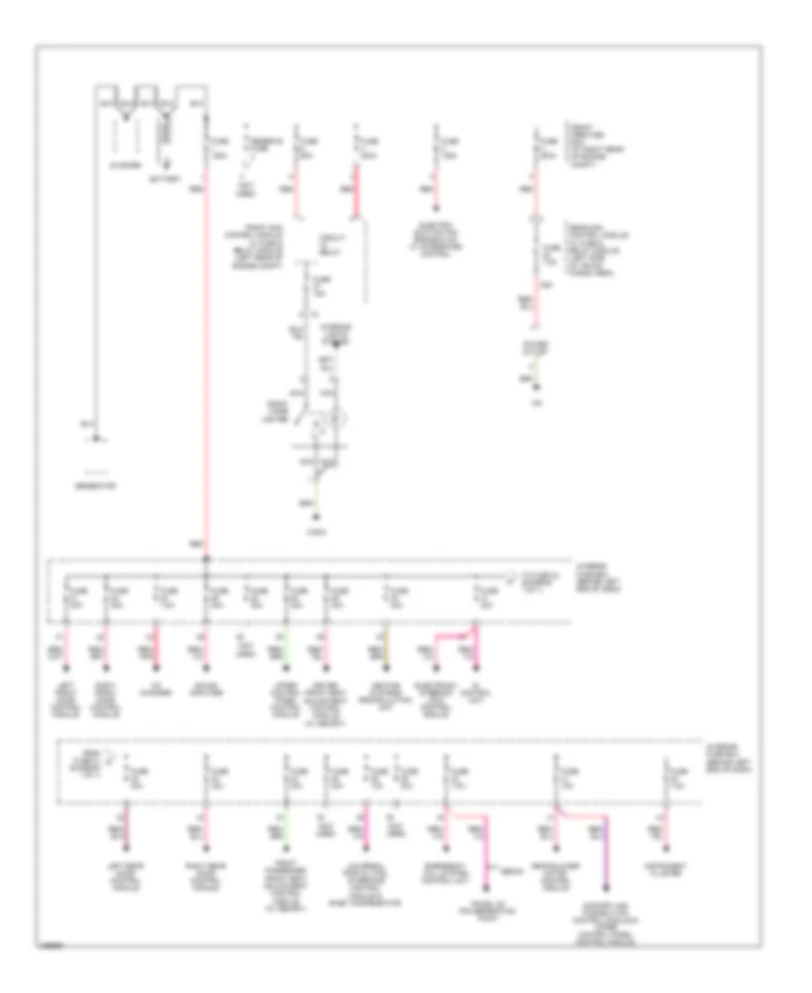
POWER DISTRIBUTION
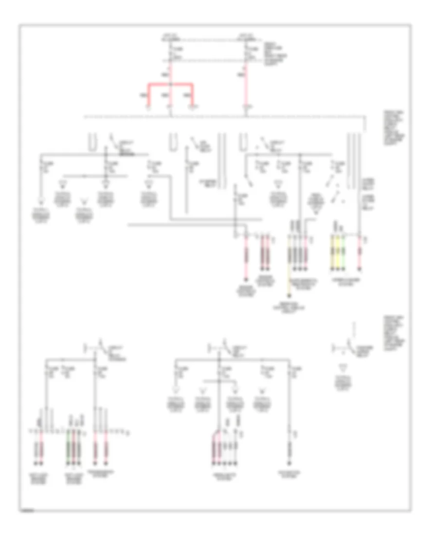
Power Distribution Wiring Diagram for Mercedes-Benz C280 2006
List of elements for Power Distribution Wiring Diagram for Mercedes-Benz C280 2006:
- (diagram 1 of 1)
- (not used)
- Battery
- Cd changer
- Circuit relay
- Comfort aac pushbutton control module & upper control panel control module
- Di control unit
- Driver front seat adjustment control module (w/ memory)
- Electric suction fan engine & a/c w/ integrated control
- Electronic steering lock control module
- Emergency call system control unit
- From fuse 31 a
- Front cigar lighter
- Front passenger front seat adjustment control module (w/ memory)
- Front pre-fuse box (at right rear of engine compt)
- Front sam control module w/ fuse & relay module (left rear of engine compt)
- Fuse 10a
- Fuse 125a
- Fuse 15a
- Fuse 200a
- Fuse 20a
- Fuse 30a
- Fuse 60a
- Fuse 7.5a
- Generator
- Heating systems recirculation unit
- Instrument cluster
- Interior fuse box (behind left end of dash)
- Interior lights system
- Left front door control module
- Left rear door control module
- Nca
- Power outlet
- Rear blower motor control module
- Rear sam control module w/ fuse & relay module (left side of trunk/ cargo area)
- Red
- Red/ pnk
- Reserve fuse
- Right front door control module
- Right rear door control module
- S20
- Sedan
- Sound amplifier
- Starter
- To fuse 32 (diagram 1 of 1)
- Trunk lid/ ffs seperation point
- Universal portal ctel interface control module & e-net compensator
- Upper control panel control module
- W28/2
POWER DOOR LOCKS
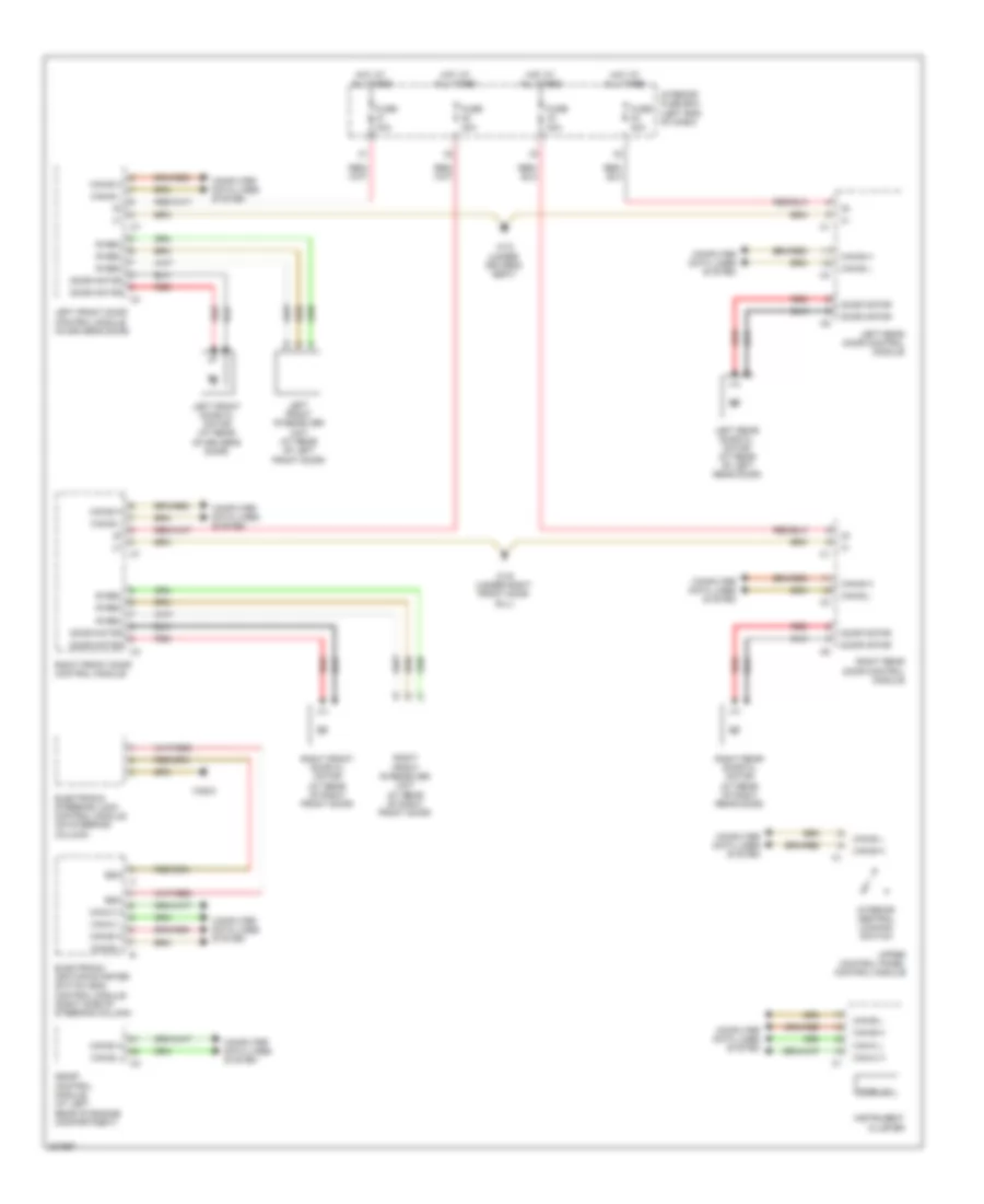
Power Door Locks Wiring Diagram (1 of 2) for Mercedes-Benz C280 2006
List of elements for Power Door Locks Wiring Diagram (1 of 2) for Mercedes-Benz C280 2006:
- (left rear of engine compt) front sam control module w/ fuse & relay module
- (sedan) (coupe)
- (under left front door sill) w28/1
- C10
- C13
- C21
- C22
- Can-b h
- Can-b l
- Can-c h
- Can-c l
- Computer data lines system
- Display
- Front pre-fuse box (at right rear of engine compt)
- Fuel cap
- Fuel filler flap cl motor (at right side of trunk)
- Fuse 200a
- Hot at all times
- Instrument cluster
- Interior central locking switch
- Kpr
- Left front door contact switch (at left "b" pillar)
- Left rear door contact switch (sedan, wagon) (at left "c" pillar)
- Lf door ajar
- Lr door ajar
- Nca
- Overhead control panel control module
- Pawl
- Pawl rotary tumbler switch (coupe, sedan) (center rear of tailgate)
- Pnk/red
- Rear panel cl (zv) motor
- Rear sam control module w/ fuse & relay module (left side of trunk/cargo area)
- Red
- Rf door ajar
- Right front door contact switch (at right "b" pillar)
- Right rear door contact switch (sedan, wagon) (at right "c" pillar)
- Roof drive system (coupe) (at front center of roof)
- Rr door ajar
- Trunk ajar
- Trunk emerg
- Trunk ext
- Trunk lid contact switch (at center rear of trunk lid)
- Trunk lid emergency release switch (sedan) (at rear of trunk lid)
- Trunk lid external operation switch (sedan) (in trunk lid)
- Trunk motor
- Upper control panel control module
- W16/3 (left rear of engine compt)
- W18 (under driver's seat)
- W19 (under right front door sill)
- W6 (left side of trunk)
Power Door Locks Wiring Diagram (2 of 2) for Mercedes-Benz C280 2006
List of elements for Power Door Locks Wiring Diagram (2 of 2) for Mercedes-Benz C280 2006:
- Can-b h
- Can-b l
- Can-c h
- Can-c l
- Computer data lines system
- Door motor
- Driver's seat)
- Esp & bas control module (at left front of engine compt)
- Fuse 30a
- Hot at all times
- Interior fuse box (left end of dash)
- Ir rec
- Left front door cl motor (at rear of driver's door)
- Left front door control module (in driver's door)
- Left front ir receiver unit (at rear of left front door)
- Left rear door cl motor (at rear of left rear door)
- Left rear door control module
- Red
- Right front door cl motor (at rear of right front door)
- Right front door control module
- Right front ir receiver unit (at rear of right front door)
- Right rear door cl motor (at rear of right rear door)
- Right rear door control module
- Ss lf
- Ss lr
- Ss rf
- Ss rr
- To wheel speed sensors
- W18 (under
- W19 (under right front door sill)
POWER MIRRORS
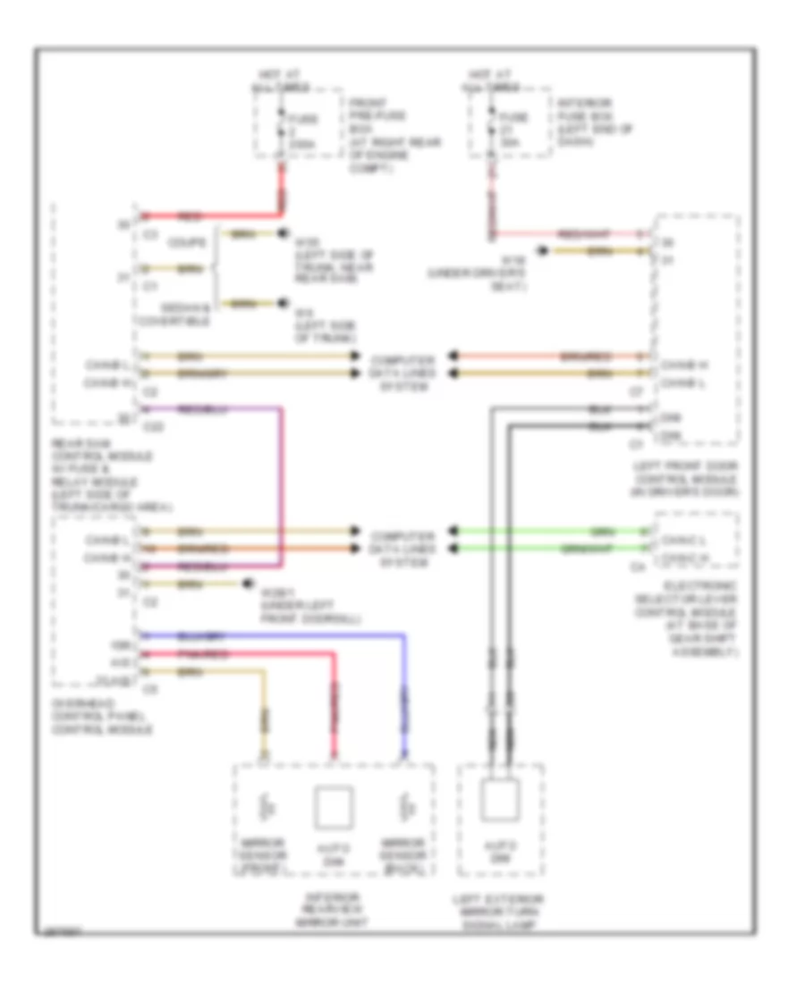
Electrochromic Mirror Wiring Diagram for Mercedes-Benz C280 2006
List of elements for Electrochromic Mirror Wiring Diagram for Mercedes-Benz C280 2006:
- 15r
- 31 ais
- Ais
- Auto dim
- C22
- Can-b h
- Can-b l
- Can-c h
- Can-c l
- Computer data lines system
- Coupe
- Dim
- Electronic selector lever control module (at base of gear shift assembly)
- Front pre-fuse box (at right rear of engine compt)
- Fuse 200a
- Fuse 30a
- Hot at all times
- Interior fuse box (left end of dash)
- Interior rearview mirror unit
- Left exterior mirror turn signal lamp
- Left front door control module (in driver's door)
- Mirror sensor (back)
- Mirror sensor (front)
- Nca
- Overhead control panel control module
- Pnk/red
- Rear sam control module w/ fuse & relay module (left side of trunk/cargo area)
- Red
- Sedan & covertible
- W18 (under driver's seat)
- W28/1 (under left front doorsill)
- W55 (left side of trunk, near rear sam)
- W6 (left side of trunk)
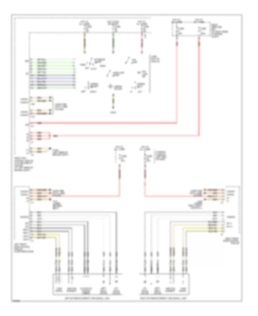
Power Mirror Wiring Diagram for Mercedes-Benz C280 2006
List of elements for Power Mirror Wiring Diagram for Mercedes-Benz C280 2006:
- 30z
- 58d
- Auto
- Automatic dimming mirror
- C10
- C19
- C20
- Can-b h
- Can-b l
- Common
- Computer data lines system
- Dim
- Exterior lamps
- Fog lamp
- Fog lamp ind
- Front pre-fuse box (at right rear of engine compt)
- Front sam control module w/ fuse & relay module (at left rear of engine compt)
- Fuse 200a
- Fuse 30a
- Fuse 5a
- Fuse 60a
- Head
- Headlamp wash
- Heat
- Heating element
- Hot at all times
- Hot in run or start
- Interior fuse box (left end of dash)
- Lamp switch module
- Left
- Left exterior mirror turn signal lamp
- Left front door control module (in driver's door)
- Left/ right motor
- Light
- Mirror adjust
- Mirror fold
- Mirror select
- Nca
- Off
- Out
- Park
- Red
- Right
- Right exterior mirror turn signal lamp
- Right front door control module
- Sh (+)
- Sh (-)
- Turn signal
- Up/ down motor
- W16/3 (left rear of engine compt)
- W18 (under driver's seat)
- W19 (under right front door sill)
- W28/2
POWER SEATS
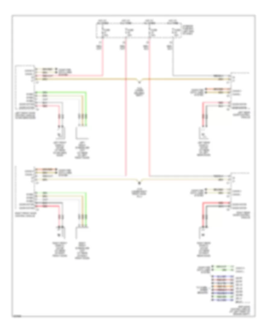
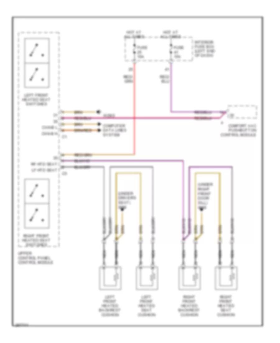
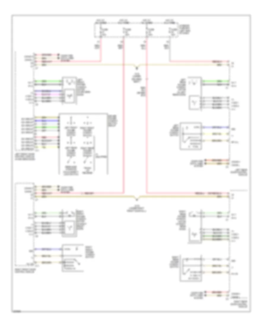
Heated Seats Wiring Diagram for Mercedes-Benz C280 2006
List of elements for Heated Seats Wiring Diagram for Mercedes-Benz C280 2006:
- (under driver's seat) w18
- (under right front door sill) w19
- Can-b h
- Can-b l
- Comfort aac pushbutton control module
- Computer data lines system
- Fuse 10a
- Fuse 15a
- Hot at all times
- Interior fuse box (left end of dash)
- Left front heated backrest cushion
- Left front heated seat cushion
- Left front heated seat switches
- Lf htd seat
- Nca
- Rf htd seat
- Right front heated backrest cushion
- Right front heated seat cushion
- Right front heated seat switches
- Upper control panel control module
- W28/2
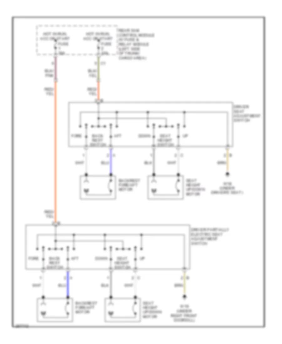
Power Seats Wiring Diagram for Mercedes-Benz C280 2006
List of elements for Power Seats Wiring Diagram for Mercedes-Benz C280 2006:
- Aft
- Back rest switch
- Backrest fore/aft motor
- Down
- Driver partially electric seat adjustment switch
- Driver seat adjustment switch
- Fore
- Fuse 30a
- Hot in run, acc or start
- Rear sam control module w/ fuse & relay module (left side of trunk/ cargo area)
- Seat height switch
- Seat height up/down motor
- W18 (under driver's seat)
- W19 (under right front doorsill)
POWER TOP/SUNROOF
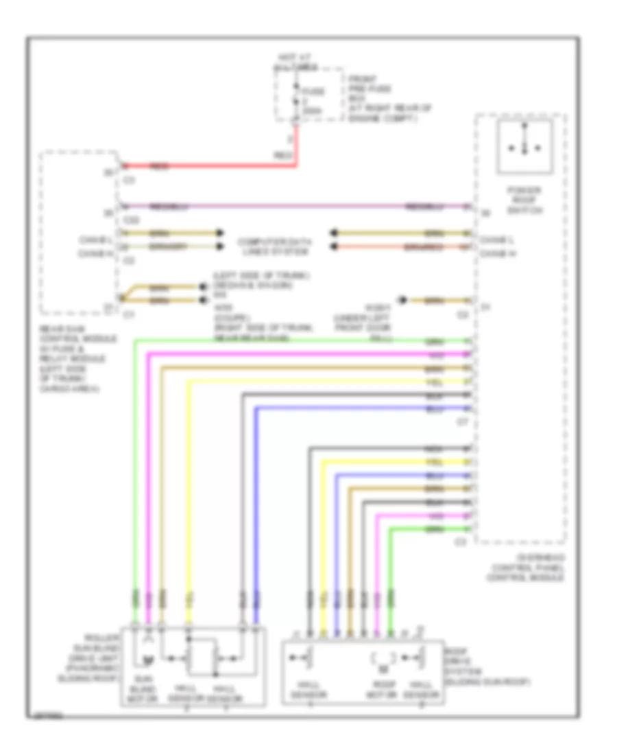
Power Top/Sunroof Wiring Diagram for Mercedes-Benz C280 2006
List of elements for Power Top/Sunroof Wiring Diagram for Mercedes-Benz C280 2006:
- (left side of trunk) (sedan & wagon) w6
- C22
- Can-b h
- Can-b l
- Computer data lines system
- Front pre-fuse box (at right rear of engine compt)
- Fuse 200a
- Hall sensor
- Hot at all times
- Nca
- Overhead control panel control module
- Power roof switch
- Rear sam control module w/ fuse & relay module (left side of trunk/ cargo area)
- Red
- Roller sun blind drive unit (panoramic sliding roof)
- Roof drive system (sliding sun roof)
- Roof motor
- Sun blind motor
- W28/1 (under left front door sill)
- W55 (coupe) (right side of trunk, near rear sam)
POWER WINDOWS
Power Windows Wiring Diagram for Mercedes-Benz C280 2006
List of elements for Power Windows Wiring Diagram for Mercedes-Benz C280 2006:
- (+)
- (-)
- 58d
- C11
- Can-b h
- Can-b l
- Computer data lines system
- Driver power window switch group
- Driver's seat)
- Fh h
- Fh t
- Fh vr
- Fuse 30a
- H (-)
- H sig 1
- H sig 2
- Hot at all times
- If equipped
- Interior fuse box (left end of dash)
- Left front door control module (in driver's door)
- Left front power window motor (in driver's door)
- Left front power window switch
- Left rear door control module
- Left rear power window motor (in left rear door)
- Left rear power window switch
- Rear side windows child safety lock switch
- Red
- Rf w/l
- Right front door control module
- Right front power window motor (in right front door)
- Right front power window switch
- Right rear door control module
- Right rear power window motor (in right rear door)
- Right rear power window switch
- Sw group
- Trunk lid release
- W18 (under
- W19 (under right front door sill)
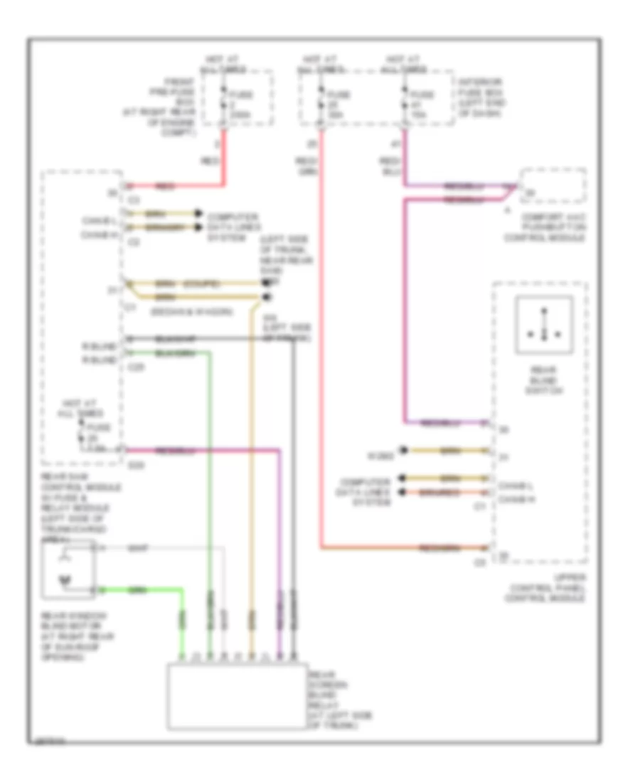
Rear Window Sun Shade Wiring Diagram for Mercedes-Benz C280 2006
List of elements for Rear Window Sun Shade Wiring Diagram for Mercedes-Benz C280 2006:
- (coupe)
- (left side of trunk, near rear sam) w55
- (sedan & wagon)
- C25
- Can-b h
- Can-b l
- Comfort aac pushbutton control module
- Computer data lines system
- Front pre-fuse box (at right rear of engine compt)
- Fuse 15a
- Fuse 200a
- Fuse 30a
- Fuse 7.5a
- Hot at all times
- Interior fuse box (left end of dash)
- R blind
- Rear blind switch
- Rear sam control module w/ fuse & relay module (left side of trunk/cargo area)
- Rear screen blind relay (at left side of trunk)
- Rear window blind motor (at right rear of sun roof opening)
- Red
- S20
- Upper control panel control module
- W28/2
- W6 (left side of trunk)
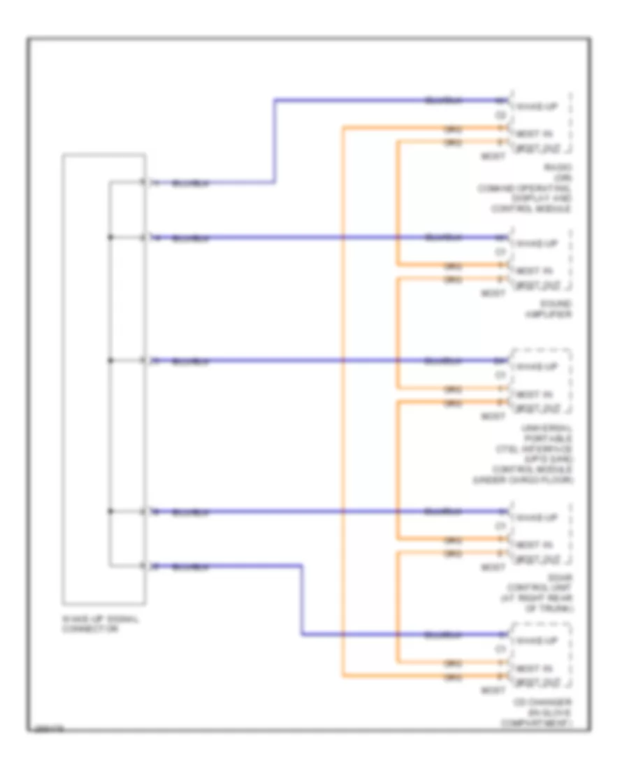
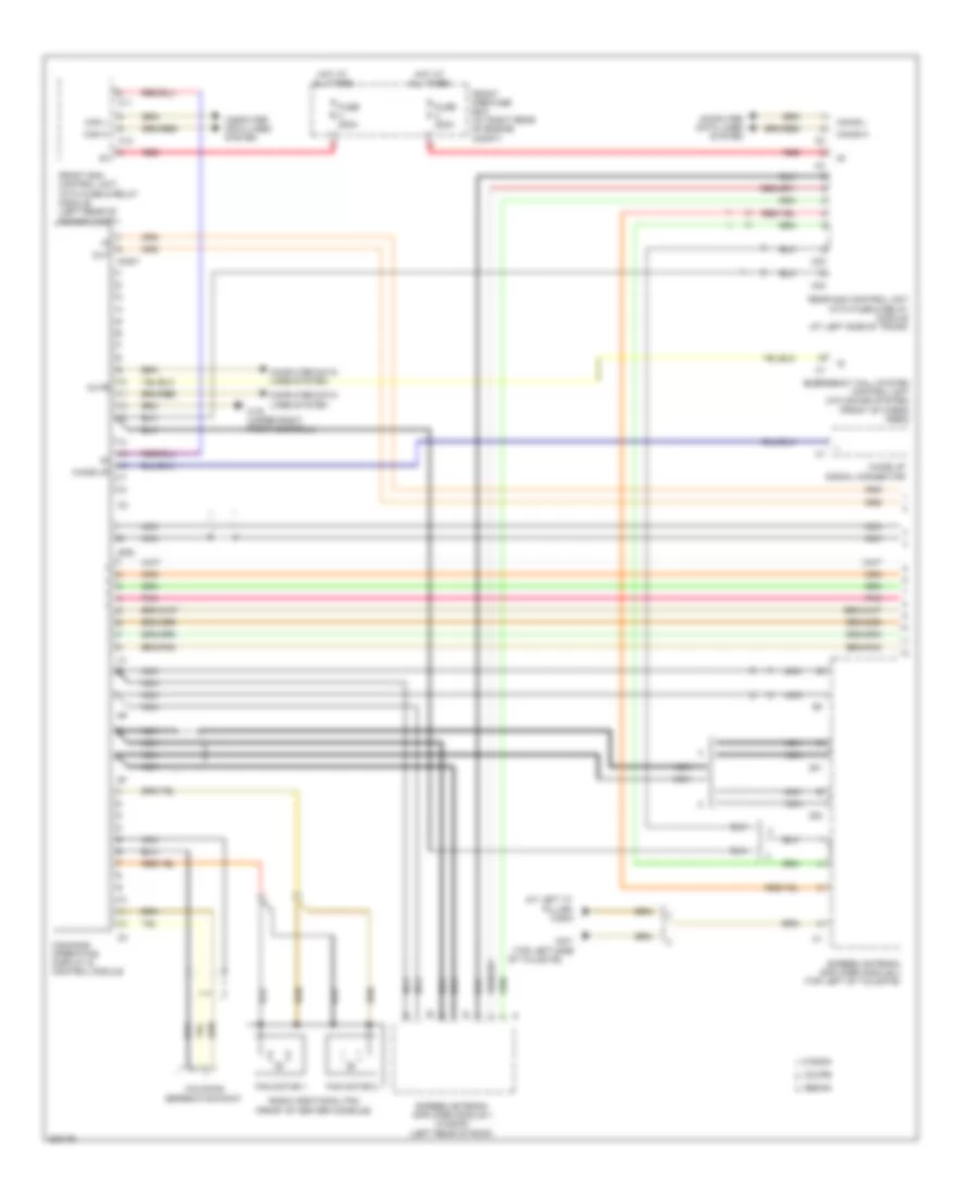
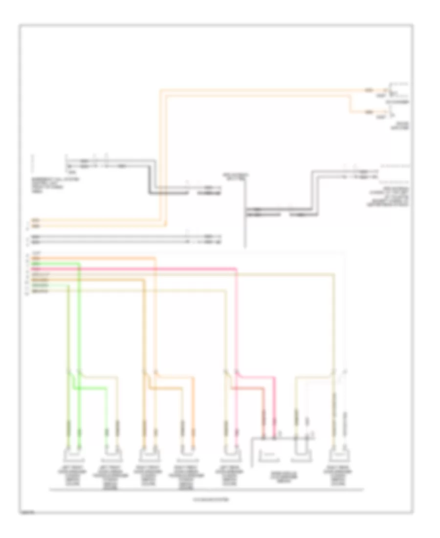
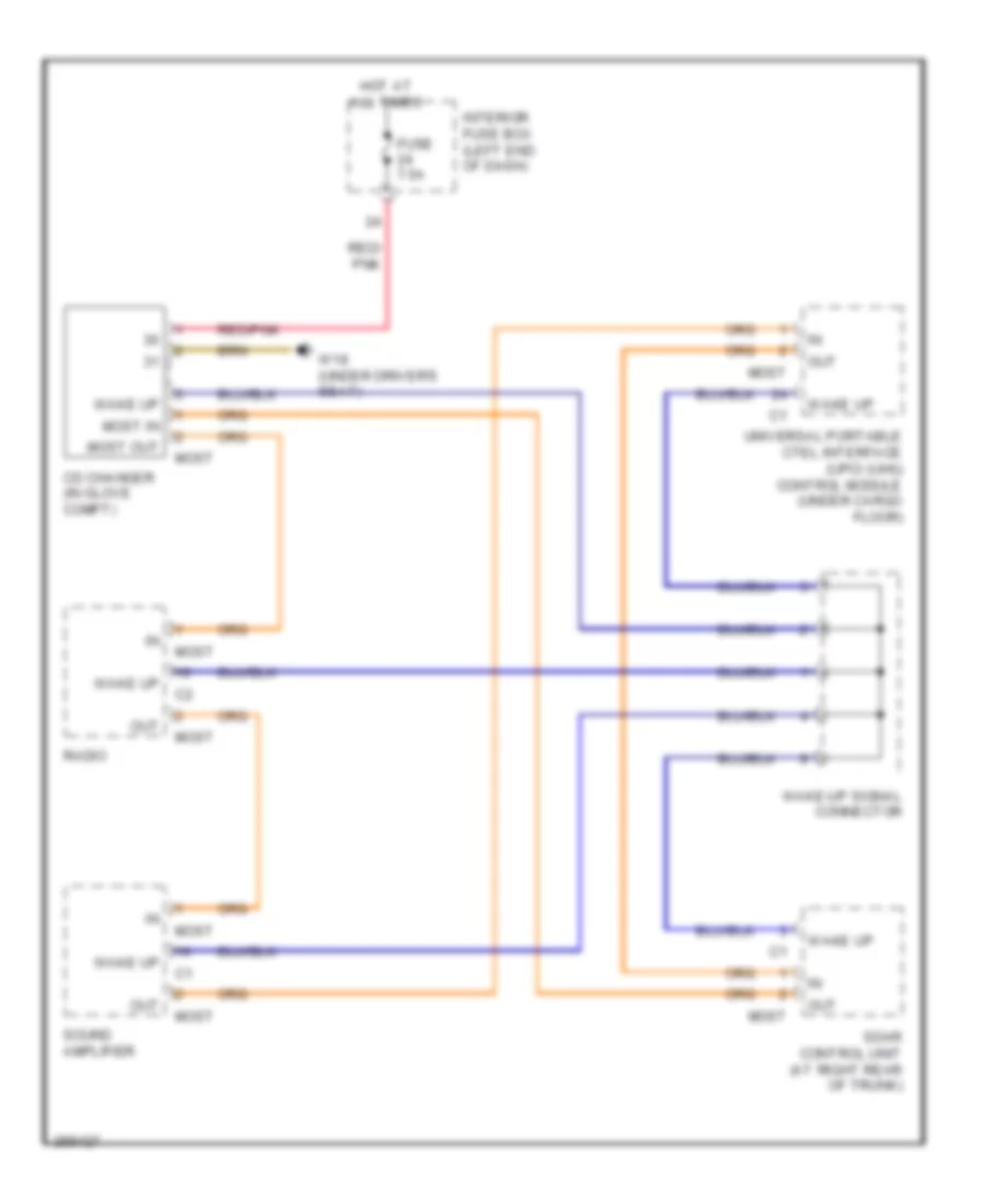
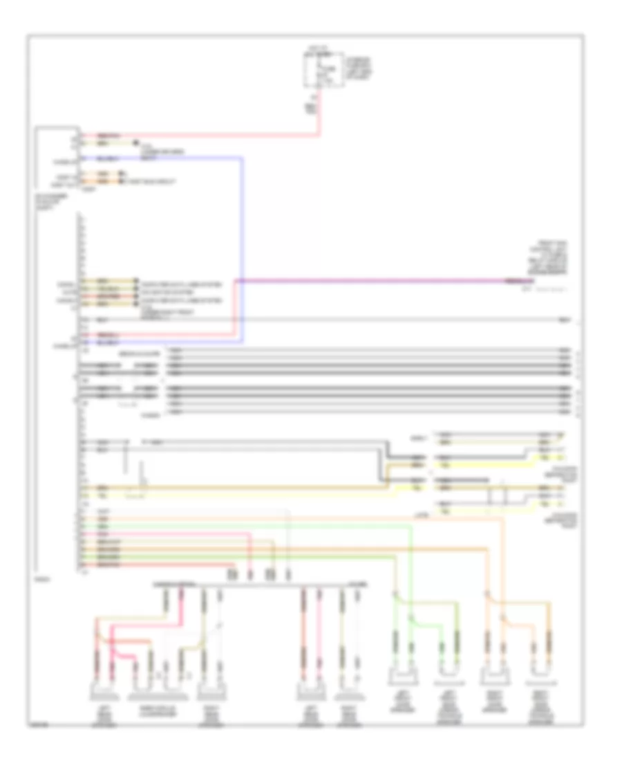
RADIO
COMAND Actuation Wiring Diagram (1 of 2) for Mercedes-Benz C280 2006
List of elements for COMAND Actuation Wiring Diagram (1 of 2) for Mercedes-Benz C280 2006:
- (at left "c" pillar) w29/3
- C10
- C11
- C23
- C24
- Can h
- Can l
- Can-b h
- Can-b l
- Command operating, display & control module
- Computer data lines system
- Coupe
- Emergency call system control unit (w/o sound system) (front of cargo area)
- Fan motor 1
- Fan motor 2
- Front pre-fuse box (at right rear of engine compt)
- Front sam control unit, with fuse & relay module (left rear of engine compt)
- Fuse 200a
- Gps
- Hot at all times
- Most
- Mute
- Nca
- Of tailgate)
- Out
- Pnk
- Radio additional fan (front of center console)
- Rear sam control unit with fuse & relay module (at left side of trunk)
- Red
- Screen antenna amplifier module 1 (wagon) (left rear of roof)
- Screen antenna amplifier module 2 (top left of tailgate)
- Sedan
- W19 (under right front doorsill)
- W8/1 (top left side
- Wagon
- Wake up
- Wake up signal connector
- Walkman seperation point
- Zf1
- Zf2
COMAND Actuation Wiring Diagram (2 of 2) for Mercedes-Benz C280 2006
List of elements for COMAND Actuation Wiring Diagram (2 of 2) for Mercedes-Benz C280 2006:
- (or pnk)
- Bass module loud speaker (sedan)
- Cd changer
- Emergency call system control unit (front of cargo area)
- Gps
- Gps antenna (wagon: at top left of tailgate) (except wagon: at center rear of roof)
- Gps antenna splitter
- Left front door mirror triangle speaker (wagon) (sedan) (coupe)
- Left front door speaker (wagon) (sedan) (coupe)
- Left rear door speaker (wagon) (sedan) (coupe)
- Most
- Nca
- Nca s
- Out
- Pnk
- Right front door mirror triangle speaker (wagon) (sedan) (coupe)
- Right front door speaker (wagon) (sedan) (coupe)
- Right rear door speaker (wagon) (sedan) (coupe)
- Sound amplifier
- W/o sound system
MOST Data Bus Wiring Diagram for Mercedes-Benz C280 2006
List of elements for MOST Data Bus Wiring Diagram for Mercedes-Benz C280 2006:
- Cd changer (in glove compt)
- Fuse 7.5a
- Hot at all times
- Interior fuse box (left end of dash)
- Most
- Most in
- Most out
- Out
- Radio
- Red/ pnk
- Red/pnk
- Sdar control unit (at right rear of trunk)
- Sound amplifier
- Universal portable ctel interface (upci (uhi)) control module (under cargo floor)
- W18 (under driver's seat)
- Wake up
- Wake-up signal connector
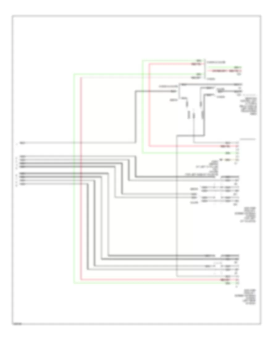
Radio Wiring Diagram (1 of 2) for Mercedes-Benz C280 2006
List of elements for Radio Wiring Diagram (1 of 2) for Mercedes-Benz C280 2006:
- Bass module loudspeaker
- C11
- Can-b h
- Can-b l
- Cd changer (in glove compt)
- Computer data lines system
- Coupe
- Early
- Front sam control unit w/ fuse & relay module (left rear of engine compt)
- Fuse 7.5a
- Hot at all times
- Interior fuse box (left end of dash)
- Late
- Left front door mirror triangle speaker
- Left front door speaker
- Left rear door speaker
- Most
- Most bus circuit
- Most in
- Most out
- Mute
- Navigation system
- Nca
- Pnk
- Radio
- Red/ pnk
- Red/pnk
- Right front door mirror triangle speaker
- Right front door speaker
- Right rear door speaker
- Sedan & coupe
- W18 (under driver's seat)
- W19 (under right front door sill)
- Wagon
- Wagon & sedan
- Wake up
- Walkman separation point
Radio Wiring Diagram (2 of 2) for Mercedes-Benz C280 2006
List of elements for Radio Wiring Diagram (2 of 2) for Mercedes-Benz C280 2006:
- Amplifier module 1, screen antenna (wagon) (left rear of roof)
- Amplifier module 2, screen antenna (wagon) (top left of tailgate)
- C23
- Coupe
- Nca
- Rear sam control unit w/ fuse & relay module (left side of trunk/cargo area)
- Sedan
- W29/3 (sedan) (at left "c" pillar) w8/1 (coupe) (top left side of tailgate)
- Wagon
- Wagon & coupe
- Zf1
- Zf2
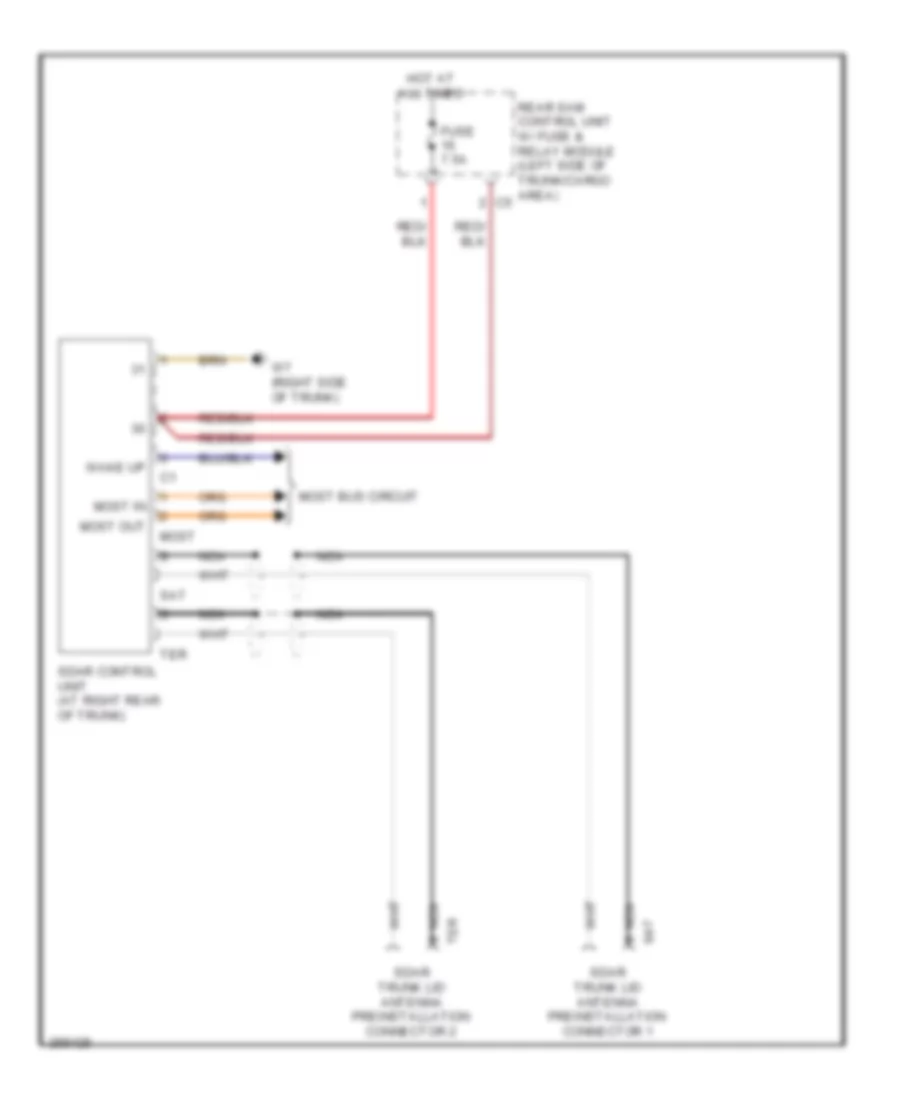
Satellite Radio Wiring Diagram for Mercedes-Benz C280 2006
List of elements for Satellite Radio Wiring Diagram for Mercedes-Benz C280 2006:
- Fuse 7.5a
- Hot at all times
- Most
- Most bus circuit
- Most in
- Most out
- Nca
- Rear sam control unit w/ fuse & relay module (left side of trunk/cargo area) c5
- Sat
- Sdar control unit (at right rear of trunk)
- Sdar trunk lid antenna preinstallation connector 1
- Sdar trunk lid antenna preinstallation connector 2
- Ter
- W7 (right side of trunk)
- Wake up
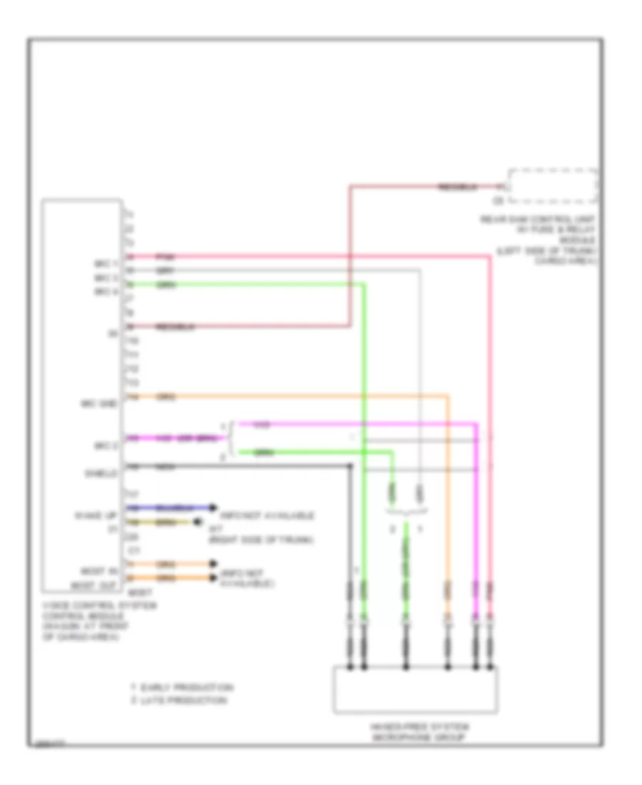
Voice Activation Wiring Diagram for Mercedes-Benz C280 2006
List of elements for Voice Activation Wiring Diagram for Mercedes-Benz C280 2006:
- (info not available)
- Early production
- Hands-free system microphone group
- Info not available
- Late production
- Mic 1
- Mic 2
- Mic 3
- Mic 4
- Mic gnd
- Most
- Most in
- Most out
- Nca
- Pnk
- Rear sam control unit w/ fuse & relay module (left side of trunk/ cargo area)
- Shield
- Voice control system control module (wagon: at front of cargo area)
- W7 (right side of trunk)
- Wake up
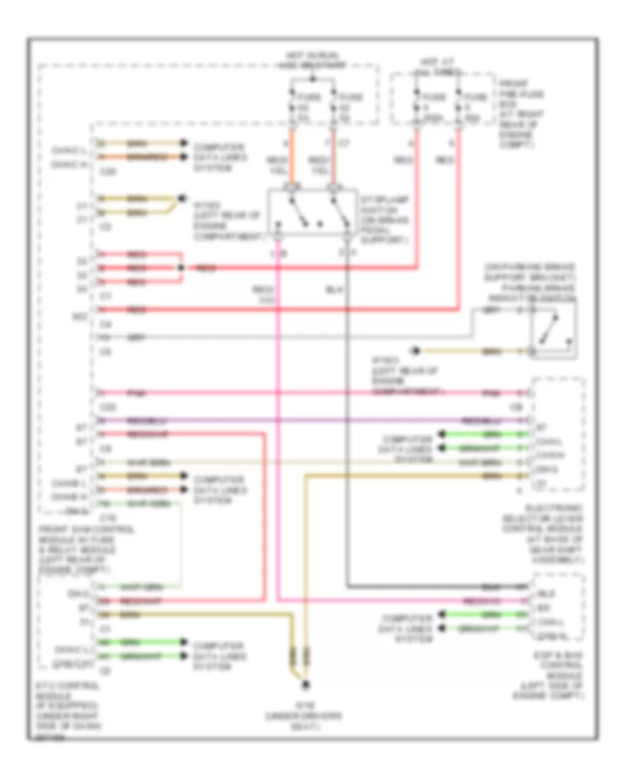
SHIFT INTERLOCK
Shift Interlock Wiring Diagram for Mercedes-Benz C280 2006
List of elements for Shift Interlock Wiring Diagram for Mercedes-Benz C280 2006:
- (on parking brake support bracket) parking brake indicator switch
- 30z
- C10
- C20
- C22
- Can h
- Can l
- Can-b h
- Can-b l
- Can-c h
- Can-c l
- Computer data lines system
- Diag
- Electronic selector lever control module (at base of gear shift assembly)
- Esp & bas control module (left side of engine compt)
- Etc control module (if equipped) (under right side of dash)
- Front pre-fuse box (at right rear of engine compt)
- Front sam control module w/ fuse & relay module (left rear of engine compt)
- Fuse 200a
- Fuse 5a
- Fuse 60a
- Hot at all times
- Hot in run, acc or start
- Mls
- Pnk
- Red
- Stoplamp switch (on brake pedal support)
- W16/3 (left rear of engine compartment)
- W18 (under driver's seat)
STARTING/CHARGING
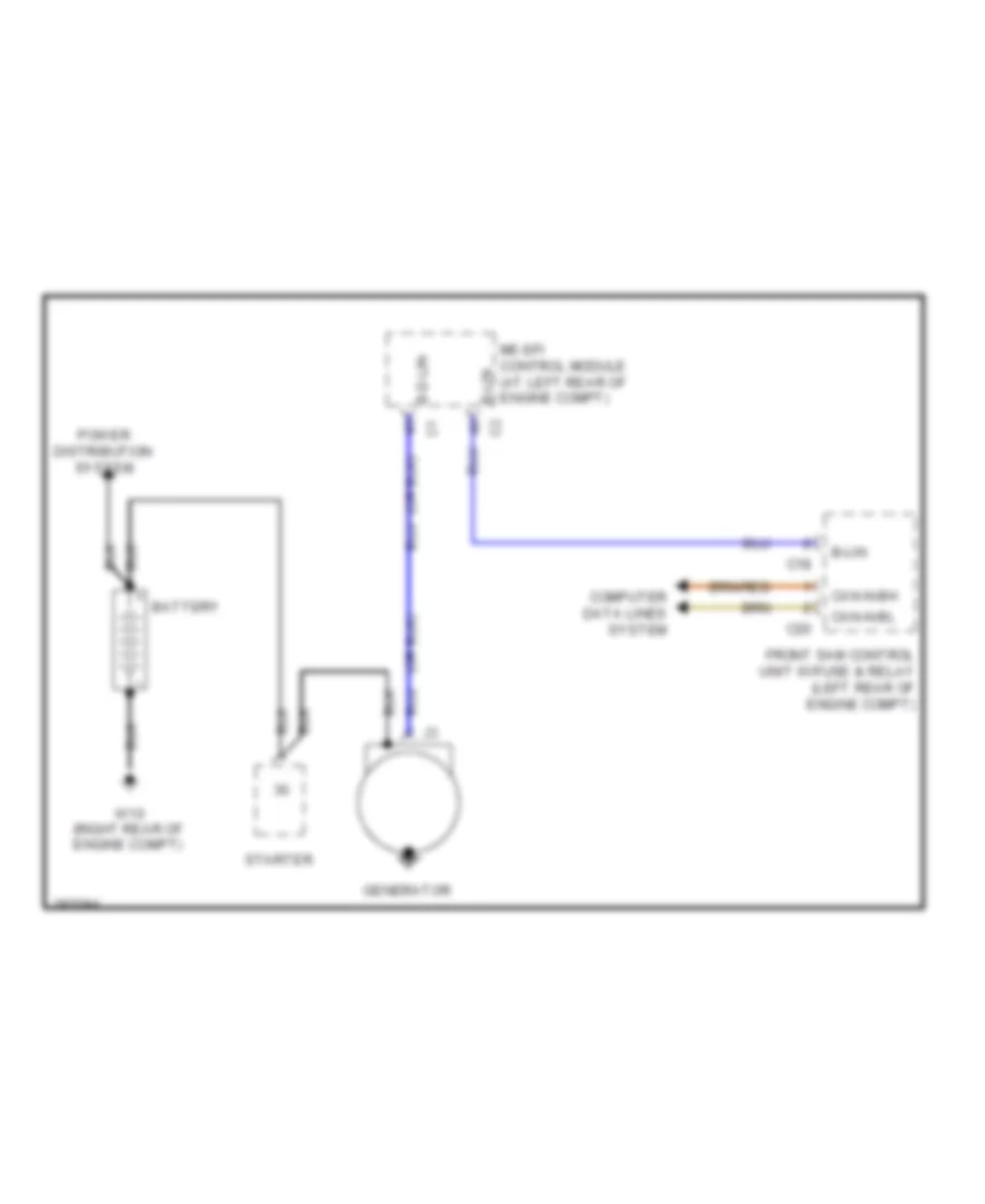
Charging Wiring Diagram for Mercedes-Benz C280 2006
List of elements for Charging Wiring Diagram for Mercedes-Benz C280 2006:
- B-d-lin
- B-lin
- Battery
- C18
- C20
- Can-n-bh
- Can-n-bl
- Computer data lines system
- Front sam control unit w/fuse & relay (left rear of engine compt)
- Generator
- Me-sfi control module (at left rear of engine compt)
- Power distribution system
- Starter
- W10 (right rear of engine compt)
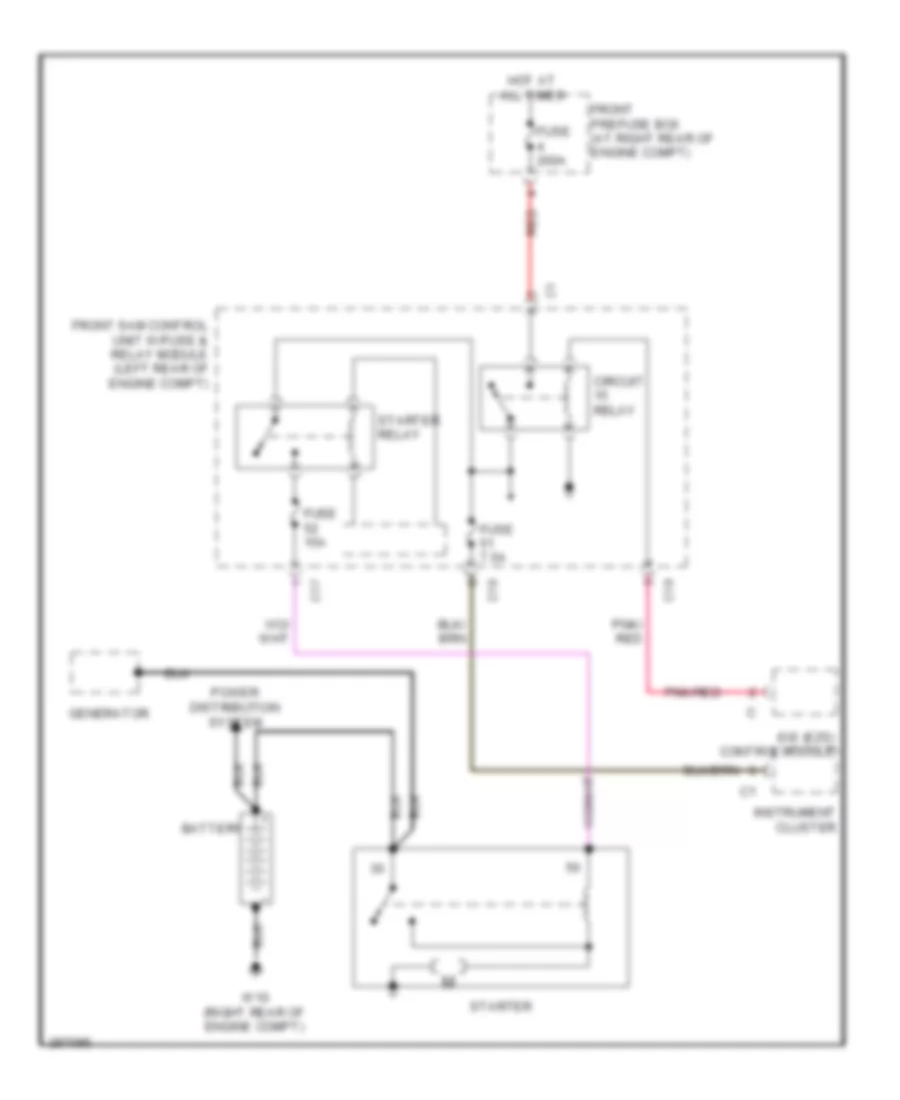
Starting Wiring Diagram for Mercedes-Benz C280 2006
List of elements for Starting Wiring Diagram for Mercedes-Benz C280 2006:
- Battery
- C17
- C19
- Circuit relay
- Eis (ezs) control module
- Front prefuse box (at right rear of engine compt)
- Front sam control unit w/fuse & relay module (left rear of engine compt)
- Fuse 15a
- Fuse 200a
- Fuse 7.5a
- Generator
- Hot at all times
- Instrument cluster
- Pnk/ red
- Pnk/red
- Power distribution system
- Red
- Starter
- Starter relay
- W10 (right rear of engine compt)
SUPPLEMENTAL RESTRAINTS
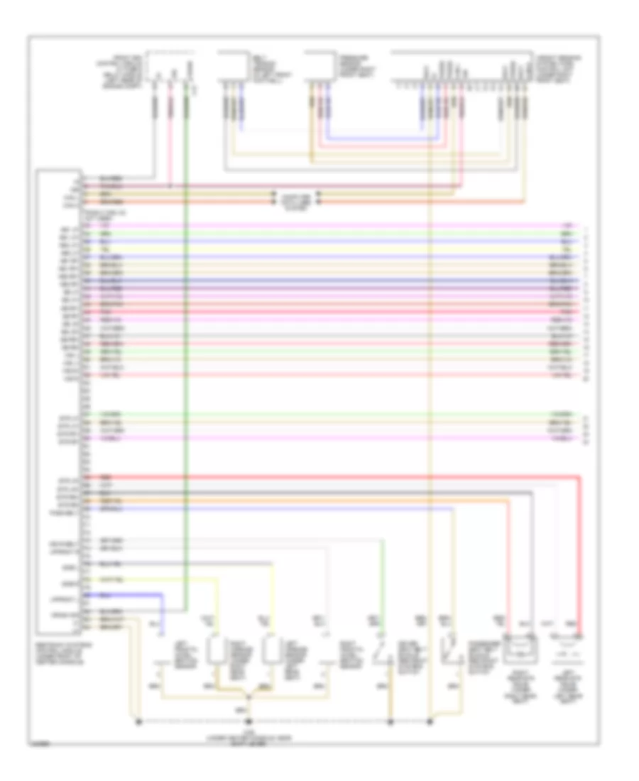
Supplemental Restraints Wiring Diagram (1 of 2) for Mercedes-Benz C280 2006
List of elements for Supplemental Restraints Wiring Diagram (1 of 2) for Mercedes-Benz C280 2006:
- (pins 5 thru 32: not used)
- 15r
- Ab1 lf+
- Ab1 lf-
- Ab1 rf+
- Ab1 rf-
- Ab2 lf+
- Ab2 lf-
- Ab2 rf+
- Ab2 rf-
- Belt
- Belt tension sensor (in left front footwell)
- C12
- Can h
- Can l
- Computer data lines system
- Crash
- Crash sig
- Driver seat belt buckle restraint systems switch
- Drvr belt
- Etr lf+
- Etr lf-
- Etr lr+
- Etr lr-
- Etr rf+
- Etr rf-
- Etr rr+
- Etr rr-
- Front sam control module w/ fuse & relay module (left rear of engine compt)
- Left airbags sensor (under left rear seat)
- Left frontal accel- eration sensor
- Left rear etr squib (under left rear seat)
- Pass belt
- Passenger seat belt buckle restraint systems switch
- Pnk
- Press
- Pressure sensor (under right front seat)
- Red
- Restraint systems control module (under front of center console)
- Right airbags sensor (under right rear seat)
- Right frontal accel- eration sensor
- Right rear etr squib (under right rear seat)
- Sb lf+
- Sb lf-
- Sb lr+
- Sb lr-
- Sb rf+
- Sb rf-
- Sb rr+
- Sb rr-
- Side l
- Side r
- Upfront l
- Upfront r
- W26 (under center console, near shift lever)
- Wb l+
- Wb l-
- Wb r+
- Wb r-
- Weight sensing system (wss) control unit (under right front seat)
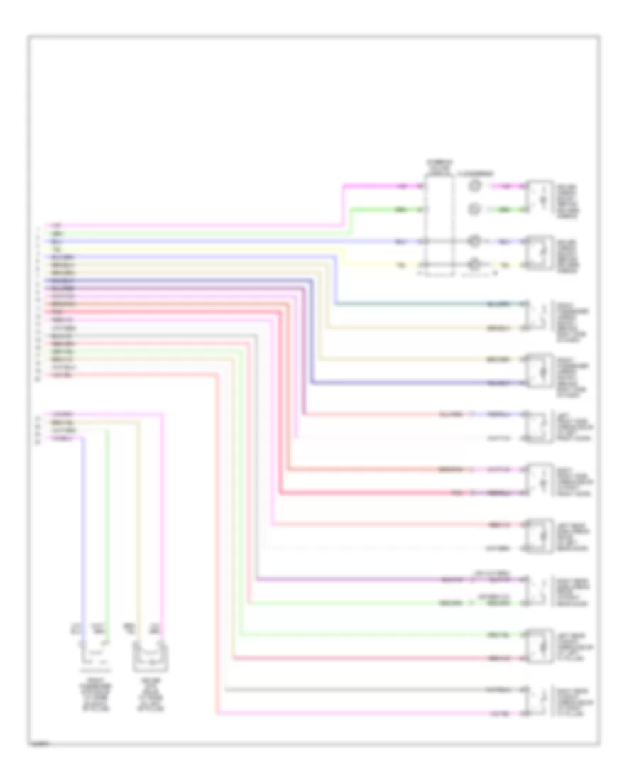
Supplemental Restraints Wiring Diagram (2 of 2) for Mercedes-Benz C280 2006
List of elements for Supplemental Restraints Wiring Diagram (2 of 2) for Mercedes-Benz C280 2006:
- Clockspring
- Driver airbag squib 1 (behind drivers airbag)
- Driver airbag squib 2 (behind drivers airbag)
- Driver etr squib (at base of left "b" pillar)
- Front passenger airbag squib 1 (behind right side of dash)
- Front passenger airbag squib 2 (behind right side of dash)
- Front passenger etr squib (at base of right "b" pillar)
- Left front side airbag squib (in left front door)
- Left rear side airbag squib (in left rear door)
- Left rear window airbag squib (at left "c" pillar)
- Pnk
- Right front side airbag squib (in right front door)
- Right rear side airbag squib (in right rear door)
- Right rear window airbag squib (at right "c" pillar)
- Steering column module
TRANSMISSION
Transmission Wiring Diagram, 5 Speed A/T for Mercedes-Benz C280 2006
List of elements for Transmission Wiring Diagram, 5 Speed A/T for Mercedes-Benz C280 2006:
- 1-2/ 4-5 valve
- 1-2/4-5 vlv
- 2-3 shift valve
- 2-3 vlv
- 3-4 shift valve
- 3-4 vlv
- C10
- C22
- Can-b h
- Can-b l
- Can-c h
- Can-c l
- Computer data lines system
- Electric control unit
- Electronic selector lever module control module (at base of gear shift assembly)
- Etc (egs) control module (under right side of dash)
- Front sam control unit w/ fuse & relay module (left rear of engine compt)
- Gear
- Gear display sensor (next to gear lever)
- Illum
- Kickdn
- Kickdown switch (incorporated into accelerator pedal assembly)
- Lock up valve
- Mode
- Modul- ator valve
- Modulator vlv
- Pins 1 thru 28: not used
- Pnk
- Pwm vlv
- Rpm 2
- Rpm 3
- Rpm sensor
- Sensor ground
- Sensor v+
- Shift valve
- Shift vlv
- Start interlock switch
- Temp sensor
- Temp/start
- Transmission mode switch
- W18 (under driver's seat)
Transmission Wiring Diagram, 7 Speed A/T for Mercedes-Benz C280 2006
List of elements for Transmission Wiring Diagram, 7 Speed A/T for Mercedes-Benz C280 2006:
- B1 brake valve
- B2 brake valve
- B3 brake valve
- C10
- C22
- Can-b h
- Can-b l
- Can-c h
- Can-c l
- Computer data lines system
- Electric control unit (vgs)
- Electronic selector lever module control module (at base of gear shift assembly)
- Front sam control unit w/ fuse & relay module (left rear of engine compt)
- Fuse 7.5a
- Gear
- Gear display sensor (next to gear lever)
- Gnd
- Hot w/ circuit 87 relay energised
- Illum
- Internal speed sensor
- K1 clutch valve
- K2 clutch valve
- K3 clutch valve
- Kickdn
- Kickdown switch (incorporated into accelerator pedal assembly)
- Lockup valve
- Mode
- Output speed sensor
- Pnk
- Range sensor
- Temp sensor
- Transmission mode switch
- Turbine speed sensor
- W18 (under driver's seat)
- Working pressure valve
TRUNK, TAILGATE, FUEL DOOR
Trunk, Tailgate, Fuel Door Wiring Diagram for Mercedes-Benz C280 2006
List of elements for Trunk, Tailgate, Fuel Door Wiring Diagram for Mercedes-Benz C280 2006:
- (at rear of trunk lid)
- (coupe)
- (left rear of engine compt) front sam control module w/ fuse & relay module
- (left side of trunk, near rear sam) w55
- (sedan & wagon)
- C10
- C13
- C21
- Can h
- Can l
- Can-b h
- Can-b l
- Computer data lines system
- Front pre-fuse box (right rear of engine compt)
- Fuse 200a
- Hot at all times
- Nca
- Pnk/red
- Rear sam control module w/ fuse & relay module (left side of trunk/cargo area)
- Red
- Trunk ajar
- Trunk emerg
- Trunk ext
- Trunk lid central locking motor (in center rear of trunk lid)
- Trunk lid contact switch (at center rear of trunk lid)
- Trunk lid emergency release switch
- Trunk lid external operation switch (in trunk lid)
- Trunk motor
- W16/3 (left rear of engine compt)
- W6 (left side of trunk)
WARNING SYSTEMS
Warning Systems Wiring Diagram for Mercedes-Benz C280 2006
List of elements for Warning Systems Wiring Diagram for Mercedes-Benz C280 2006:
- 2.5l & 3.0l
- 3.5l
- Bk wear
- Brake fluid & parking brake warning lamp
- Brake fluid indicator switch (in brake fluid reservoir)
- Brk fluid
- C19
- Can b h
- Can b l
- Can c h
- Can c l
- Compt)
- Computer data lines system
- Driver seat belt buckle restraint systems switch
- Drvr belt
- Esp & bas control module (at left front of engine compt)
- Front sam control unit w/ fuse & relay module (left rear of engine c6
- Fuse 7.5a
- Hot at all times
- Hot in run or start
- Instrument cluster
- Interior fuse box (left end of dash)
- Multifunction display
- Nca
- Parking brake indicator switch (on parking brake support bracket)
- Prk brk
- Restraint system control module (under front of center console)
- Right front brake pad contact sensor (at right front wheel)
- Right rear brake pad contact sensor (at right rear wheel)
- Seat belt reminder lamp
- W16/3 (left rear of engine compt)
- W26 (under center console, near shift lever)
- W28/2
- Warning buzzer
WIPER/WASHER
Headlamp Washer Wiring Diagram for Mercedes-Benz C280 2006
List of elements for Headlamp Washer Wiring Diagram for Mercedes-Benz C280 2006:
- 30z
- C15
- C20
- Can-b h
- Can-b l
- Computer data lines system
- Front pre-fuse box (at right rear of engine compt)
- Front sam control unit w/ fuse & relay module (left rear of engine compt)
- Fuse 200a
- Fuse 60a
- Hcs pump (in left wheelwell, on washer fluid reservoir)
- Headlamp cleaning system (hcs) switch
- Hot at all times
- Lamp switch module
- Red
- Sra
- W16/3 (left rear of engine compt)
- W9 (behind left headlight)
Wiper/Washer Wiring Diagram, Sedan & Coupe for Mercedes-Benz C280 2006
List of elements for Wiper/Washer Wiring Diagram, Sedan & Coupe for Mercedes-Benz C280 2006:
- 15r
- 30z
- C10
- C13
- C16
- C19
- C22
- Can-b h
- Can-b l
- Can-c h
- Can-c l
- Combination switch
- Computer data lines system
- Coolant level indicator switch (right front of engine compt)
- Di control module
- Esp & bas control module (at left front of engine compt)
- Front pre-fuse box (at right rear of engine compt)
- Front sam control unit w/ fuse & relay module (left rear of engine compt)
- Fuse 200a
- Fuse 20a
- Fuse 60a
- Hot at all times
- Interior fuse box (left end of dash)
- Motor
- Nca
- Overhead control panel control module
- Pnk/red
- Rain/light sensor (at front of headliner)
- Rear sam control unit w/ fuse & relay module (left side of trunk/cargo area)
- Red
- Relay
- Ss lf
- Ss lr
- Ss rf
- Ss rr
- Steering column module (at top of steering column)
- To wheel speed sensors
- W16/3 (left rear of engine compt)
- W28/1 (under left front door sill)
- W28/2
- W6 (left side of trunk)
- W9 (behind left headlight)
- Washer nozzle heaters
- Washer nozzle hose heater
- Windshield washer fluid level indicator switch (in left front wheelwell, in washer bottle)
- Windshield washer fluid pump (in left front wheelwell, on washer fluid reservoir)
- Windshield washer system switch
- Wiper motor (at left rear of engine compt)
- Wiper on/off relay
- Wiper switch

 Čeština
 Dansk
Dansk Deutsch
 Ελληνικά
 English
 English
 Español
 Suomi
Suomi Français
 Français
 עברית
עברית Hrvatski
 Magyar
 Italiano
 日本語
日本語 한국어
한국어 Nederlands
 Polski
 Português
 Português
 Română
 Русский
 Slovenščina
 Svenska
 Türkçe
 中文 (中国)