AIR CONDITIONING
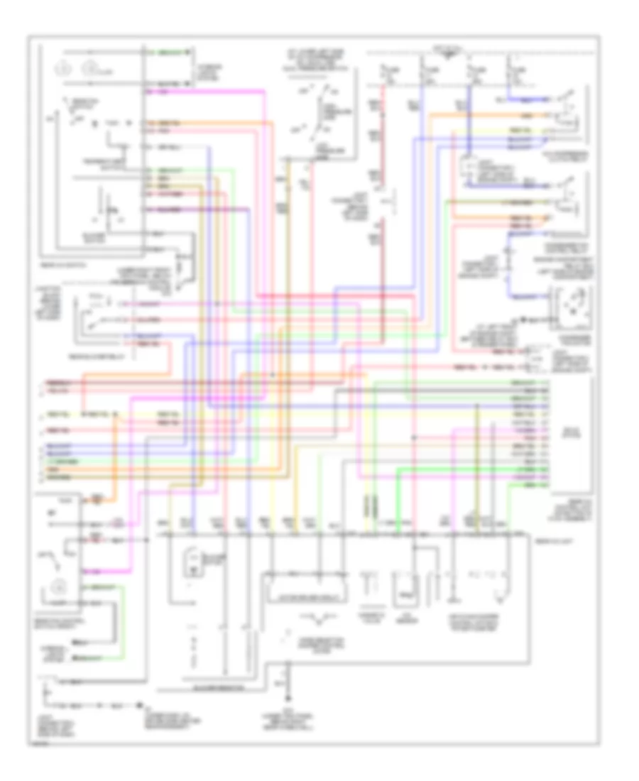
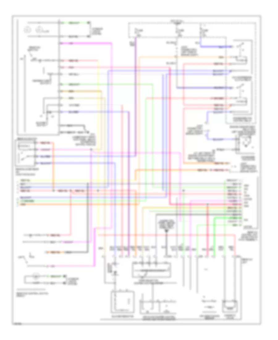
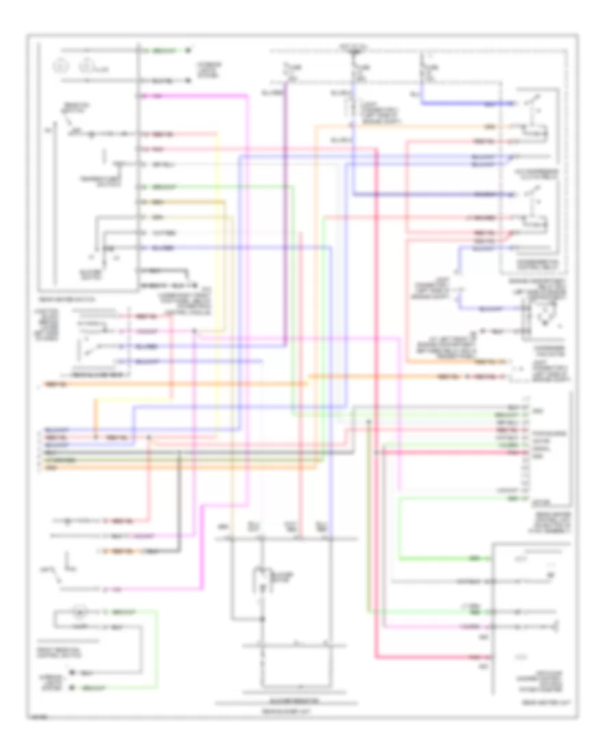
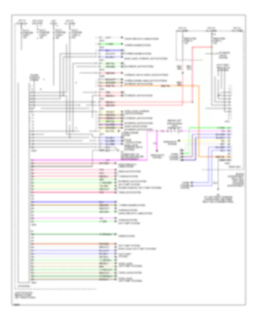
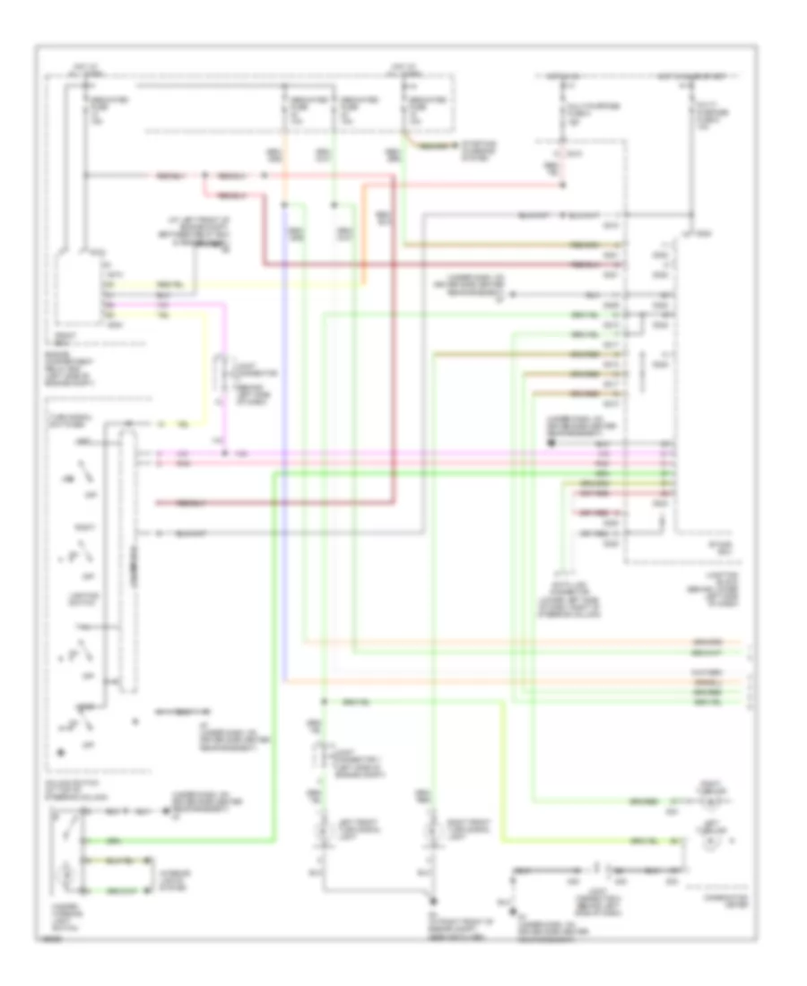
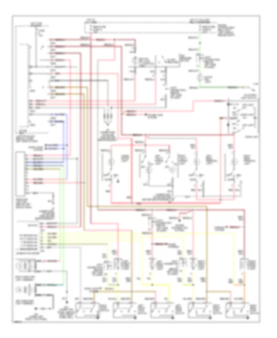
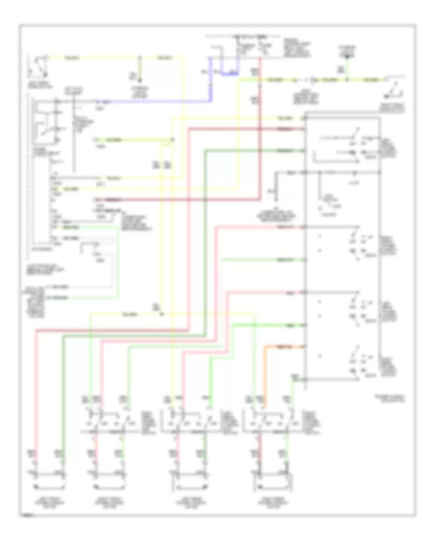
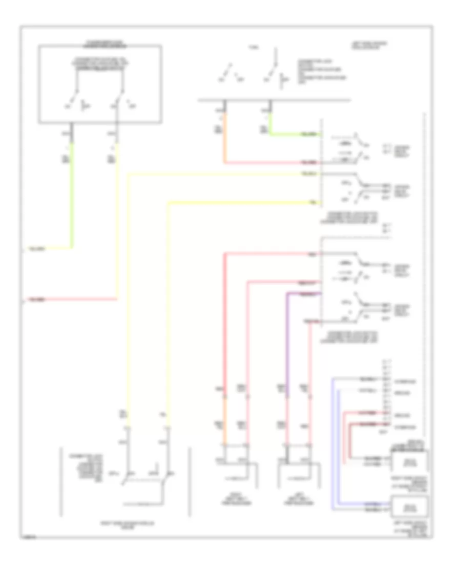
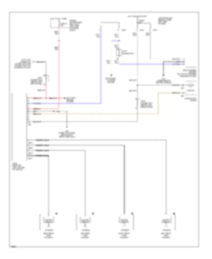
Automatic A/C Wiring Diagram, with Rear A/C (1 of 2) for Mitsubishi Montero Limited 2004
 https://portal-diagnostov.com/license.html
Automotive Electricians Portal FZCO
Automotive Electricians Portal FZCO
https://portal-diagnostov.com/license.html
https://portal-diagnostov.com/license.html
Automotive Electricians Portal FZCO
Automotive Electricians Portal FZCO
List of elements for Automatic A/C Wiring Diagram, with Rear A/C (1 of 2) for Mitsubishi Montero Limited 2004:
- (behind center of dash) mode selection damper control motor & potentiometer
- A/c compressor
- A/c compressor clutch
- A/c ecu (behind center of dash)
- Air conditioning sensor (at right side of cargo area, on rear a/c unit or rear cooler unit)
- Air mixing damper control motor & potentiometer (below center of dash)
- Ambient air temperature sensor (right front of vehicle)
- Blower motor (below right side of dash)
- D08
- D132
- D134
- D135
- D208
- D209
- D210
- D220
- D23
- D24
- Data link connector (lower left side
- Defogger system
- Engine compartment relay box (left side of engine compt)
- Engine controls system
- Engine coolant temperature sensor (on rear of cylinder head)
- Front blower relay
- Fuse 10a
- Fuse 30a
- G7 (under dash, on driver side center reinforcement)
- G8 (under dash, on passenger side reinforcement)
- Heater blower controller unit (on hvac assembly)
- Heater water temperature sensor (on hvac assembly)
- Hot at all times
- Hot in on
- Hot in on or acc
- Interior lights system
- Joint connector 5 (behind left end of dash)
- Joint connector 6 (behind left side of dash)
- Joint connector 8 (behind left side of dash)
- Junction block (behind lower left side of dash)
- Lock sensor
- Of dash, right of steering column)
- Outside/ inside air selection damper control motor (below right side of dash)
- Photo sensor (on top center of dash)
- Pnk
- Powertrain control module (behind lower right side of dash)
- Red
- Rv meter
- Solid state
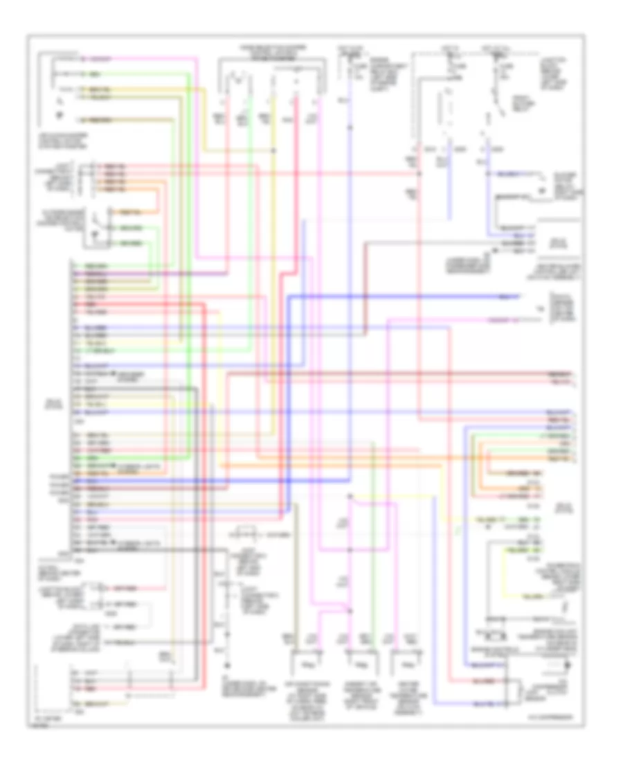
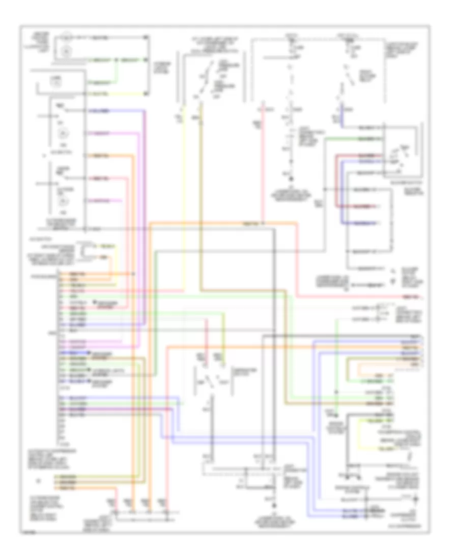
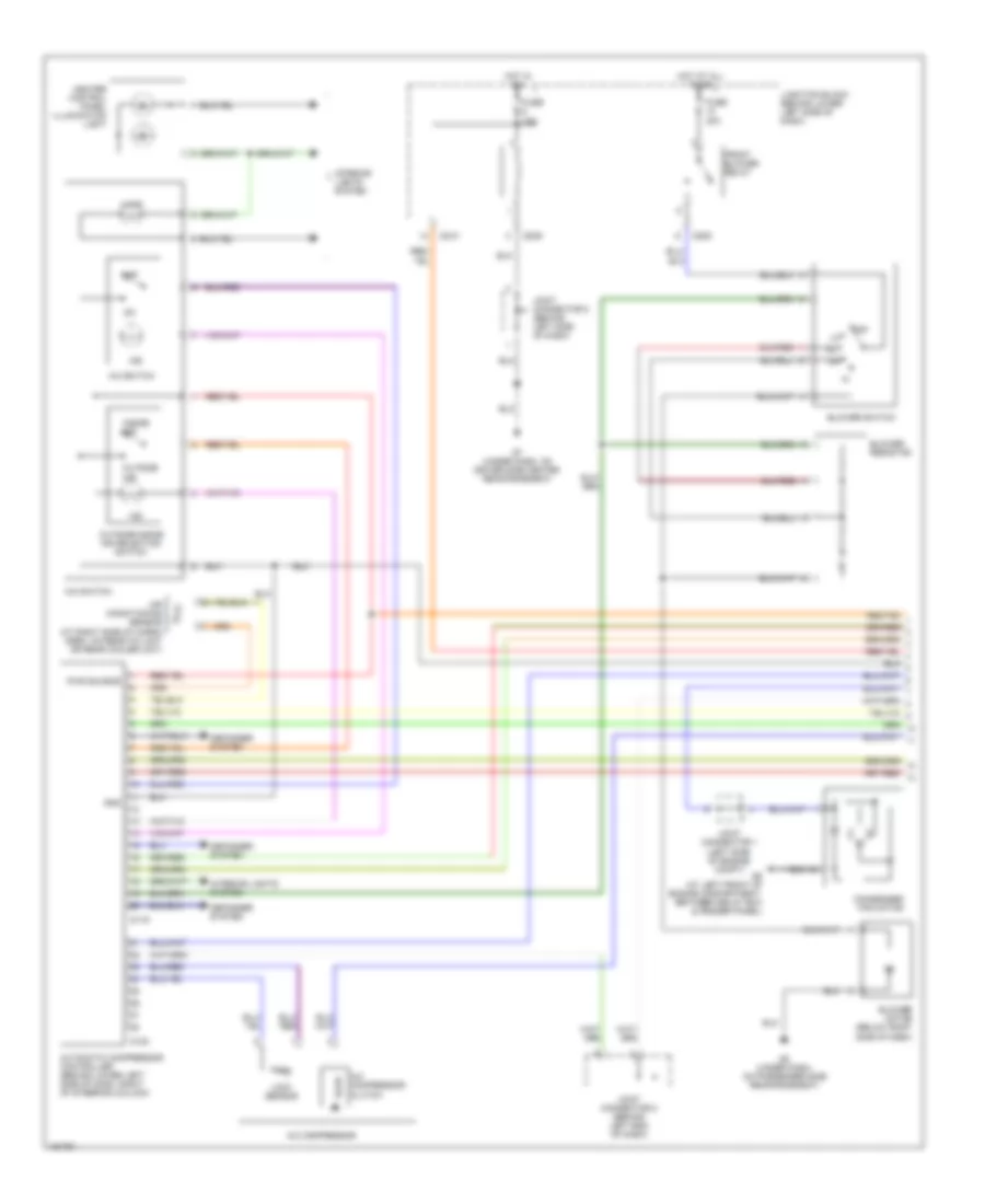
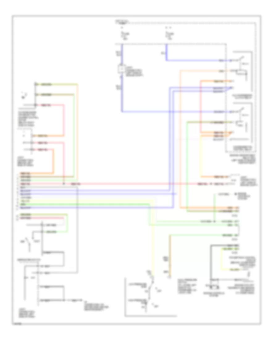
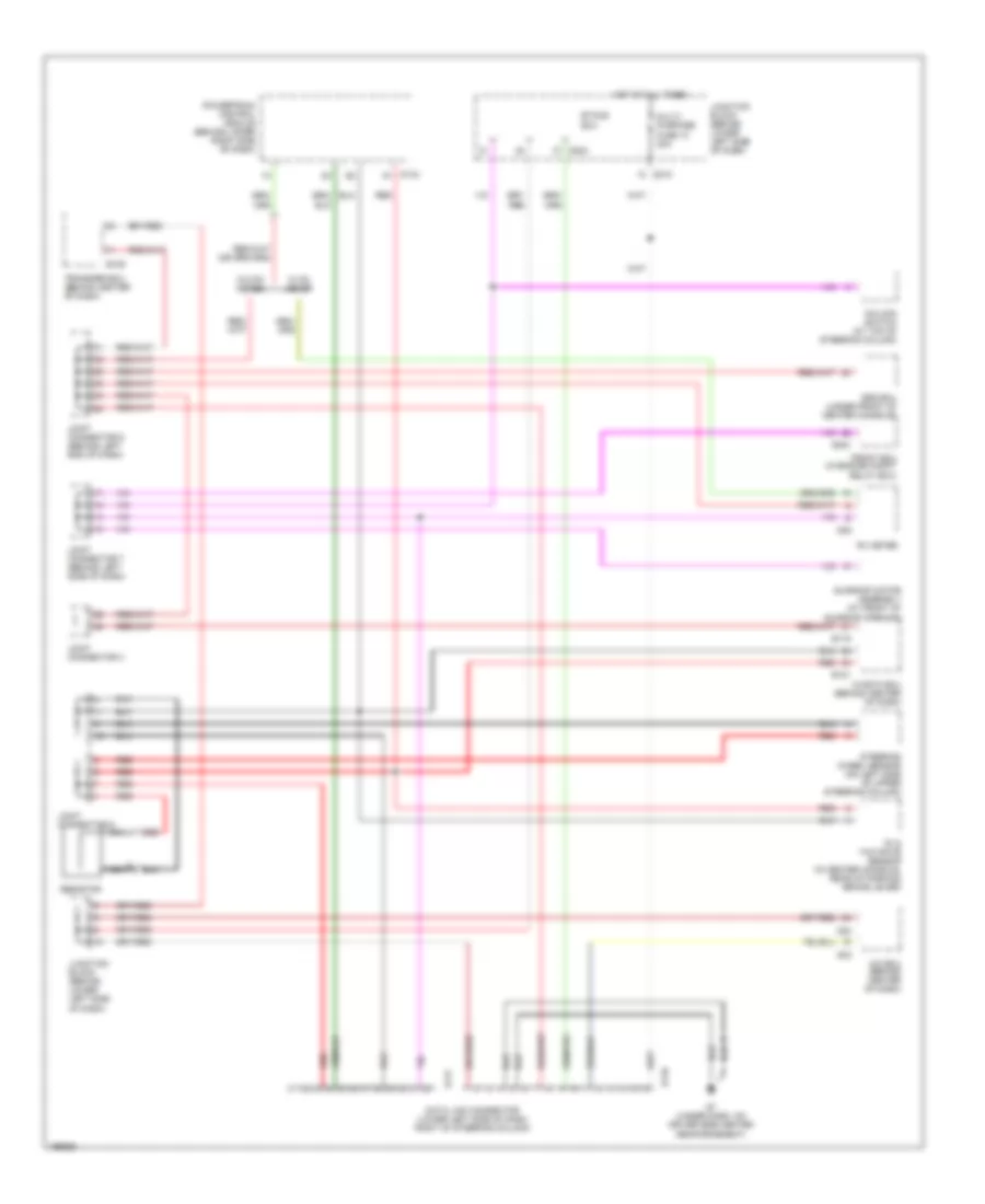
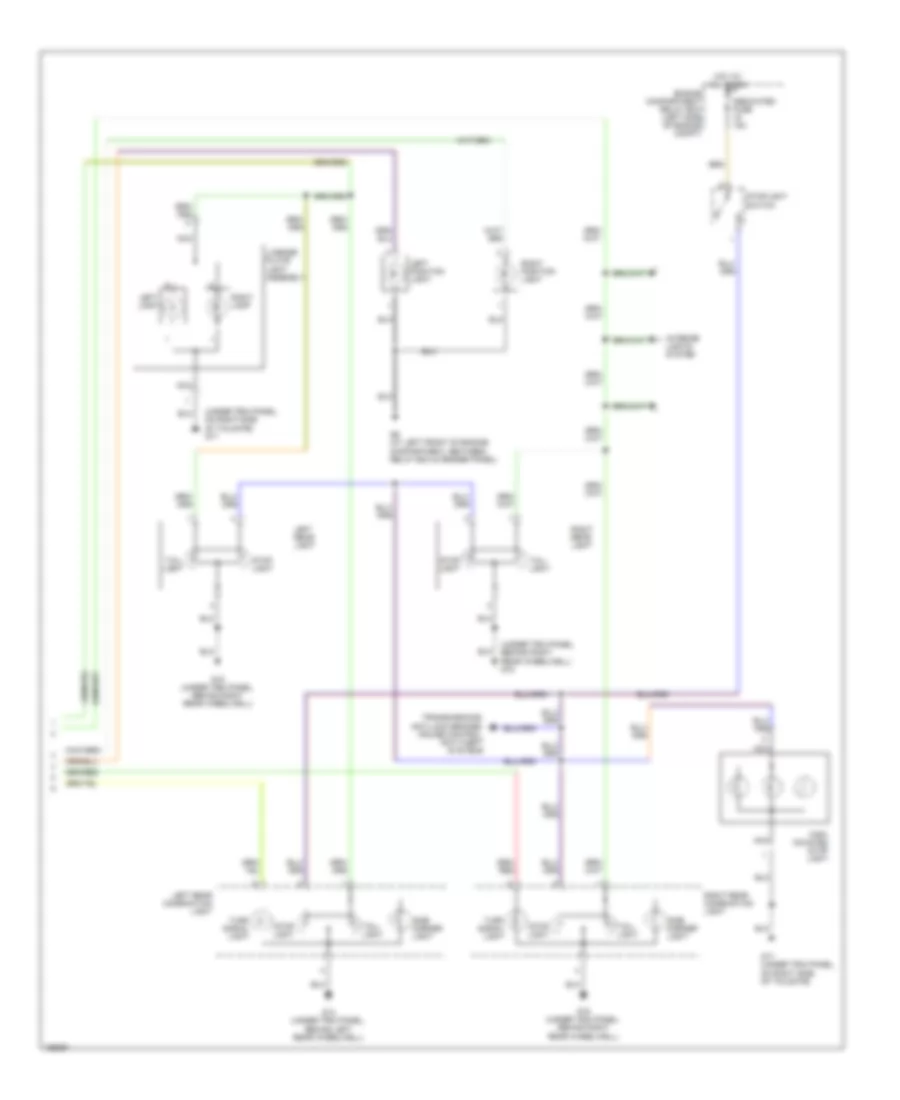
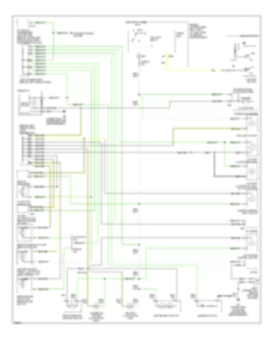
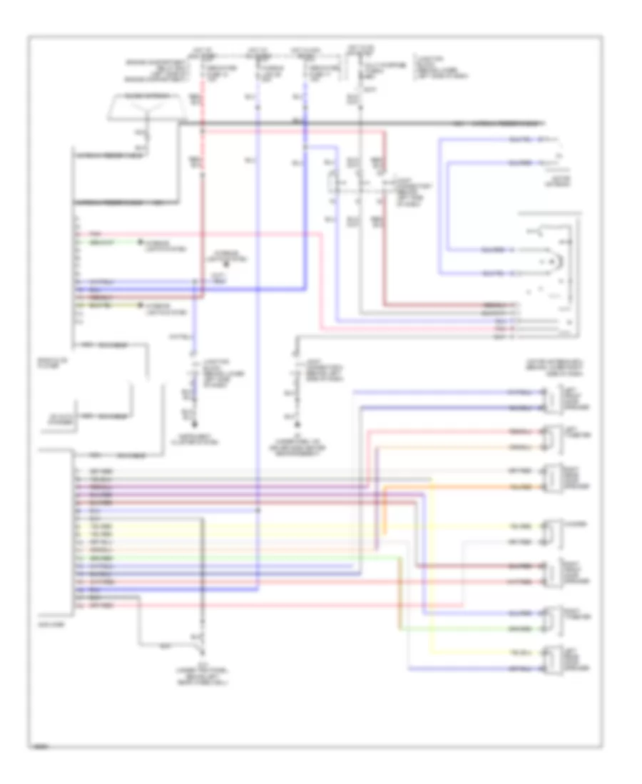
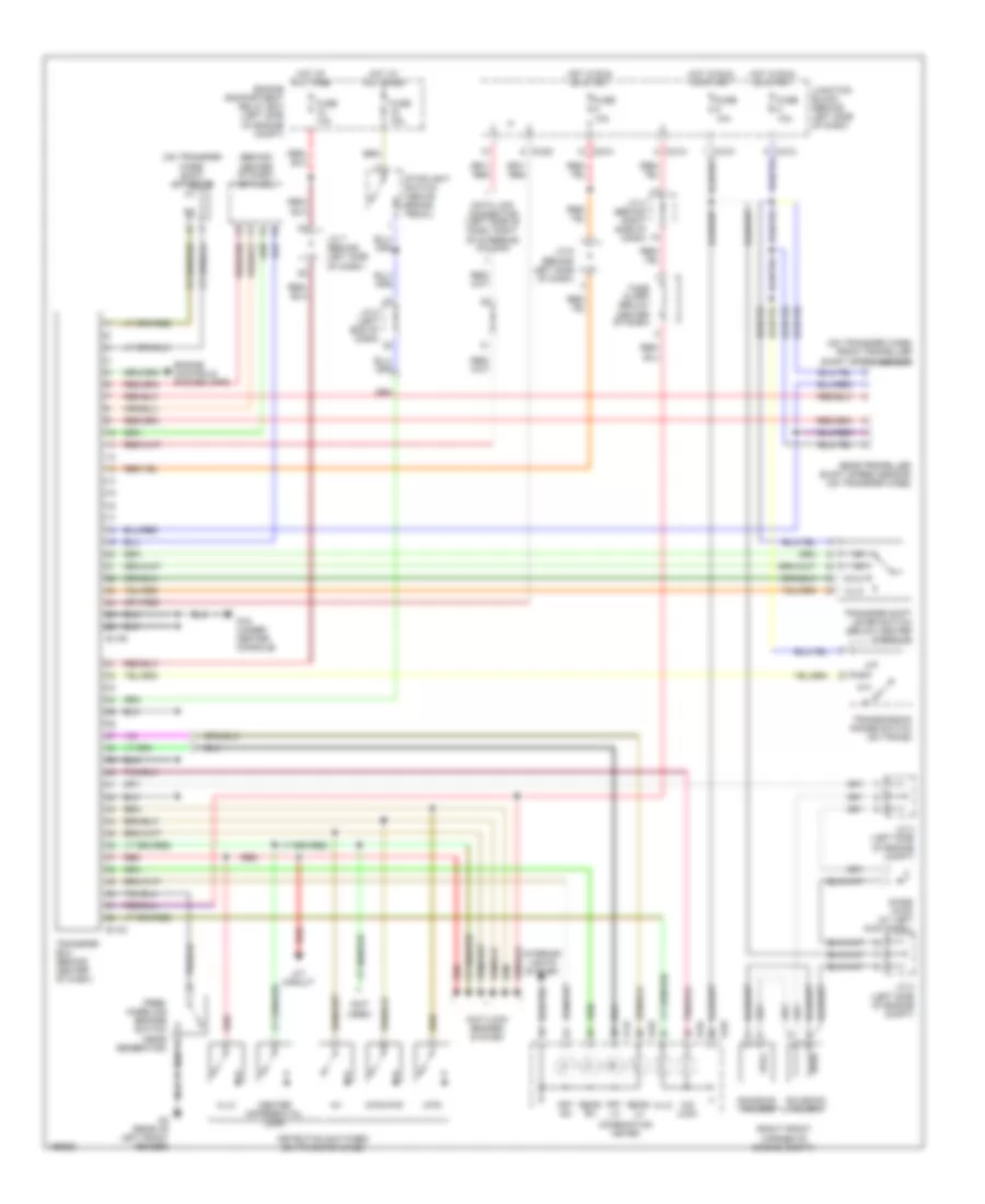
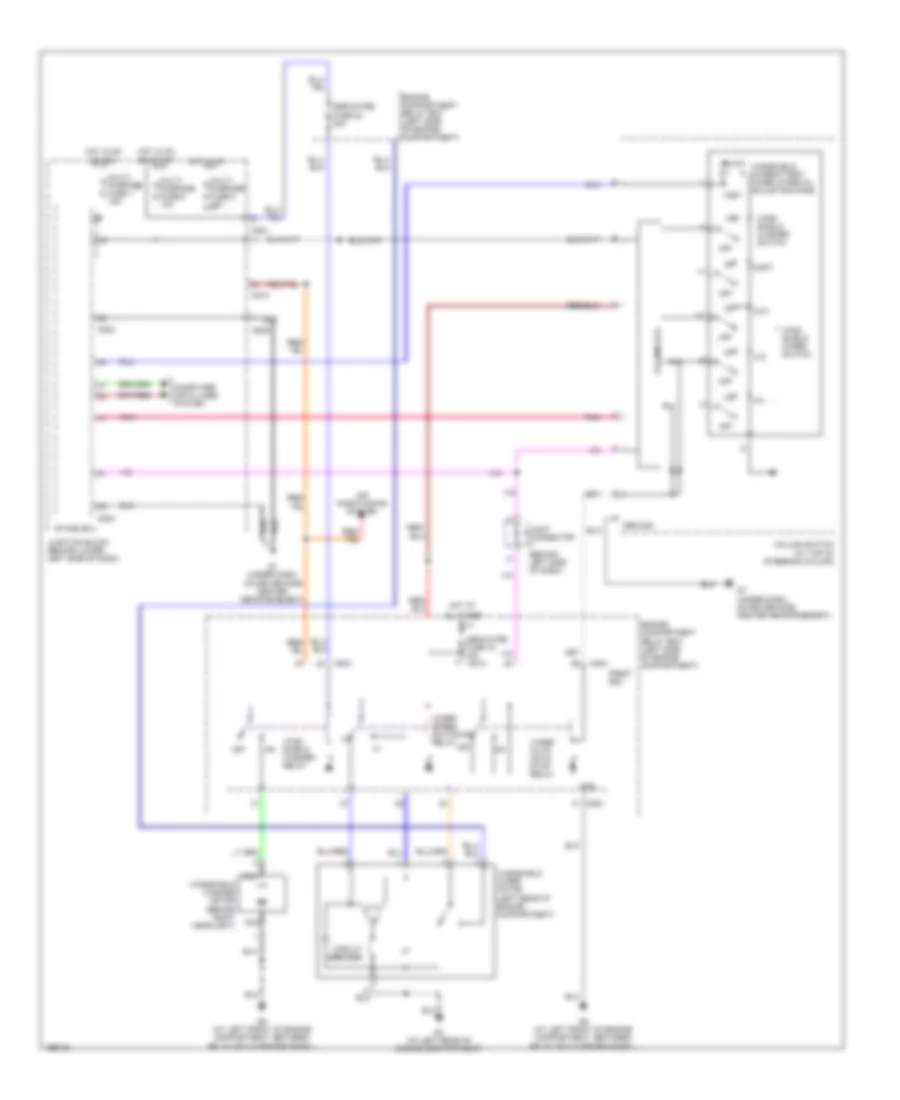
Automatic A/C Wiring Diagram, with Rear A/C (2 of 2) for Mitsubishi Montero Limited 2004
List of elements for Automatic A/C Wiring Diagram, with Rear A/C (2 of 2) for Mitsubishi Montero Limited 2004:
- (at lower left side of a/c compressor, on liquid line) dual pressure switch
- (under right front kick panel, below powertrain control module) g12
- A/c compressor clutch relay
- A/c sensor
- Air mixing damper control motor & potentiometer
- Blower motor
- Blower resistor
- Blower switch
- Condenser fan control relay
- Condenser fan motor
- Engine compartment relay box (left side of engine compartment)
- Fuse 10a
- Fuse 15a
- Fuse 20a
- Fuse 25a
- G15 (under trim panel, behind right rear wheelwell)
- G22
- G24
- G26
- G6 (at left front of engine compt, between relay box & fender panel)
- G7 (under dash, on driver side center reinforcement)
- High- pressure side
- Hot at all times
- Illum
- Interior lights system
- Joint connector 1 (left side of engine compt)
- Joint connector 2 (left side of engine compt)
- Joint connector 3 (left side of engine compt)
- Joint connector 7 (behind left side of dash)
- Joint connector 8 (behind left side of dash)
- Junction block (behind lower left side of dash)
- Low- pressure side
- Magnetic valve
- Mode selection damper control motor
- Motor driver circuit
- Off
- Pnk
- Rear a/c control unit (on bottom of hvac assembly)
- Rear a/c switch
- Rear a/c unit
- Rear blower relay
- Rear fan control switch (front)
- Rear fan switch
- Solid state
- Temperature switch
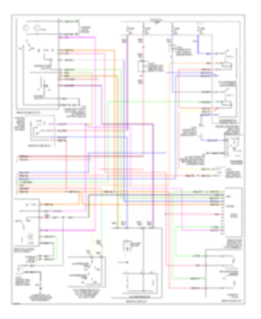
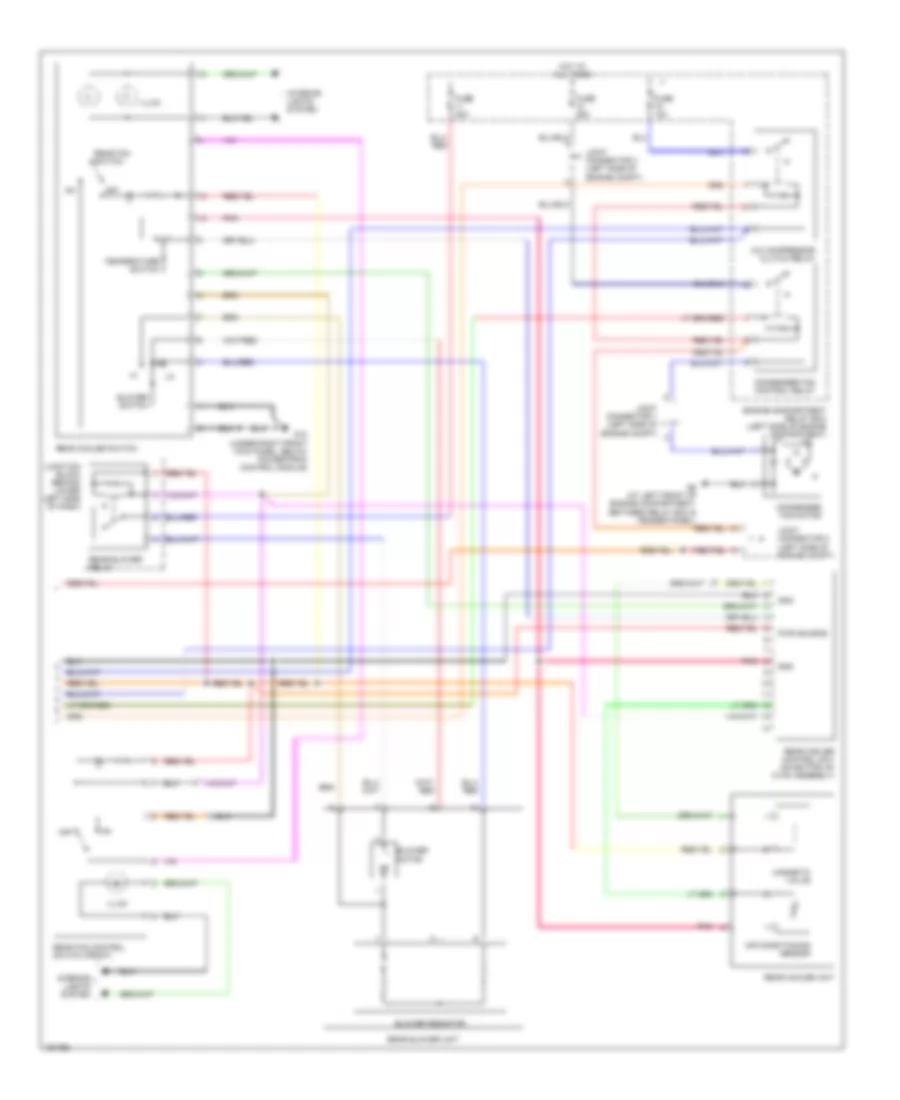
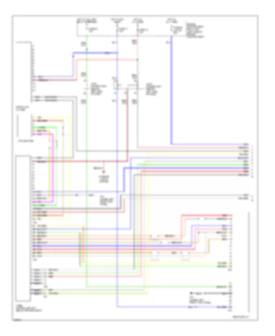
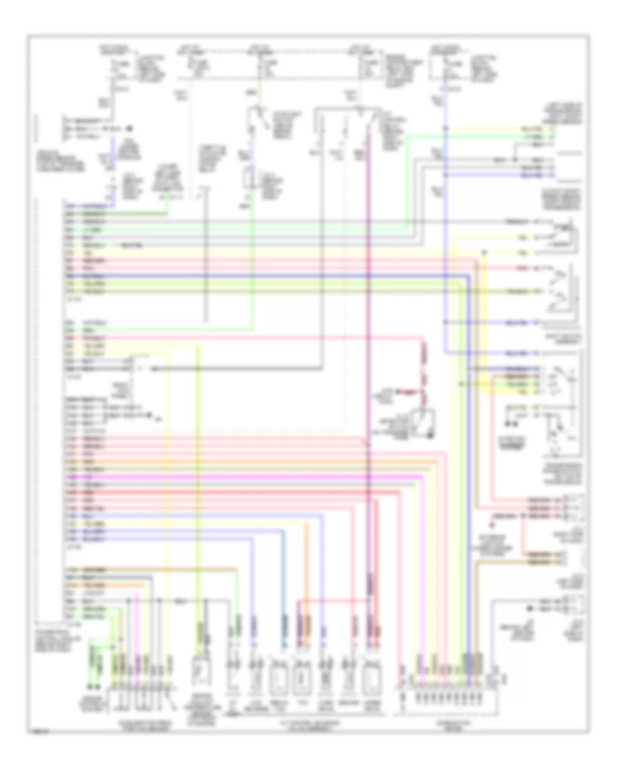
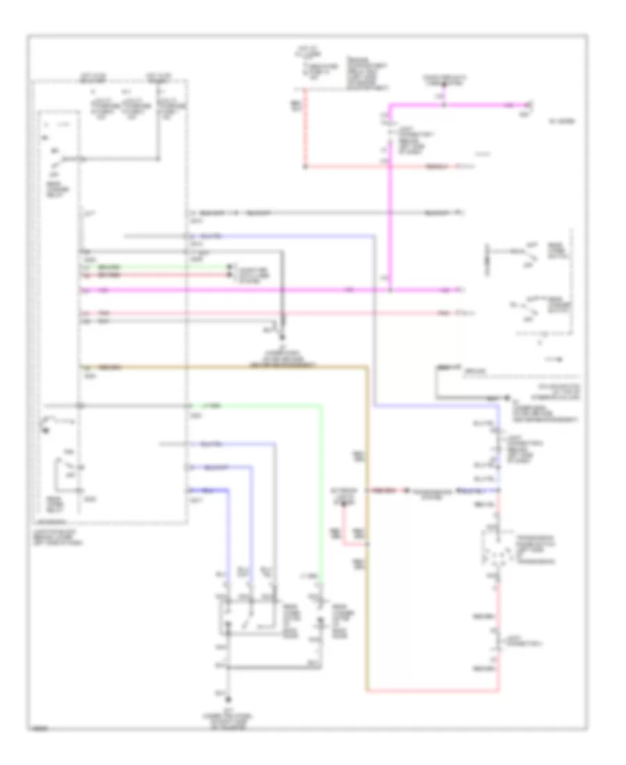
Automatic A/C Wiring Diagram, with Rear Cooler (1 of 2) for Mitsubishi Montero Limited 2004
List of elements for Automatic A/C Wiring Diagram, with Rear Cooler (1 of 2) for Mitsubishi Montero Limited 2004:
- A/c compressor
- A/c compressor clutch
- A/c ecu (behind center of dash)
- Air conditioning sensor (at right side of cargo area, on rear a/c unit or rear cooler unit)
- Air mixing damper control motor & potentiometer
- Ambient air temperature sensor (right front of vehicle)
- Blower motor (below right side of dash)
- Connector (lower left side of dash, right of steering column)
- D08
- D132
- D134
- D135
- D208
- D209
- D210
- D220
- D23
- D24
- Data link
- Defogger system
- Engine compartment relay box (left side of engine compt)
- Engine controls system
- Engine coolant temperature sensor (on rear of cylinder head)
- Front blower relay
- Fuse 10a
- Fuse 30a
- G7 (under dash, on driver side center reinforcement)
- G8 (under dash, on passenger side reinforcement)
- Gnd
- Heater blower controller unit (on hvac assembly)
- Heater water temperature sensor (on hvac assembly)
- Hot at all times
- Hot in on
- Hot in on or acc
- Interior lights system
- Joint connector 5 (behind left end of dash)
- Joint connector 6 (behind left side of dash)
- Joint connector 8 (behind left side of dash)
- Junction block (behind lower left side of dash)
- Lock sensor
- Mode selection damper control motor & potentiometer
- Outside/inside air selection damper control motor
- Photo sensor (on top center of dash)
- Pnk
- Power
- Powertrain control module (behind lower right side of dash)
- Red
- Rv meter
- Solid state
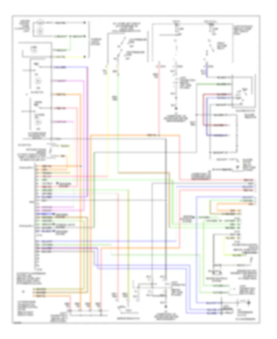
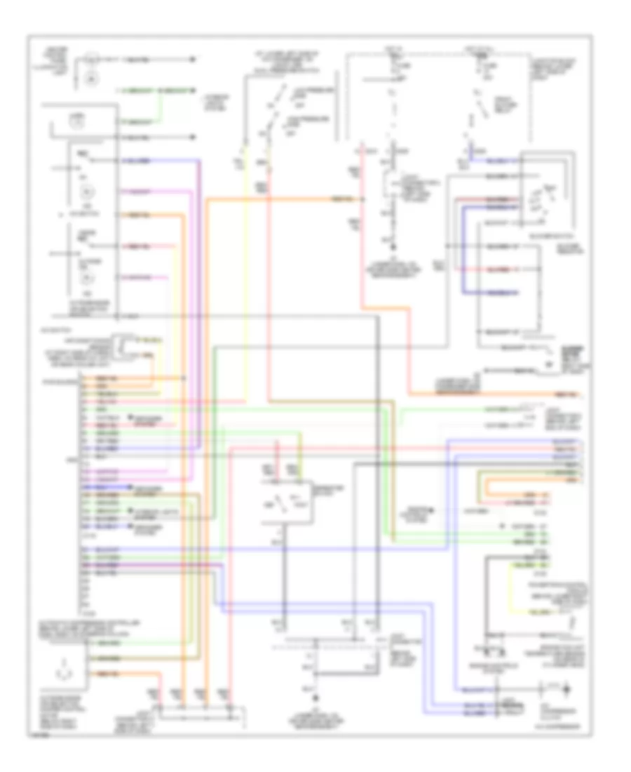
Automatic A/C Wiring Diagram, with Rear Cooler (2 of 2) for Mitsubishi Montero Limited 2004
List of elements for Automatic A/C Wiring Diagram, with Rear Cooler (2 of 2) for Mitsubishi Montero Limited 2004:
- (under right front kick panel, below powertrain control module)
- A/c compressor clutch relay
- Air conditioning sensor
- Blower motor
- Blower resistor
- Blower switch
- Condenser fan control relay
- Condenser fan motor
- Dual pressure switch (at lower left side of a/c condenser, on liquid line)
- Engine compartment relay box (left side of engine compt)
- Fuse 10a
- Fuse 15a
- Fuse 20a
- Fuse 25a
- G12
- G6 (at left front of engine compartment, between relay box & fender panel)
- G7 (under dash, on driver side center reinforcement)
- Gnd
- High-pressure side
- Hot at all times
- Illum
- Interior lights system
- Joint connector 1 (left side of engine compt)
- Joint connector 2 (left side of engine compt)
- Joint connector 3 (left side of engine compt)
- Joint connector 7 (behind left side of dash)
- Joint connector 8 (behind left side of dash)
- Junction block (behind lower left side of dash)
- Low-pressure side
- Magnetic valve
- Off
- Pnk
- Power
- Rear blower relay
- Rear blower unit
- Rear cooler control unit (on bottom of hvac assembly)
- Rear cooler switch
- Rear cooler unit
- Rear fan control switch (front)
- Solid state
- Temperature switch
Manual A/C Wiring Diagram, Dual A/C Wiring Diagram with Rear A/C (1 of 2) for Mitsubishi Montero Limited 2004
List of elements for Manual A/C Wiring Diagram, Dual A/C Wiring Diagram with Rear A/C (1 of 2) for Mitsubishi Montero Limited 2004:
- (at lower left side of a/c condenser, on liquid line) dual pressure switch
- A/c compressor
- A/c compressor clutch
- A/c switch
- Air conditioning sensor (at right side of cargo area, on rear a/c unit or rear cooler unit)
- Automatic compressor controller (behind lower left side of dash, right of steering column)
- Blower motor (below right side of dash)
- Blower resistor
- Blower switch
- D119
- D120
- D132
- D134
- D135
- D208
- D209
- D210
- Def
- Defogger system
- Defroster switch
- Engine controls system
- Engine coolant temperature sensor (on rear of cylinder head)
- Foot
- Front blower relay
- Fuse 10a
- Fuse 30a
- G7 (under dash, on driver side center reinforcement)
- G7 (under dash, on driver side center reinforcement)
- G8 (under dash, on passenger side reinforcement)
- Gnd
- Heater control panel illumination light
- High-pressure side
- Hot at all times
- Hot in on
- Illum
- Ind
- Inside air
- Interior lights system
- Joint connector (behind left side of dash)
- Joint connector 5 (behind left end of dash)
- Joint connector 6 (behind left side of dash)
- Joint connector 8 (behind left side of dash)
- Junction block (behind lower left side of dash)
- Lock sensor
- Low-pressure side
- Off
- Outside air
- Outside/inside air selection damper control motor (below right side of dash)
- Outside/inside air selection switch
- Powertrain control module (behind lower right side of dash)
Manual A/C Wiring Diagram, Dual A/C Wiring Diagram with Rear A/C (2 of 2) for Mitsubishi Montero Limited 2004
List of elements for Manual A/C Wiring Diagram, Dual A/C Wiring Diagram with Rear A/C (2 of 2) for Mitsubishi Montero Limited 2004:
- (under right front kick panel, below powertrain control module)
- (under trim panel, behind right rear wheelwell) g15
- A/c compressor clutch relay
- Air conditioning sensor
- Air mixing damper control motor and potentiometer
- Blower motor
- Blower resistor
- Blower switch
- Condenser fan control relay
- Condenser fan motor
- Engine compartment relay box (left side of engine compartment)
- Fuse 10a
- Fuse 20a
- Fuse 25a
- G12
- G22
- G24
- G26
- G6 (at left front of engine compartment, between relay box & fender panel)
- Gnd
- Hot at all times
- Illum
- Interior lights system
- Joint connector 1 (left side of engine compt)
- Joint connector 2 (left side of engine compt)
- Joint connector 3 (left side of engine compt)
- Magnetic valve
- Mode selection damper control motor
- Motor
- Motor drive circuit
- Off
- Pnk
- Pwr
- Rear a/c
- Rear a/c control unit (on bottom of hvac assembly)
- Rear a/c switch
- Rear blower rear (on junction block)
- Rear fan control switch (front)
- Rear fan switch
- Sig
- Temperature switch
- Unit
Manual A/C Wiring Diagram, Dual A/C Wiring Diagram with Rear Cooler (1 of 2) for Mitsubishi Montero Limited 2004
List of elements for Manual A/C Wiring Diagram, Dual A/C Wiring Diagram with Rear Cooler (1 of 2) for Mitsubishi Montero Limited 2004:
- (at lower left side of a/c condenser, on liquid line) dual pressure switch
- (behind left side of dash)
- (under dash, on passenger side reinforcement) g8
- A/c compressor
- A/c compressor clutch
- A/c switch
- Air conditioning sensor (at right side of cargo area, on rear a/c unit or rear cooler unit)
- Automatic compressor controller (behind lower left side of dash, right of steering column)
- Blower motor (below right side of dash)
- Blower resistor
- Blower switch
- D119
- D120
- D132
- D134
- D135
- D208
- D209
- D210
- Def
- Defogger system
- Defroster switch
- Engine controls system
- Engine coolant temperature sensor (on rear of cylinder head)
- Foot
- Front blower relay
- Fuse 10a
- Fuse 30a
- G7 (under dash, on driver side center reinforcement)
- Gnd
- Heater control panel illumination light
- High- pressure side
- Hot at all times
- Hot in on
- Illum
- Ind
- Inside air
- Interior lights system
- Joint connector
- Joint connector 5 (behind left end of dash)
- Joint connector 6 (behind left side of dash)
- Joint connector 8 (behind left side of dash)
- Junction block (behind lower left side of dash)
- Lock sensor
- Low- pressure side
- Off
- Outside air
- Outside/inside air selection damper control motor (below right side of dash)
- Outside/inside air selection switch
- Powertrain control module (behind lower right side of dash)
- Pwr source
Manual A/C Wiring Diagram, Dual A/C Wiring Diagram with Rear Cooler (2 of 2) for Mitsubishi Montero Limited 2004
List of elements for Manual A/C Wiring Diagram, Dual A/C Wiring Diagram with Rear Cooler (2 of 2) for Mitsubishi Montero Limited 2004:
- A/c compressor clutch relay
- Air conditioning sensor
- Blower motor
- Blower resistor
- Blower switch
- Condenser fan control relay
- Condenser fan motor
- Engine compartment relay box (left side of engine compartment)
- Fuse 10a
- Fuse 20a
- Fuse 25a
- G12 (under right front kick panel, below powertrain control module)
- G6 (at left front of engine compartment, between relay box & fender panel)
- Gnd
- Hot at all times
- Illum
- Interior lights system
- Joint connector 1 (left side of engine compt)
- Joint connector 2 (left side of engine compt)
- Joint connector 3 (left side of engine compt)
- Junction block (behind lower left side of dash)
- Magnetic valve
- Off
- Pnk
- Pwr source
- Rear blower relay
- Rear blower unit
- Rear cooler control unit (on bottom of hvac assembly)
- Rear cooler switch
- Rear cooler unit
- Rear fan control switch (front)
- Rear fan switch
- Temperature switch
Manual A/C Wiring Diagram, Dual A/C Wiring Diagram with Rear Heater (1 of 2) for Mitsubishi Montero Limited 2004
List of elements for Manual A/C Wiring Diagram, Dual A/C Wiring Diagram with Rear Heater (1 of 2) for Mitsubishi Montero Limited 2004:
- (at lower left side of a/c condenser, on liquid line) dual pressure switch
- (behind left side of dash)
- A/c compressor
- A/c compressor clutch
- A/c switch
- Air conditioning sensor (at right side of cargo area, on rear a/c unit or rear cooler unit)
- Automatic compressor controller (behind lower left side of dash, right of steering column)
- Blower blower motor motor (below right side of dash)
- Blower resistor
- Blower switch
- D119
- D120
- D132
- D134
- D135
- D208
- D209
- D210
- Def
- Defogger system
- Defroster switch
- Engine controls system
- Engine coolant temperature sensor (on rear of cylinder head)
- Foot
- Front blower relay
- Fuse 10a
- Fuse 30a
- G7 (under dash, on driver side center reinforcement)
- G8 (under dash, on passenger side reinforcement)
- Gnd
- Heater control panel illumination light
- High-pressure side
- Hot at all times
- Hot in on
- Illum
- Ind
- Inside air
- Interior lights system
- Joint connector
- Joint connector 5 (behind left end of dash)
- Joint connector 6 (behind left side of dash)
- Joint connector 8 (behind left side of dash)
- Junction block (behind lower left side of dash)
- Lock sensor
- Low-pressure side
- Off
- Outside air
- Outside/inside air selection damper control motor (below right side of dash)
- Outside/inside air selection switch
- Powertrain control module (behind lower right side of dash)
- Pwr source
Manual A/C Wiring Diagram, Dual A/C Wiring Diagram with Rear Heater (2 of 2) for Mitsubishi Montero Limited 2004
List of elements for Manual A/C Wiring Diagram, Dual A/C Wiring Diagram with Rear Heater (2 of 2) for Mitsubishi Montero Limited 2004:
- A/c compressor clutch relay
- Air mixing damper control motor & potentiometer
- Blower motor
- Blower resistor
- Blower switch
- Condenser fan control relay
- Condenser fan motor
- Engine compartment relay box (left side of engine compartment)
- Front rear fan control switch
- Fuse 10a
- Fuse 20a
- Fuse 25a
- G12 (under right front kick panel, below powertrain control module)
- G23
- G25
- G6 (at left front of engine compartment, between relay box & fender panel)
- Gnd
- Hot at all times
- Illum
- Interior lights system
- Joint connector 1 (left side of engine compt)
- Joint connector 2 (left side of engine compt)
- Joint connector 3 (left side of engine compt)
- Junction block (behind lower left side of dash)
- Motor
- Off
- Pnk
- Pwr source
- Rear blower rear
- Rear blower unit
- Rear fan switch
- Rear heater control unit (on bottom of hvac assembly)
- Rear heater switch
- Rear heater unit
- Signal
- Temperature switch
Manual A/C Wiring Diagram, Single A/C Wiring Diagram (1 of 2) for Mitsubishi Montero Limited 2004
List of elements for Manual A/C Wiring Diagram, Single A/C Wiring Diagram (1 of 2) for Mitsubishi Montero Limited 2004:
- A/c compressor
- A/c compressor clutch
- A/c switch
- Air conditioning sensor (at right side of cargo area, on rear a/c unit or rear cooler unit)
- Automatic compressor controller (behind lower left side of dash, right of steering column)
- Blower motor (below right side of dash)
- Blower resistor
- Blower switch
- Condenser fan motor
- D119
- D120
- D208
- D209
- D210
- Defogger system
- Front blower relay
- Fuse 10a
- Fuse 30a
- G6 (at left front of engine compartment, between relay box & fender panel)
- G7 (under dash, on driver side center reinforcement)
- G8 (under dash, on passenger side reinforcement)
- Gnd
- Heater control panel illumination light
- Hot at all times
- Hot in on
- Illum
- Ind
- Inside air
- Interior lights system
- Joint connector 1 (left side of engine compt)
- Joint connector 5 (behind left end of dash)
- Joint connector 8 (behind left side of dash)
- Junction block (behind lower left side of dash)
- Lock sensor
- Off
- Outside air
- Outside/inside air selection switch
- Pwr source
Manual A/C Wiring Diagram, Single A/C Wiring Diagram (2 of 2) for Mitsubishi Montero Limited 2004
List of elements for Manual A/C Wiring Diagram, Single A/C Wiring Diagram (2 of 2) for Mitsubishi Montero Limited 2004:
- A/c compressor clutch relay
- Condenser fan control relay
- D132
- D134
- D135
- Def
- Defroster switch
- Dual pressure switch (at lower left side of a/c condenser, on liquid line)
- Engine compartment relay box (left side of engine compartment)
- Engine controls system
- Engine coolant temperature sensor (on rear of cylinder head)
- Foot
- Fuse 10a
- Fuse 25a
- G7 (under dash, on driver side center reinforcement)
- High-pressure side
- Hot at all times
- Joint connector 2 (left side of engine compt)
- Joint connector 3 (left side of engine compt)
- Joint connector 6 (behind left side of dash)
- Joint connector 8 (behind left side of dash)
- Low-pressure side
- Off
- Outside/inside air selection damper control motor (below right side of dash)
- Powertrain control module (behind lower right side of dash)
ANTI-LOCK BRAKES
Anti-lock Brakes Wiring Diagram (1 of 3) for Mitsubishi Montero Limited 2004
List of elements for Anti-lock Brakes Wiring Diagram (1 of 3) for Mitsubishi Montero Limited 2004:
- (under center of dash, near abs ecu) g11
- 2wd detection switch
- 2wd/4wd detection switch
- 4h detection switch
- 4llc detection switch
- Active skid control switch
- Center differential lock detection switch
- E119
- E120
- E121
- Fuse 10a
- G11 (under center of dash, near abs ecu)
- G8 (under dash, on passenger side reinforcement)
- Hot in run
- Illum
- Interior lights system
- Junction block (behind lower left side of dash)
- Left front wheel speed sensor (attached to abs rotor protector)
- Left rear wheel speed sensor (attached to abs rotor protector)
- M-astc ecu (behind center of dash)
- Nca
- Off
- Pnk
- Red
- Right front wheel speed sensor (attached to abs rotor protector)
- Right rear wheel speed sensor (attached to abs rotor protector)
- Starting/charging system
- Transfer ecu (behind center of dash)
- Transmissions system
Anti-lock Brakes Wiring Diagram (2 of 3) for Mitsubishi Montero Limited 2004
List of elements for Anti-lock Brakes Wiring Diagram (2 of 3) for Mitsubishi Montero Limited 2004:
- "g" & yaw rate sensor (in center console, rear of parking brake lever)
- Buzzer
- D117
- D118
- D134
- D210
- D212
- Data link connector (lower left side of dash, right of steering column)
- Engine compartment relay box (left side of engine compt)
- Fuse 10a
- Fuse 6 10a
- Fusible link 31 60a
- Fusible link 32 40a
- G16 (under rear of center console)
- G8 (under dash, on passenger side reinforcement)
- Hot at all times
- Hot in run
- Hot in run or start
- Joint connector 4
- Joint connector 5 (behind left end of dash)
- Joint connector 6 (behind left side of dash)
- Joint connector 9
- Junction block (behind lower left side of dash)
- Motor relay a (left side of engine compt)
- Motor relay b (left side of engine compt)
- Nca
- Pnk
- Powertrain control module (behind lower right side of dash)
- Red
- Resistor
- Steering wheel sensor (on left side of upper steering column)
- Tone alarm
- Transmissions system
- Warning system
Anti-lock Brakes Wiring Diagram (3 of 3) for Mitsubishi Montero Limited 2004
List of elements for Anti-lock Brakes Wiring Diagram (3 of 3) for Mitsubishi Montero Limited 2004:
- (behind lower center of dash)
- Abs ind
- Ascs off ind
- Ascs/atcs operation ind
- B14
- B17
- B18
- Brake ind
- Combination meter
- Cut valve
- D03
- Diode
- Engine compartment relay box (left side of engine compt)
- Exterior lights system
- Fuse 16 15a
- Fuse 18 15a
- G3 (at left rear of engine compartment)
- G3 (at left rear of engine compt)
- G7 (under dash, on driver side center reinforcement)
- Hot at all times
- Hydraulic brake booster (at left rear corner of engine compartment)
- Input side solenoid valve
- Joint connector (behind left side of dash)
- Joint connector 5 (behind left end of dash)
- Left front
- Left rear
- Output side solenoid valve
- Pnk
- Pressure increase valve
- Pressure sensor (on left side of engine compt, near relay box)
- Pressure switch (for low- pressure warning)
- Pressure switch (for pump motor control)
- Red
- Right front
- Right rear
- Selection solenoid valve
- Stoplight switch
- Valve relay (left side of engine compartment)
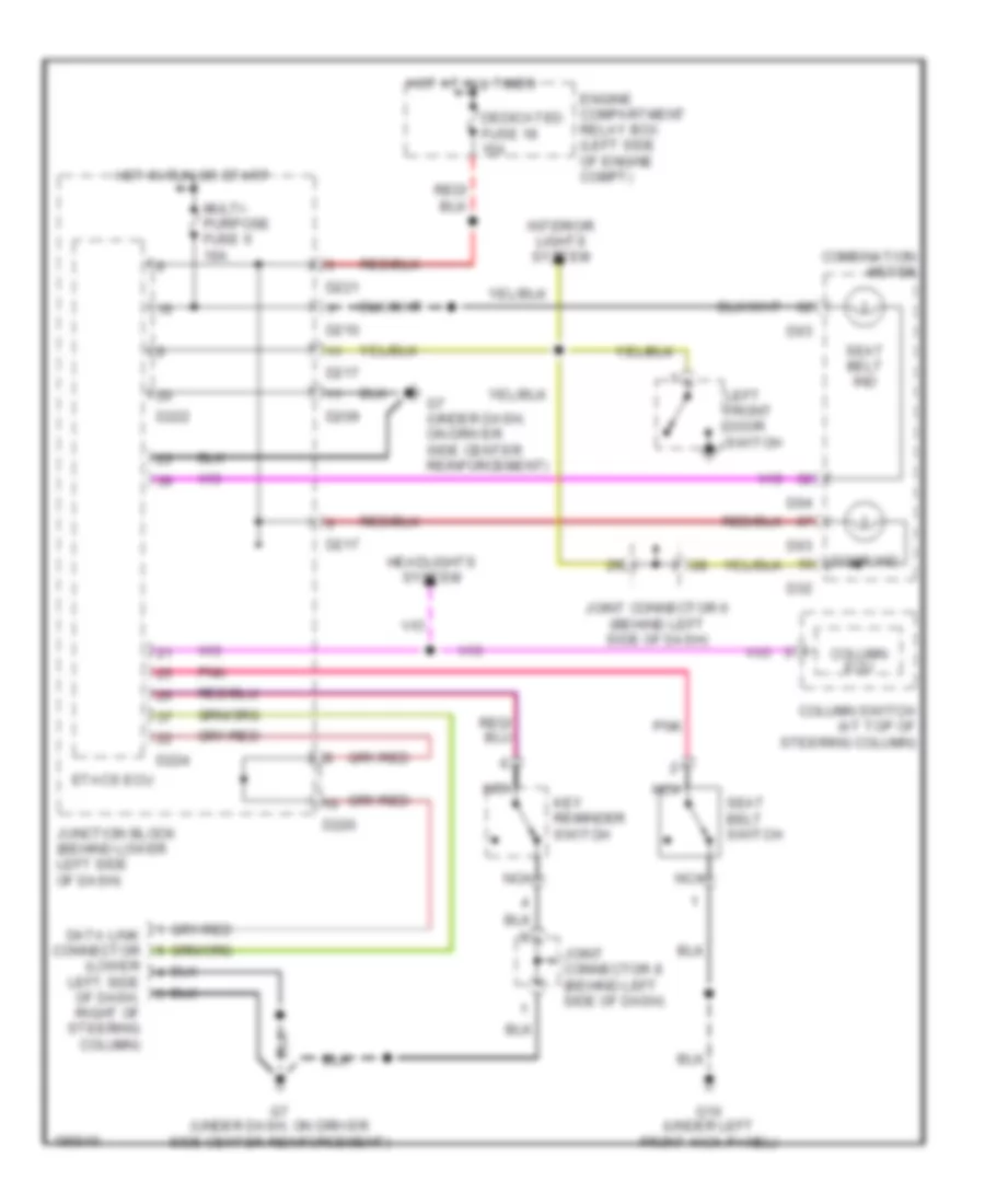
ANTI-THEFT
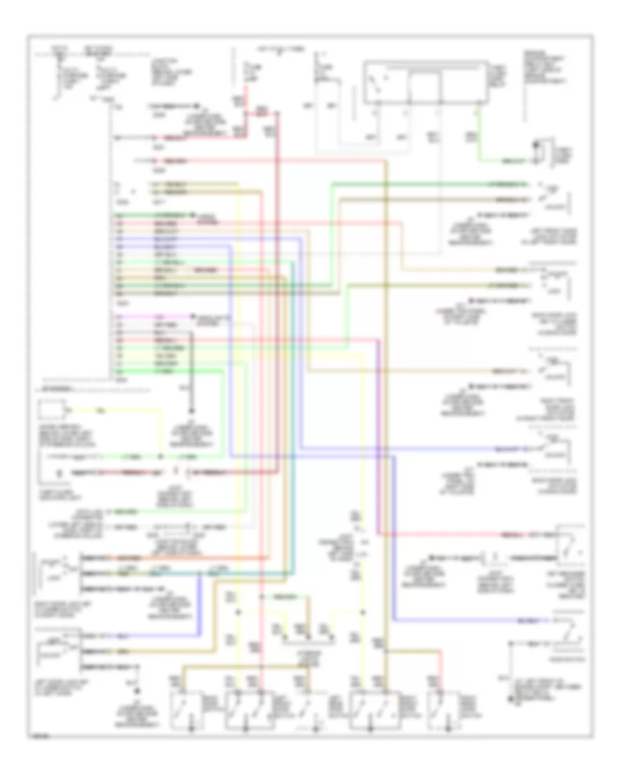
Forced Entry Wiring Diagram for Mitsubishi Montero Limited 2004
List of elements for Forced Entry Wiring Diagram for Mitsubishi Montero Limited 2004:
- (at left front of engine compt, between relay box & fender panel) g6
- (lower left side of dash, right of steering column)
- Back door lock actuator (in back door)
- Back door lock key cylinder switch (in back door)
- Back door switch
- D209
- D217
- D220
- D221
- D222
- D223
- D224
- Data link connector
- Engine compartment relay box (left side of engine compartment)
- Etacs-ecu
- Fuse 10a
- Fuse 15a
- G17 (under trim panel, on right side of tailgate)
- G7 (under dash, on driver side center reinforcement)
- Headlights system
- Hood switch
- Horns system
- Hot at all times
- Hot in acc
- Hot in run or start
- Immobilizer ecu (behind lower left side of dash, right of steering column)
- Interior lights system
- Joint connector 6 (behind left side of dash)
- Joint connector 7 (behind left side of dash)
- Joint connector 8 (behind left side of dash)
- Junction block (behind lower left side of dash)
- Key reminder switch (closed when key is removed)
- Left door lock key cylinder switch (in left door)
- Left front door lock actuator (in left front door)
- Left front door switch
- Left rear door switch
- Lock
- Multi- purpose fuse 1 15a
- Multi- purpose fuse 6 10a
- Nca
- Off
- Right door lock key cylinder switch (in right door)
- Right front door lock actuator (in right front door)
- Right front door switch
- Right rear door switch
- Theft alarm horn relay
- Theft- alarm horn
- Theft-alarm indicator light
- Unlock
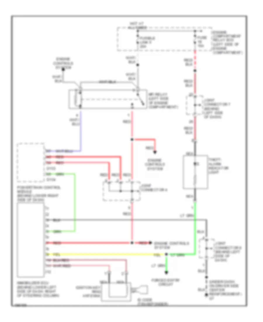
Immobilizer Wiring Diagram for Mitsubishi Montero Limited 2004
List of elements for Immobilizer Wiring Diagram for Mitsubishi Montero Limited 2004:
- (under dash, on driver side center reinforcement) g7
- All times
- D133
- D134
- Engine compartment relay box (left side of engine compartment)
- Engine controls system
- Forced entry circuit
- Fuse 15a
- Fusible link 5 20a
- Hot at
- Id code (transponder)
- Ignition key ring antenna
- Immobilizer ecu (behind lower left side of dash, right of steering column)
- Joint connector 4
- Joint connector 7 (behind left side of dash)
- Joint connector 8 (behind left side of dash)
- Mfi relay (left side of engine compartment)
- Nca
- Powertrain control module (behind lower right side of dash)
- Red
- Theft- alarm indicator light
BODY CONTROL MODULES
Body Control Modules Wiring Diagram for Mitsubishi Montero Limited 2004
List of elements for Body Control Modules Wiring Diagram for Mitsubishi Montero Limited 2004:
- (behind left
- A07x
- A08x
- All times
- Anti-theft system
- Anti-theft, headlights systems
- Computer data lines system
- D207
- D209
- D210
- D212
- D217
- D221
- D222
- D223
- D224
- Dedicated fuse 15 10a
- Dedicated fuse 18 15a
- Door locks system
- Door locks, anti-theft systems
- Door locks, interior lights systems
- Engine compartment relay box (left side of engine compartment)
- Etacs ecu
- Exterior lights system
- Front ecu
- G6 (at left front of engine compartment, between relay box & fender panel)
- G7 (under dash, on driver side center reinforcement)
- Headlights system
- Horns system
- Hot
- Hot at
- Hot in
- Hot in on
- In run
- Interior lights system
- Interior lights, door locks systems
- Junction block (behind lower left side of dash)
- Multi- purpose fuse 1 15a
- Multi- purpose fuse 10 20a
- Multi- purpose fuse 5 10a
- Multi- purpose fuse 6 10a
- On or acc
- Or start
- Pnk
- Power windows system
- Power windows, anti-theft systems
- Red
- Side of dash) joint connector 7
- Warning system
- Wiper/ washer system
- Wiper/washer system
- Wiper/washer, headlights systems
COMPUTER DATA LINES
Computer Data Lines Wiring Diagram for Mitsubishi Montero Limited 2004
List of elements for Computer Data Lines Wiring Diagram for Mitsubishi Montero Limited 2004:
- "g" & yaw rate sensor (in center console, rear of parking brake lever)
- A/c ecu (behind center of dash)
- A08x
- Column switch (at top of steering column)
- D08
- D117
- D118
- D134
- D210
- D224
- D23
- D24
- Data link connector (lower left side of dash, right of steering column)
- E109
- E119
- E121
- Etacs ecu
- Front ecu (in engine compt
- G7 (under dash, on driver side center reinforcement)
- Hot at all times
- Joint connector 4
- Joint connector 5 (behind left end of dash)
- Joint connector 7 (behind left side of dash)
- Joint connector 9
- Junction block (behind lower left side of dash)
- M-astc ecu (behind center
- Multi- purpose fuse 10 20a
- Nca
- Of dash)
- Powertrain control module (behind lower right side of dash)
- Red
- Relay box)
- Resistor
- Rv meter
- Srs ecu (under front of center console)
- Steering wheel sensor (on left side of upper steering column)
- Sunroof motor assembly (at front of
- Sunroof opening)
- Transfer ecu (behind center of dash)
- W/ rv meter
- W/o rv meter
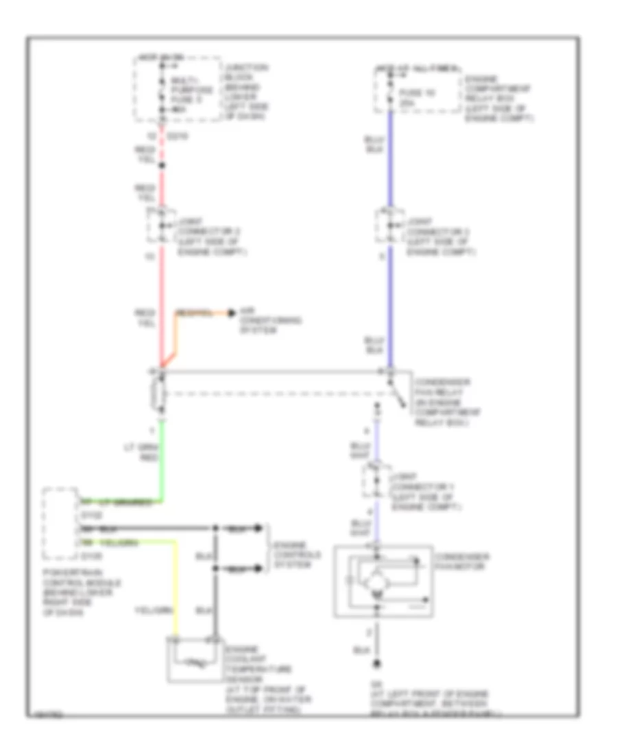
COOLING FAN
Cooling Fan Wiring Diagram for Mitsubishi Montero Limited 2004
List of elements for Cooling Fan Wiring Diagram for Mitsubishi Montero Limited 2004:
- Air conditioning system
- Condenser fan motor
- Condenser fan relay (in engine compartment relay box)
- D132
- D135
- D210
- Engine compartment relay box (left side of engine compt)
- Engine controls system
- Engine coolant temperature sensor (at top front of engine, on water outlet fitting)
- Fuse 10 25a
- G6 (at left front of engine compartment, between relay box & fender panel)
- Hot at all times
- Hot in on
- Joint connector 1 (left side of engine compt)
- Joint connector 2 (left side of engine compt)
- Joint connector 3 (left side of engine compt)
- Junction block (behind lower left side of dash)
- Multi- purpose fuse 5 10a
- Powertrain control module (behind lower right side of dash)
CRUISE CONTROL
Cruise Control Wiring Diagram for Mitsubishi Montero Limited 2004
List of elements for Cruise Control Wiring Diagram for Mitsubishi Montero Limited 2004:
- (left side of engine compartment)
- Accelerator pedal position
- Accelerator pedal position sensor (on top of accelerator pedal bracket)
- Auto-cruise control switch
- Can
- Clock- spring
- Combination meter
- Cruise ind
- D03
- D04
- D132
- D133
- D134
- D135
- D136
- D205
- D210
- D212
- D226
- D32
- Engine compartment relay box
- Engine controls system
- Exterior lights system
- G10 (under left front kick panel)
- G16 (under rear of center console)
- G9 (under right front kick panel, below powertrain control module)
- Hot at all times
- Hot in on
- Interior lights system
- Joint connector 4
- Joint connector 5 (behind left end of dash)
- Junction block (behind lower left side of dash)
- Main
- Multi- purpose fuse 16 15a
- Multi- purpose fuse 6 10a
- Off
- Or start
- Pnk
- Powertrain control module (behind lower right side of dash)
- Red
- Res
- Set
- Stoplight switch
- Sub
- Switch
- Throttle actuator control motor
- Throttle position sensor (on throttle body assembly)
- Transmissions system
- Vehicle speed sensor (on top of transfer case rear cover)
DEFOGGERS
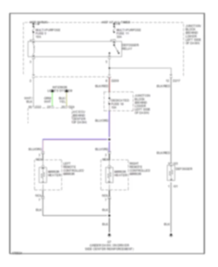
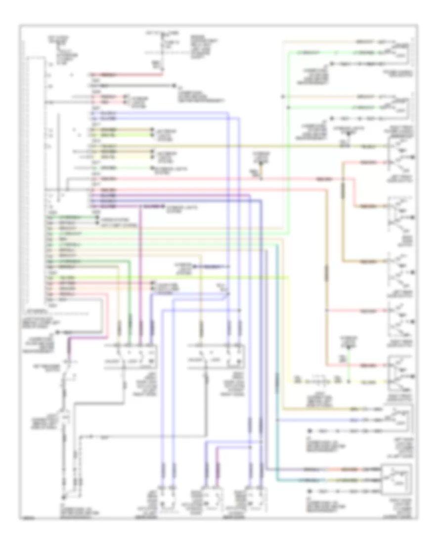
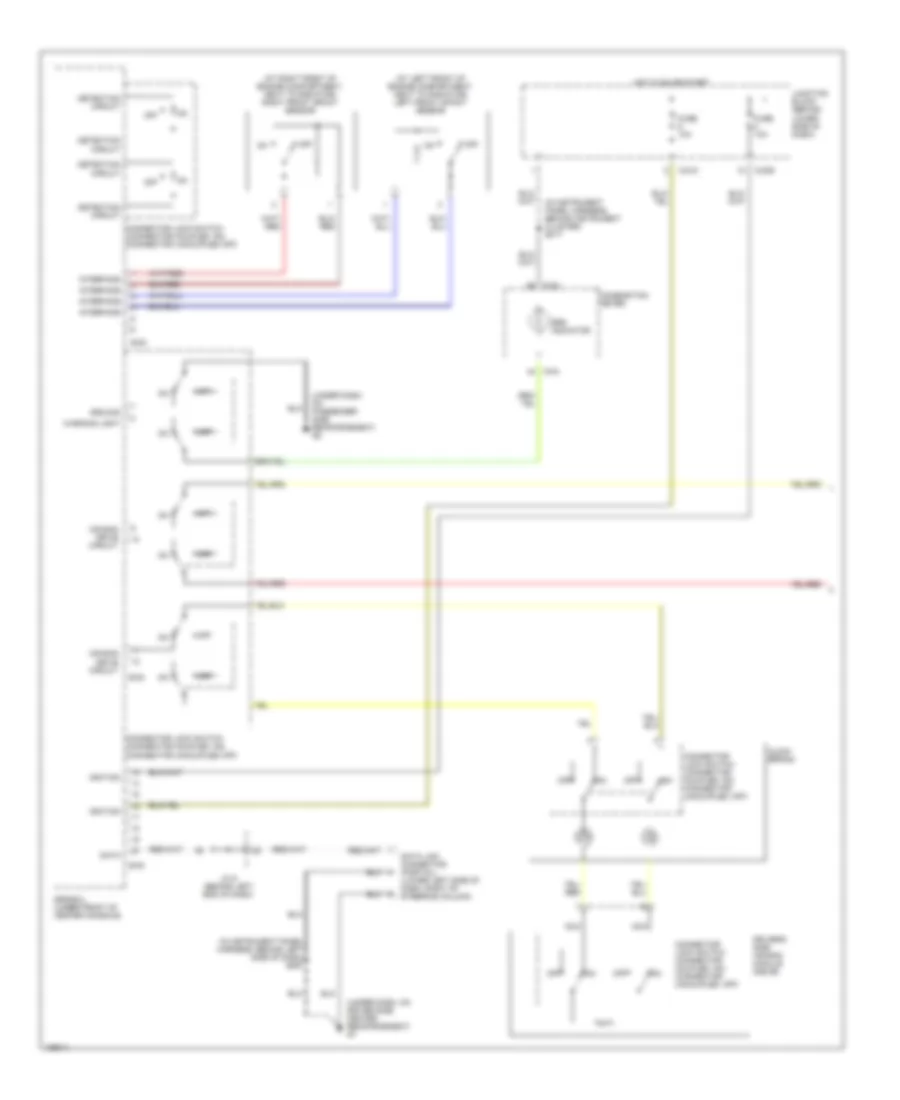
Defoggers Wiring Diagram, with Auto A/C for Mitsubishi Montero Limited 2004
List of elements for Defoggers Wiring Diagram, with Auto A/C for Mitsubishi Montero Limited 2004:
- A/c ecu (behind center of dash)
- D209
- D217
- D23
- D24
- Dedicated fuse 18 10a
- Defogger
- Defogger relay
- G7 (under dash, on driver side center reinforcement)
- Hot at all times
- Hot in run
- I01
- I03
- Interior lights system
- Junction block (behind lower left side of dash)
- Left remote controlled mirror
- Mirror heater
- Multi-purpose fuse 11 30a
- Multi-purpose fuse 5 10a
- Nca
- Right remote controlled mirror
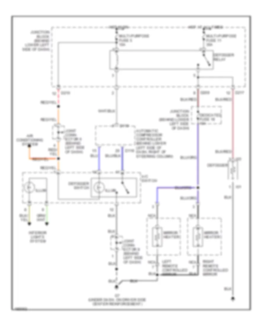
Defoggers Wiring Diagram, with Manual A/C for Mitsubishi Montero Limited 2004
List of elements for Defoggers Wiring Diagram, with Manual A/C for Mitsubishi Montero Limited 2004:
- A/c switch
- Air conditioning system
- Automatic compressor controller (behind lower left side of dash, right of steering column)
- D119
- D209
- D210
- D217
- Dedicated fuse 18 10a
- Defogger
- Defogger relay
- Defogger switch
- G7 (under dash, on driver side center reinforcement)
- Hot at all times
- Hot in on
- I01
- I03
- Illum
- Interior lights system
- Joint conn- ector 6 (behind left side of dash)
- Joint conn- ector 8 (behind left side of dash)
- Junction block (behind lower left side of dash)
- Left remote controlled mirror
- Mirror heater
- Multi-purpose fuse 11 30a
- Multi-purpose fuse 5 10a
- Nca
- Right remote controlled mirror
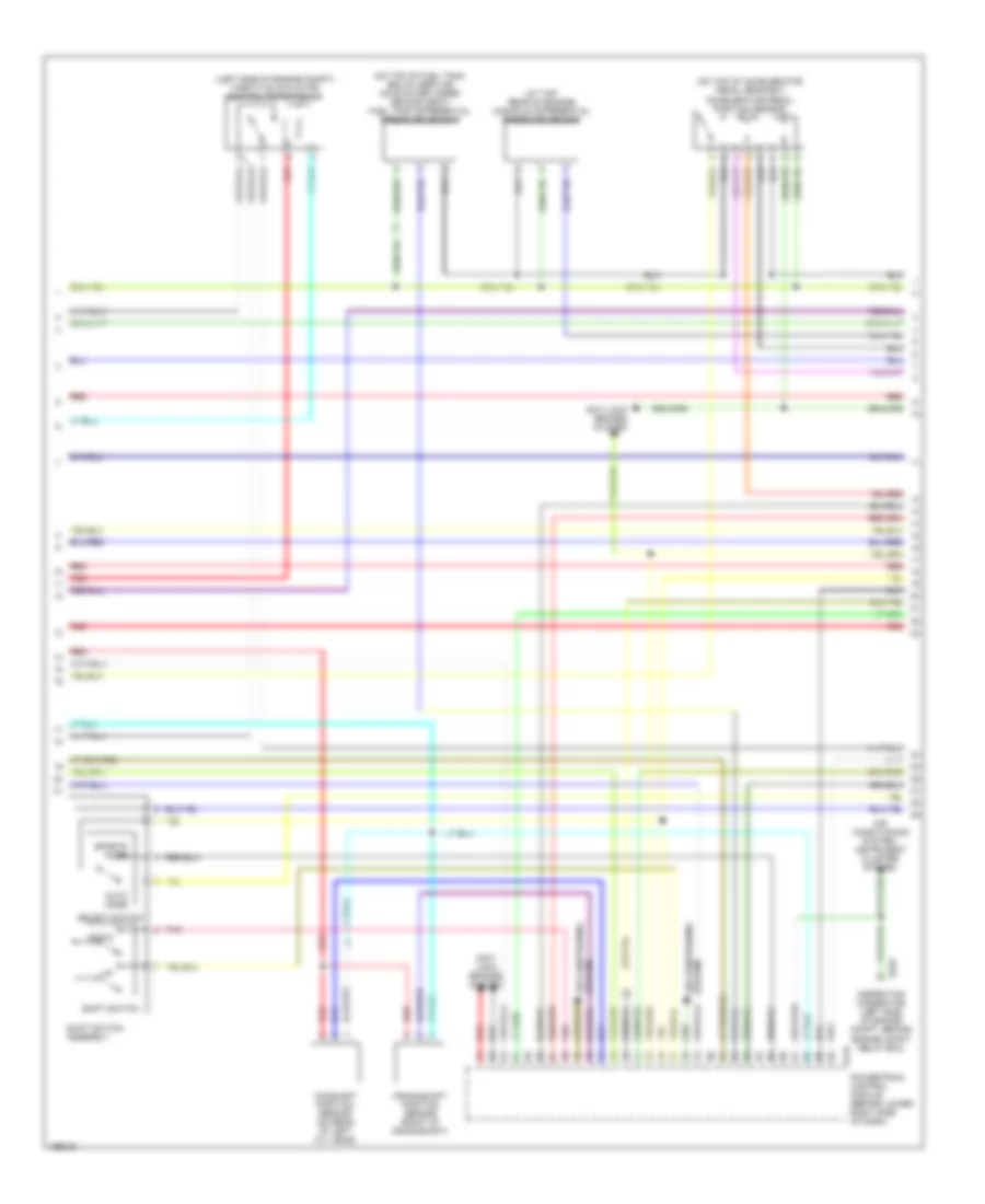
ENGINE PERFORMANCE
3.8L
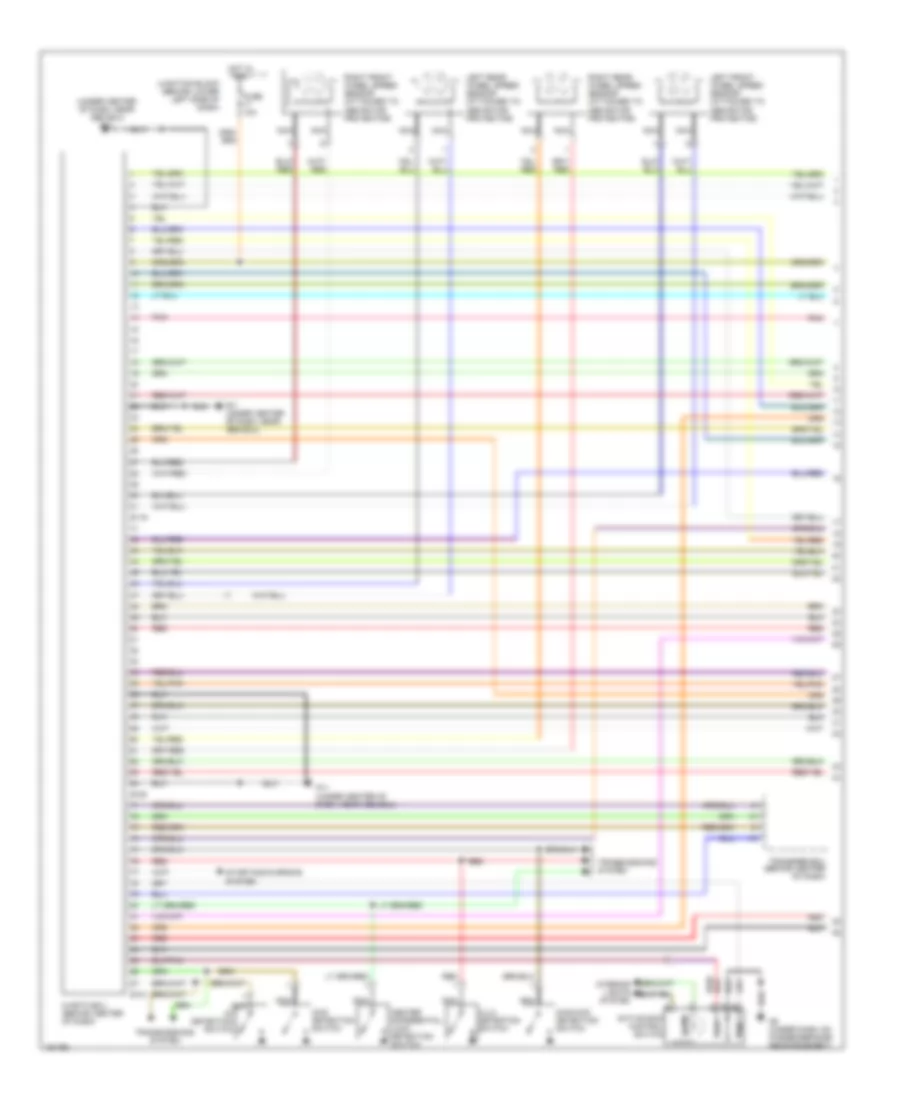
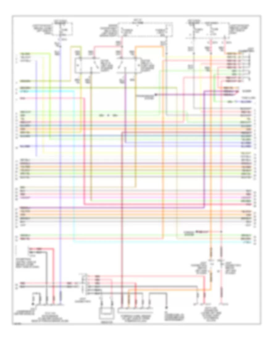
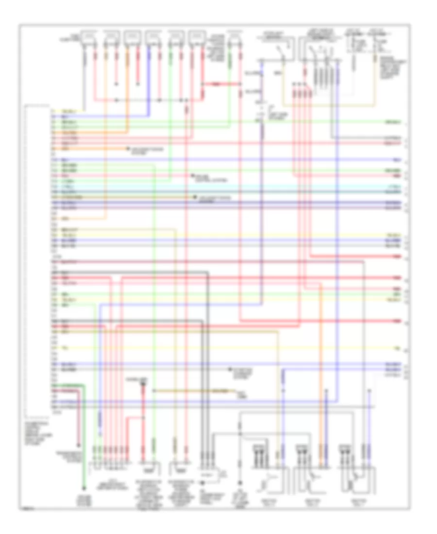
3.8L, Engine Performance Wiring Diagram (1 of 5) for Mitsubishi Montero Limited 2004
List of elements for 3.8L, Engine Performance Wiring Diagram (1 of 5) for Mitsubishi Montero Limited 2004:
- (left side of engine compt) mfi relay
- (not used)
- Air conditioning system
- Cruise control system
- D132
- D133
- Engine compartment relay box (left side of engine compt)
- Evaporative emission purge solenoid (center rear of engine compt)
- Evaporative emission ventilation solenoid (at right rear corner of vehicle, near fuel tank)
- Fuel injectors
- Fuse 15a
- Fuse link 5 20a
- G2 (on top of left cylinder head)
- G9 (under right front kick panel)
- Hot at all times
- Ignition coil 1
- Ignition coil 2
- Ignition coil 3
- Immobilizer ecu
- Intake manifold tuning solenoid (on top left side of eng)
- J/c (left side of dash)
- J/c 4 (behind right center of dash)
- J/c d14
- Nca
- Pnk
- Powertrain control module (behind lower right side of dash)
- Red
- Spark plugs
- Starting/ charging system
- Stoplight switch
- Transmission controls system
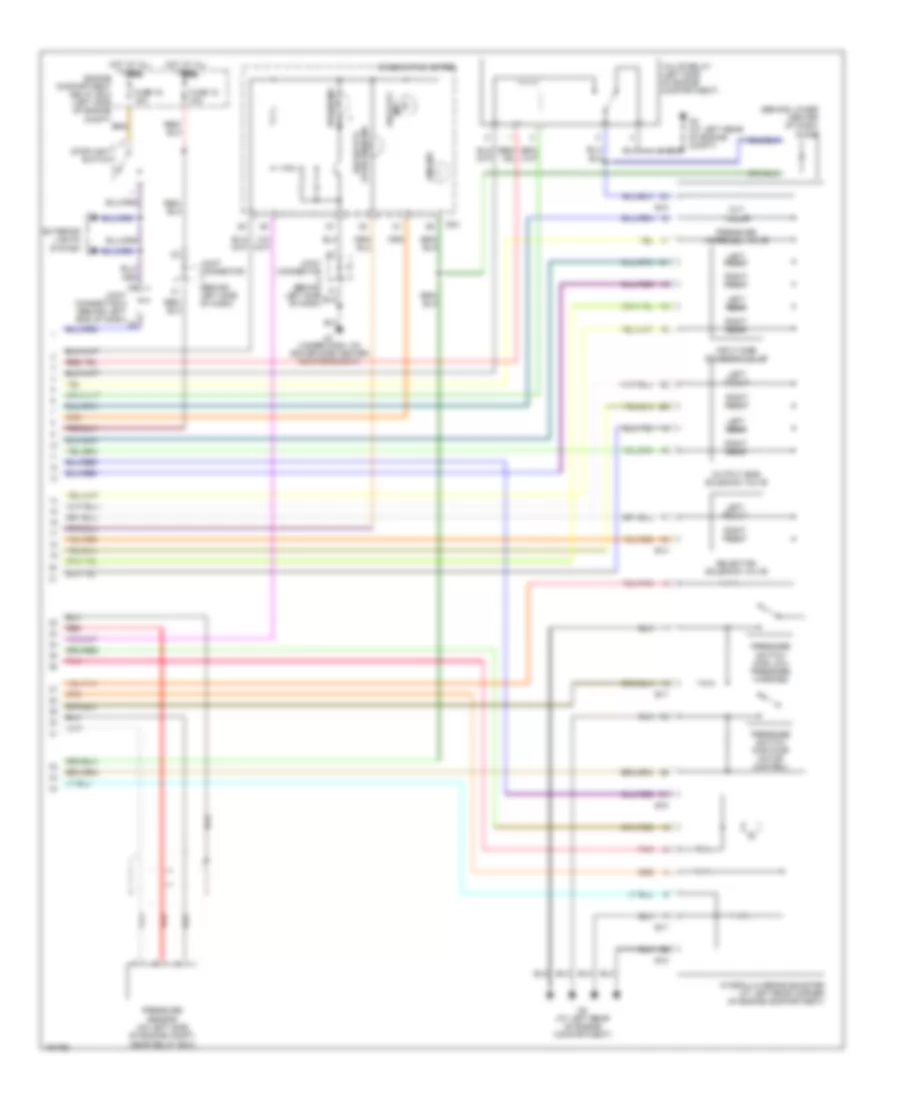
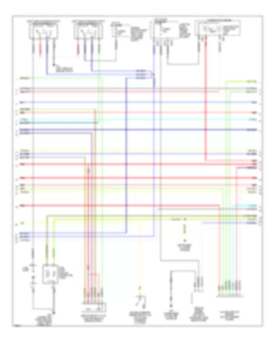
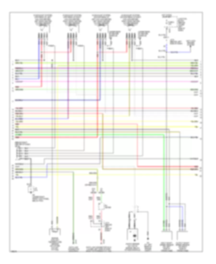
3.8L, Engine Performance Wiring Diagram (2 of 5) for Mitsubishi Montero Limited 2004
List of elements for 3.8L, Engine Performance Wiring Diagram (2 of 5) for Mitsubishi Montero Limited 2004:
- (left side of engine compt) fuel pump relay 1
- (left side of engine compt) fuel pump relay 2
- A/t temp
- Combination meter
- D03
- D04
- D210
- D212
- D221
- Egr solenoid valve (center rear of engine compt)
- Engine compartment relay box (left side of engine compt)
- Fuel pump
- Fuel pump module (inside fuel tank)
- Fuse 6 10a
- Fuse 6 20a
- G15 (under trim panel behind right rear wheelwell)
- G16 (under rear of center console)
- G3 (left rear of engine compt)
- Hot at all times
- Hot in run or start
- Instrument cluster system
- Junction block (behind lower left side of dash)
- Malfunction indicator lamp (mil)
- Power steering pressure switch (on power steering oil pump)
- Red
- Vehicle speed sensor (on top of transfer case rear cover)
- Volume airflow sensor (on air cleaner cover)
3.8L, Engine Performance Wiring Diagram (3 of 5) for Mitsubishi Montero Limited 2004
List of elements for 3.8L, Engine Performance Wiring Diagram (3 of 5) for Mitsubishi Montero Limited 2004:
- (at top rear of engine) manifold differential pressure sensor
- (left side of engine compt) throttle actuator control motor relay
- (on top of accelerator pedal bracket) accelerator pedal position sensor
- (on top of fuel tank, below service hole cover under second seat) fuel tank differential pressure sensor
- Air conditioning system
- Air conditioning system, instrument cluster system
- Anti- lock brakes system
- Anti-lock brakes system
- Auto mode
- B25x
- Camshaft position sensor (on rear of left cyl head)
- Crankshaft position sensor (right of crankshaft)
- D134
- Down
- Inspection connector (left side of engine compt, behind engine compt relay box)
- Pnk
- Powertrain control module (behind lower right side of dash)
- Red
- Select switch
- Shift switch
- Shift switch assembly
- Sports mode
3.8L, Engine Performance Wiring Diagram (4 of 5) for Mitsubishi Montero Limited 2004
List of elements for 3.8L, Engine Performance Wiring Diagram (4 of 5) for Mitsubishi Montero Limited 2004:
- (behind right center of dash) j/c 4
- (in exhaust system, downstream of left mini converter) left bank heated oxygen sensor (rear)
- (in exhaust system, downstream of right mini converter) right bank heated oxygen sensor (rear)
- (in exhaust system, upstream of left mini converter) left bank heated oxygen sensor (front)
- (in exhaust system, upstream of right mini converter) right bank heated oxygen sensor (front)
- (under rear of center console) g16
- Anti-lock brakes system
- D117
- D118
- D212
- Data link connector (dlc) (lower left side of dash, right of steering column)
- Data link connector (non-obdii)
- Engine coolant temperature sensor (on water outlet fitting)
- Fuse 8 10a
- G3 (at left rear of engine compt)
- G9 (under right front kick panel, below pcm)
- Hot in run or start
- Input shaft speed sensor (on left side of trans case)
- J/c 5 (behind left side of dash)
- J/c 6 (behind left side of dash)
- J/c d14
- Junction block (behind lower left side of dash)
- Knock sensor (on top of engine, below intake manifold)
- Nca
- Output shaft speed sensor (on right side of trans case)
- Red
- Rv meter
- W/ rv meter
- W/o rv meter
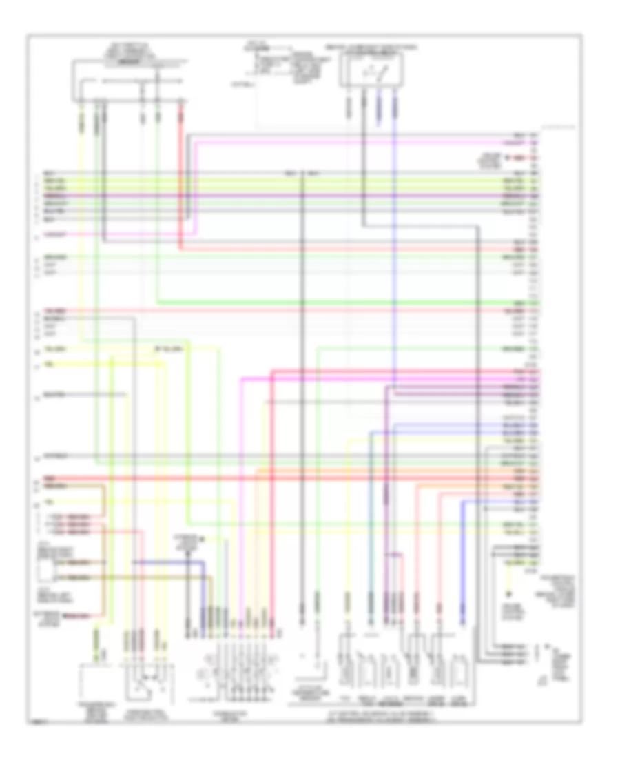
3.8L, Engine Performance Wiring Diagram (5 of 5) for Mitsubishi Montero Limited 2004
List of elements for 3.8L, Engine Performance Wiring Diagram (5 of 5) for Mitsubishi Montero Limited 2004:
- (behind lower right side of dash) a/t control relay
- (on throttle body assembly) throttle position sensor
- A/t control solenoid valve assembly (on transmission valve body assembly)
- A/t fluid temperature sensor
- Combination meter
- Cruise control system
- D03
- D135
- D136
- D32
- Dedicated fuse 14 20a
- E104
- Engine compartment relay box (left side of engine compt)
- Exterior lights system
- G9 (under right front kick panel)
- Hot at all times
- Interior lights system
- J/c 4 (behind right side of dash)
- J/c 5 (behind left side of dash)
- J/c d14
- Low & reverse
- Over- drive
- Park/neutral position switch
- Pnk
- Powertrain control module (behind lower right side of dash)
- Red
- Reduc- tion
- Second
- Tcc
- Transfer ecu (behind center of dash)
- Under- drive
EXTERIOR LIGHTS
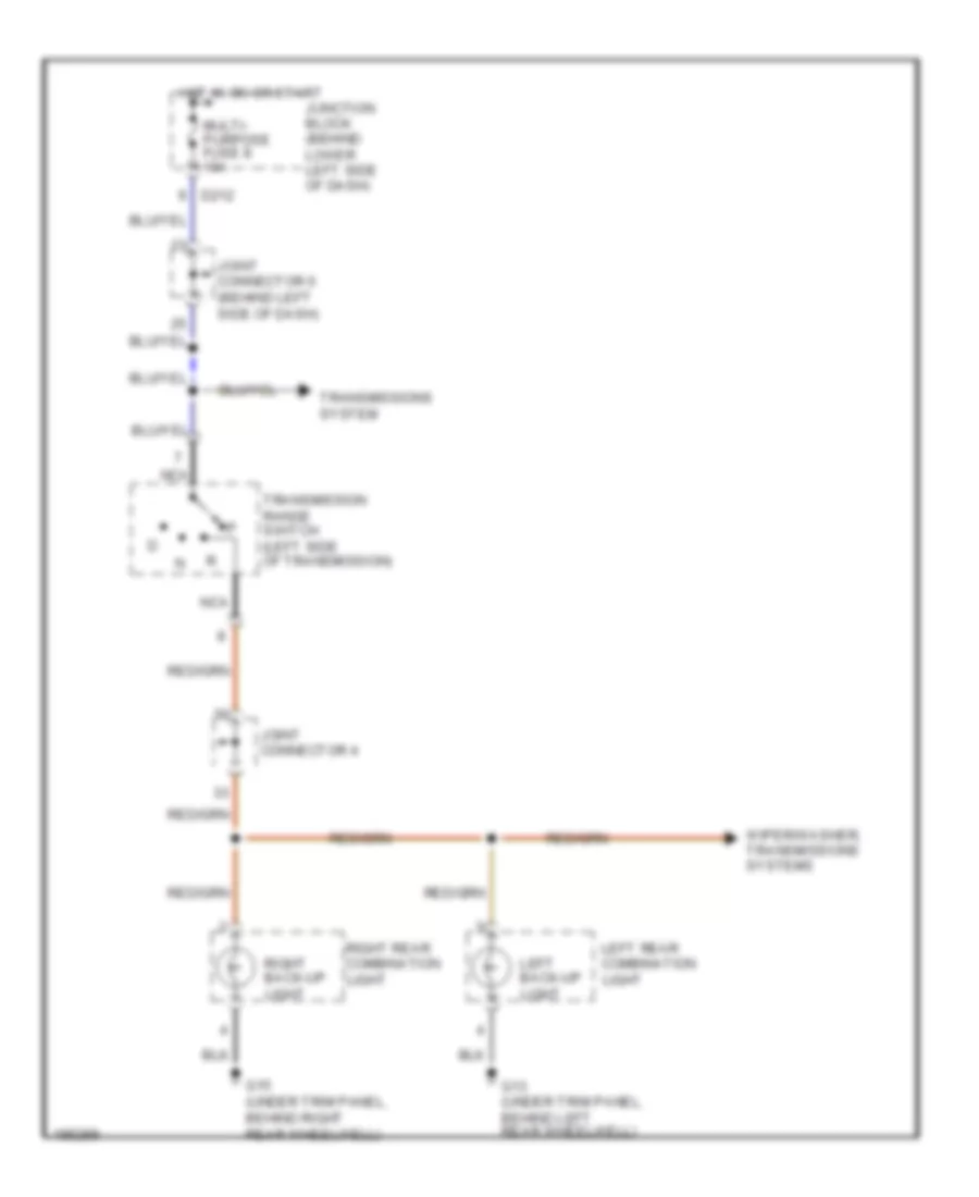
Back-up Lamps Wiring Diagram for Mitsubishi Montero Limited 2004
List of elements for Back-up Lamps Wiring Diagram for Mitsubishi Montero Limited 2004:
- D212
- G13 (under trim panel, behind left rear wheelwell)
- G15 (under trim panel, behind right rear wheelwell)
- Hot in on or start
- Joint connector 4
- Joint connector 6 (behind left side of dash)
- Junction block (behind lower left side of dash)
- Left back-up light
- Left rear combination light
- Multi- purpose fuse 8 10a
- Nca
- Right back-up light
- Right rear combination light
- Transmission range switch (left side of transmission)
- Transmissions system
- Wiper/washer, transmissions systems
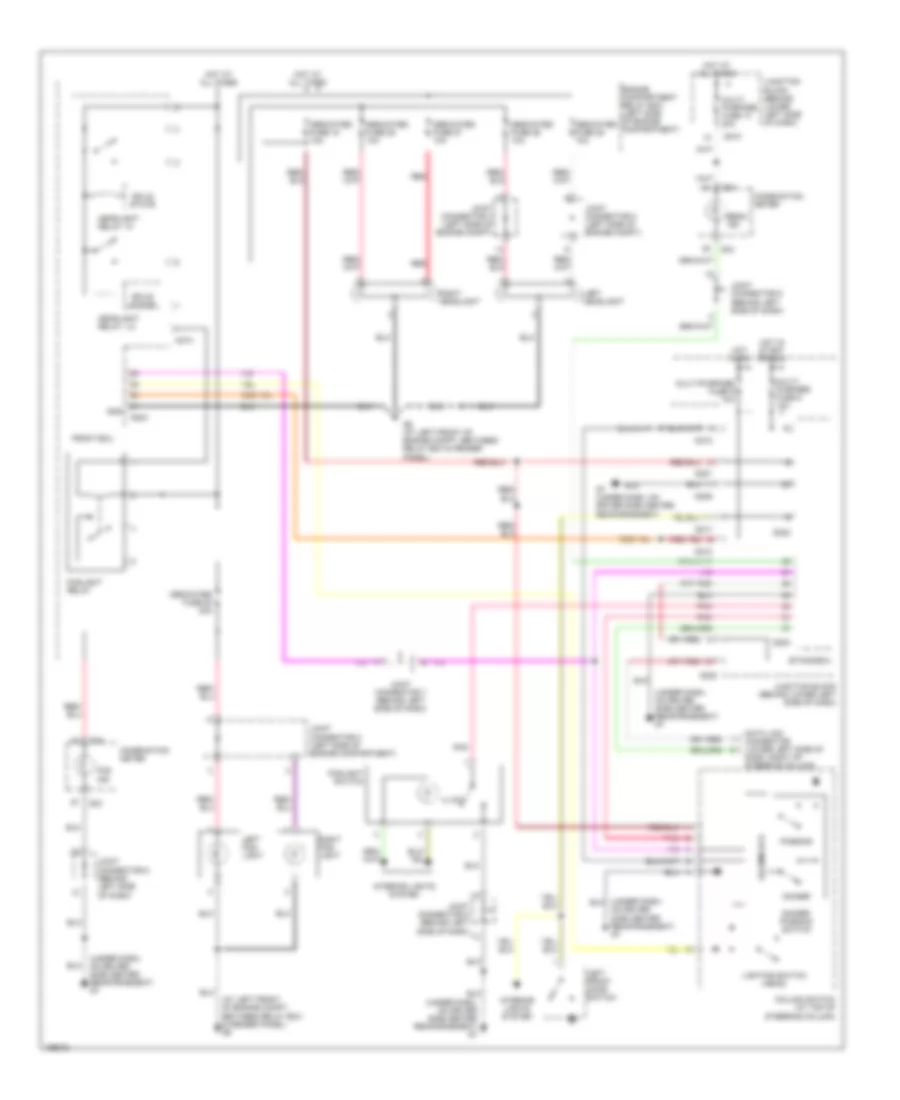
Exterior Lamps Wiring Diagram (1 of 2) for Mitsubishi Montero Limited 2004
List of elements for Exterior Lamps Wiring Diagram (1 of 2) for Mitsubishi Montero Limited 2004:
- (at left front of engine compt, between relay box & fender panel) g6
- (under dash, on driver side center reinforcement) g7
- A07x
- A08x
- Column ecu
- Column switch (at top of steering column)
- Combination meter
- D03
- D04
- D209
- D210
- D212
- D217
- D220
- D221
- D222
- D224
- D30
- Data link connector (lower left side of dash, right of steering column)
- Dedicated fuse 10a
- Dedicated fuse 15a
- Engine compartment relay box (left side of engine compt)
- Etacs ecu
- Front ecu
- G4 (at right front of engine compt, near air filter)
- G7 (under dash, on driver side center reinforcement)
- Hazard warning light switch
- Head
- Hot at all times
- Hot in on
- Hot in on or start
- Interior lights system
- Joint connector (behind left side of dash)
- Joint connector 1 (left side of engine compt)
- Joint connector 8 (behind left side of dash)
- Junction block (behind lower left side of dash)
- Left
- Left front turn signal light
- Left turn ind
- Lighting switch
- Multi- purpose fuse 6 10a
- Multi-purpose fuse 5 10a
- Off
- Pnk
- Right
- Right front turn signal light
- Right turn ind
- Starting/ charging system
- Tail
- Turn signal switches
Exterior Lamps Wiring Diagram (2 of 2) for Mitsubishi Montero Limited 2004
List of elements for Exterior Lamps Wiring Diagram (2 of 2) for Mitsubishi Montero Limited 2004:
- (under trim panel, behind right rear wheelwell) g15
- (under trim panel, on right side of tailgate) g17
- Dedicated fuse 15a
- Engine compartment relay box (left side of engine compt)
- G13 (under trim panel, behind left rear wheelwell)
- G15 (under trim panel, behind right rear wheelwell)
- G17 (under trim panel, on right side of tailgate)
- G6 (at left front of engine compartment, between relay box & fender panel)
- High- mounted stop light
- Hot at all times
- Interior lights system
- Left lamp
- Left position light
- Left rear combination light
- Left rear light
- License plate light assembly
- Nca
- Right lamp
- Right position light
- Right rear combination light
- Right rear light
- Side marker light
- Stop light
- Stoplight switch
- Tail- light
- Transmissions, anti-lock brakes, cruise control, anti-theft systems
- Turn signal light
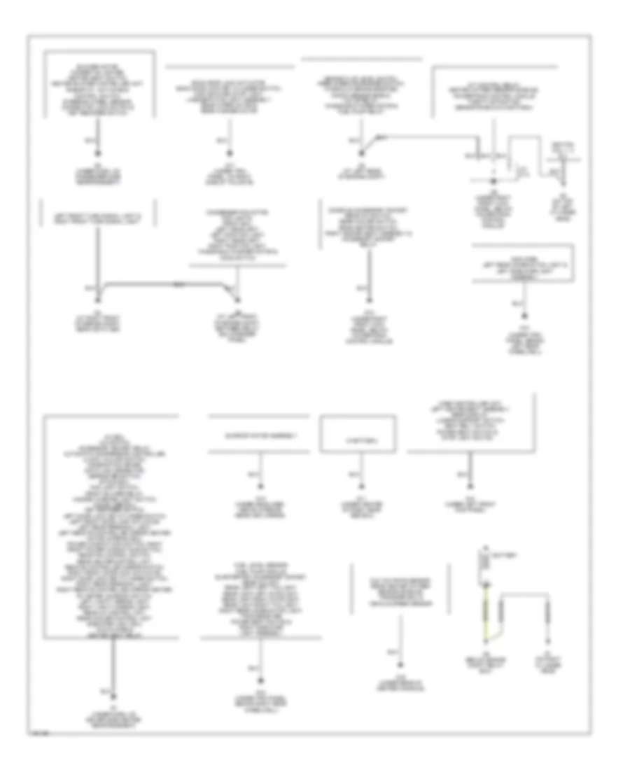
GROUND DISTRIBUTION
Ground Distribution Wiring Diagram for Mitsubishi Montero Limited 2004
List of elements for Ground Distribution Wiring Diagram for Mitsubishi Montero Limited 2004:
- (under trim panel, behind left rear wheelwell)
- A/c ecu, a/c switch, accessory socket relay, automatic compressor controller, clock, column switch, combination meter, data link connector, defroster switch, etacs ecu, fog light switch, front blower relay, hazard warning light switch, immobilizer ecu, key reminder switch, left door lock key cylinder switch, left front door lock actuator, left rear personal light, left remote controlled mirror heater, motor antenna ecu, power window main switch, right front power window sub switch, rear fan control switch,
- A/t control relay, heated oxygen sensor shields, powertrain control module throttle position sensor shield & m-astc-ecu
- Amplifier, left rear combination light & left side step light assembly
- Back door lock actuator, back door lock key cylinder switch, high mounted stop light, license plate light assembly, rear wiper motor & rear washer motor
- Battery
- Blower motor, cigarette lighter, heated seat switch, heater blower controller unit,
- Brake fluid level switch, free wheeling engage switch, hydraulic brake booster, knock sensor shield, valve relay, windshield wiper motor & fuel pump relay
- Condenser fan motor, fog lights, front ecu, left headlight, left position light, right headlight, right position light, windshield washer motor & hood switch
- Console accessory socket, rear a/c switch, rear cooler switch, rear heater switch, right heated seat assembly & accessory socket relay
- Fuel level sensor, fuel pump module, quartertrim accessory socket, rear a/c unit, rear light-left taillight, rear light-left stoplight, rear light-right stoplight, rear light-right taillight, right rear combination light, tpms receiver, power seat switch & right side step light assembly
- G & yaw rate sensor, rear heated oxygen sensor shields, transfer ecu & vehicle speed sensor
- G1 (on right cylinder head)
- G10 (under left front kick panel)
- G11 (under center of dash, near abs ecu)
- G12 (under right front kick panel, below powertrain control module)
- G13
- G14 (under headliner, above interior rear view mirror)
- G15 (under trim panel, behind right rear wheelwell)
- G16 (under rear of center console)
- G17 (under trim panel, on right side of tailgate)
- G2 (on top of left cylinder head)
- G3 (at left rear of engine compt)
- G4 (at right front of engine compt, near air filter)
- G5 (below engine compt relay box)
- G6 (at left front of engine compt, between relay box & fender panel)
- G7 (under dash, on driver side center reinforcement)
- G8 (under dash, on passenger side reinforcement)
- G9 (under right front kick panel, below powertrain control module)
- Ignition coil 1, 2 & 3
- J/c d-14
- Left front turn signal light & right front turn signal light
- M-astc-ecu
- Power seat switch & stop light switch
- Rear heater control unit, remote controlled mirror switch, right front door lock actuator, right door lock key cylinder switch, right rear personal light, right remote controlled mirror heater, rv meter, sunroof switch, left vanity mirror light, right vanity mirror light, rear a/c control unit, rear cooler control unit, side step light ecu, dvd player & heated seat relay
- Rheostat, active skid control switch, steering wheel sensor, connector lock switch & key reminder switch
- Sunroof motor assembly
- Video controller unit, left heated seat assembly, rear display, lumbar support switch, seat belt switch,
HEADLIGHTS
Headlights Wiring Diagram for Mitsubishi Montero Limited 2004
List of elements for Headlights Wiring Diagram for Mitsubishi Montero Limited 2004:
- (at left front of engine compt, between relay box & fender panel) g6
- (under dash, on driver side center reinforcement) g7
- A07x
- A08x
- Beam ind
- Column ecu
- Column switch (at top of steering column)
- Combination meter
- D03
- D04
- D209
- D210
- D217
- D220
- D221
- D222
- D224
- Data link connector (lower left side of dash, right of steering column)
- Dedicated fuse 18 10a
- Dedicated fuse 20 20a
- Dedicated fuse 25 10a
- Dedicated fuse 26 10a
- Dedicated fuse 27 10a
- Dedicated fuse 28 10a
- Dimmer
- Dimmer- passing switch
- Engine compartment relay box (left side of engine compartment)
- Etacs-ecu
- Fog ind
- Foglight relay
- Foglight switch
- Front ecu
- G6 (at left front of engine compt, between relay box & fender panel)
- G7 (under dash, on driver side center reinforcement)
- Gnd
- Headlight relay: hi
- Headlight relay: lo
- Hot at all times
- Hot in on
- Hot in start or run
- Illum
- Interior lights system
- Joint connector 2 (left side of engine compartment)
- Joint connector 2 (left side of engine compt)
- Joint connector 3 (left side of engine compt)
- Joint connector 5 (behind left side of dash)
- Joint connector 7 (behind left side of dash)
- Joint connector 8 (behind left side of dash)
- Junction block (behind lower left side of dash)
- Left fog- light
- Left front door switch
- Left headlight
- Lighting switch (head)
- Multi- purpose fuse 10 20a
- Multi- purpose fuse 6 10a
- Multi-purpose fuse 5 10a
- On driver side center reinforcement) g7
- Passing
- Pnk
- Red
- Right fog- light
- Right headlight
- Solid state
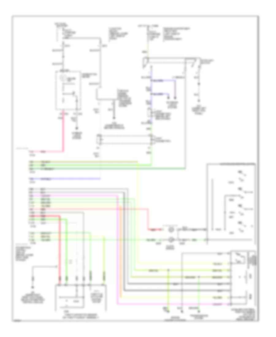
HORN
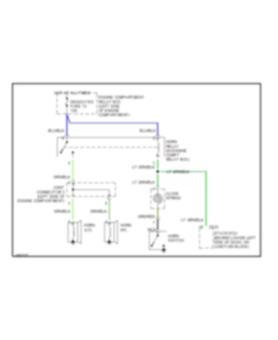
Horn Wiring Diagram for Mitsubishi Montero Limited 2004
List of elements for Horn Wiring Diagram for Mitsubishi Montero Limited 2004:
- Clock spring
- D223
- Dedicated fuse 13 10a
- Engine compartment relay box (left side of engine compartment)
- Etacs ecu (behind lower left side of dash, on junction block)
- Horn (hi)
- Horn (lo)
- Horn relay (in engine compt relay box)
- Horn switch
- Hot at all times
- Joint connector 3 (left side of engine compartment)
- Nca
INSTRUMENT CLUSTER
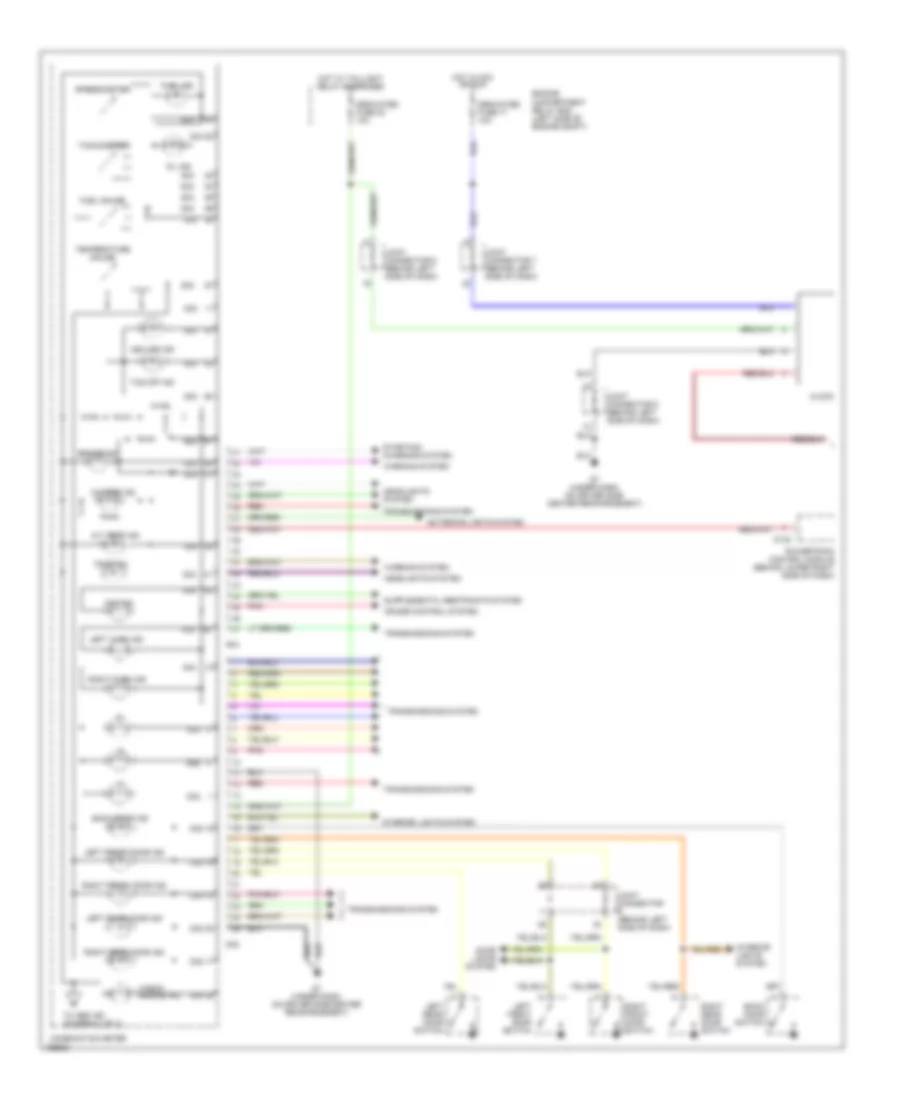
Instrument Cluster Wiring Diagram (1 of 2) for Mitsubishi Montero Limited 2004
List of elements for Instrument Cluster Wiring Diagram (1 of 2) for Mitsubishi Montero Limited 2004:
- A/t temp ind
- Asc off ind
- Back door ind
- Back door switch
- Brake ind
- Charge ind
- Check engine ind
- Clock
- Combination meter
- Cpu
- Cruise control system
- D03
- D03 52
- D04
- D04 38
- D132
- D32
- D32 16
- D32 17
- D32 18
- D32 19
- D32 20
- Dedicated fuse 17 10a
- Dedicated fuse 23 10a
- Door locks system
- Engine compartment relay box (left side of engine compt)
- Exterior lights system
- Fog ind
- Fuel gauge
- Fuel ind
- G7 (under dash, on driver side center reinforcement)
- Headlights system
- Hot in acc or run
- Hot w/ taillight relay energized
- Interior lights system
- Joint connector (behind left side of dash)
- Joint connector 6 (behind left side of dash)
- Joint connector 7 (behind left side of dash)
- Joint connector 8 (behind left side of dash)
- Left front door ind
- Left front door switch
- Left rear door ind
- Left rear door switch
- Left turn ind
- Oil ind
- Pnk
- Powertrain control module (behind lower right side of dash)
- Red
- Right front door ind
- Right front door switch
- Right rear door ind
- Right rear door switch
- Right turn ind
- Speedometer
- Starting/ charging system
- Tachometer
- Tcs off ind
- Temperature gauge
- To abs ind (diagram 2 of 2)
- Tpms ind
- Transmissions system
- Warning system
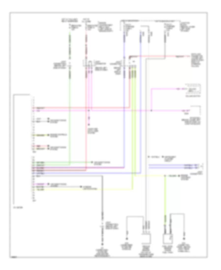
Instrument Cluster Wiring Diagram (2 of 2) for Mitsubishi Montero Limited 2004
List of elements for Instrument Cluster Wiring Diagram (2 of 2) for Mitsubishi Montero Limited 2004:
- (on top of transfer case rear cover)
- 4llc ind
- Abs ind
- Anti-lock brakes system
- Beam ind
- Brake fluid level switch (on master cylinder)
- C/d lock ind
- Combination meter
- Cruise ind
- D03
- D04
- D134
- D210
- D212
- D217
- D221
- D32
- Dedicated fuse 18 15a
- Engine compartment relay box (left side of engine compt)
- Engine controls system
- Engine coolant temperature sensor (at top front of engine, on water outlet fitting)
- Engine oil pressure switch (right front of engine)
- Exterior lights system
- From check eng ind a (diagram 1 of 2)
- Fuel level sensor (inside fuel tank)
- G15 (under trim panel, behind right rear wheelwell)
- G16 (under rear of center console)
- G3 (at left rear of engine compt)
- G7 (under dash, on driver side center reinforcement)
- Hot at all times
- Hot in run or start
- Illumination
- Joint connector
- Joint connector 4
- Joint connector 5 (behind left end of dash)
- Joint connector 7 (behind left side of dash)
- Junction block (behind lower left side of dash)
- Lf wheel ind
- Lr wheel ind
- Multi- purpose fuse 6 10a
- Nca
- Parking brake switch
- Powertrain control module (behind lower right side of dash)
- Rf wheel ind
- Rr wheel ind
- Rv meter circuit
- Seat belt ind
- Srs ind
- Transmissions system
- Vehicle speed sensor
RV Meter Wiring Diagram for Mitsubishi Montero Limited 2004
List of elements for RV Meter Wiring Diagram for Mitsubishi Montero Limited 2004:
- (on top of transfer case rear cover)
- Air conditioning system
- Column ecu
- Column switch
- Computer data lines system
- D07
- D08
- D210
- D212
- D220
- D224
- Data link connector (lower left side of dash, right of steering column)
- Dedicated fuse 18 10a
- Dedicated fuse 23 10a
- Engine compartment relay box (left side of engine compt)
- Engine controls system
- Etacs ecu (behind lower left side of dash, on junction block)
- Fuel level sensor (inside fuel tank)
- G15 (under trim panel, behind right rear wheelwell)
- G16 (under rear of center console)
- G7 (under dash, on driver side center reinforcement)
- Hot at all times
- Hot in acc or run
- Hot in run or start
- Hot w/ taillight relay energized
- Instrument cluster circuit
- Interior lights system
- Joint connector (behind left end of dash)
- Joint connector (behind left side of dash)
- Joint connector 4
- Joint connector 6 (behind left side of dash)
- Joint connector 8 (behind left side of dash)
- Junction block (behind lower left side of dash)
- Multi- purpose fuse 4 15a
- Multi- purpose fuse 6 10a
- Nca
- Red
- Rv meter
- Vehicle speed sensor
INTERIOR LIGHTS
Courtesy Lamps Wiring Diagram for Mitsubishi Montero Limited 2004
List of elements for Courtesy Lamps Wiring Diagram for Mitsubishi Montero Limited 2004:
- (under dash, on driver side center reinforcement) g7
- (w/ key removed)
- Back door ind
- Back door switch
- Cargo space light
- Combination meter
- D03
- D207
- D209
- D210
- D217
- D221
- D222
- D224
- D32
- Dedicated fuse 18 15a
- Dedicated fuse 23 10a
- Dome light
- Door
- Door locks system
- Engine compartment relay box (left side of engine compt)
- Etacs ecu
- Front
- Fuse 10a
- G10 (under left front kick panel)
- G15 (under trim panel, behind right rear wheelwell)
- G7 (under dash, on driver side center reinforcement)
- Glove box light
- Glove box light switch
- Hot at all times
- Hot in on or start
- Hot w/ taillight relay energized
- Ign pwr
- Ignition key hole illumination light
- Joint connector (behind left side of dash)
- Joint connector 6 (behind left side of dash)
- Joint connector 7 (behind left side of dash)
- Joint connector 8 (behind left side of dash)
- Junction block (behind lower left side of dash)
- Key reminder switch
- Left front door light
- Left front door switch
- Left rear door light
- Left rear door switch
- Left rear personal light
- Left side step light assembly
- Left vanity mirror light
- Lt ft door ind
- Lt rr door ind
- Map light
- Nca
- Off
- Off on
- Power distribution system
- Power tops system
- Rear
- Red
- Right front door light
- Right front door switch
- Right rear door light
- Right rear door switch
- Right rear personal light
- Right side step light assembly
- Right vanity mirror light
- Rt ft door ind
- Rt rr door ind
- Side step light ecu (behind left side of dash)
- Sound systems
- Warning system
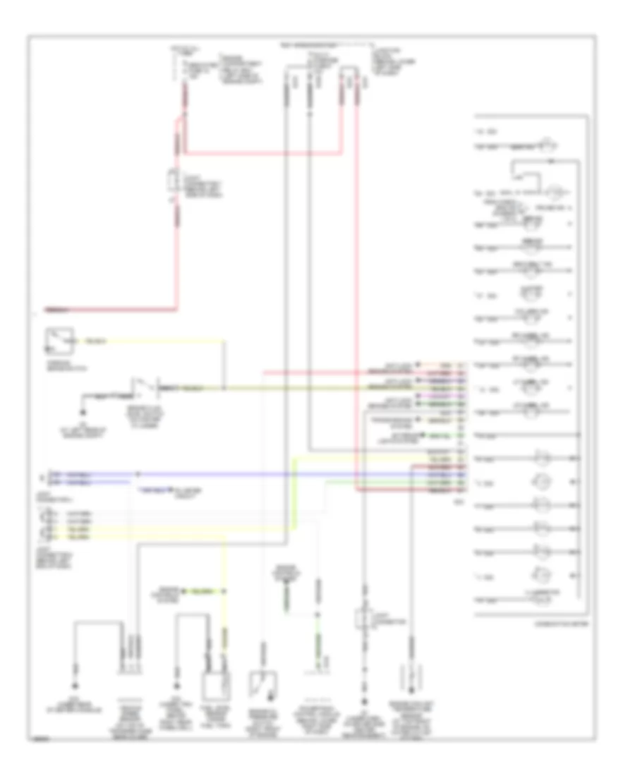
Instrument Illumination Wiring Diagram for Mitsubishi Montero Limited 2004
List of elements for Instrument Illumination Wiring Diagram for Mitsubishi Montero Limited 2004:
- (2 bulbs)
- (3 bulbs)
- (behind left side of dash) joint connector 8
- (manual a/c)
- A/c ecu (automatic a/c) (behind center of dash)
- A/c switch (manual a/c)
- A/t shift illumination light
- A/t shift illumination light (w/ active trac)
- A07x
- A08x
- Active skid control switch
- Air conditioning system
- Ashtray illumination light
- Automatic a/c
- Automatic compressor controller (behind lower left side of dash, right of steering column)
- Cigarette lighter illumination light
- Clock
- Column switch
- Column-ecu
- Combination meter
- Cruise control & a/t indicators
- D07
- D119
- D24
- D32
- Engine compartment relay box (at left side of engine compartment)
- Fog light switch
- Front ecu
- Front rear fan control switch
- Fuse 23 10a
- G7 (under dash, on driver side center reinforcement)
- G8 (under dash, on passenger side reinforcement)
- Hazard warning light switch
- Head
- Heated seat switch
- Heater control panel illumination light
- Hot at all times
- Illum
- Illumination
- Joint connector 6 (behind left side of dash)
- Joint connector 8 (behind left side of dash)
- Lighting switch
- Manual a/c
- Radio & cd player
- Rear cooler switch or rear a/c switch
- Rear heater switch or rear cooler switch
- Rheostat
- Rv meter
- Solid state
- Sunroof switch
- Tail
- Taillight relay
POWER ANTENNA
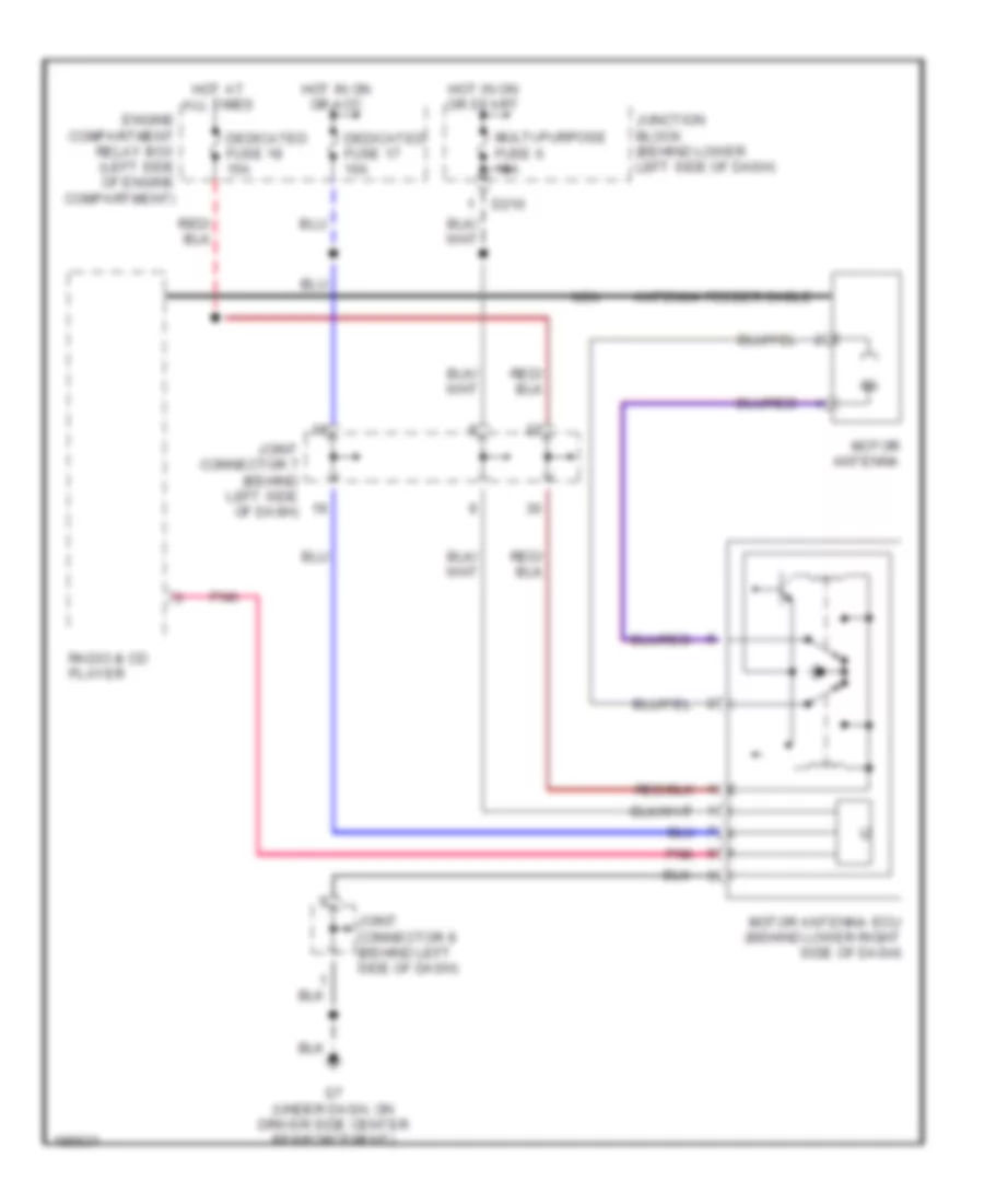
Power Antenna Wiring Diagram for Mitsubishi Montero Limited 2004
List of elements for Power Antenna Wiring Diagram for Mitsubishi Montero Limited 2004:
- Antenna feeder cable
- D210
- Dedicated fuse 17 10a
- Dedicated fuse 18 15a
- Engine compartment relay box (left side of engine compartment)
- G7 (under dash, on driver side center reinforcement)
- Hot at all times
- Hot in on or acc
- Hot in on or start
- Joint connector 7 (behind left side of dash)
- Joint connector 8 (behind left side of dash)
- Junction block (behind lower left side of dash)
- Motor antenna
- Motor antenna ecu (behind lower right side of dash)
- Multi-purpose fuse 6 10a
- Nca
- Pnk
- Radio & cd player
POWER DISTRIBUTION
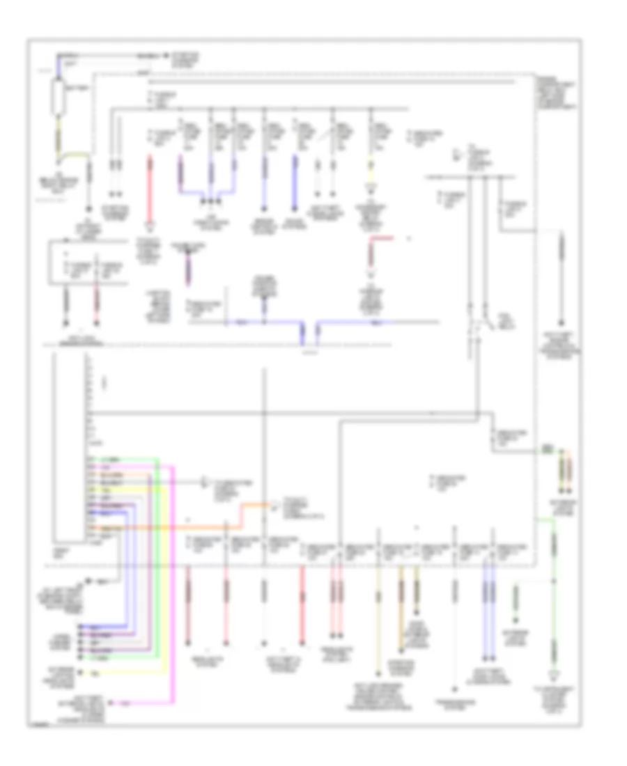
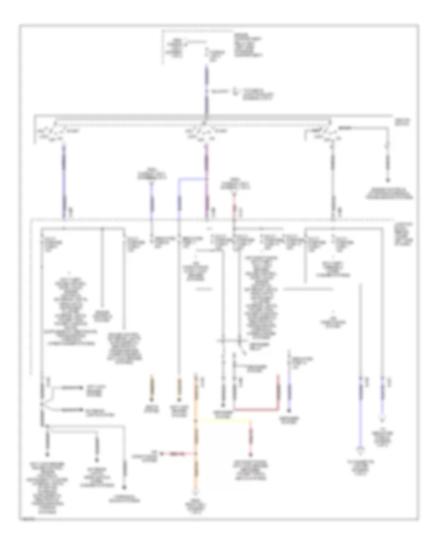
Power Distribution Wiring Diagram (1 of 3) for Mitsubishi Montero Limited 2004
List of elements for Power Distribution Wiring Diagram (1 of 3) for Mitsubishi Montero Limited 2004:
- A-07x
- A-08x
- Air conditioning system
- Anti-lock brakes system
- Anti-lock brakes, cruise control, engine controls, exterior lights & transmissions systems
- Anti-theft & door locks systems
- Anti-theft & headlights systems
- Anti-theft, door locks & horns system
- Anti-theft, engine controls & transmissions systems
- Anti-theft, exterior lights, headlights & wiper/ washer systems
- Battery
- Dedi- cated fuse 10a
- Dedi- cated fuse 15a
- Dedi- cated fuse 20a
- Dedi- cated fuse 25a
- Dedicated fuse 13 10a
- Dedicated fuse 14 20a
- Dedicated fuse 15 10a
- Dedicated fuse 16 15a
- Dedicated fuse 18 15a
- Dedicated fuse 19 20a
- Dedicated fuse 20 20a
- Dedicated fuse 23 10a
- Dedicated fuse 24 10a
- Dedicated fuse 25 10a
- Dedicated fuse 26 10a
- Dedicated fuse 27 10a
- Dedicated fuse 28 10a
- Door locks & exterior lights systems
- Engine compartment relay box (left side of engine compartment)
- Engine controls system
- Exterior lights & headlights systems
- Exterior lights system
- Fog- light relay
- Front ecu
- Fusible link 1 120a
- Fusible link 2 60a
- Fusible link 31 60a
- Fusible link 32 40a
- Fusible link 4 30a
- Fusible link 5 20a
- G1 (on right cylinder head)
- G5 (below engine compt relay box)
- G6 (at left front of engine compt, between relay box & fender panel)
- Headlights system
- Headlights system (fog light)
- Junction block (behind lower left side of dash)
- Power tops system
- Power windows & seats systems
- Red
- Sound systems
- Starting/ charging system
- To accessory socket relay (diagram 3 of 3)
- To dedicated fuse 22 (diagram 3 of 3)
- To fusible link 3 (diagram 2 of 3)
- To instrument cluster system (diagram 3 of 3)
- To interior lights system (diagram 3 of 3)
- To multi- purpose fuse 11 (diagram 2 of 3)
- To multi- purpose fuse 5 (diagram 2 of 3)
- Transmissions system
- Wiper/ washer system
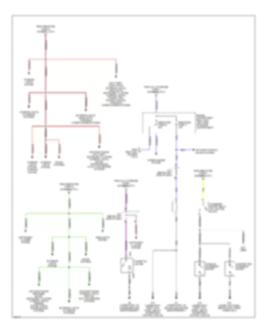
Power Distribution Wiring Diagram (2 of 3) for Mitsubishi Montero Limited 2004
List of elements for Power Distribution Wiring Diagram (2 of 3) for Mitsubishi Montero Limited 2004:
- Acc
- Air conditioning & anti-lock brakes systems
- Air conditioning system
- Air conditioning, anti-lock brakes, defogger, power tops & seats systems
- Anti-lock brakes system
- Anti-theft, mirrors & wiper/ washer systems
- D-208
- D-209
- D-210
- D-211
- D-221
- Dedicated fuse 17 10a
- Dedicated fuse 18 10a
- Dedicated fuse 20 20a
- Defogger relay
- Defogger system
- Engine compartment relay box (left side of engine compartment)
- Engine controls system
- Engine controls, starting/charging & transmissions systems
- Exterior lights system
- Exterior lights, headlights & wiper/ washer systems
- From front ecu (diagram 1 of 3)
- From fusible d link 2 (diagram 1 of 3)
- From fusible link 2 (diagram 1 of 3)
- From fusible link 3 (diagram 2 of 3)
- Fusible link 3 40a
- Ignition switch
- Junction block (behind lower left side of dash)
- Lock
- Multi- purpose fuse 1 15a
- Multi- purpose fuse 10 20a
- Multi- purpose fuse 11 30a
- Multi- purpose fuse 12 30a
- Multi- purpose fuse 4 15a
- Multi- purpose fuse 5 10a
- Multi- purpose fuse 6 10a
- Multi- purpose fuse 8 10a
- Off
- Red
- Seats system
- Start
- To cigarette lighter (diagram 3 of 3)
- To dedicated fuse 22 (diagram 3 of 3)
- To fuse 20 junction block (diagram 2 of 3)
- Warning & sound systems
Power Distribution Wiring Diagram (3 of 3) for Mitsubishi Montero Limited 2004
List of elements for Power Distribution Wiring Diagram (3 of 3) for Mitsubishi Montero Limited 2004:
- (+)
- (-)
- (not used)
- Accessory socket relay (on junction block)
- Air conditioning & sound systems
- Air conditioning, anti-theft, instrument cluster, interior lights, sound, transmissions, & anti-lock brakes systems
- Air conditioning, defogger, sound, instrument cluster, interior lights, mirrors, power tops & transmissions systems
- Air conditioning, interior lights, seats & anti-lock brakes systems
- Anti-theft, door locks, exterior lights, headlights, instrument cluster, interior lights, power tops, power windows, warning & wiper/washer systems
- Cigarette lighter
- Console accessory socket
- Dedicated fuse 17 10a
- Dedicated fuse 22 20a
- E-04
- E-05
- Engine compartment relay box (left side of engine compartment)
- Exterior lights & warning systems
- Exterior lights system
- Exterior lights, headlights, warning & wiper/washer systems
- From dedicated fuse 18 (diagram 1 of 3)
- From dedicated fuse 23 (diagram 1 of 3)
- From dedicated fuse 8 (diagram 1 of 3)
- From f front ecu (diagram 1 of 3)
- From multi-purpose fuse 1 (diagram 2 of 3)
- From multi-purpose fuse 4 (diagram 2 of 3)
- G12 (under right front kick panel, below powertrain control module)
- G15 (under trim panel, behind right rear wheelwell)
- G7 (under dash, on driver side center reinforcement)
- G8 (under dash, on passenger side reinforcement)
- Headlights system
- Instrument cluster system
- Interior lights & warning systems
- Interior lights system
- Interior lights system, warning system
- J/c 7 (behind left side of dash)
- Quarter trim accessory socket
- Sound systems
- Wiper/washer system
POWER DOOR LOCKS
Power Door Locks Wiring Diagram for Mitsubishi Montero Limited 2004
List of elements for Power Door Locks Wiring Diagram for Mitsubishi Montero Limited 2004:
- (in right rear door)
- Anti-theft system
- Back door lock actuator (in back door)
- Back door switch
- Computer data lines system
- D207
- D209
- D210
- D212
- D217
- D221
- D222
- D223
- D224
- Engine compartment relay box (left side of engine compt)
- Etacs-ecu
- Exterior lights system
- Fuse 18 15a
- G7 (under dash, on driver side center reinforcement)
- Horns system
- Hot at all times
- Hot in run or start
- Interior lights system
- Joint connector 6 (behind left side of dash)
- Joint connector 8 (behind left side of dash)
- Junction block (behind lower left side of dash)
- Key reminder switch
- Left door lock key cylinder switch (in left door)
- Left front door lock actuator (in left front door)
- Left front door switch
- Left rear door lock actuator (in left rear door)
- Left rear door switch
- Lock
- Multi- purpose fuse 6 10a
- Nca
- Off
- Off nca
- Power window main switch
- Red
- Red/
- Right door lock key cylinder switch (in right door)
- Right front door lock actuator (in right front door)
- Right front door switch
- Right front power window sub switch
- Right rear door lock actuator
- Right rear door switch
- Unlock
POWER MIRRORS
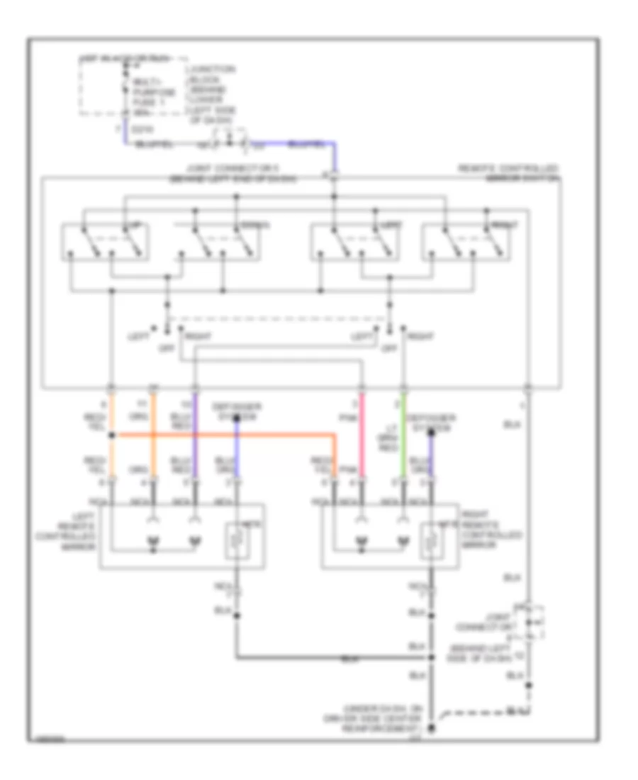
Power Mirrors Wiring Diagram for Mitsubishi Montero Limited 2004
List of elements for Power Mirrors Wiring Diagram for Mitsubishi Montero Limited 2004:
- (under dash, on driver side center reinforcement) g7
- D210
- Defogger system
- Down
- Hot in acc or run
- Htr
- Joint connector (behind left side of dash)
- Joint connector 5 (behind left end of dash)
- Junction block (behind lower left side of dash)
- Left
- Left remote controlled mirror
- Multi- purpose fuse 1 15a
- Nca
- Off
- Pnk
- Remote controlled mirror switch
- Right
- Right remote controlled mirror
POWER SEATS
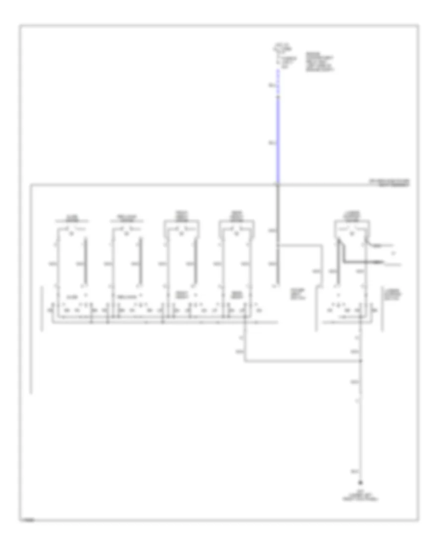
Driver Seat Wiring Diagram for Mitsubishi Montero Limited 2004
List of elements for Driver Seat Wiring Diagram for Mitsubishi Montero Limited 2004:
- Driver's side power seat assembly
- Engine compartment relay box (left side of engine compt)
- Front height
- Front height motor
- Fusible link 4 30a
- G10 (under left front kick panel)
- Hot at all times
- Lumbar support motor
- Lumbar support switch
- Nca
- Power seat switch
- Rear height
- Rear height motor
- Reclining
- Reclining motor
- Slide
- Slide motor
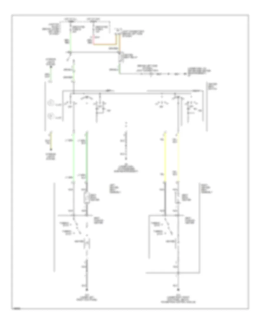
Heated Seats Wiring Diagram for Mitsubishi Montero Limited 2004
List of elements for Heated Seats Wiring Diagram for Mitsubishi Montero Limited 2004:
- (behind left side of dash) joint connector 8
- (under dash, on driver side center reinforcement) g7
- D210
- Dedicated fuse 20 20a
- Dedicated fuse 5 10a
- G10 (under left front kick panel)
- G12 (under right front kick panel, below powertrain control module)
- G8 (under dash, on passenger side reinforcement)
- Heated seat relay
- Heated seat switch
- Heater
- Hot at acc or on
- Hot at all times
- Illum
- Ind
- Interior lights system
- Joint connector 6 (behind left side of dash)
- Junction block (behind lower left side of dash)
- Left
- Left heated seat assembly
- Nca
- Off
- Right
- Right heated seat assembly
- Seat back heater
- Seat cushion heater
- Thermo- stat
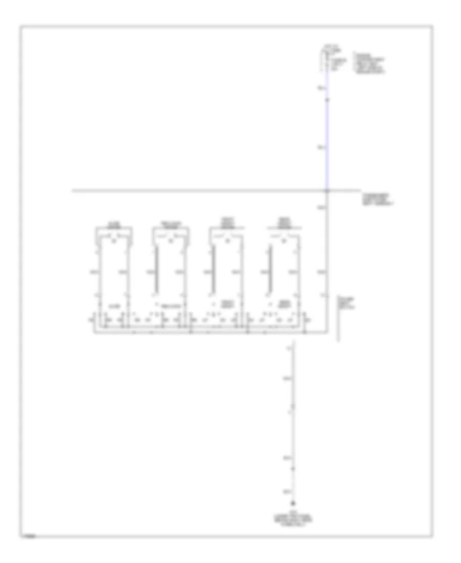
Passenger"s Power Seat Wiring Diagram for Mitsubishi Montero Limited 2004
List of elements for Passenger"s Power Seat Wiring Diagram for Mitsubishi Montero Limited 2004:
- Engine compartment relay box (left side of engine compt)
- Front height
- Front height motor
- Fusible link 4 30a
- G15 (under trim panel, behind right rear wheelwell)
- Hot at all times
- Nca
- Passenger's side power seat assembly
- Power seat switch
- Rear height
- Rear height motor
- Reclining
- Reclining motor
- Slide
- Slide motor
POWER TOP/SUNROOF
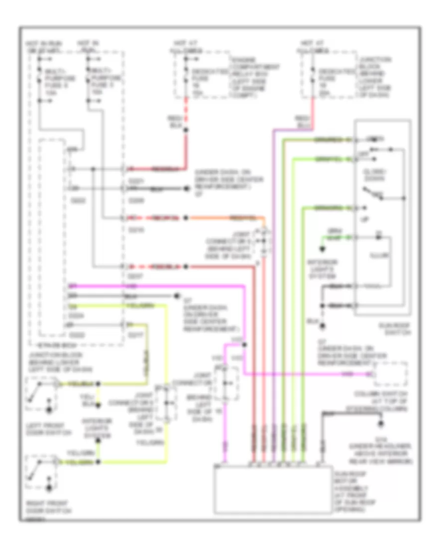
Power Top/Sunroof Wiring Diagram for Mitsubishi Montero Limited 2004
List of elements for Power Top/Sunroof Wiring Diagram for Mitsubishi Montero Limited 2004:
- (under dash, on driver side center reinforcement) g7
- Close/ down
- Column switch (at top of steering column)
- D207
- D209
- D210
- D217
- D221
- D222
- D224
- Dedicated fuse 15a
- Dedicated fuse 20a
- Engine compartment relay box (left side of engine compt)
- Etacs ecu
- G14 (under headliner, above interior
- G7 (under dash, on driver side center reinforcement)
- Hot at all times
- Hot in run
- Hot in run or start
- Illum
- Interior lights system
- Joint connector (behind left side of dash)
- Joint connector 6 (behind left side of dash)
- Junction block (behind lower left side of dash)
- Left front door switch
- Multi- purpose fuse 5 10a
- Multi- purpose fuse 6 10a
- Off
- Open
- Rear view mirror)
- Right front door switch
- Sun roof motor assembly (at front of sun roof opening)
- Sun roof switch
POWER WINDOWS
Power Windows Wiring Diagram for Mitsubishi Montero Limited 2004
List of elements for Power Windows Wiring Diagram for Mitsubishi Montero Limited 2004:
- D208
- D209
- D217
- D220
- D221
- D222
- D224
- Data link connector (lower left side of dash, right of steering column)
- Down
- Engine compartment relay box (left side of engine compt)
- Etacs-ecu
- Fuse 15a
- Fusible link 4 30a
- G7 (under dash, on driver side center reinforcement)
- Hot at all times
- Hot in on or start
- Illum
- Interior lights system
- Joint connector 6 (behind left side of dash)
- Junction block (behind lower left side of dash)
- Left front door switch
- Left front power window switch
- Left front power window motor
- Left rear power window switch
- Left rear power window motor
- Left rear power window sub switch
- Lock
- Lock switch
- Multi- purpose fuse 6 10a
- Nca
- Off
- Power window main switch
- Power window relay
- Red
- Right front door switch
- Right front power window switch
- Right front power window motor
- Right front power window sub switch
- Right rear power window switch
- Right rear power window motor
- Right rear power window sub switch
- Unlock
RADIO
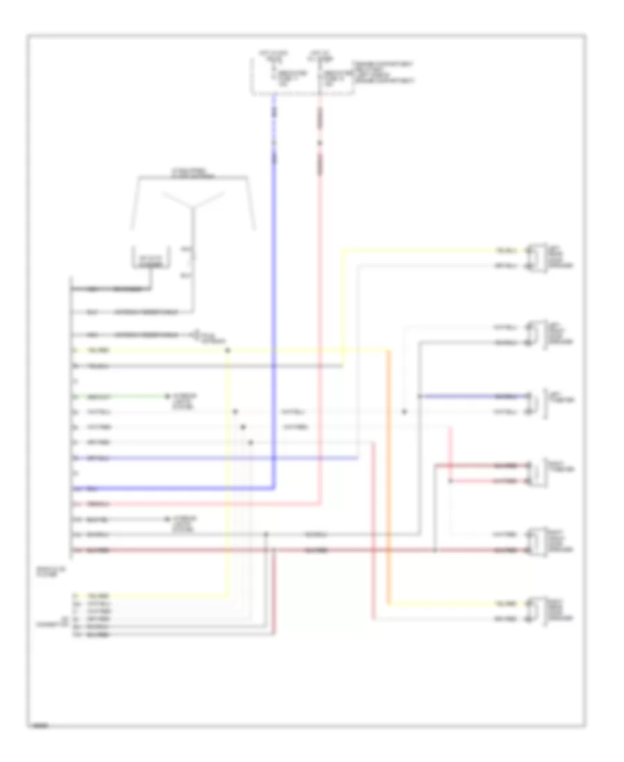
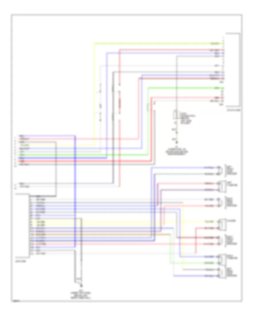
Radio Wiring Diagram, with Amplifier for Mitsubishi Montero Limited 2004
List of elements for Radio Wiring Diagram, with Amplifier for Mitsubishi Montero Limited 2004:
- Amplifier
- Antenna feeder cable
- Cd auto changer
- D210
- Dedicated fuse 17 10a
- Dedicated fuse 18 10a
- Din cable
- Engine compartment relay box (left side of engine compartment)
- Fusible link 29 20a
- G13 (under trim panel, behind left rear wheelwell)
- G7 (under dash, on driver side center reinforcement)
- Glass antenna
- Hot at all times
- Hot in acc or on
- Hot in on or start
- Instrument cluster system
- Interior lights system
- Joint connector 7 (behind left side of dash)
- Joint connector 8 (behind left side of dash)
- Junction block (behind lower left side of dash)
- Left front door speaker
- Left rear door speaker
- Left tweeter
- Motor antenna
- Motor antenna ecu (behind lower right side of dash)
- Multi-purpose fuse 6 10a
- Nca
- Pnk
- Radio & cd player
- Right front door speaker
- Right rear door speaker
- Right tweeter
- Woofer
Radio Wiring Diagram, without Amplifier for Mitsubishi Montero Limited 2004
List of elements for Radio Wiring Diagram, without Amplifier for Mitsubishi Montero Limited 2004:
- (if equipped) glass antenna
- Antenna feeder cable
- Cd auto changer
- Dedicated fuse 17 10a
- Dedicated fuse 18 15a
- Din cable
- Engine compartment relay box (left side of engine compartment)
- Hot at all times
- Hot in acc or on
- Interior lights system
- Left front door speaker
- Left rear door speaker
- Left tweeter
- Nca
- No connection
- Pole antenna
- Radio & cd player
- Right front door speaker
- Right rear door speaker
- Right tweeter
Video System Wiring Diagram (1 of 2) for Mitsubishi Montero Limited 2004
List of elements for Video System Wiring Diagram (1 of 2) for Mitsubishi Montero Limited 2004:
- Din cable
- Engine compartment relay box (left side of engine compartment)
- F32
- F33
- F34
- F35
- F36
- F37
- Fuse 17 10a
- Fuse 18 15a
- Fuse 23 10a
- Fusible link 29 20a
- G10 (under left front kick panel)
- Hot at all times
- Hot in acc or on
- Hot w/ taillight relay energized
- Interior lights system
- Joint connector 6 (behind left side of dash)
- Joint connector 7 (behind left side of dash)
- Nca
- Player
- Pnk
- Radio & cd
- Rear display
- Red
- Video controller unit (below driver's seat)
- Vtr adapter
Video System Wiring Diagram (2 of 2) for Mitsubishi Montero Limited 2004
List of elements for Video System Wiring Diagram (2 of 2) for Mitsubishi Montero Limited 2004:
- Amplifier
- D33
- D35
- Dvd player
- G13 (under trim panel, behind left rear wheelwell)
- G7 (under dash, on driver side center reinforcement)
- Joint connector 8 (behind left side of dash)
- Left front door speaker
- Left rear door speaker
- Left tweeter
- Nca
- Red
- Right front door speaker
- Right rear door speaker
- Right tweeter
- Woofer
STARTING/CHARGING
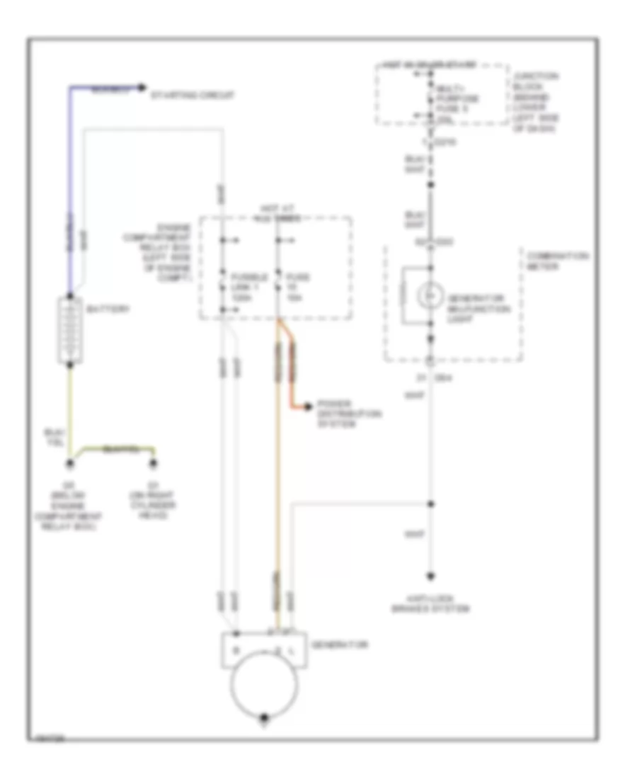
Charging Wiring Diagram for Mitsubishi Montero Limited 2004
List of elements for Charging Wiring Diagram for Mitsubishi Montero Limited 2004:
- Anti-lock brakes system
- Battery
- Combination meter
- D03
- D04
- D210
- Engine compartment relay box (left side of engine compt)
- Fuse 10a
- Fusible link 1 120a
- G1 (on right cylinder head)
- G5 (below engine compartment relay box)
- Generator
- Generator malfunction light
- Hot at all times
- Hot in on or start
- Junction block (behind lower left side of dash)
- Multi- purpose fuse 6 10a
- Power distribution system
- Starting circuit
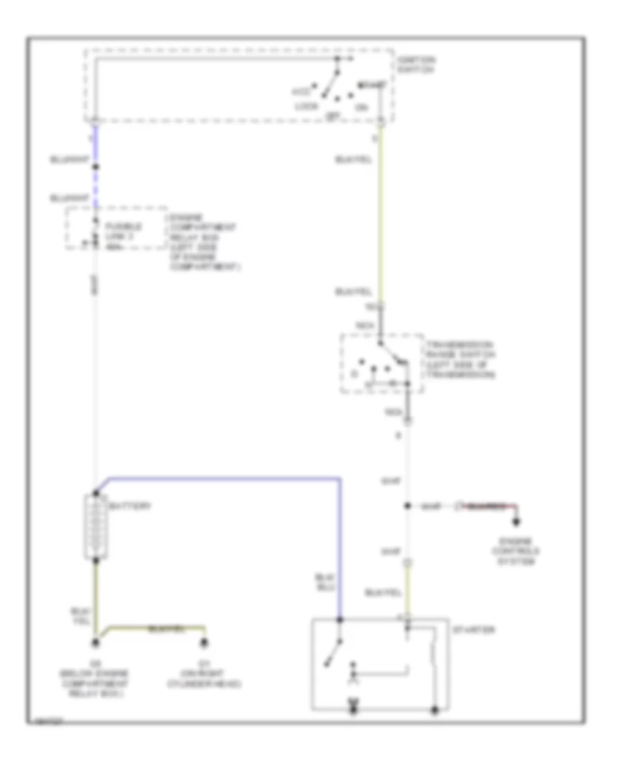
Starting Wiring Diagram for Mitsubishi Montero Limited 2004
List of elements for Starting Wiring Diagram for Mitsubishi Montero Limited 2004:
- Acc
- Battery
- Engine compartment relay box (left side of engine compartment)
- Engine controls system
- Fusible link 3 40a
- G1 (on right cylinder head)
- G5 (below engine compartment relay box)
- Ignition switch
- Lock
- Nca
- Off
- Start
- Starter
- Transmission range switch (left side of transmission)
SUPPLEMENTAL RESTRAINTS
Supplemental Restraints Wiring Diagram (1 of 2) for Mitsubishi Montero Limited 2004
List of elements for Supplemental Restraints Wiring Diagram (1 of 2) for Mitsubishi Montero Limited 2004:
- (at left front of engine compartment, next to radiator) left front impact sensor
- (at right front of engine compartment, next to radiator) right front impact sensor
- (in instrument panel harness, behind instrument cluster) s017
- (in instrument panel harness, behind left side of dash) s097
- (under dash, on driver side center reinforcement) g7
- (under dash, on passenger side reinforcement) g8
- Air bag drive circuit
- Clock spring
- Combination meter
- Connector lock switch (connector coupled: on) (connector uncoupled: off)
- D-03
- D-04
- D-209
- D-210
- Data
- Data link connector (partial) (lower left side of dash, right of steering column)
- Detection circuit
- Driver's side air bag module (squib)
- E-08
- Fuse 10a
- Ground
- Hot in on or start
- Ignition
- Interface
- J/c 5 (behind left end of dash)
- Junction block (behind lower side of dash)
- Nca
- Off
- Srs ecu (under front of center console)
- Srs indicator
- Warning light
Supplemental Restraints Wiring Diagram (2 of 2) for Mitsubishi Montero Limited 2004
List of elements for Supplemental Restraints Wiring Diagram (2 of 2) for Mitsubishi Montero Limited 2004:
- (connector coupled: on) (connector uncoupled: off) connector lock switch
- Air bag drive circuit
- Connector lock switch (connector coupled: on) (connector uncoupled: off)
- E-07
- Ground
- Interface
- Left seat belt pretensioner
- Left side air bag module squib
- Left side impact sensor (at base of left "b" pillar)
- Nca
- Off
- Passenger's side air bag module squib
- Red
- Right seat belt pretensioner
- Right side air bag module (squib)
- Right side impact sensor (at base of right "b" pillar)
- Solid state
- Srs ecu (under front of center console)
TRANSMISSION
4WD Wiring Diagram for Mitsubishi Montero Limited 2004
List of elements for 4WD Wiring Diagram for Mitsubishi Montero Limited 2004:
- (behind center of dash) astc ecu
- (not used)
- (on transfer case) front propeller shaft speed sensor
- (on transfer case) shift actuator
- (right front corner of engine compt)
- 2wd
- 2wd/4wd
- 4hlc
- 4llc
- A/t circuit
- Anti-lock brakes system
- C/d lock
- Center differential lock
- Combination meter
- D-03
- D-04
- D-210
- D-212
- D-220
- D-32
- Data link connector (left side of dash, right
- Detection switches (on transfer case)
- Diode (4wd) (at left kick panel)
- E-104
- E-109
- Engine compartment relay box (left side of engine compt)
- Engine controls system (app)
- Free- wheeling engage switch (near generator)
- Frt lh
- Frt rh
- Fuse 10a
- Fuse 15a
- G16 (under center console)
- G3 (rear of left front fender)
- Hot at all times
- Hot in run or start
- Interior lights system
- J/c 2 (left side of engine compt)
- J/c 3 (left side of engine compt)
- J/c 4 (behind right side of dash)
- J/c 5 (left end of dash)
- J/c 6 (behind left side of dash)
- J/c 7 (behind left side of dash)
- Junction block (behind left side of dash)
- Of steering column)
- Rear lh
- Rear propeller shaft speed sensor (on transfer case)
- Rear rh
- Red
- Solenoid valve a
- Solenoid valve b
- Stoplight switch (above brake pedal)
- Tone alarm (below center of dash)
- Transfer ecu (behind center of dash)
- Transfer shift lever switch (below center console)
- Transmission range switch (on trans)
A/T Wiring Diagram for Mitsubishi Montero Limited 2004
List of elements for A/T Wiring Diagram for Mitsubishi Montero Limited 2004:
- (left side of transmission) input shaft speed sensor
- (lower left side of dash) data link connector
- (right kick panel)
- 1 ind
- 2 ind
- 3 ind
- 4 ind
- 4llc detection switch (on transfer case)
- 4wd circuit (awd)
- 5 ind
- A/t control relay (behind right side of dash)
- A/t control solenoid valve assembly
- A/t oil temp
- Accelerator pedal position sensor
- At tmp
- Auto
- Combination meter
- D ind
- D-03
- D-04
- D-117
- D-133
- D-134
- D-135
- D-136
- D-212
- D-32
- Engine compartment relay box (left side of engine compt)
- Engine controls system
- Engine coolant temperature sensor (top front of engine)
- Exterior lights & wiper/washer systems
- Fuse 10a
- Fuse 15a
- Fuse 20a
- Fuse link 5 20a
- G16 (under center console)
- G7 (behind left center of dash)
- Hot at all times
- Hot in run or start
- J/c 4 (behind right side of dash)
- J/c 4 (right side of dash)
- J/c 5 (left side of dash)
- J/c 8 (left side of dash)
- Junction block (behind left side of dash)
- Low/ reverse
- N ind
- Output shaft speed sensor (right side of transmission)
- Over drive
- P ind
- Pnk
- Powertrain control module (behind right side of dash)
- R ind
- Red
- Reduc- tion
- Second
- Shift switch assembly
- Sport
- Starting/ charging system
- Stoplight switch (above brake pedal)
- Tcc
- Throttle actuator control motor relay
- Transmission range switch (on top of transmission)
- Under drive
- Vehicle speed sensor (top of transfer case rear cover)
WARNING SYSTEMS
Chime Wiring Diagram for Mitsubishi Montero Limited 2004
List of elements for Chime Wiring Diagram for Mitsubishi Montero Limited 2004:
- (lower left side of dash, right of steering column)
- Column ecu
- Column switch (at top of steering column)
- Combination meter
- D03
- D04
- D209
- D210
- D217
- D220
- D221
- D222
- D224
- D32
- Data link connector
- Dedicated fuse 18 15a
- Door ind
- Engine compartment relay box (left side of engine compt)
- Etacs ecu
- G10 (under left front kick panel)
- G7 (under dash, on driver side center reinforcement)
- Headlights system
- Hot at all times
- Hot in run or start
- Interior lights system
- Joint connector 6 (behind left side of dash)
- Joint connector 8 (behind left side of dash)
- Junction block (behind lower left side of dash)
- Key reminder switch
- Left front door switch
- Multi- purpose fuse 6 10a
- Nca
- Pnk
- Seat belt ind
- Seat belt switch
Tire Pressure Monitoring Wiring Diagram for Mitsubishi Montero Limited 2004
List of elements for Tire Pressure Monitoring Wiring Diagram for Mitsubishi Montero Limited 2004:
- Antenna
- Anti-lock brakes system
- Combination meter
- Connector 4
- Connector 5 (behind left end of dash)
- Connector 7 (behind left side of dash)
- Control circuit
- D03
- D04
- D210
- D212
- D220
- Data link connector (lower left side of dash, right of steering column)
- Engine compartment relay box (left side of engine compt)
- Feeder cable
- Fuse 18 15a
- Fuse 6 10a
- G15 (under trim panel, behind right rear wheelwell)
- G16 (under rear of center console)
- G28
- G28-1
- G28-3
- G28-4
- G28-5
- Hot at all times
- Hot in run or start
- Instrument cluster system
- Joint
- Junction block (behind lower left side of dash)
- Left front tpms antenna
- Left rear tpms antenna
- Right front tpms antenna
- Right rear tpms antenna
- Tpms ind
- Tpms receiver (left center of vehicle)
- Vehicle speed sensor (on top of transfer case rear cover)
WIPER/WASHER
Front Wiper/Washer Wiring Diagram for Mitsubishi Montero Limited 2004
List of elements for Front Wiper/Washer Wiring Diagram for Mitsubishi Montero Limited 2004:
- (hi)
- (int)
- (lo)
- (mist)
- A07x
- A08x
- Air conditioning system
- All times
- Circuit breaker
- Column ecu
- Column switch (at top of steering column)
- Computer data lines system
- D209
- D210
- D221
- D222
- D224
- Dedicated fuse 18 15a
- Dedicated fuse 22 20a
- Engine compartment relay box (left side of engine compartment)
- Etacs ecu
- Fast
- Front ecu
- G3 (at left rear of engine compartment)
- G6 (at left front of engine compartment, between relay box & fender panel)
- G7 (under dash, on driver side center reinforcement)
- G7 (under dash, on driver side center reinforcement)
- Gnd
- Ground
- Hot at
- Hot in on
- Joint connector (behind left side of dash)
- Junction block (behind lower left side of dash)
- Multi- purpose fuse 1 15a
- Multi- purpose fuse 5 10a
- Multi- purpose fuse 6 10a
- Nca
- Off
- Or acc
- Or start
- Pnk
- Slow
- Wind- shield washer relay
- Wind- shield washer switch
- Wind- shield wiper switch
- Windshield intermittent wiper interval adjusting knob
- Windshield washer motor (behind right headlight)
- Windshield wiper motor (left rear of engine compartment)
- Wiper auto- matic stop relay
- Wiper speed switching relay
Rear Wiper/Washer Wiring Diagram for Mitsubishi Montero Limited 2004
List of elements for Rear Wiper/Washer Wiring Diagram for Mitsubishi Montero Limited 2004:
- Column ecu
- Column switch (at top of steering column)
- Computer data lines system
- D08
- D209
- D210
- D212
- D217
- D221
- D222
- D224
- Dedicated fuse 18 15a
- Engine compartment relay box (left side of engine compartment)
- Etacs ecu
- Exterior lights system
- G17 (under trim panel, on right side of tailgate)
- G7 (under dash, on driver side center reinforcement)
- Ground
- Hot at all times
- Hot in on or acc
- Hot in on or start
- Joint connector 4
- Joint connector 6 (behind left side of dash)
- Joint connector 7 (behind left side of dash)
- Junction block (behind lower left side of dash)
- Multi- purpose fuse 1 15a
- Multi- purpose fuse 6 10a
- Multi- purpose fuse 8 10a
- Nca
- Off
- Pnk
- Rear washer motor (in back door)
- Rear washer relay
- Rear washer switch
- Rear wiper motor (in back door)
- Rear wiper relay
- Rear wiper switch
- Rv meter
- Transmission range switch (left side of p transmission)
- Transmissions system

 Čeština
 Dansk
Dansk Deutsch
 Ελληνικά
 English
 English
 Español
 Suomi
Suomi Français
 Français
 עברית
עברית Hrvatski
 Magyar
 Italiano
 日本語
日本語 한국어
한국어 Nederlands
 Polski
 Português
 Português
 Română
 Русский
 Slovenščina
 Svenska
 Türkçe
 中文 (中国)