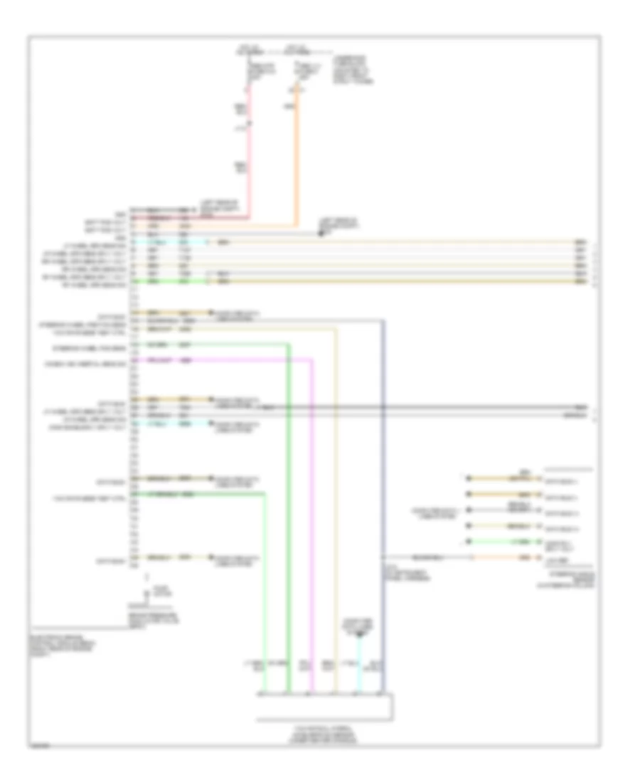
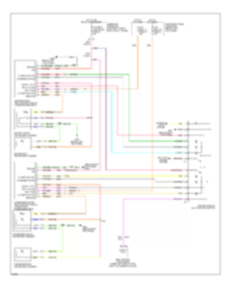
AIR CONDITIONING
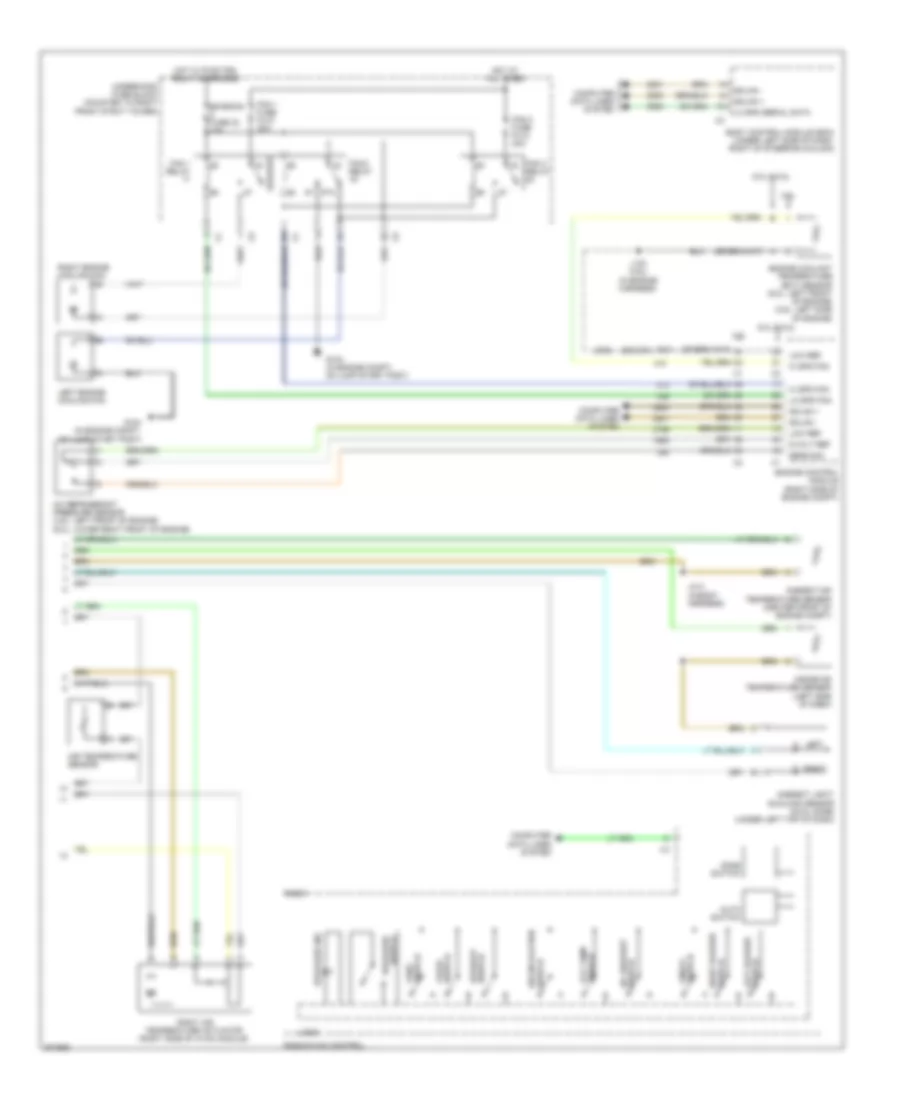
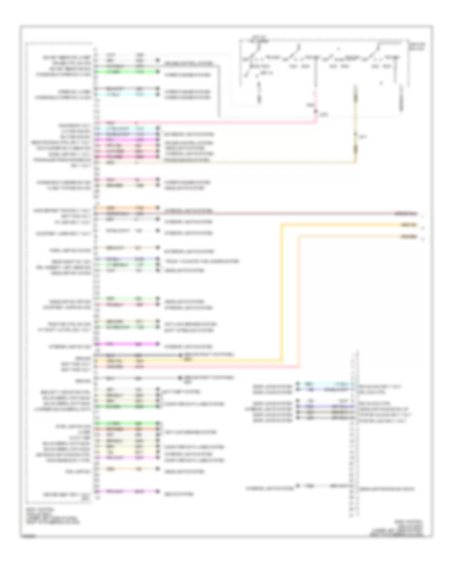
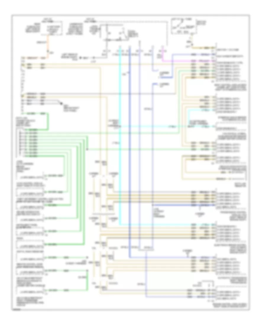
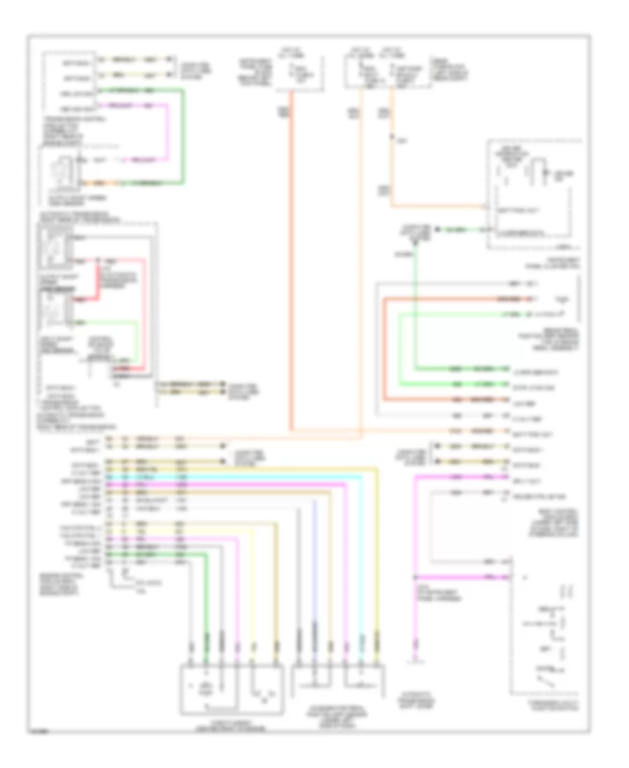
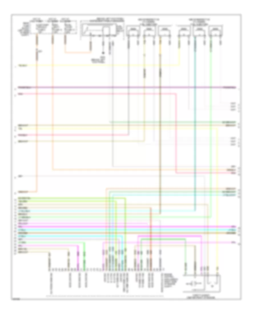
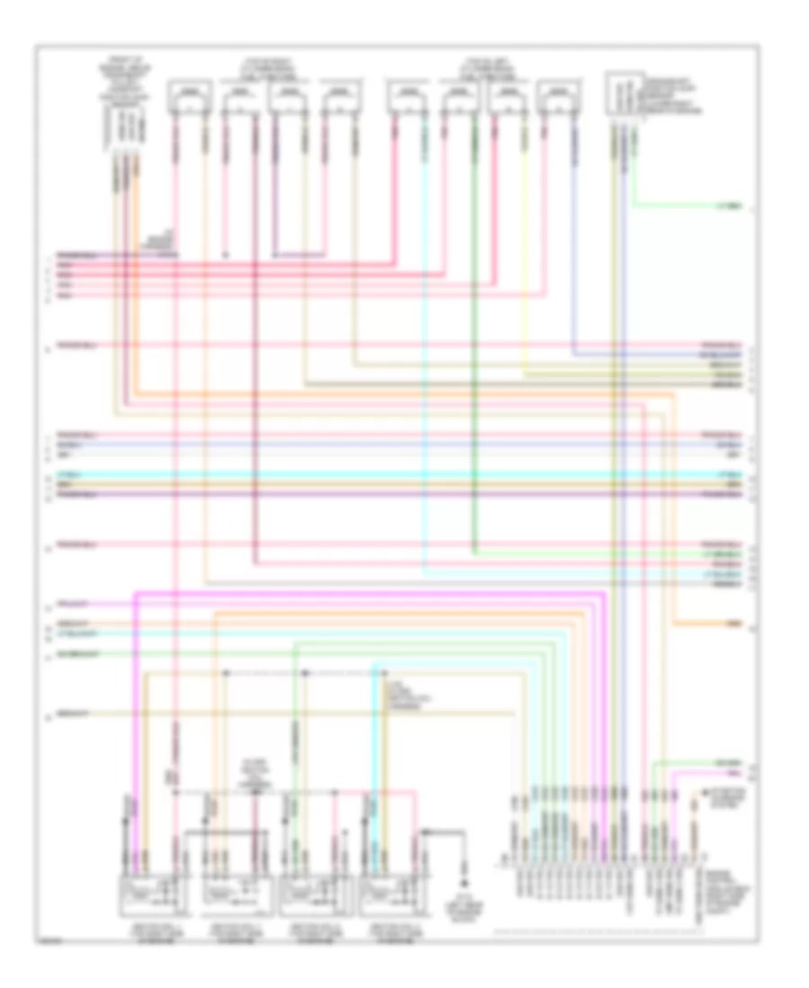
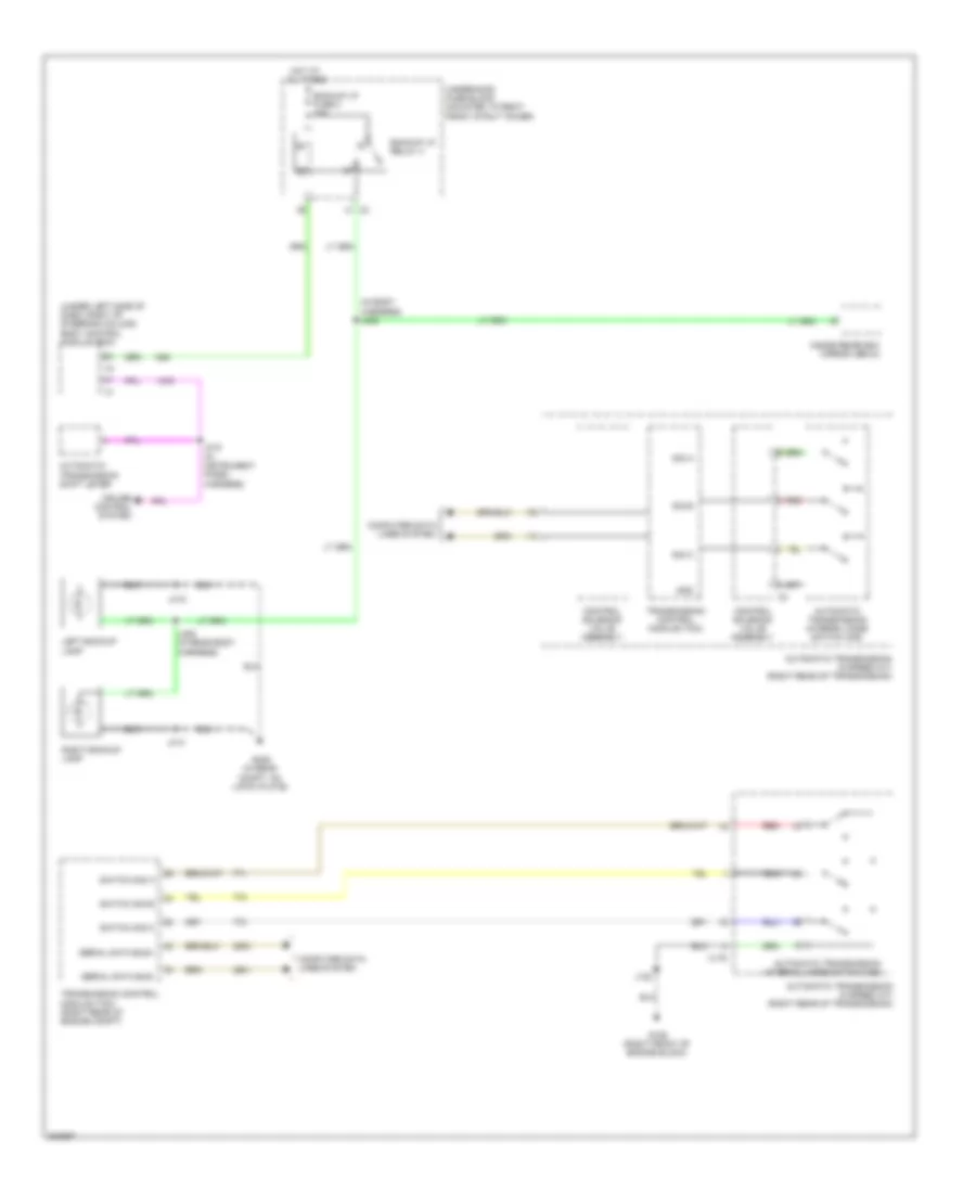
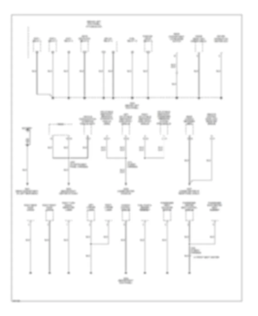
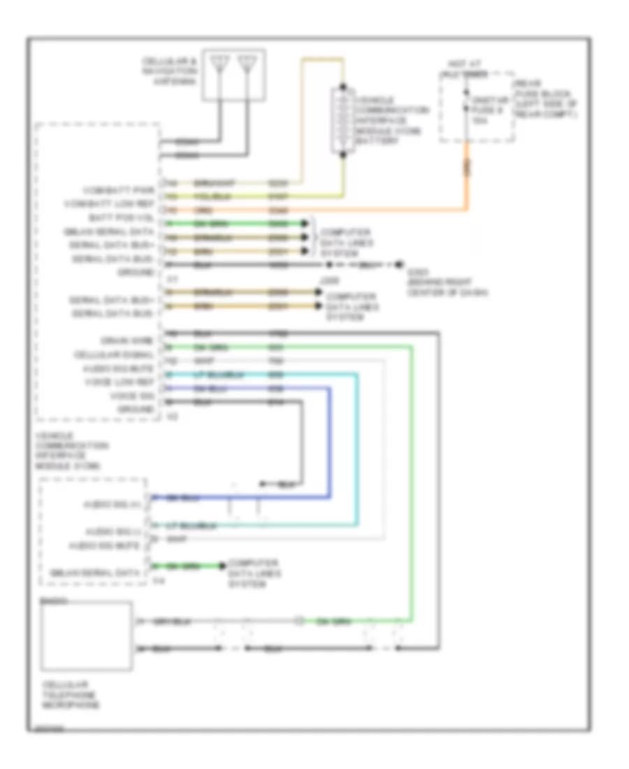
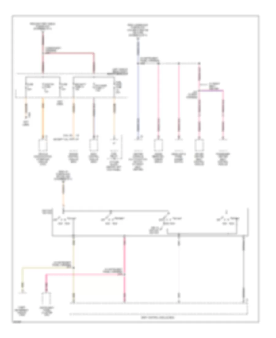
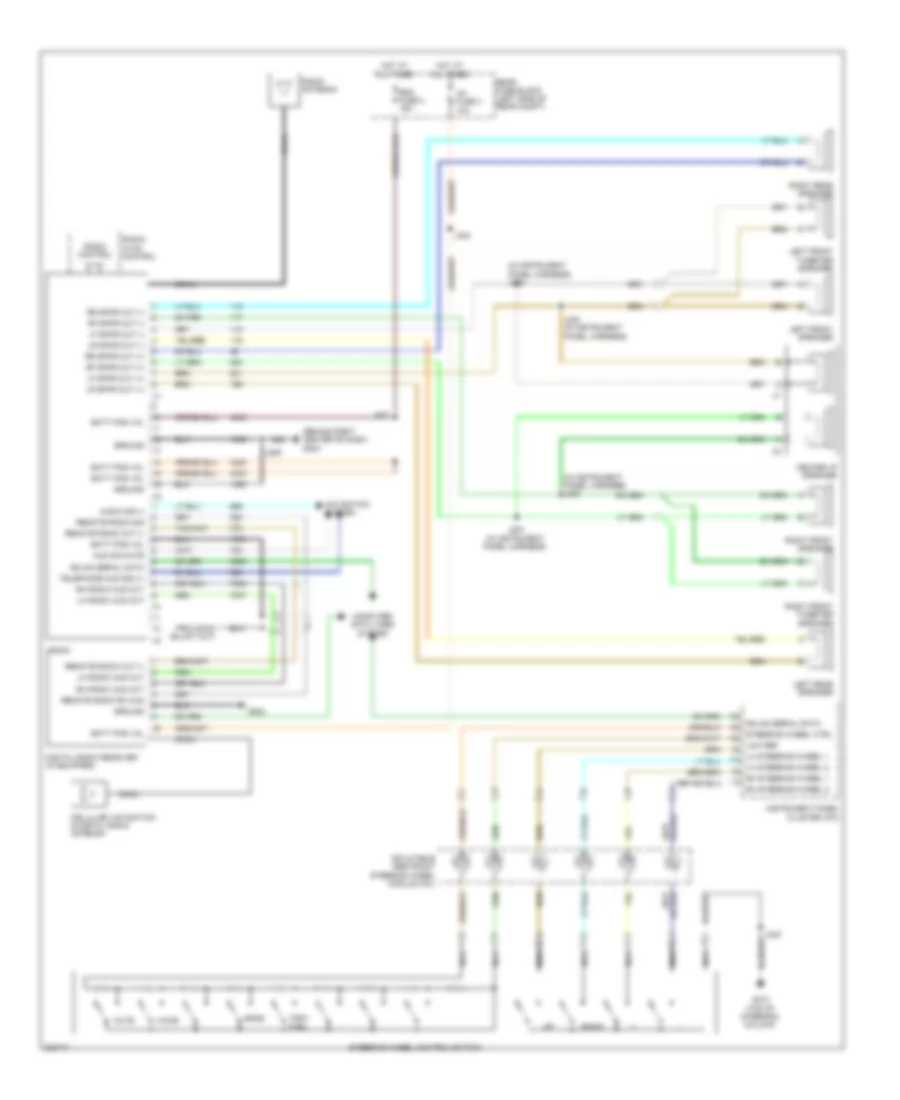
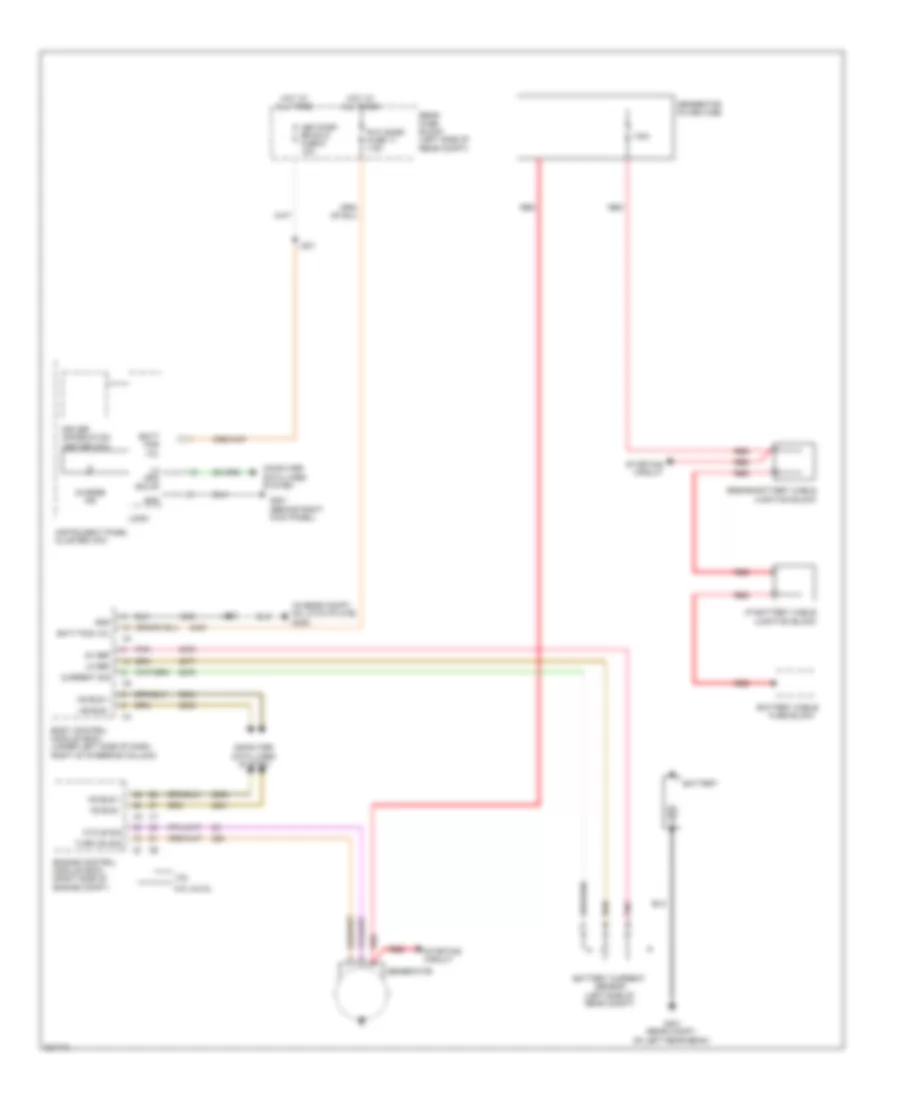
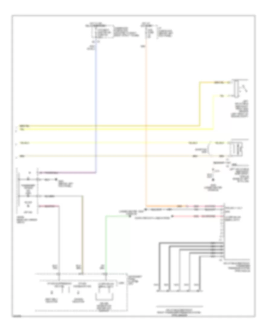
Automatic A/C Wiring Diagram (1 of 2) for Pontiac G8 GT 2009
 https://portal-diagnostov.com/license.html
Automotive Electricians Portal FZCO
Automotive Electricians Portal FZCO
https://portal-diagnostov.com/license.html
https://portal-diagnostov.com/license.html
Automotive Electricians Portal FZCO
Automotive Electricians Portal FZCO
List of elements for Automatic A/C Wiring Diagram (1 of 2) for Pontiac G8 GT 2009:
- (behind right kick panel) g201
- (in hvac harness) j242
- (in instrument panel harness) j200
- (right side of hvac unit) blower motor
- 5 volt ref
- A/c compressor clutch
- Air temp door ctrl
- Air temp door ctrl b
- Air temperature door ctrl
- Ambient air temp sen sig
- Auxiliary air temp door ctrl
- Auxiliary air temp door position sig
- Auxiliary mode actuator (left side of hvac module)
- Auxiliary mode door ctrl
- Battery positive volt
- Blower control module (under right side of dash)
- Blwr mtr speed ctrl
- Blwr mtr sply volt
- Blwr relay 9
- Computer data lines system
- Defogger system
- Front pass air temp motor ctrl
- G201 (behind right kick panel)
- Gnd
- Hot at all times
- Hot w/ ign relay 14 energized
- Hvac batt fuse 2 10a
- Hvac blwr fuse fu9 40a
- Hvac control module (right side of hvac unit)
- Hvac ign fuse 37 10a
- Ign 1 volt
- Inside air temp sen sig
- Inside air temp sensor motor ctrl
- Instrument panel fuse block (behind left kick panel)
- J223
- J241 (in hvac harness)
- Left air temperature actuator
- Left solar sen
- Logic
- Low ref
- Low speed gmlan serial data
- Lower mode door position sig
- Mode actuator (left side of hvac module)
- Mode door control a
- Mode door control b
- Mode door position sig
- Pnk
- Rear defog rly ctrl
- Recirculation actuator (top center of hvac unit)
- Recirculation door ctrl a
- Recirculation door ctrl b
- Recirculation door position sig
- Red
- Right solar sen
- Spd ctrl
- Sply volt
- Underhood fuse block (mounted to right front strut tower)
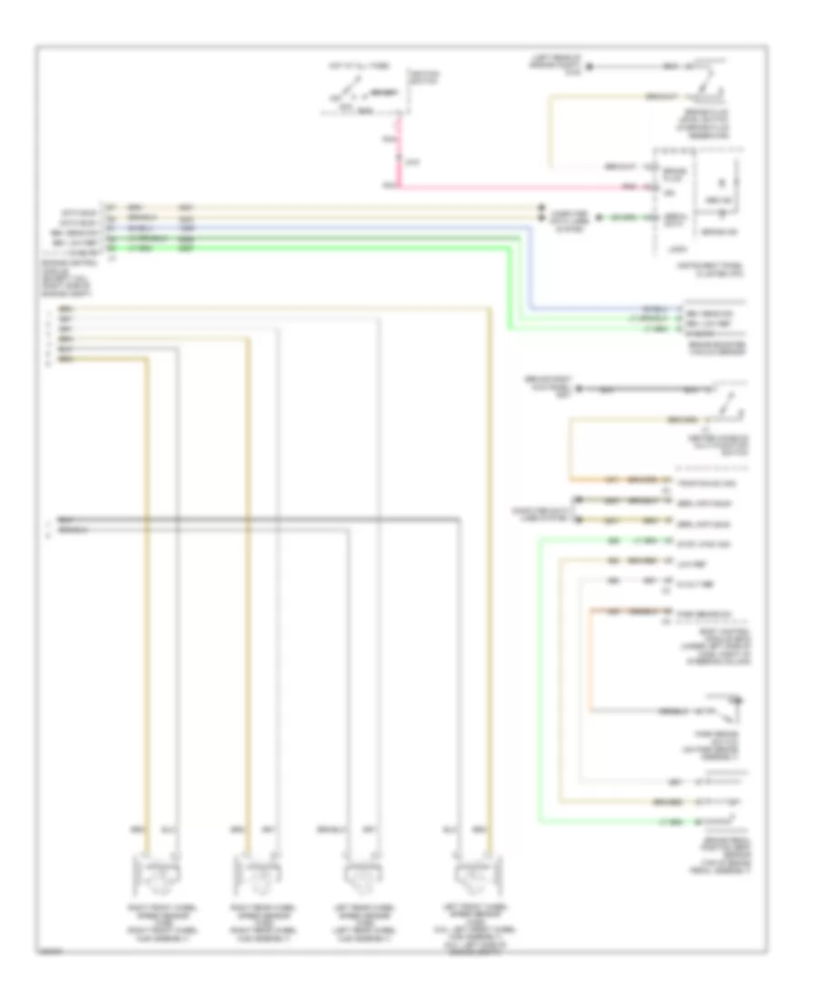
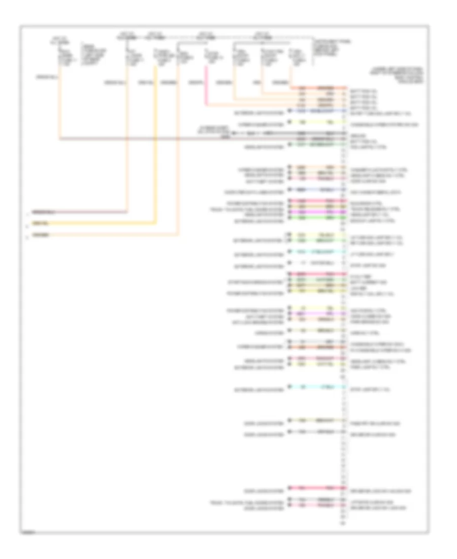
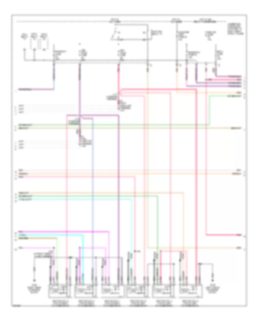
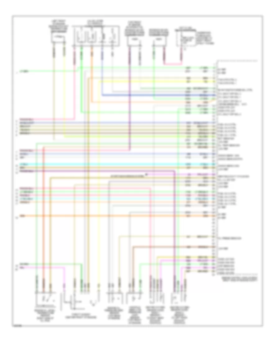
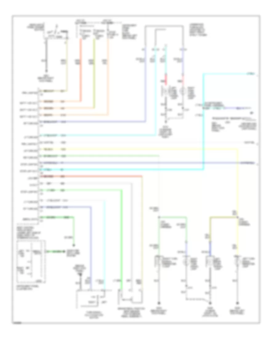
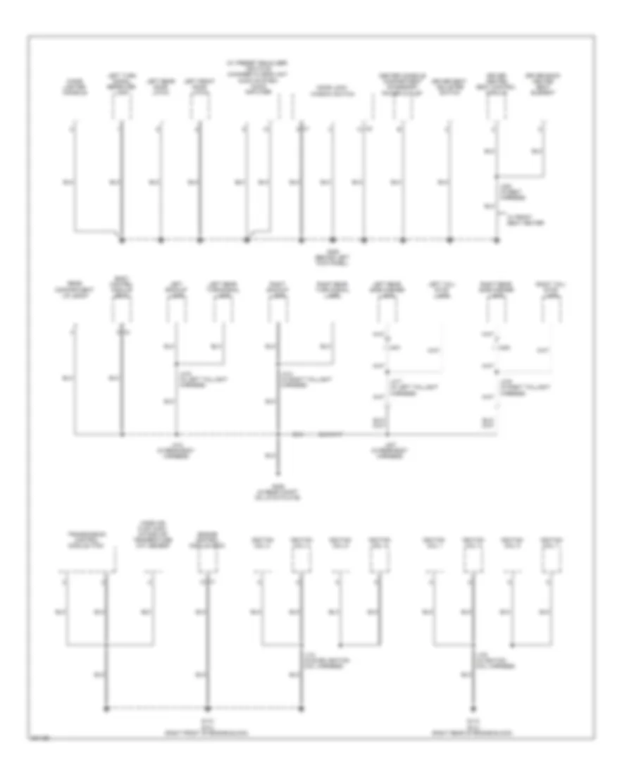
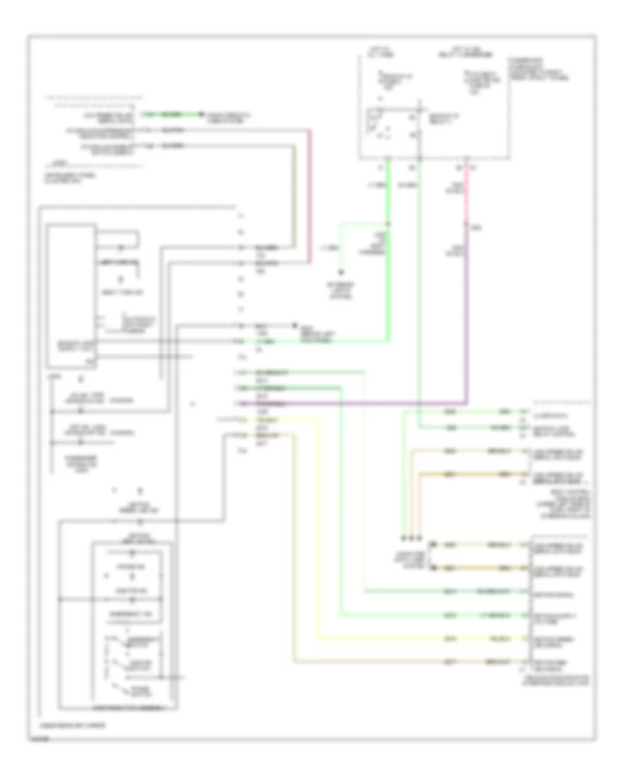
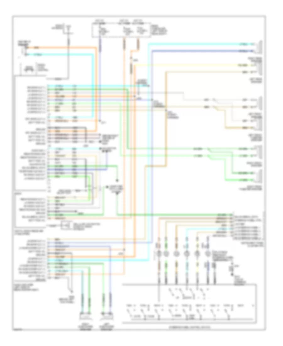
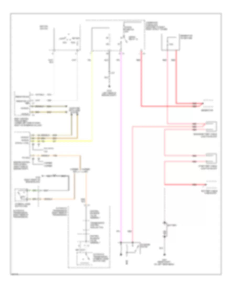
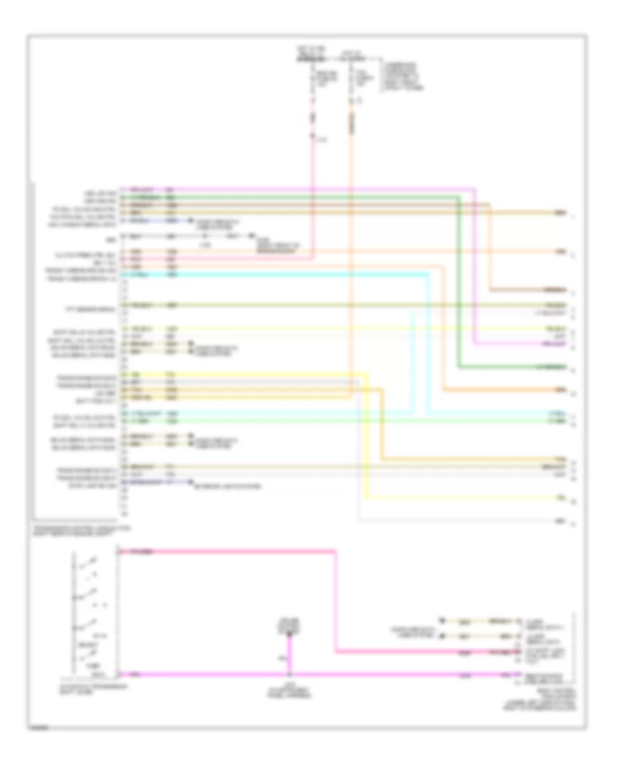
Automatic A/C Wiring Diagram (2 of 2) for Pontiac G8 GT 2009
List of elements for Automatic A/C Wiring Diagram (2 of 2) for Pontiac G8 GT 2009:
- (or 2761)
- 3.6l
- 5-volt ref
- 6.0l & 6.2l
- 87a
- A/c refrigerant pressure sensor (3.6l: left front of engine) (6.0l: lower right front of engine)
- Air temperature sensor
- Ambient air temperature sensor (center front of engine compt)
- Ambient light/ sunload sensor (dual zone) (under left top of dash)
- Auto switch
- Body control module (bcm) (under left side of dash, right of steering column)
- Computer data lines system
- Defogger ind
- Emission fuse 32 15a
- Engine control module (right side of engine compt)
- Engine coolant temperature (ect) sensor (6.0l: left front of engine) (3.6l: left side of engine)
- Fan 1 fuse fu10 30a
- Fan 1 relay
- Fan 2 fuse fu12 30a
- Fan 2 relay
- Fan 3 relay
- G104 (in engine compt, on jump start post)
- Gmlan +
- Gmlan -
- Hi spd fan
- Hot at all times
- Hot w/ pwr trn relay energized
- Inside air temperature sensor (left side of dash)
- J123 (3.6l) (in engine harness)
- J314 (in body harness)
- Left
- Left engine cooling fan
- Lo spd fan
- Lo spd serial data
- Logic
- Low ref
- Radio
- Radio/hvac control
- Right
- Right air temperature actuator (right side of hvac module)
- Right engine cooling fan
- Sens sig
- Switch a/c request
- Switch defogger
- Switch defrost
- Switch ext temp
- Switch floor
- Switch left blower
- Switch on/off
- Switch recirculation
- Switch right blower
- Switch vent
- Underhood fuse block (mounted to right front strut tower)
- Zone switch
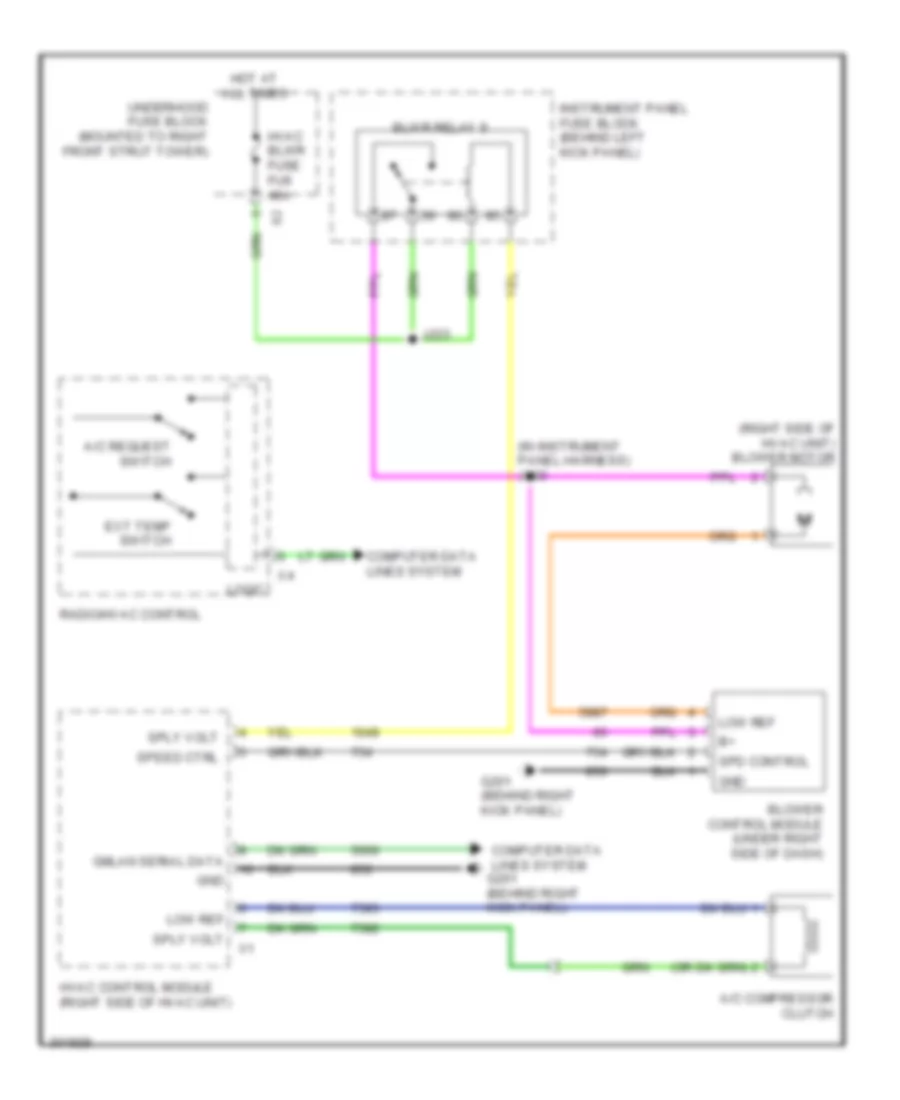
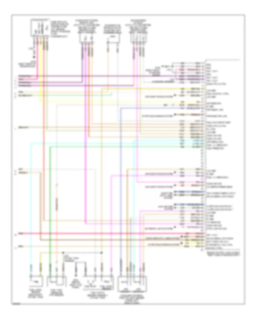
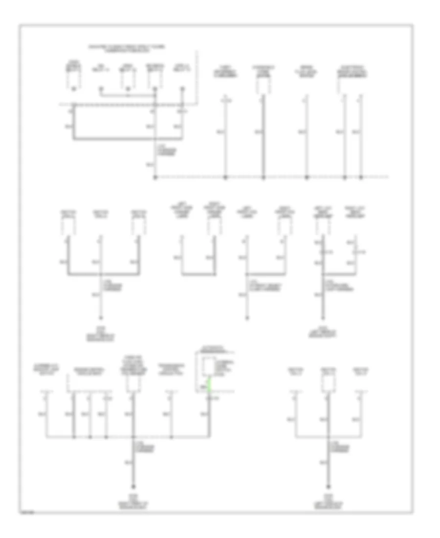
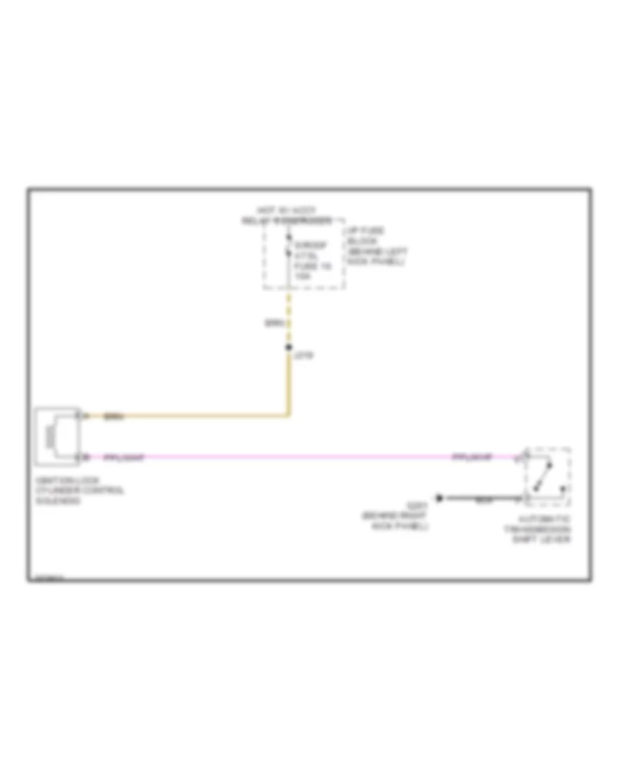
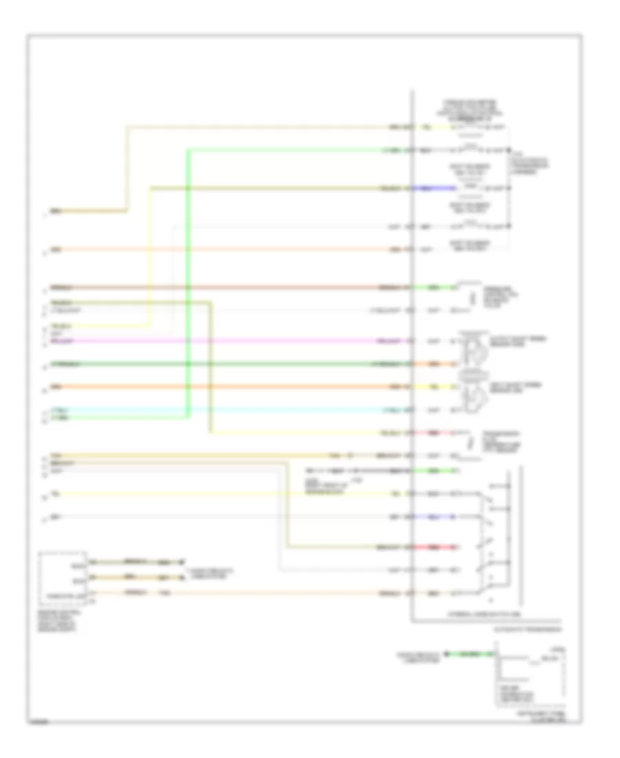
Compressor Wiring Diagram for Pontiac G8 GT 2009
List of elements for Compressor Wiring Diagram for Pontiac G8 GT 2009:
- (in instrument panel harness) j200
- (right side of hvac unit) blower motor
- A/c compressor clutch
- A/c request switch
- Blower control module (under right side of dash)
- Blwr relay 9
- Computer data lines system
- Computer data lines system g201 (behind right kick panel)
- Ext temp switch
- G201 (behind right kick panel)
- Gmlan serial data
- Gnd
- Hot at all times
- Hvac blwr fuse fu9 40a
- Hvac control module (right side of hvac unit)
- Instrument panel fuse block (behind left kick panel)
- J223
- Logic
- Low ref
- Radio/hvac control
- Spd control
- Speed ctrl
- Sply volt
- Underhood fuse block (mounted to right front strut tower)
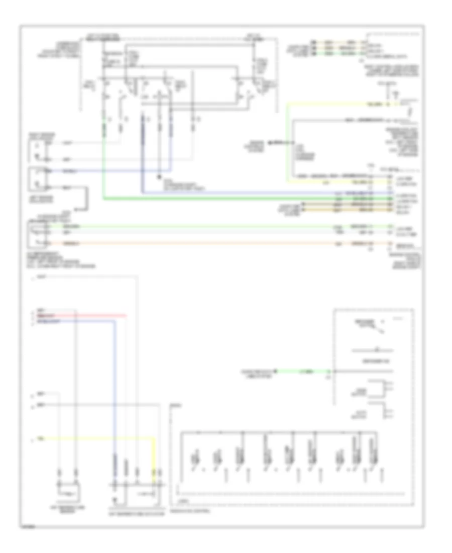
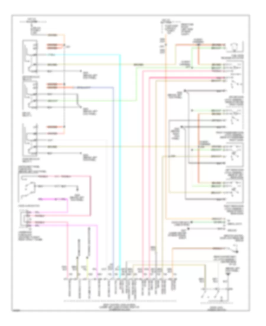
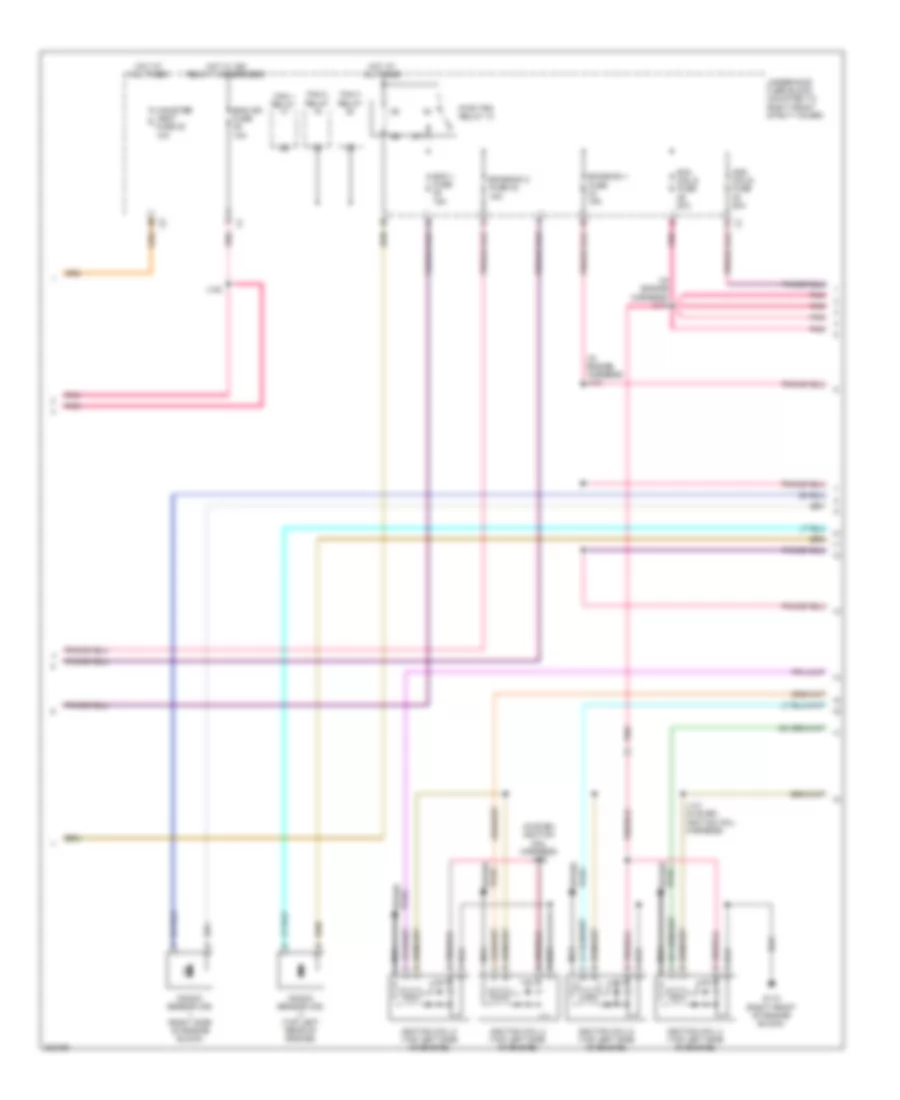
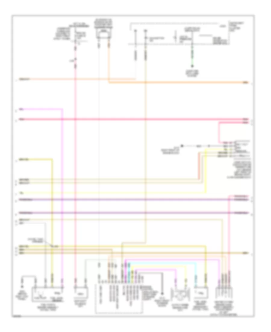
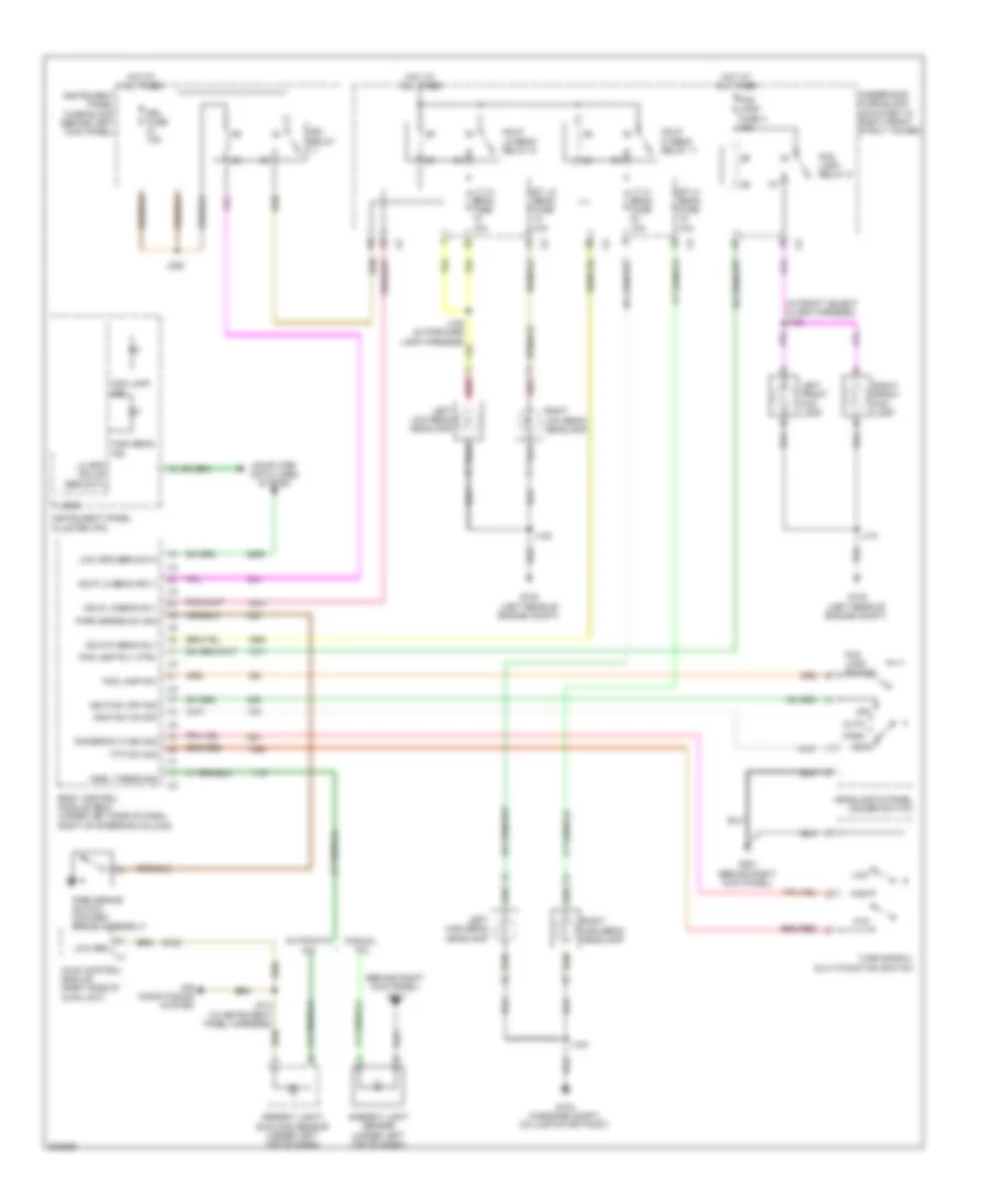
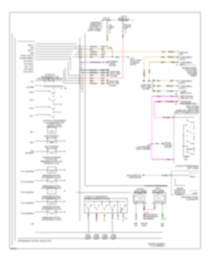
Manual A/C Wiring Diagram (1 of 2) for Pontiac G8 GT 2009
List of elements for Manual A/C Wiring Diagram (1 of 2) for Pontiac G8 GT 2009:
- (in hvac harness) j242
- (in instrument panel harness) j200
- (right side of hvac unit) blower motor
- 5 volt ref
- A/c compressor clutch
- Air temp door ctrl
- Air temp door ctrl b
- Air temperature door ctrl
- Auxiliary mode actuator (left side of hvac module)
- Auxiliary mode door ctrl
- Battery positive volt
- Blower control module (under right side of dash)
- Blwr mtr low ref
- Blwr mtr speed ctrl
- Blwr relay 9
- Computer data lines system
- Defogger system
- G201 (behind right kick panel)
- Gnd
- Hot at all times
- Hot w/ ign relay 14 energized
- Hvac batt fuse 2 10a
- Hvac blwr fuse fu9 40a
- Hvac control module (right side of hvac unit)
- Hvac ign fuse 37 10a
- Ign 1 volt
- Inside air temp sensor motor ctrl
- Instrument panel fuse block (behind left kick panel)
- J223
- J241 (in hvac harness)
- Logic
- Low ref
- Low speed gmlan serial data
- Lower mode door position sig
- Mode actuator (left side of hvac module)
- Mode door control a
- Mode door control b
- Mode door position sig
- Pnk
- Rear defog rly ctrl
- Recirculation actuator (top center of hvac unit)
- Recirculation door ctrl a
- Recirculation door ctrl b
- Recirculation door position sig
- Red
- Spd ctrl
- Sply volt
- Underhood fuse block (mounted to right front strut tower)
Manual A/C Wiring Diagram (2 of 2) for Pontiac G8 GT 2009
List of elements for Manual A/C Wiring Diagram (2 of 2) for Pontiac G8 GT 2009:
- (or 2761)
- 3.6l
- 5-volt ref
- 6.0l & 6.2l
- 87a
- A/c refrigerant pressure sensor (3.6l: left front of engine) (6.0l: lower right front of engine)
- Air temperature actuator
- Air temperature sensor
- Auto switch
- Body control module (bcm) (under left side of dash, right of steering column)
- Computer data lines system
- Defogger ind
- Defogger switch
- Emission fuse 32 15a
- Engine control module (right side of engine compt)
- Engine controls system
- Engine coolant temperature (ect) sensor (6.0l: left front of engine) (3.6l: left side of engine)
- Fan 1 fuse fu10 30a
- Fan 1 relay
- Fan 2 fuse fu12 30a
- Fan 2 relay
- Fan 3 relay
- G104 (in engine compt, on jump start post)
- Gmlan +
- Gmlan -
- Hi spd fan
- Hot at all times
- Hot w/ pwr trn relay energized
- J123 (3.6l) (in engine harness)
- Left engine cooling fan
- Lo spd fan
- Lo spd serial data
- Logic
- Low ref
- Radio
- Radio/hvac control
- Right engine cooling fan
- Sens sig
- Switch a/c request
- Switch defrost
- Switch ext temp
- Switch floor
- Switch left blower
- Switch on/off
- Switch recirculation
- Switch right blower
- Switch vent
- Underhood fuse block (mounted to right front strut tower)
- Zone switch
ANTI-LOCK BRAKES
Anti-lock Brakes Wiring Diagram (1 of 2) for Pontiac G8 GT 2009
List of elements for Anti-lock Brakes Wiring Diagram (1 of 2) for Pontiac G8 GT 2009:
- (left rear of engine compt) g102
- Abs mtr fuse fu3 40a
- Abs vlv fuse 5 25a
- Batt pos volt
- Brake pressure modulator valve (bpmv)
- Combin veh inertial sens sig
- Comm enable rly sply volt
- Comm rly sply volt
- Computer data lines system
- Data bus (+)
- Data bus (-)
- Data bus+
- Data bus-
- Electronic brake control module (ebcm) (right rear of engine compt)
- Gnd
- Hot at all times
- J112
- J212 (in instrument panel harness)
- Lf wheel spd sens sig
- Lf wheel spd sens sply volt
- Low ref
- Lr wheel spd sens sig
- Lr wheel spd sens sply volt
- Pump motor
- Rf wheel spd sens sig
- Rf wheel spd sens sply volt
- Rr wheel spd sens sig
- Rr wheel spd sens sply volt
- Steering angle sensor (in steering column)
- Steering wheel pos sens
- Steering wheel position sens
- Underhood fuse block (mounted to right front strut tower)
- Yaw rate & lateral acceleration sensor (under center console)
- Yaw rate sens test ctrl
Anti-lock Brakes Wiring Diagram (2 of 2) for Pontiac G8 GT 2009
List of elements for Anti-lock Brakes Wiring Diagram (2 of 2) for Pontiac G8 GT 2009:
- (behind right kick panel) g201
- (in brake fluid reservoir)
- (left rear of engine compt) g102
- 5 volts
- 5-volt ref
- Abs ind
- Acc
- Bbv low ref
- Bbv sens sig
- Body control module (bcm) (under left side of dash, right of steering column)
- Brake booster vacuum sensor
- Brake fluid
- Brake fluid level switch
- Brake ind
- Brake pedal position (bpp) sensor (top of brake pedal assembly)
- Center console multi-function switch
- Computer data lines system
- Data bus+
- Data bus-
- Engine control module (except 3.6l) (right side of engine compt)
- Hot at all times
- Ign
- Ignition switch
- Instrument panel cluster (ipc)
- J215
- Left front wheel speed sensor (wss) (3.6l: left front wheel hub assembly) (6.0l: left side of engine compt)
- Left rear wheel speed sensor (wss) (left rear wheel hub assembly)
- Logic
- Low ref
- Off
- Park brake sw
- Park brake switch (on park brake assembly)
- Pnk
- Right front wheel speed sensor (wss) (right front wheel hub assembly)
- Right rear wheel speed sensor (wss) (right rear wheel hub assembly)
- Run
- Serial data
- Serl data bus+
- Serl data bus-
- Start
- Stop lp sw sig
- Traction sw sig
ANTI-THEFT
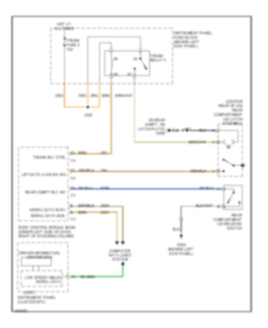
Forced Entry Wiring Diagram for Pontiac G8 GT 2009
List of elements for Forced Entry Wiring Diagram for Pontiac G8 GT 2009:
- (behind left kick panel) g305
- (in body harness) j306
- (in body harness) j317
- (in body harness) j320
- 87a
- Ajar sw sig
- Body control module (bcm) (under left side of dash, right of steering column)
- Computer data lines system
- Door lock/ window switch
- Dr lck ctrl
- Dr unlk
- Dr unlk cntrl
- Dr/lck fuse 3 25a
- Dr/lck relay 2
- Driver door latch assembly (rear of driver front door)
- Drv dr ajar sw sig
- Drv dr lk sw
- Drv dr lk sw lk sig
- Drvr dr/unlck relay 6
- Exterior lights system
- Front passenger door latch assembly (rear of passenger front door)
- Fuel door release actuator
- Fuse suply volt
- G202 (behind left kick panel)
- G304 (behind right kick panel)
- G305 (behind left kick panel)
- G407 (under center of rear parcel shelf)
- Ground
- Hood ajar switch
- Horn relay ctl
- Horns system
- Hot at all times
- Inst/disp/ rfa/dlc fuse 5 10a
- Instrument panel fuse block (behind left kick panel)
- J231
- J339
- J404
- Left rear door latch assembly (rear of left rear door)
- Liftgate
- Pass dr/unlck relay 3
- Pass frt dr
- Pk lamp rly ctl
- Pnk
- Pwr dr lck
- Pwr dr unlk
- Rear compartment lid latch assembly (center rear of lid)
- Rear fuse block (left side of rear compt)
- Remote control door lock receiver (rcdlr)
- Right rear door latch assembly (rear of right rear door)
- Serial data
- Suply volt
- Underhood fuse block (mounted to right front strut tower)
- Unlk sig
- X4 hood ajar sw
- X5 hood clsd sw
- X6 ajar sig
- X7 fuse suply volt
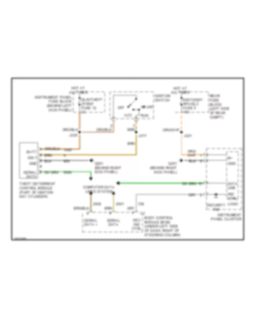
Pass-Key Wiring Diagram for Pontiac G8 GT 2009
List of elements for Pass-Key Wiring Diagram for Pontiac G8 GT 2009:
- Acc
- Batt ign 1 gnd
- Body control module (bcm) (under left side of dash, right of steering column)
- Computer data lines system
- Data line
- Dlis/theft dtrnt fuse 12 2a
- G201 (behind right kick panel)
- Gnd
- Hot at all times
- Ignition switch
- Ind ctrl
- Inst/disp/ rfa/dlc fuse 5 10a
- Instrument panel cluster
- Instrument panel fuse block (behind left kick panel)
- J217
- J220
- J221
- Logic
- Off
- Rear fuse block (left side of rear compt)
- Run
- Sec ind ctrl
- Security ind
- Serial data
- Serial data +
- Start
- Theft deterrent control module (part of ignition key cylinder)
BODY CONTROL MODULES
Body Control Modules Wiring Diagram (1 of 2) for Pontiac G8 GT 2009
List of elements for Body Control Modules Wiring Diagram (1 of 2) for Pontiac G8 GT 2009:
- (behind right kick panel) g201
- 5-volt ref
- A/t shift lk ctrl sol volt
- Acc run
- Anti-lock brakes system
- Anti-theft system
- Batt pos volt
- Body control module (bcm) (under left side of dash, right of steering column)
- Comm enable rly ctrl
- Computer data lines system
- Courtesy lamps sply volt
- Courtesy lamps sw sig
- Cruise control system
- Cruise ctrl sw sig
- Dome lamp sply volt
- Door locks system
- Dr lock ctrl
- Dr unlock ctrl
- Dr unlock sply volt
- Drl ambient light sens sig
- Exterior lights system
- Flash to pass sw sig
- Fog lamp sw
- Gmlan serial data bus+
- Gmlan serial data bus-
- Ground
- Hdlp dimmer sw hi beam sig
- Headlamp dimming sw down
- Headlamp dimming sw up
- Headlamp sw off sig
- Headlamp sw on sig
- Headlights system
- Heated seat sply volt (ka1)
- Hot at all times
- I/p lamp sply volt
- Ign 1 volt
- Ign key resistor lo ref
- Ign key resistor sig
- Ignition switch
- Inadvertent pwr sply volt
- Interior lamp sw sig
- Interior lights system
- J215
- J217
- Key in
- Led backlight dimming ctrl
- Lh turn sig sw
- Lo ref
- Lo speed gmlan serial data
- Off
- Park lamp sw on sig
- Pnk
- Pwr dr lock sply volt
- Pwr dr unlock sply volt
- Rear compt rly sw
- Remote radio ctrl sply volt
- Rh turn sig sw
- Run/crank volt
- Seats system
- Security indicator ctrl
- Shift interlock system
- Start
- Stop lamp sw sig
- Traction ctrl sw sig
- Trans electronic range sig
- Transmissions system
- Trunk, tailgate, fuel doors system
- Windshield washer sw sig
- Windshield wiper sw hi sig
- Windshield wiper sw lo sig
- Wiper sw lo ref
- Wiper/washer system
Body Control Modules Wiring Diagram (2 of 2) for Pontiac G8 GT 2009
List of elements for Body Control Modules Wiring Diagram (2 of 2) for Pontiac G8 GT 2009:
- (in rear compt, on latch plate) g409
- (under left side of dash, right of steering column) body control module (bcm)
- 5-volt ref
- Acc pwr rly ctrl
- Acc wakeup serial data
- Anti-lock brakes system
- Anti-theft system
- Backup lamp rly ctrl
- Batt current sig
- Batt pos vol
- Bcm fuse 9 10a
- Computer data lines system
- Ctsy/trn sig rt fuse 5 15a
- Door locks system
- Driver dr ajar sw sig
- Driver dr lock sw lock sig
- Driver dr lock sw unlock sig
- Exterior lights system
- Fh windshield wiper sw hi sig
- Fog lamp rly ctrl
- Ground
- Headlamp hi beam rly ctrl
- Headlamp lo beam rly ctrl
- Headlamp sply vol
- Headlights system
- Hood ajar sw sig
- Hood closed sw sig
- Horn rly ctrl
- Horns system
- Hot at all times
- Inadv/ pwr/led fuse 4 15a
- Instrument panel fuse block (behind left kick panel)
- Int lamps fuse 11 15a
- J412
- Lf turn sig lamp sply
- Liftgate ajar sw sig
- Low ref
- Lr turn sig lamp sply vol
- Park brake sw sig
- Park lamp rly ctrl
- Pass frt dr ajar sw sig
- Pnk
- Power distribution system
- Rap rly coil sply vol
- Rear fuse block (left side of rear compt)
- Rh frt turn sig lamp sply vol
- Rr turn sig lamp sply vol
- Run/crank ctrl
- Rvc snsr fuse 11 7.5a
- Starting/charging system
- Stop fuse 10 15a
- Stop lamp sply vol
- Stop lamp sw sig
- Trn/ sig lt fuse 8 15a
- Trn/ sig rt fuse 6 15a
- Trunk release rly ctrl
- Trunk, tailgate, fuel doors system
- Washer fluid pump rly ctrl
- Windshield wiper mtr prk sw sig
- Windshield wiper sw sig 2
- Wiper/washer system
COMPUTER DATA LINES
Computer Data Lines Wiring Diagram for Pontiac G8 GT 2009
List of elements for Computer Data Lines Wiring Diagram for Pontiac G8 GT 2009:
- (in front body harness) j111
- (in instrument panel harness) j213
- (left rear of engine compt) g102
- 3.6l
- 5 speed a/t
- 6 speed a/t
- 6.0l/6.2l
- Acc run
- Acc serial data
- Acc wakeup ser data
- Automatic transmission (right rear of transmission)
- Body control module (bcm) (under left side of dash, right of steering column)
- Comm enable fuse 1 10a
- Comm enable relay 2
- Comm enable rly
- Comm enable rly ctrl
- Data link connector (dlc) (under left end of dash)
- Data link resistor
- Digital radio receiver
- Driver information center (dic) display
- Electronic brake control module (ebcm) (right rear of engine compt)
- Engine control module (ecm) (right side of engine compt)
- G201 (behind right kick panel)
- Hi spd serial data +
- Hi spd serial data -
- Hot at all times
- Hvac control module (right side of hvac unit)
- Ignition 1 voltage
- Ignition switch
- Inflatable restraint front passenger presence system (pps) module
- Inflatable restraint sensing & diagnostic module (sdm) (under center console)
- Inst/disp rfa/dlc fuse 5 10a
- Instrument panel cluster (ipc)
- J109 (in front body harness)
- J127
- J217
- J221
- J420 (in body harness)
- Jx200 (in i/p harness, behind instrument panel)
- Lo spd serial data
- Off
- Radio
- Rear fuse block (left side of rear compt)
- Remote control door lock receiver (rcdlr)
- Start
- Steering angle sensor (in steering column)
- Theft deterrent control module (tdm) (part of ignition key cylinder)
- Transmission control module (tcm) (right rear of engine compt)
- Underhood fuse block (mounted to right front strut tower)
- Vehicle communication interface module (vcim)
- Yaw rate & lateral accelerometer sensor (under center console)
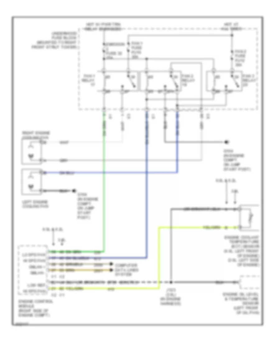
COOLING FAN
Cooling Fan Wiring Diagram for Pontiac G8 GT 2009
List of elements for Cooling Fan Wiring Diagram for Pontiac G8 GT 2009:
- (or 2761)
- 3.6l
- 6.0l & 6.2l
- 87a
- Computer data lines system
- Emission fuse 32 15a
- Engine control module (right side of engine compt)
- Engine coolant temperature (ect) sensor (6.0l: left front of engine) (3.6l: left side of engine)
- Engine oil level & temperature sensor (left front of oil pan)
- Fan 1 fuse fu10 30a
- Fan 1 relay
- Fan 2 fuse fu12 30a
- Fan 2 relay
- Fan 3 relay
- G104 (in engine compt, on jump start post)
- Gmlan +
- Gmlan -
- Hi spd fan
- Hot at all times
- Hot w/ pwr trn relay energized
- J123 (3.6l) (in engine harness)
- Left engine cooling fan
- Lo spd fan
- Low ref
- Right engine cooling fan
- Underhood fuse block (mounted to right front strut tower)
CRUISE CONTROL
Cruise Control Wiring Diagram for Pontiac G8 GT 2009
List of elements for Cruise Control Wiring Diagram for Pontiac G8 GT 2009:
- 3.6l
- 5 volt ref
- 6.0l & 6.2l
- Accelerator pedal position (app) sensor (under left side of dash)
- App sens 1 sig
- App sens 2 sig
- Automatic transmission (6 speed a/t) (right rear of transmission)
- Automatic transmission (right rear of transmission)
- Automatic transmission shift lever
- Batt
- Batt pos volt
- Bcm fuse 9 10a
- Body control module (bcm) (under left side of dash, right of steering column)
- Brake pedal position (bpp) sensor (top of brake pedal assembly)
- Computer data lines system
- Control solenoid valve assembly
- Cruise ctrl sw sig
- Cruise ind
- Data bus +
- Data bus -
- Driver information center (dic)
- Ecm batt fuse 10 15a
- Engine control module (ecm) (right side of engine compt)
- Hot at all times
- Input shaft speed (iss) sensor
- Inst/disp/ rfa/dlc fuse 5 10a
- Instrument panel cluster (ipc)
- Instrument panel fuse block (behind left kick panel)
- J143 (in automatic transmission harness)
- J218 (in instrument panel harness)
- J221
- Lo spd ser data
- Logic
- Low ref
- On/off
- Output shaft speed (oss) sensor
- Rear fuse block (left side of rear compt)
- Red
- Red b
- Res +
- Set -
- Sply volt
- Stop lp sw sig
- Tac mtr ctrl 1
- Tac mtr ctrl 2
- Throttle body (center front of engine)
- Tp sens 1 sig
- Tp sens 2 sig
- Transmission control module (tcm)
- Transmission control module (tcm) (5 speed a/t) (right rear of engine compt)
- Turn/signal multi- function switch
- Vss high sig
- Vss low sig
DEFOGGERS
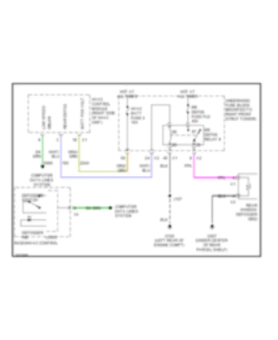
Defoggers Wiring Diagram for Pontiac G8 GT 2009
List of elements for Defoggers Wiring Diagram for Pontiac G8 GT 2009:
- Batt pos volt
- Computer data lines system
- Defogger ind
- Defogger switch
- G102 (left rear of engine compt)
- G407 (under center of rear parcel shelf)
- Gmlan
- Hot at all times
- Hvac batt fuse 2 10a
- Hvac control module (right side of hvac unit)
- J127
- Logic
- Low speed
- Radio/hvac control
- Rear defog
- Rear window defogger grid
- Rr defog fuse fu2 40a
- Rr defog relay 8
- Underhood fuse block (mounted to right front strut tower)
ENGINE PERFORMANCE
3.6L VIN 7
3.6L VIN 7, Engine Performance Wiring Diagram (1 of 5) for Pontiac G8 GT 2009
List of elements for 3.6L VIN 7, Engine Performance Wiring Diagram (1 of 5) for Pontiac G8 GT 2009:
- (in engine harness) j123
- 5v ref
- Cam phaser exhaust 1 sig
- Cam phaser exhaust 2 sig
- Cam phaser intake 1 sig
- Cam phaser intake 2 sig
- Camshaft position (cmp) exhaust sensor 1 (front of right cylinder bank)
- Camshaft position (cmp) exhaust sensor 2 (front of left cylinder bank)
- Camshaft position (cmp) intake sensor 1 (front of right cylinder bank)
- Camshaft position (cmp) intake sensor 2 (front of left cylinder bank)
- Ckp sens 1 sig
- Crankshaft position (ckp) sensor (lower right rear of engine)
- Engine control module (ecm) (right side of engine compt)
- Engine coolant temperature (ect) sensor (left side of engine)
- Engine oil level/ temperature sensor (left front of oil pan)
- Engine oil pressure (eop) sensor (top left front of engine)
- Evap cnstr purge sol ctrl
- Exhaust 1 cam pos sens sig
- Exhaust 2 cam pos sens sig
- Fuel inj 1 ctrl
- Fuel inj 2 ctrl
- Fuel inj 3 ctrl
- Fuel inj 4 ctrl
- Fuel inj 5 ctrl
- Fuel inj 6 ctrl
- Generator field duty cycle sig
- Generator turn on sig
- Ic 1 ctrl
- Ic 3 ctrl
- Ic 5 ctrl
- Imt sol vlv
- Intake 1 cam pos sens sig
- Intake 2 cam pos sens sig
- J116 (in engine harness)
- J117 (in engine harness)
- Knock sens 1 sig
- Knock sensor (ks) 1 (right side of engine block)
- Knock sensor (ks) 2 (top left rear of engine)
- Low ref
- Oil lvl sw sig
- Pnk
- Sens sig
- Starting/charging system
- Tac mtr ctrl 1
- Tac mtr ctrl 2
3.6L VIN 7, Engine Performance Wiring Diagram (2 of 5) for Pontiac G8 GT 2009
List of elements for 3.6L VIN 7, Engine Performance Wiring Diagram (2 of 5) for Pontiac G8 GT 2009:
- (in engine harness) j115
- (in engine harness) j121
- Camshaft position (cmp) exhaust solenoid 1 (front of right cylinder bank)
- Camshaft position (cmp) exhaust solenoid 2 (front of left cylinder bank)
- Camshaft position (cmp) intake solenoid 1 (front of right cylinder bank)
- Camshaft position (cmp) intake solenoid 2 (front of left cylinder bank)
- Computer data lines system
- Driver information center (dic)
- Evaporative emission (evap) canister purge solenoid valve (top left rear of engine)
- Heated oxygen sensor (ho2s) bank 1 sensor 1 (on right bank exhaust manifold)
- Heated oxygen sensor (ho2s) bank 2 sensor 1 (on left bank exhaust manifold)
- Ign
- Instrument panel cluster (ipc)
- Intake manifold tuning (imt) solenoid valve
- Lo spd gmlan serial data
- Logic
- Low oil pressure ind
- Malfunction ind
- Pnk
3.6L VIN 7, Engine Performance Wiring Diagram (3 of 5) for Pontiac G8 GT 2009
List of elements for 3.6L VIN 7, Engine Performance Wiring Diagram (3 of 5) for Pontiac G8 GT 2009:
- (behind left kick panel) instrument panel fuse block
- Above respective cylinders) fuel injectors
- Ecm batt fuse 10 15a
- Ect sens sig
- Engine control module(ecm) (right side of engine compt)
- Fuel pump fuse 12 20a
- Fuel pump relay
- G202 (behind left kick panel)
- Ho2s high sig
- Ho2s htr lo ctrl
- Ho2s low sig
- Hot at all times
- Ic 2 ctrl
- Ic 4 ctrl
- Ic 6 ctrl
- Inst/disp/ rfa/dlc fuse 5 10a
- Knock sens 2 sig
- Low ref
- Oil press sens sig
- Oil temp sens sig
- Pnk
- Rear fuse block (left side of rear compt)
- Tan
- Throttle body (center front of engine)
- Tp sens 1 sig
- Tp sens 2 sig
3.6L VIN 7, Engine Performance Wiring Diagram (4 of 5) for Pontiac G8 GT 2009
List of elements for 3.6L VIN 7, Engine Performance Wiring Diagram (4 of 5) for Pontiac G8 GT 2009:
- (in fuel injector harness) j135
- (in right headlamp harness) j137
- Canister vent fuse 22 10a
- Ecm 1 fuse 15a
- Emission 1 fuse 15a
- Emission 2 fuse 32 15a
- Eng ign fuse 10a
- Evn coils fuse 20a
- Fan 1 relay
- Fan 2 relay
- Fan 3 relay
- G108 (right rear of engine block)
- G109 (left middle of engine block)
- Hot at all times
- Hot w/ ign relay 14 energized
- Ignition coil 1 (top of right cylinder bank)
- Ignition coil 2 (top of left cylinder bank)
- Ignition coil 3 (top of right cylinder bank)
- Ignition coil 4 (top of left cylinder bank)
- Ignition coil 5 (top of right cylinder bank)
- Ignition coil 6 (top of left cylinder bank)
- J105
- J106
- J114 (in engine harness) pnk
- J118 (in engine harness)
- J120
- J139 (in front object alarm harness)
- J146
- Nca
- Odd coils fuse 20a
- Plug spark
- Pnk
- Pnk b
- Pnk d
- Pwr trn relay 13
- Spark plug
- Underhood fuse block (mounted to right front strut tower)
3.6L VIN 7, Engine Performance Wiring Diagram (5 of 5) for Pontiac G8 GT 2009
List of elements for 3.6L VIN 7, Engine Performance Wiring Diagram (5 of 5) for Pontiac G8 GT 2009:
- (downstream of right catalytic converter) heated oxygen sensor (ho2s) bank 1 sensor 2
- (in exhaust system, rear of left catalytic converter) heated oxygen sensor (ho2s) bank 2 sensor 2
- 5v ref
- A/c refrig press sens
- Acc wakeup serial data
- Accelerator pedal position (app) sensor (under left side of dash)
- Air conditioning system
- App sens 1 sig
- App sens 2 sig
- App sensor 1
- App sensor 2
- Batt positive volt
- Computer data lines system
- Cooling fans system
- Engine control module (ecm) (right side of engine compt)
- Evaporative emission (evap) canister vent solenoid valve
- Exterior lights system
- Fuel level sensor
- Fuel level sensor (secondary) (in fuel tank)
- Fuel lvl sens sig 1
- Fuel lvl sens sig 2
- Fuel press sig
- Fuel pump
- Fuel pump &
- Fuel pump rly ctrl
- Fuel sys cnstr vent
- Fuel tank
- G106 (right front of engine block)
- G304 (behind right kick panel)
- Gmlan serial data bus+
- Gmlan serial data bus-
- Gnd
- Hi spd cooling fan rly
- Ho2s high sig
- Ho2s htr lo ctrl
- Ho2s low sig
- Iat sens sig
- Ign 1 volt
- J122
- J124 (in engine harness)
- J330 (in fuel tank harness)
- Lo spd cooling fan rly
- Low ref
- Maf sens sig
- Main rly ctrl
- Mass air flow (maf)/intake air temperature (iat) sensor (front of engine, in air cleaner duct)
- Mil ctrl
- Park/neutral sig
- Pnk
- Pressure (ftp) sensor
- Sender assembly (in fuel tank)
- Sens sig
- Starter rly coil ctrl
- Starting/charging system
- Stop lamp sw sig
6.0L VIN Y
6.0L VIN Y, Engine Performance Wiring Diagram (1 of 5) for Pontiac G8 GT 2009
List of elements for 6.0L VIN Y, Engine Performance Wiring Diagram (1 of 5) for Pontiac G8 GT 2009:
- (right front of engine block) g106
- 5v ref
- 5v rtn brk booster vacuum
- A/c refrig press sens sig
- Acc wakeup serial data
- Accelerator pedal position (app) sensor (under left side of dash)
- Air conditioning system
- Anti-lock brakes system
- App sens 1 sig
- App sens 2 sig
- App sensor 1
- App sensor 2
- Backup lamp switch (m/t)
- Backup sw sig
- Batt positive volt
- Brk booster vacuum sens
- Clutch pedal position (cpp) sensor (m/t) (under left side of dash)
- Computer data lines system
- Cooling fans system
- Cpp sens sig
- Ecm batt fuse 10 15a
- Engine control module (ecm) (right side of engine compt)
- Exterior lights system
- Fuel lvl sens sig
- Fuel pump fuse 12 20a
- Fuel pump relay
- Fuel pump rly ctrl
- Fuel tank pressure (ftp) sensor
- Fuel tank vapour press
- G202 (behind left kick panel)
- Gmlan serial data bus+
- Gmlan serial data bus-
- Heated oxygen sensor (ho2s) bank 1 sensor 2 (downstream of right catalytic converter)
- Hi spd cooling fan rly ctrl
- Ho2s high sig
- Ho2s low sig
- Hot at all times
- Iat sens sig
- Ign 1 volt
- Inst/disp/ rfa/dlc fuse 5 10a
- Instrument panel fuse block (behind left kick panel)
- J122
- J221
- Lo spd cooling fan rly ctrl
- Low ref
- Maf sens sig
- Main rly ctrl
- Park/neutral sig
- Pnk
- Rear fuse block (left side of rear compt)
- Starter rly coil ctrl
- Starting/charging system
- Stop lamp sw sig
6.0L VIN Y, Engine Performance Wiring Diagram (2 of 5) for Pontiac G8 GT 2009
List of elements for 6.0L VIN Y, Engine Performance Wiring Diagram (2 of 5) for Pontiac G8 GT 2009:
- (in fuel tank harness)
- Computer data lines system
- Driver information center (dic)
- Eng ign fuse 39 10a
- Engine control module (ecm) (right side of engine compt)
- Evaporative emission (evap) canister vent solenoid valve
- Fuel level sensor
- Fuel level sensor (secondary) (in fuel tank)
- Fuel lvl sens sig
- Fuel pump
- Fuel pump &
- Fuel tank vent
- G110 (right front of engine block)
- G304 (behind right kick panel)
- Gnd
- Heated oxygen sensor (ho2s) bank 2 sensor 2 (downstream of left catalytic converter)
- Ho2s high sig
- Ho2s htr low
- Hot w/ ign relay energized
- Ign
- Ign 1 volt
- Instrument panel cluster (ipc)
- J120
- J330
- Lo spd gmlan serial data
- Logic
- Low oil pressure ind
- Malfunction ind
- Mass air flow (maf)/intake air temperature (iat) sensor (left front of engine compt, in air cleaner duct)
- Mil ctrl
- Oss high sig
- Oss low sig
- Output speed sensor (oss) (m/t)
- Pnk
- Sender assembly (in fuel tank)
- Sens sig
- Skip shift solenoid
- Skip shift solenoid (m/t)
- Underhood fuse block (mounted to right front strut tower)
6.0L VIN Y, Engine Performance Wiring Diagram (3 of 5) for Pontiac G8 GT 2009
List of elements for 6.0L VIN Y, Engine Performance Wiring Diagram (3 of 5) for Pontiac G8 GT 2009:
- (in engine harness) j114
- (in engine harness) j121
- (in even ignition coil harness) j132
- Canister vent fuse 22 10a
- Ecm 1 fuse 15a
- Emission 1 fuse 15a
- Emission 2 fuse 32 15a
- Eng ign fuse 10a
- Evn coils fuse 20a
- Fan 1 relay
- Fan 2 relay
- Fan 3 relay
- G110 (right front of engine block)
- Hot at all times
- Hot w/ ign relay 14 energized
- Ignition coil 2 (top left side of engine)
- Ignition coil 4 (top left side of engine)
- Ignition coil 6 (top left side of engine)
- Ignition coil 8 (top left side of engine)
- J120
- J141 (in even ignition coil harness)
- Knock sensor (ks) (right side of engine block)
- Knock sensor (ks) (top left rear of engine)
- Nca
- Odd coils fuse 20a
- Plug spark
- Pnk
- Pwr trn relay 13
- Spark plug
- Underhood fuse block (mounted to right front strut tower)
6.0L VIN Y, Engine Performance Wiring Diagram (4 of 5) for Pontiac G8 GT 2009
List of elements for 6.0L VIN Y, Engine Performance Wiring Diagram (4 of 5) for Pontiac G8 GT 2009:
- (front of engine, above crankshaft pulley) camshaft position (cmp) sensor
- (in engine harness) j118
- (in odd ignition coil harness) j133
- (top of left cylinder bank) fuel injectors
- (top of right cylinder bank) fuel injectors
- 5v ref
- Ckp sens sig
- Cmp sens sig
- Crankshaft position (ckp) sensor (lower right rear of engine)
- Engine control module (ecm) (right side of engine compt)
- G112 (left rear of engine block)
- Gen turn on sig
- Ic 1 ctrl
- Ic 2 ctrl
- Ic 3 ctrl
- Ic 4 ctrl
- Ic 5 ctrl
- Ic 6 ctrl
- Ic 7 ctrl
- Ic 8 ctrl
- Ignition coil 1 (top right side of engine)
- Ignition coil 3 (top right side of engine)
- Ignition coil 5 (top right side of engine)
- Ignition coil 7 (top right side of engine)
- J130
- J142 (in odd ignition coil harness)
- Low ref
- Nca
- Plug spark
- Pnk
- Sens sig
- Spark plug
- Starting/ charging system
- Tp sens 2 sig
6.0L VIN Y, Engine Performance Wiring Diagram (5 of 5) for Pontiac G8 GT 2009
List of elements for 6.0L VIN Y, Engine Performance Wiring Diagram (5 of 5) for Pontiac G8 GT 2009:
- (left front of engine) engine coolant temperature (ect) sensor
- (m/t)
- (or reverse sol)
- (top front of engine) evaporative emission (evap) canister purge solenoid valve
- 5v ref
- Cyl shut off sol 1
- Cyl shut off sol 2
- Cyl shut off sol 3
- Cyl shut off sol 4
- Ect sens sig
- Emission (evap) canister purge solenoid valve
- Engine control module (ecm) (right side of engine compt)
- Engine oil level/ temperature sensor (right side of oil pan)
- Engine oil pressure (eop) sensor (top rear of engine)
- Evap cnstr purge sol ctrl
- Fuel inj 1 ctrl
- Fuel inj 2 ctrl
- Fuel inj 3 ctrl
- Fuel inj 4 ctrl
- Fuel inj 5 ctrl
- Fuel inj 6 ctrl
- Fuel inj 7 ctrl
- Fuel inj 8 ctrl
- Gen field duty cycle sig
- Heated oxygen sensor (ho2s) bank 1 sensor 1 (in right bank exhaust manifold)
- Heated oxygen sensor (ho2s) bank 2 sensor 1 (in left bank exhaust manifold)
- Ho2s high sig
- Ho2s htr low
- Ho2s low sig
- Hot w/ ign relay energized
- Knock sens 1 sig
- Knock sens 2 sig
- Knock sens sig rtn
- Low ref
- Manifold absolute pressure (map) sensor (top front of engine)
- Map sens sig
- Oil lvl sw sig
- Oil press sens sig
- Oil temp sens sig
- Rev/lock fuse 25 15a
- Starting/charging system
- Tac mtr ctrl 1
- Tac mtr ctrl 2
- Throttle body (center front of engine)
- Underhood fuse block (mounted to right front strut tower)
- Valve lifter oil manifold (vlom) assembly
6.2L VIN W
6.2L VIN W, Engine Performance Wiring Diagram (1 of 5) for Pontiac G8 GT 2009
List of elements for 6.2L VIN W, Engine Performance Wiring Diagram (1 of 5) for Pontiac G8 GT 2009:
- (right front of engine block) g106
- 5v ref
- 5v rtn brk booster vacuum
- A/c refrig press sens sig
- Acc wakeup serial data
- Accelerator pedal position (app) sensor (under left side of dash)
- Air conditioning system
- Anti-lock brakes system
- App sens 1 sig
- App sens 2 sig
- App sensor 1
- App sensor 2
- Backup lamp switch (m/t)
- Backup sw sig
- Batt positive volt
- Brk booster vacuum sens
- Clutch pedal position (cpp) sensor (m/t) (under left side of dash)
- Computer data lines system
- Cooling fans system
- Cpp sens sig
- Ecm batt fuse 10 15a
- Engine control module (ecm) (right side of engine compt)
- Exterior lights system
- Fuel lvl sens sig
- Fuel pump fuse 12 20a
- Fuel pump relay
- Fuel pump rly ctrl
- Fuel tank pressure (ftp) sensor
- Fuel tank vapour press
- G202 (behind left kick panel)
- Gmlan serial data bus+
- Gmlan serial data bus-
- Heated oxygen sensor (ho2s) bank 1 sensor 2 (downstream of right catalytic converter)
- Hi spd cooling fan rly ctrl
- Ho2s high sig
- Ho2s low sig
- Hot at all times
- Iat sens sig
- Ign 1 volt
- Inst/disp/ rfa/dlc fuse 5 10a
- Instrument panel fuse block (behind left kick panel)
- J122
- J221
- Lo spd cooling fan rly ctrl
- Low ref
- Maf sens sig
- Main rly ctrl
- Park/neutral sig
- Pnk
- Rear fuse block (left side of rear compt)
- Starter rly coil ctrl
- Starting/charging system
- Stop lamp sw sig
6.2L VIN W, Engine Performance Wiring Diagram (2 of 5) for Pontiac G8 GT 2009
List of elements for 6.2L VIN W, Engine Performance Wiring Diagram (2 of 5) for Pontiac G8 GT 2009:
- (in fuel tank harness)
- Computer data lines system
- Driver information center (dic)
- Eng ign fuse 39 10a
- Engine control module (ecm) (right side of engine compt)
- Evaporative emission (evap) canister vent solenoid valve
- Fuel level sensor
- Fuel level sensor (secondary) (in fuel tank)
- Fuel lvl sens sig
- Fuel pump
- Fuel pump &
- Fuel tank vent
- G110 (right front of engine block)
- G304 (behind right kick panel)
- Gnd
- Heated oxygen sensor (ho2s) bank 2 sensor 2 (downstream of left catalytic converter)
- Ho2s high sig
- Ho2s htr low
- Hot w/ ign relay energized
- Ign
- Ign 1 volt
- Instrument panel cluster (ipc)
- J120
- J330
- Lo spd gmlan serial data
- Logic
- Low oil pressure ind
- Malfunction ind
- Mass air flow (maf)/intake air temperature (iat) sensor (left front of engine compt, in air cleaner duct)
- Mil ctrl
- Oss high sig
- Oss low sig
- Output speed sensor (oss) (m/t)
- Pnk
- Sender assembly (in fuel tank)
- Sens sig
- Skip shift solenoid
- Skip shift solenoid (m/t)
- Underhood fuse block (mounted to right front strut tower)
6.2L VIN W, Engine Performance Wiring Diagram (3 of 5) for Pontiac G8 GT 2009
List of elements for 6.2L VIN W, Engine Performance Wiring Diagram (3 of 5) for Pontiac G8 GT 2009:
- (in engine harness) j114
- (in engine harness) j121
- (in even ignition coil harness) j132
- Canister vent fuse 22 10a
- Ecm 1 fuse 15a
- Emission 1 fuse 15a
- Emission 2 fuse 32 15a
- Eng ign fuse 10a
- Evn coils fuse 20a
- Fan 1 relay
- Fan 2 relay
- Fan 3 relay
- G110 (right front of engine block)
- Hot at all times
- Hot w/ ign relay 14 energized
- Ignition coil 2 (top left side of engine)
- Ignition coil 4 (top left side of engine)
- Ignition coil 6 (top left side of engine)
- Ignition coil 8 (top left side of engine)
- J120
- J141 (in even ignition coil harness)
- Knock sensor (ks) (right side of engine block)
- Knock sensor (ks) (top left rear of engine)
- Nca
- Odd coils fuse 20a
- Plug spark
- Pnk
- Pwr trn relay 13
- Spark plug
- Underhood fuse block (mounted to right front strut tower)
6.2L VIN W, Engine Performance Wiring Diagram (4 of 5) for Pontiac G8 GT 2009
List of elements for 6.2L VIN W, Engine Performance Wiring Diagram (4 of 5) for Pontiac G8 GT 2009:
- (front of engine, above crankshaft pulley) camshaft position (cmp) sensor
- (in engine harness) j118
- (in odd ignition coil harness) j133
- (top of left cylinder bank) fuel injectors
- (top of right cylinder bank) fuel injectors
- 5v ref
- Ckp sens sig
- Cmp sens sig
- Crankshaft position (ckp) sensor (lower right rear of engine)
- Engine control module (ecm) (right side of engine compt)
- G112 (left rear of engine block)
- Gen turn on sig
- Ic 1 ctrl
- Ic 2 ctrl
- Ic 3 ctrl
- Ic 4 ctrl
- Ic 5 ctrl
- Ic 6 ctrl
- Ic 7 ctrl
- Ic 8 ctrl
- Ignition coil 1 (top right side of engine)
- Ignition coil 3 (top right side of engine)
- Ignition coil 5 (top right side of engine)
- Ignition coil 7 (top right side of engine)
- J130
- J142 (in odd ignition coil harness)
- Low ref
- Nca
- Plug spark
- Pnk
- Sens sig
- Spark plug
- Starting/ charging system
- Tp sens 2 sig
6.2L VIN W, Engine Performance Wiring Diagram (5 of 5) for Pontiac G8 GT 2009
List of elements for 6.2L VIN W, Engine Performance Wiring Diagram (5 of 5) for Pontiac G8 GT 2009:
- (left front of engine) engine coolant temperature (ect) sensor
- (m/t)
- (or reverse sol)
- (top front of engine) evaporative emission (evap) canister purge solenoid valve
- 5v ref
- Cyl shut off sol 1
- Cyl shut off sol 2
- Cyl shut off sol 3
- Cyl shut off sol 4
- Ect sens sig
- Emission (evap) canister purge solenoid valve
- Engine control module (ecm) (right side of engine compt)
- Engine oil level/ temperature sensor (right side of oil pan)
- Engine oil pressure (eop) sensor (top rear of engine)
- Evap cnstr purge sol ctrl
- Fuel inj 1 ctrl
- Fuel inj 2 ctrl
- Fuel inj 3 ctrl
- Fuel inj 4 ctrl
- Fuel inj 5 ctrl
- Fuel inj 6 ctrl
- Fuel inj 7 ctrl
- Fuel inj 8 ctrl
- Gen field duty cycle sig
- Heated oxygen sensor (ho2s) bank 1 sensor 1 (in right bank exhaust manifold)
- Heated oxygen sensor (ho2s) bank 2 sensor 1 (in left bank exhaust manifold)
- Ho2s high sig
- Ho2s htr low
- Ho2s low sig
- Hot w/ ign relay energized
- Knock sens 1 sig
- Knock sens 2 sig
- Knock sens sig rtn
- Low ref
- Manifold absolute pressure (map) sensor (top front of engine)
- Map sens sig
- Oil lvl sw sig
- Oil press sens sig
- Oil temp sens sig
- Rev/lock fuse 25 15a
- Starting/charging system
- Tac mtr ctrl 1
- Tac mtr ctrl 2
- Throttle body (center front of engine)
- Underhood fuse block (mounted to right front strut tower)
- Valve lifter oil manifold (vlom) assembly
EXTERIOR LIGHTS
Backup Lamps Wiring Diagram for Pontiac G8 GT 2009
List of elements for Backup Lamps Wiring Diagram for Pontiac G8 GT 2009:
- (in body harness) j238
- (under left side of dash, right of steering column) body control module (bcm)
- Automatic transmission (5 speed a/t) (right rear of transmission)
- Automatic transmission (6 speed a/t) (right rear of transmission)
- Automatic transmission internal mode switch (ims)
- Automatic transmission shift lever
- Backup lp fuse 3 15a
- Backup lp relay 4
- Computer data lines system
- Control solenoid valve assembly
- Cruise control system
- G106 (right front of engine block)
- G409 (in rear compt, on latch plate)
- Gnd
- Hot at all times
- Inside rearview mirror (isrvm)
- J122
- J218 (in instrument panel harness)
- J406 (in rear body harness)
- J414
- J415
- Left backup lamp
- Red
- Right backup lamp
- Serial data bus+
- Serial data bus-
- Sig a
- Sig b
- Sig c
- Switch sig a
- Switch sig b
- Switch sig c
- Transmission control module (tcm)
- Transmission control module (tcm) (right rear of engine compt)
- Underhood fuse block (mounted to right front strut tower)
- X175
Exterior Lamps Wiring Diagram (1 of 2) for Pontiac G8 GT 2009
List of elements for Exterior Lamps Wiring Diagram (1 of 2) for Pontiac G8 GT 2009:
- (behind right kick panel) g201
- 5-volt
- Auto
- Batt +ve volt
- Body control module (bcm) (under left side of dash, right of steering column)
- Brake pedal position (bpp) sensor (top of brake pedal assembly)
- Center high mounted stop lamp (chmsl)
- Computer data lines system
- G104 (in engine compt, on jump start post)
- G201 (behind right kick panel)
- G304 (behind right kick panel)
- G305 (behind left kick panel)
- G409 (in rear compt, on latch plate)
- Head
- Headlamp & panel dimmer switch
- Hot at all times
- Instrument panel cluster (ipc)
- Instrument panel fuse block (behind left kick panel)
- J136
- J137
- J305 (in body harness)
- J321 (in body harness)
- J324
- J414
- J415
- Left
- Left park turn signal lamp
- Left rear turn signal lamp
- Left turn ind
- Left turn signal repeater lamp
- Lf turn sig
- Logic
- Low ref
- Lr turn sig
- Lt turn sig
- Off
- Park
- Prk lamp rly
- Prk lamp sig
- Red
- Rf turn sig
- Right
- Right park turn signal lamp
- Right rear turn signal lamp
- Right turn ind
- Right turn signal repeater lamp
- Rr turn sig
- Rt turn sig
- Serial data
- Stop fuse 10 15a
- Stop lamp sw
- Stop lmp volt
- Trn/sig lt fuse 8 15a
- Trn/sig rt fuse 6 15a
- Turn signal/ multi-function switch
- Underhood fuse block (mounted to right front strut tower)
Exterior Lamps Wiring Diagram (2 of 2) for Pontiac G8 GT 2009
List of elements for Exterior Lamps Wiring Diagram (2 of 2) for Pontiac G8 GT 2009:
- (in front body harness) j104
- (in front body harness) j108
- (in rear body harness) j408
- 3.6l
- 6.0l & 6.2l
- Automatic transmission (except 3.6l) (right rear of transmission)
- Computer data lines system
- Engine control module (ecm) (right side of engine compt)
- G102 (left rear of engine compt)
- G104 (in engine compt, on jump start post)
- G304 (behind right kick panel)
- G409 (in rear compt, on latch plate)
- Grd
- Hazard switch logic
- Hot at all times
- J131
- J136
- J137
- J400 (in body harness)
- J416
- J417
- J418 (in right taillight harness)
- Left front park lamp
- Left front side marker lamp
- Left license lamp
- Left rear side marker lamp
- Left tail/ stop lamp
- Lt prk fuse 10a
- Mjr
- Mnr
- Prk lamp relay 18
- Radio
- Radio/hvac display
- Red
- Right front park lamp
- Right front side marker lamp
- Right license lamp
- Right rear side marker lamp
- Right tail/ stop lamp
- Rt prk fuse 10a
- Transmission control module (tcm) (3.6l) (right rear of engine compt)
- Underhood fuse block (mounted to right front strut tower)
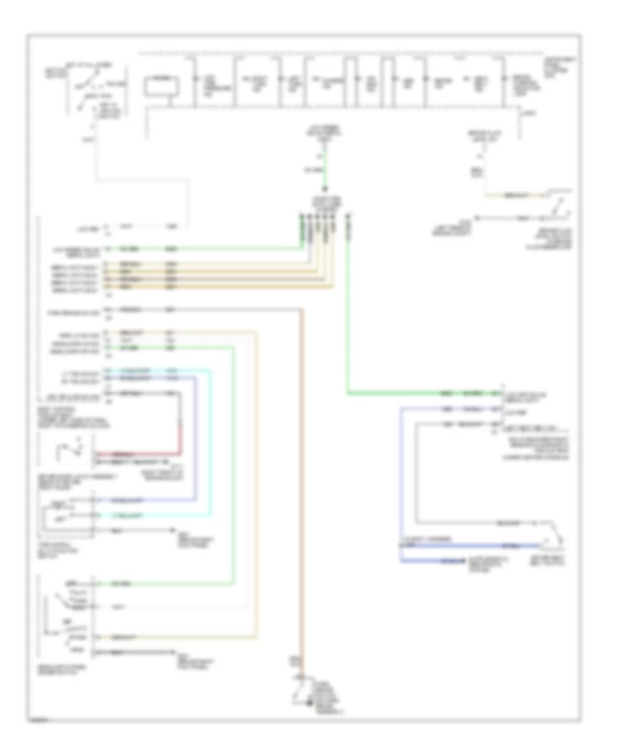
GROUND DISTRIBUTION
Ground Distribution Wiring Diagram (1 of 4) for Pontiac G8 GT 2009
List of elements for Ground Distribution Wiring Diagram (1 of 4) for Pontiac G8 GT 2009:
- (mounted to right front strut tower) underhood fuse block
- (right front of engine block)
- (right side of engine block)
- Ambient light sensor
- Automatic transmission shift lever
- Blower control module
- Body control module (bcm)
- Center console multi-function switch
- Center high mounted stop lamp (chmsl)
- Cigar lighter
- Data link connector (dlc)
- Fan 2 relay 19
- Front dome/ reading lamps
- G103 (in engine compartment, on abs bracket)
- G104 (in engine compartment, on jump start post)
- G111 (6.0l) g107 (3.6l)
- G201 (behind right kick panel)
- G310 (top of steering column)
- Headlamp & dimmer panel switch
- Hood ajar switch
- Hvac control module
- I/p accessory power outlet
- Ignition key cylinder lamp
- Inflatable restraint steering wheel module coil
- Instrument panel cluster (ipc)
- J103 (in forward lamp harness)
- J240 (in steering wheel harness)
- J325 (in headliner harness)
- Left engine cooling fan
- Left front courtesy/ reading lamps
- Left front park lamp
- Left front turn signal lamp
- Left high beam headlamp
- Left horn
- Left sunshade
- Nca
- Rear dome/ reading lamps
- Right front courtesy/ reading lamps
- Right front park lamp
- Right front turn signal lamp
- Right high beam headlamp
- Right horn
- Right sunshade
- Steering wheel control switch
- Sunroof control module
- Sunroof switch
- Theft deterrent module (tdm)
- Turn signal/ multi-function switch
- W/ electric glass sliding sunroof
- W/o electric sun glass sliding
- Windshield washer fluid pump
- X115
- X116
Ground Distribution Wiring Diagram (2 of 4) for Pontiac G8 GT 2009
List of elements for Ground Distribution Wiring Diagram (2 of 4) for Pontiac G8 GT 2009:
- (behind left kick panel) i/p fuse block
- 87a
- Accy relay 8
- Battery
- Dr/lck relay 2
- Driver information center (dic)
- Drvr dr/unlock relay 6
- Fuel pump & sender assembly
- Fuel relay 12
- G202 (behind left kick panel)
- G303 (behind right center of dash)
- G304 (behind right kick panel)
- G308 (under center console)
- G401 (rear compartment, on left rear beam)
- G407 (under center of rear panel shelf)
- Inflatable restraint passenger presence
- Inflatable restraint sensing & diagnostic
- Inside rear view mirror (isrvm)
- J209 (in instrument panel harness)
- J314 (in body harness)
- J322 (in seat harness)
- Left inflatable restraint side impact module
- Left license lamp
- Module (sdm)
- Pass dr/ unlck relay 3
- Passenger back heated seat element
- Passenger heated seat control module
- Passenger seat adjuster switch
- Radio
- Rap 1 relay 1
- Rap 2 relay 7
- Rear compartment lid release switch
- Rear window defogger grid
- Remote control door lock receiver (rcdlr)
- Right front door latch
- Right inflatable restraint side impact module
- Right license lamp
- Right rear door latch
- Right turn signal repeater lamp
- System (pps) module
- Vehicle communication interface module (vcim)
- W/ front seat heater
- Window control module
- X2 a
Ground Distribution Wiring Diagram (3 of 4) for Pontiac G8 GT 2009
List of elements for Ground Distribution Wiring Diagram (3 of 4) for Pontiac G8 GT 2009:
- (6.0l) (right front of engine block)
- (6.0l) (right rear of engine block)
- (w/ preset equalizer, 150w 6 cd changer in head unit audio system) audio amplifier
- Body control module (bcm)
- Center console compartment accessory power outlet
- Cigar lighter console
- Compartment lid latch
- Door lock/ window switch
- Driver back heated seat element
- Driver heated seat control module
- Driver seat adjuster switch
- Engine control module (ecm)
- G110
- G112
- G305 (behind left kick panel)
- G409 (in rear compt on latch plate)
- Ignition coil 1
- Ignition coil 2
- Ignition coil 3
- Ignition coil 4
- Ignition coil 5
- Ignition coil 6
- Ignition coil 7
- Ignition coil 8
- J130 (in ignition coil harness)
- J141 (in even ignition coil harness)
- J323 (in seat harness)
- J407 (in rear body harness)
- J412 (in rear body harness)
- J414 (in right taillight harness)
- J415 (in left taillight harness)
- J416 (in right taillight harness)
- J417 (in left taillight harness)
- Left backup lamp
- Left front door latch
- Left rear door latch
- Left rear side marker lamp
- Left rear turn signal lamp
- Left tail/ stop lamp
- Left turn signal repeater lamp
- Mass air flow (maf)/ intake air temperature (iat) sensor
- Rear
- Right backup lamp
- Right rear side marker lamp
- Right rear turn signal lamp
- Right tail/ stop lamp
- Transmission control module (tcm)
- W/ front seat heater
- X400
- X401
Ground Distribution Wiring Diagram (4 of 4) for Pontiac G8 GT 2009
List of elements for Ground Distribution Wiring Diagram (4 of 4) for Pontiac G8 GT 2009:
- (6 speed a/t) backup lamp switch
- (mounted to right front strut tower) underhood fuse block
- Automatic transmission
- Brake fluid level switch
- Comm enable relay 2
- Crnk relay 12
- Electronic brake control module (ebcm)
- Engine control module (ecm)
- G102 (left rear of engine compt)
- G106 (3.6l) (right front of engine block)
- G108 (3.6l) (right rear of engine block)
- G109 (3.6l) (left middle of engine block)
- Ign relay 14
- Ignition coil 1
- Ignition coil 2
- Ignition coil 3
- Ignition coil 4
- Ignition coil 5
- Ignition coil 6
- Internal mode switch (ims)
- J102 (in forward lamp harness)
- J105 (in engine harness)
- J106 (in engine harness)
- J122 (in engine harness)
- J127 (in engine harness)
- J131 (in front object alarm harness)
- Left front fog lamp
- Left front side
- Left low beam headlamp
- Marker lamp
- Mass air flow (maf)/ intake air temperature (iat) sensor
- Right front fog lamp
- Right front side
- Right low beam headlamp
- Rr defog relay 8
- Theft deterrent alarm siren
- Transmission control module (tcm)
- Windshield wiper motor
- Wpr lo relay 10
- X115
- X116
- X175
- X2 a
HEADLIGHTS
Headlights Wiring Diagram for Pontiac G8 GT 2009
List of elements for Headlights Wiring Diagram for Pontiac G8 GT 2009:
- (behind right kick panel) g201
- (in front object alarm harness) j138
- Air conditioning system
- Amb lt sens sig
- Ambient light sensor (under left top of dash)
- Ambient light/ sunload sensor (under left top of dash)
- Auto
- Automatic a/c
- Body control module (bcm) (under left side of dash, right of steering column)
- Computer data lines system
- Dimmer sw hi bm sig
- Drl fuse 15a
- Drl relay
- Fog lamp fuse 4 15a
- Fog lamp ind
- Fog lamp relay 5
- Fog lamp rly ctrl
- Fog lamp sw
- Fog lamp switch
- Ftp
- Ftp sw sig
- G102 (left rear of engine compt)
- G104 (in engine compt, on jump start post)
- G201 (behind right kick panel)
- Hdlp hi beam relay 11
- Hdlp hi beam rly
- Hdlp lo beam relay 6
- Hdlp lo beam rly
- Hdlp lo beam sply
- Hdlp sw off sig
- Hdlp sw on sig
- Head
- Headlamp & panel dimmer switch
- High
- High beam
- Hot at all times
- Hvac control module (right side of hvac unit)
- Ind
- Instrument panel cluster (ipc)
- Instrument panel fuse block (behind left kick panel)
- J100 (in forward lamp harness)
- J102
- J103
- J131
- J214 (in instrument panel harness)
- J228
- Left front fog lamp
- Left high beam headlamp
- Left low beam headlamp
- Lo spd gmlan ser data
- Logic
- Low
- Low ref
- Low spd ser data
- Lt hi beam fuse 10a
- Lt lo beam fuse 10a
- Manual a/c
- Off
- Park
- Park brake sw sig
- Park brake switch (on park brake assembly)
- Red
- Right front fog lamp
- Right high beam headlamp
- Right low beam headlamp
- Rt hi beam fuse 10a
- Rt lo beam fuse 10a
- Turn signal/ multi-function switch
- Underhood fuse block (mounted to right front strut tower)
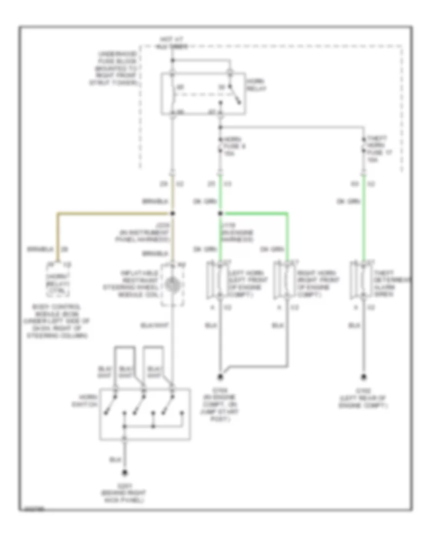
HORN
Horn Wiring Diagram for Pontiac G8 GT 2009
List of elements for Horn Wiring Diagram for Pontiac G8 GT 2009:
- Body control module (bcm) (under left side of dash, right of steering column)
- G102 (left rear of engine compt)
- G104 (in engine compt, on jump start post)
- G201 (behind right kick panel)
- Horn fuse 8 15a
- Horn relay
- Horn relay ctrl
- Horn switch
- Hot at all times
- Inflatable restraint steering wheel module coil
- J119 (in engine harness)
- J236 (in instrument panel harness)
- Left horn (left front of engine compt)
- Right horn (right front of engine compt)
- Theft deterrent alarm siren
- Theft horn fuse 17 10a
- Underhood fuse block (mounted to right front strut tower)
INSTRUMENT CLUSTER
Instrument Cluster Wiring Diagram for Pontiac G8 GT 2009
List of elements for Instrument Cluster Wiring Diagram for Pontiac G8 GT 2009:
- (behind right kick panel) g201
- (in fuel tank harness) j330
- (on park brake assembly) park brake switch
- (or 2705)
- (or 2755)
- (or 470)
- (under left side of dash, right of steering column)
- 3.6l
- 5v ref 1
- 5v ref 1 (6.0l & 6.2l) 5v ref 2 (3.6l)
- 6.0l & 6.2l
- Abs ind
- Acc run
- Air bag ind
- Battery
- Body control module (bcm)
- Brake fluid level switch (in brake fluid reservoir)
- Brake ind
- Brk warning ind ctrl
- Charging ind
- Computer data lines system
- Computer data lines system mirrors system
- Coolant temp gauge
- Cruise ind
- Disable sw sig
- Driver information center (dic)
- Ect sens sig
- Engine control module (ecm) (right side of engine compt)
- Engine controls system
- Engine coolant temperature (ect) sensor (3.6l: left side of engine) (except 3.6l: left front of engine)
- Engine oil level & temperature sensor (3.6l: left front of oil pan) (except 3.6l: right side of oil pan)
- Engine oil pressure (eop) sensor (3.6l: top left front of engine) (except 3.6l: top rear of engine)
- Fog lamp ind
- Fuel level gauge
- Fuel lvl sens
- Fuel press sig (3.6l)
- Fuel pump & sender assembly (in fuel tank)
- Fuel tank pressure (ftp) sensor
- Fuel tank vapour press (6.0l & 6.2l)
- G102 (left rear of engine compt)
- Ground
- Hi spd data +
- Hi spd data -
- High beam ind
- Hot at all times
- Ignition 1 voltage
- Ignition switch
- Inst/disp/ rfa/dlc fuse 5 10a
- Instrument panel cluster (ipc)
- J123
- J215
- J221
- Km/h mph gauge
- Left steering wheel 1
- Left steering wheel 2
- Left turn ind
- Lo spd ser
- Lo spd serial data
- Logic
- Low oil pressure ind
- Low ref
- Low tire pressure ind
- Malfunction ind
- Mil ctrl
- Mirrors system
- Off
- Oil lvl sw sig
- Oil press sens
- Oil temp sens
- Pnk
- Prk brk sw
- Rear fuse block (left side of rear compt)
- Right steering wheel 1
- Right steering wheel 2
- Right turn ind
- Rpm gauge
- Seat belt ind
- Sec ind ctrl
- Secondary fuel level sensor (in fuel tank)
- Security ind
- Security ind ctrl
- Sound systems
- Start
- Steering wheel ctrl
- Suppression ind ctrl
INTERIOR LIGHTS
Courtesy Lamps Wiring Diagram for Pontiac G8 GT 2009
List of elements for Courtesy Lamps Wiring Diagram for Pontiac G8 GT 2009:
- (behind right kick panel) g201
- (in instrument panel harness) j216
- Ajar switch
- Batt +
- Bcm fuse 9 10a
- Body control module (bcm) (under left side of dash, right of steering column)
- Computer data lines system
- Ctsy/trn sig rt frt fuse 5 15a
- Cylinder lamp
- Data bus +
- Data bus -
- Dome/reading lamps
- Driver door latch assembly (rear of driver door)
- Drvr ajar sw
- Front dome lamp
- G201 (behind right kick panel)
- G202 (behind left kick panel)
- G304 (behind right kick panel)
- G305 (behind left kick panel)
- Hot at all times
- I/p compartment lamp
- I/p compartment lamp switch
- Ignition key
- Inadv/ pwr/led fuse 4 15a
- Instrument panel fuse block (behind left kick panel)
- J324
- J327 (in headliner harness)
- J339
- Left rear door latch assembly (rear of left rear door)
- Left sunshade
- Lp sply volt
- Lp sw sig
- Panel harness) j202
- Pass ajar sw
- Passenger door latch assembly (rear of front passenger door)
- Rear compartment courtesy lamp
- Rear compartment lid latch assembly (center rear of lid)
- Rear dome lamp
- Right rear door latch assembly (rear of right rear door)
- Right sunshade
- Sply volt
- W/ electric sliding glass sunroof
- W/o electric sliding glass sunroof
Instrument Illumination Wiring Diagram for Pontiac G8 GT 2009
List of elements for Instrument Illumination Wiring Diagram for Pontiac G8 GT 2009:
- (in instrument panel harness) j208
- Auto
- Automatic transmission shift lever
- Batt +
- Bcm fuse 9 10a
- Body control module (bcm) (under left side of dash, right of steering column)
- Center console multi-function switch
- Cigar lighter
- Cigar lighter console
- Computer data lines system
- Data bus +
- Data bus -
- Dimming ctrl
- Dome/ reading lamps
- Door lock/ window switch
- Driver information center (dic)
- G201 (behind right kick panel)
- G305 (behind left kick panel)
- G310 (top of steering column)
- Head
- Headlamp & panel dimmer switch
- Hot at all times
- Hot w/ ign relay energized
- Htd seat/ onstar ign fuse 38 10a
- Hvac control module (right side of hvac unit)
- I/p fuse block (behind left kick panel)
- Inadv/ pwr/led fuse 4 15a
- Inflatable restraint steering wheel module coil
- Instrument panel cluster (ipc)
- Int lamps fuse 11 15a
- J222
- J240
- J324
- Lo spd gmlan serial data
- Logic
- Nca
- Off
- Park
- Park lp sw on sig
- Park rly ctrl
- Prk lamp relay 18
- Radio
- Sply volt
- Steering wheel control switch
- Sw down
- Sw up
- Swc bklt fuse 23 2a
- Underhood fuse block (mounted to right front strut tower)
- W/ electric sliding glass sunroof
NAVIGATION
Navigation Wiring Diagram for Pontiac G8 GT 2009
List of elements for Navigation Wiring Diagram for Pontiac G8 GT 2009:
- Audio sig (+)
- Audio sig (-)
- Audio sig mute
- Batt pos vol
- Cellular & navigation antenna
- Cellular signal
- Cellular telephone microphone
- Coax
- Computer data lines system
- Drain wire
- G303 (behind right center of dash)
- Gmlan serial data
- Ground
- Hot at all times
- J209
- Onstar fuse 8 10a
- Radio
- Rear fuse block (left side of rear compt)
- Serial data bus+
- Serial data bus-
- Vcim batt low ref
- Vcim batt pwr
- Vehicle communication interface module (vcim)
- Vehicle communication interface module (vcim) battery
- Voice low ref
- Voice sig
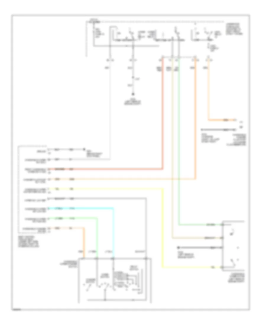
POWER DISTRIBUTION
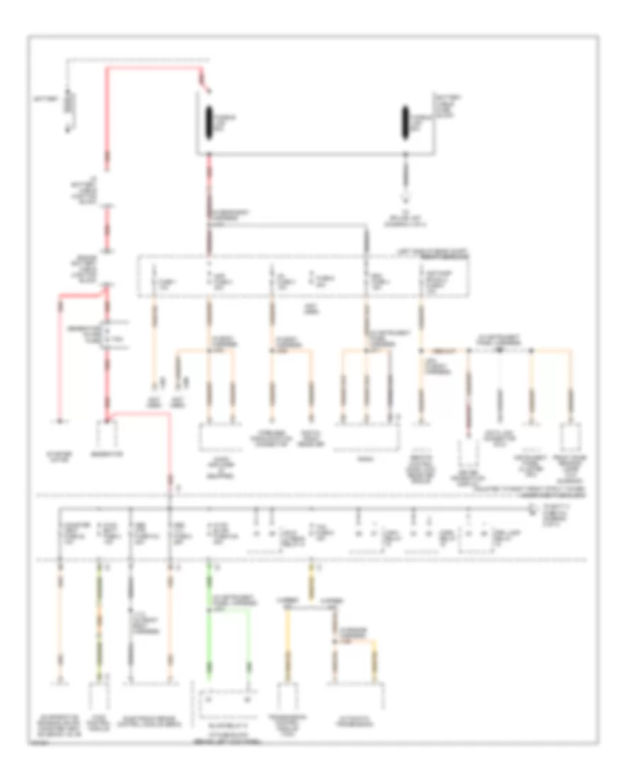
Power Distribution Wiring Diagram (1 of 4) for Pontiac G8 GT 2009
List of elements for Power Distribution Wiring Diagram (1 of 4) for Pontiac G8 GT 2009:
- (in body harness) j302
- (in body harness) j402
- (in engine harness) j128
- (in instrument panel harness) j211
- (in instrument panel harness) j221
- (in instrument panel harness) j223
- (in rear body harness) j410
- (left side of rear compt) rear fuse block
- (mounted to right front strut tower) underhood fuse block
- (not used)
- 175a
- 5 speed a/t
- 6 speed a/t
- Abs mtr fuse fu3 40a
- Abs vlv fuse 5 25a
- Amp fuse 2 30a
- Audio amplifier (if equipped)
- Automatic transmission
- Battery
- Battery cable fuse block
- Blwr relay 9
- Canister vent fuse 22 10a
- Data link connector (dlc)
- Digital radio receiver
- Driver information display
- Electronic brake control module (ebcm)
- Engine battery cable junction block
- Evaporative emission (evap) canister vent solenoid valve
- Front dome/ reading lamps (w/o sunroof)
- Fuse 1 10a
- Fuse 6 20a
- Fusible link 60a
- Generator
- Generator inline fuse
- Hdlp lo beam relay 6
- Horn relay
- Hvac batt fuse 2 10a
- Hvac blwr fuse fu9 40a
- Hvac control module
- I/p battery cable junction block
- I/p fuse block (behind left kick panel)
- Inst/disp rfa/dlc fuse 5 10a
- Instrument panel cluster (ipc)
- J112 (in front body harness)
- J404 (in body harness)
- Prk lamp relay
- Radio
- Rdo fuse 4 15a
- Red
- Remote control door lock receiver (rcdlr)
- Starter motor
- Tcm fuse 9 15a
- To batt 3 fuse fu4 (diagram 2 of 4)
- To splice j407 (diagram 4 of 4)
- Transmission control module (tcm)
- Wireless communication connector
- Wsw relay
- X206
- X403
- Xm fuse 3 10a
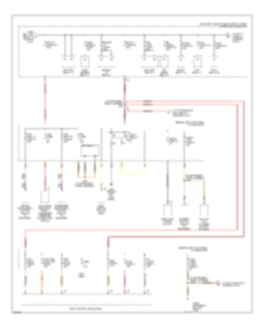
Power Distribution Wiring Diagram (2 of 4) for Pontiac G8 GT 2009
List of elements for Power Distribution Wiring Diagram (2 of 4) for Pontiac G8 GT 2009:
- (behind left kick panel) i/p fuse block
- (in instrument panel harness) j219
- (in instrument panel harness) j220
- (in instrument panel harness) j230
- (mounted to right front strut tower) underhood fuse block
- (not used)
- Accy relay
- Aos fuse 5a
- Backup lp fuse 3 15a
- Backup lp relay 4
- Batt 2 fuse fu7 50a
- Batt 3 fuse fu4 50a
- Bcm fuse 9 10a
- Body control module (bcm)
- Comm enable fuse 1 10a
- Comm enable relay 2
- Crank relay 12
- Ctsy/trn sig rt frt fuse 5 15a
- Dlis/ theft dtrnt fuse 12 2a
- Door lock/ window switch
- Driver heated seat control module (if equipped)
- Drl fuse 15a
- Drl relay 11
- Fan 1 fuse fu10 30a
- Fan 1 relay 17
- Fan 2 fuse fu12 30a
- Fan 3 relay 20
- Fog lamp fuse 4 15a
- Fog lamp relay 5
- From prk lamp relay 18 (diagram 1 of 4)
- Fuse 10a
- G202 (behind left kick panel)
- Htd/ seat lt fuse 19 15a
- Htd/ seat rt fuse 20 15a
- Ignition lock cylinder control solenoid
- Inflatable restraint front passenger presence system (pps) module
- Int lamps fuse 11 15a
- J228 (in instrument panel harness)
- Osrvm fuse 15 2a
- Passenger heated seat control module (if equipped)
- Pwr trn relay 13
- Rr defog fuse fu2 40a
- Rr defog relay 8
- S/roof atsl fuse 16 10a
- Stop fuse 10 15a
- Strtr fuse fu8 40a
- Sunroof control module (if equipped)
- Theft deterrent module (tdm)
- To batt 1 fuse fu5 (diagram 3 of 4)
- To i/p fuse block rap 2 relay 7 (diagram 3 of 4)
- To ignition switch (diagram 4 of 4)
- Trn sig rt fuse 6 15a
- Trn/ sig lt fuse 8 15a
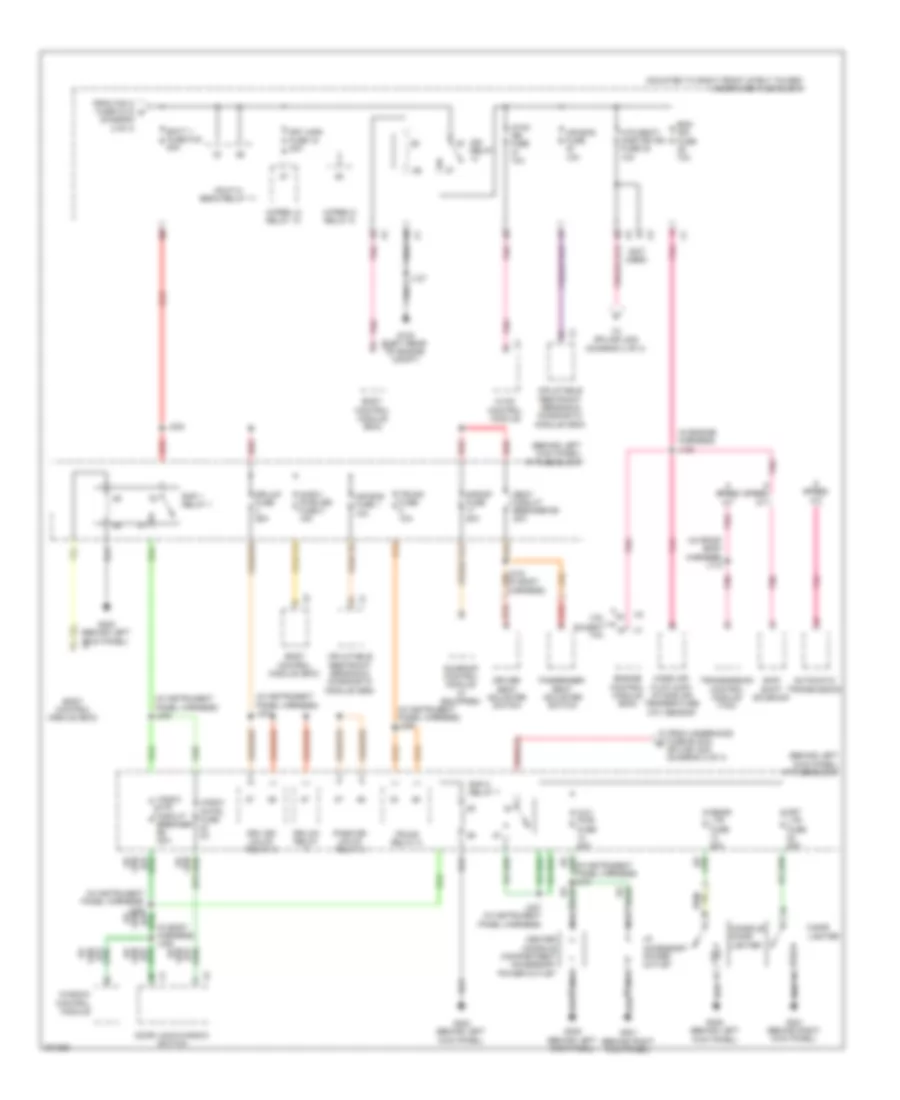
Power Distribution Wiring Diagram (3 of 4) for Pontiac G8 GT 2009
List of elements for Power Distribution Wiring Diagram (3 of 4) for Pontiac G8 GT 2009:
- (behind left kick panel) i/p fuse block
- (diagram 2 of 4)
- (in body harness) j309
- (in engine harness) j120
- (in front body harness) j110
- (in instrument panel harness) j210
- (in instrument panel harness) j226
- (in instrument panel harness) j231
- (in instrument panel harness) j233
- (mounted to right front strut tower) underhood fuse block
- (not used)
- 3.6l
- Air bag fuse 1 10a
- Air bag fuse 10a
- Automatic transmission
- Aux pwr fuse 20a
- Batt 1 fuse fu5 50a
- Body control module (bcm)
- Center console compartment accessory power outlet
- Cigar lighter
- Console cigar lighter
- Door lock/window switch
- Dr/lck fuse 25a
- Dr/lck relay
- Driver seat adjuster switch
- Drv dr/ unlck relay 6
- Eng ign fuse 10a
- Engine control module (ecm)
- Except 3.6l
- From fan 2 fuse fu12 c
- From underhood fuse block splice j230 (diagram 2 of 4)
- Frt ltr fuse 20a
- Frt wpr fuse 15 30a
- G102 (left rear of engine compt)
- G201 (behind right kick panel)
- G202 (behind left kick panel)
- G305 (behind left kick panel)
- Hdlp hi beam relay 11
- Htd seat/ onstar ign fuse 38 10a
- Hvac control module
- Hvac ign fuse 10a
- I/p accessory power outlet
- Ign relay
- Inadv/ pwr/led fuse 4 15a
- Inflatable restraint sensing & diagnostic module (sdm)
- J127
- J227 (in instrument panel harness)
- J232
- Mass air flow (maf) intake air temperature (iat) sensor
- Nca
- Pass dr/ unlck relay 3
- Passenger seat adjuster switch
- Pnk
- Pnk speed m/t
- Rap 1 relay 1
- Rap 2 relay 7
- Rear/ ltr fuse 20a
- Red
- S/roof fuse 20a
- Seat circuit breaker b3 20a
- Skip shift solenoid
- Speed a/t
- Sunroof control module (if equipped)
- To splice j222 (diagram 4 of 4)
- Transmission control module (tcm)
- Trunk fuse 10a
- Trunk relay 5
- Window control module
- Wiper hi relay 9
- Wiper lo relay 10
- Wndw cntrl fuse 2a
- Wndw mtr circuit breaker b2 20a
Power Distribution Wiring Diagram (4 of 4) for Pontiac G8 GT 2009
List of elements for Power Distribution Wiring Diagram (4 of 4) for Pontiac G8 GT 2009:
- (3.6l)
- (except 3.6l)
- (in instrument panel harness) j215
- (in instrument panel harness) j217
- (in instrument panel harness) j222
- (in rear body harness) j407
- (left side of rear compt) rear fuse block
- (not used)
- Acc run
- Body control module (bcm)
- Center console multi-function switch (w/ front seat heater)
- Driver heated seat control module
- Ecm batt fuse 10 15a
- Engine control module (ecm)
- From battery cable fuse block (diagram 1 of 4)
- From i/p fuse block splice j220 (diagram 2 of 4)
- From underhood fuse block htd seat/onstar ign fuse (diagram 3 of 4)
- Fuel pump fuse 20a
- Fuel relay
- Fuse 10a
- Fuse 30a
- Headlamp & panel dimmer switch
- I/p fuse block (behind left kick panel)
- Ignition switch
- Inside rearview mirror (isrvm)
- Instrument panel cluster (ipc)
- J237 (in body harness)
- Key in ignition switch
- Off
- Onstar fuse 10a
- Passenger heated seat control module
- Pnk
- Rvc snsr fuse 11 7.5a
- Start
- Theft deterrent module (tdm)
- Vehicle communication interface module (vcim)
- W/ front seat heater
- X404
POWER DOOR LOCKS
Power Door Locks Wiring Diagram for Pontiac G8 GT 2009
List of elements for Power Door Locks Wiring Diagram for Pontiac G8 GT 2009:
- (behind left kick panel) g305
- (in body harness) j306
- (in body harness) j317
- (in body harness) j320
- 87a
- Ajar sw sig
- Body control module (bcm) (under left side of dash, right of steering column)
- Computer data lines system
- Door lock/ window switch
- Dr lck ctrl
- Dr unlk
- Dr unlk cntrl
- Dr/lck fuse 3 25a
- Dr/lck relay 2
- Driver door latch assembly (rear of driver front door)
- Drv dr ajar sw sig
- Drv dr lk sw
- Drv dr lk sw lk sig
- Drvr dr/unlck relay 6
- Exterior lights system
- Front passenger door latch assembly (rear of passenger front door)
- Fuel door release actuator
- Fuse suply volt
- G202 (behind left kick panel)
- G304 (behind right kick panel)
- G305 (behind left kick panel)
- G407 (under center of rear parcel shelf)
- Ground
- Hood ajar switch
- Horn relay ctl
- Horns system
- Hot at all times
- Inst/disp/ rfa/dlc fuse 5 10a
- Instrument panel fuse block (behind left kick panel)
- J231
- J339
- J404
- Left rear door latch assembly (rear of left rear door)
- Liftgate
- Pass dr/unlck relay 3
- Pass frt dr
- Pk lamp rly ctl
- Pnk
- Pwr dr lck
- Pwr dr unlk
- Rear compartment lid latch assembly (center rear of lid)
- Rear fuse block (left side of rear compt)
- Remote control door lock receiver (rcdlr)
- Right rear door latch assembly (rear of right rear door)
- Serial data
- Suply volt
- Underhood fuse block (mounted to right front strut tower)
- Unlk sig
- X4 hood ajar sw
- X5 hood clsd sw
- X6 ajar sig
- X7 fuse suply volt
POWER MIRRORS
Automatic Day/Night Mirror Wiring Diagram for Pontiac G8 GT 2009
List of elements for Automatic Day/Night Mirror Wiring Diagram for Pontiac G8 GT 2009:
- (usa)
- (canada)
- (usa)
- Air bag off ind
- Air bag on ind
- Automatic day/night mirror
- Backup lamp relay control
- Backup lp fuse 3 15a
- Backup lp relay 4
- Body control module (bcm) (under left side of dash, right of steering column)
- Computer data lines system
- Emergency ind
- Emergency switch
- Exterior lights system
- G202 (behind left kick panel)
- High speed gmlan serial data bus+
- High speed gmlan serial data bus-
- Hot at all times
- Hot w/ ign relay 14 energized
- Htd seat/ onstar ign fuse 38 10a
- I/p module disable switch signal
- I/p module suppression indicator control
- Ign
- Inside rearview mirror
- Instrument panel cluster (ipc)
- J222
- J238 (in body harness)
- Keypad green led ind
- Keypad green led signal
- Keypad red led ind
- Keypad red led signal
- Keypad signal
- Left turn ind
- Lo spd data
- Logic
- Low speed gmlan serial data
- Off ind
- On ind
- Onstar button assembly
- Onstar ind
- Onstar switch
- Passenger air bag ind (usa)
- Phone ind
- Phone switch
- Right turn ind
- Underhood fuse block (mounted to right front strut tower)
- Vehicle communication interface module (vcim)
Power Mirrors Wiring Diagram for Pontiac G8 GT 2009
List of elements for Power Mirrors Wiring Diagram for Pontiac G8 GT 2009:
- Door lock/ window switch
- Down
- Driver outside rearview mirror (on driver front door)
- G305 (behind left kick panel)
- Hot w/ accy relay 8 energized
- Instrument panel fuse block (behind left kick panel)
- J307 (in body harness)
- Left
- Left/ right
- Nca
- Osrvm fuse 15 2a
- Passenger outside rearview mirror (on passenger front door)
- Right
- Up/ down
POWER SEATS
Driver Power Seat Wiring Diagram for Pontiac G8 GT 2009
List of elements for Driver Power Seat Wiring Diagram for Pontiac G8 GT 2009:
- Bwd
- Down
- Driver seat adjuster switch
- Driver seat front vertical motor
- Driver seat horizontal motor (6-way driver power seat adjuster)
- Driver seat rear vertical motor
- Front vertical
- Fwd
- G305 (behind left kick panel)
- Horizontal
- Hot at all times
- Instrument panel fuse block (behind left kick panel)
- J315
- Rear vertical
- Seat circuit breaker b3 20a
Heated Seats Wiring Diagram for Pontiac G8 GT 2009
List of elements for Heated Seats Wiring Diagram for Pontiac G8 GT 2009:
- (behind right kick panel) g304
- Anti-lock brakes system
- Batt pos
- Body control module (bcm) (under left side of dash, right of steering column)
- Center console multi-function switch
- Driver back heated seat element
- Driver cushion heated seat element
- Driver heated seat control module (under driver's seat)
- Drv hi/lo sig
- G201 (behind right kick panel)
- G304 (behind right kick panel)
- G305 (behind left kick panel)
- Ground
- Hi temp ind ctrl
- Hot at all times
- Hot w/ ign relay 14 energized
- Htd seat/ onstar ign fuse 38 10a
- Htd/ seat lt fuse 19 15a
- Htd/ seat rt fuse 20 15a
- Ign
- Instrument panel fuse block (behind left kick panel)
- Interior lights system
- Intermediate sig
- J222
- J237
- J322
- J323
- J347
- J348
- Lo temp ind ctrl
- Passenger back heated seat element
- Passenger cushion heated seat element
- Passenger heated seat control module (under front passenger's seat)
- Pnk
- Sens sig
- Tan
- Underhood fuse block (mounted to right front strut tower)
Passenger Power Seat Wiring Diagram for Pontiac G8 GT 2009
List of elements for Passenger Power Seat Wiring Diagram for Pontiac G8 GT 2009:
- Bwd
- Down
- Front vertical
- Fwd
- G304 (behind right kick panel)
- Horizontal
- Hot at all times
- Instrument panel fuse block (behind left kick panel)
- J315
- Passenger seat adjuster switch
- Passenger seat front vertical motor
- Passenger seat horizontal motor (6-way passenger power seat adjuster)
- Passenger seat rear vertical motor
- Rear vertical
- Seat circuit breaker b3 20a
- Tan
POWER TOP/SUNROOF
Power Top/Sunroof Wiring Diagram for Pontiac G8 GT 2009
List of elements for Power Top/Sunroof Wiring Diagram for Pontiac G8 GT 2009:
- G201 (behind right kick panel)
- Gnd
- Hot at all times
- Hot w/ accy relay energized
- Ign 1
- Instrument panel fuse block (behind left kick panel)
- J219
- J325
- Logic
- S/roof atsl fuse 16 10a
- S/roof fuse 17 20a
- Sun roof sw 1
- Sun roof sw 2
- Sun roof sw 3
- Sun roof sw 4
- Sunroof control module (center front of roof)
- Sunroof motor
- Sunroof switch
POWER WINDOWS
Power Windows Wiring Diagram for Pontiac G8 GT 2009
List of elements for Power Windows Wiring Diagram for Pontiac G8 GT 2009:
- (behind left kick panel) g305
- (behind right kick panel) g304
- Door lock/ window switch
- Driver window motor (in driver front door)
- Front passenger window motor (in passenger front door)
- Ground
- Hot w/ rap relay energized
- I/p fuse block
- J229
- J305 (in body harness)
- J309
- Left rear window motor (in left rear passenger door)
- Left rear window switch
- Lock out
- Mtr lh frt up ctrl
- Mtr rh frt down ctrl
- Mtr rh frt up ctrl
- Rap sply vol
- Right rear window motor (in right rear passenger door)
- Right rear window switch
- Sw lh frt up sig
- Sw rh frt down ctrl
- Sw rh frt down sig
- Sw rh frt up sig
- Window control module (right kick panel)
- Wndw cntrl fuse 24 2a
- Wndw mtr circuit breaker b2 20a
RADIO
Radio Wiring Diagram, Except UWP for Pontiac G8 GT 2009
List of elements for Radio Wiring Diagram, Except UWP for Pontiac G8 GT 2009:
- (behind right center of dash) g303
- (in instrument panel harness) j203
- (in instrument panel harness) j225
- Aud sig mute
- Audio sig (-)
- Batt pos vol
- Cellular, navigation & digital radio antenna
- Center i/p speaker
- Coax
- Computer data lines system
- Digital radio receiver (if equipped)
- Down
- G303
- G310 (top of steering column)
- Gmlan serial data
- Ground
- Hot at all times
- Inflatable restraint steering wheel module coil
- Instrument panel cluster (ipc)
- J204 (in instrument panel harness)
- J209
- J211
- J224 (in instrument panel harness)
- J302
- Left front speaker
- Left front tweeter speaker
- Left rear speaker
- Lf spkr out (+)
- Lf spkr out (-)
- Lh radio aud out
- Lh steering wheel 1
- Lh steering wheel 2
- Low ref
- Lr spkr out (+)
- Lr spkr out (-)
- Mute
- Navigation system
- Nca
- Radio
- Radio antenna
- Radio control
- Radio/ hvac control
- Rdo fuse 4 15a
- Rear fuse block (left side of rear compt)
- Remote radio out (-)
- Remote radio rh aud
- Remote radio sig
- Rf spkr out (+)
- Rf spkr out (-)
- Rh radio aud out
- Rh steering wheel 1
- Rh steering wheel 2
- Right front speaker
- Right front tweeter speaker
- Right rear speaker
- Rr spkr out (+)
- Rr spkr out (-)
- Srce
- Steering wheel control switch
- Steering wheel ctrl
- Telephone aud sig (+)
- Trip/ fuel
- Voice
- Xm fuse 3 10a
Radio Wiring Diagram, UWP for Pontiac G8 GT 2009
List of elements for Radio Wiring Diagram, UWP for Pontiac G8 GT 2009:
- (behind right center of dash) g303
- (in body harness) j313
- Amp fuse 2 30a
- Aud sig mute
- Audio amplifier (left side of rear compartment)
- Audio sig (-)
- Batt pos vol
- Cellular, navigation & digital radio antenna
- Center i/p speaker
- Coax
- Computer data lines system
- Digital radio receiver (if equipped)
- Down
- Frt spkr out (+)
- G303
- G305 (behind left kick panel)
- G310 (top of steering column)
- Gmlan serial data
- Ground
- Hot at all times
- Inflatable restraint steering wheel module coil
- Instrument panel cluster (ipc)
- J209
- J211
- J302
- J312 (in body harness)
- J402
- J404 (in body harness)
- J405
- Left front speaker
- Left front tweeter speaker
- Left rear speaker
- Left subwoofer speaker
- Lf spkr out (+)
- Lf spkr out (-)
- Lh radio aud out
- Lh steering wheel 1
- Lh steering wheel 2
- Lh subwoofer out (+)
- Lh subwoofer out (-)
- Low ref
- Lr spkr out (+)
- Lr spkr out (-)
- Mute
- Navigation system
- Nca
- Radio
- Radio antenna
- Radio control
- Radio/ hvac control
- Rdo fuse 4 15a
- Rear fuse block (left side of rear compt)
- Remote radio out (-)
- Remote radio rh aud
- Remote radio sig
- Rf spkr out (+)
- Rf spkr out (-)
- Rh radio aud out
- Rh steering wheel 1
- Rh steering wheel 2
- Rh subwoofer out (+)
- Rh subwoofer out (-)
- Right front speaker
- Right front tweeter speaker
- Right rear speaker
- Right subwoofer speaker
- Rr spkr out (+)
- Rr spkr out (-)
- Srce
- Steering wheel control switch
- Steering wheel ctrl
- Telephone aud sig (+)
- Trip/ fuel
- Voice
- Xm fuse 3 10a
SHIFT INTERLOCK
Ignition Lock Solenoid Wiring Diagram for Pontiac G8 GT 2009
List of elements for Ignition Lock Solenoid Wiring Diagram for Pontiac G8 GT 2009:
- Automatic transmission shift lever
- G201 (behind right kick panel)
- Hot w/ accy relay 8 energized
- I/p fuse block (behind left kick panel)
- Ignition lock cylinder control solenoid
- J219
- S/roof atsl fuse 16 10a
Shift Interlock Wiring Diagram for Pontiac G8 GT 2009
List of elements for Shift Interlock Wiring Diagram for Pontiac G8 GT 2009:
- 3.6l
- 5 speed a/t
- 5volt ref
- 6 speed a/t
- 6.0l & 6.2l
- A/t shift lock sol
- Automatic transmission (right rear of transmission)
- Automatic transmission internal mode switch (ims)
- Automatic transmission shift lever
- Automatic transmission shift lock control solenoid
- Battery
- Body control module (bcm) (under left side of dash, right of steering column)
- Brake pedal position (bpp) sensor (top of brake pedal assembly)
- Computer data lines system
- Control solenoid valve assembly
- Data bus (+)
- Data bus (-)
- Engine control module (ecm) (right side of engine compt)
- G106 (right front of engine block)
- G201 (behind right kick panel)
- Gnd
- High speed data bus+
- High speed data bus-
- Hot at all times
- Instrument panel fuse block (behind left kick panel)
- Int lamps fuse 11 15a
- J122
- Low ref
- Nca
- P/n sig
- St lp sw sig
- Transmission control module (tcm)
STARTING/CHARGING
Charging Wiring Diagram for Pontiac G8 GT 2009
List of elements for Charging Wiring Diagram for Pontiac G8 GT 2009:
- (behind right kick panel)
- (in rear compt, on latch plate) g409
- 175a
- 3.6l
- 5v ref
- 6.0l & 6.2l
- Batt pos vol
- Battery
- Battery cable
- Battery current sensor (left side of rear compt)
- Body control module (bcm) (under left side of dash, right of steering column)
- Charge ind
- Computer data lines system
- Current sig
- Cycle sig
- Driver information center (dic)
- Engine battery cable junction block
- Engine control module (ecm) (right side of engine compt)
- Fuse block
- G201
- G401 (rear compt, on left rear beam)
- Generator
- Generator inline fuse
- Gnd
- Hot at all times
- Hs bus +
- Hs bus -
- I/p battery cable junction block
- Inst/disp/ rfa/dlc fuse 5 10a
- Instrument panel cluster (ipc)
- J221
- J412
- Lo ref
- Lo spd gmlan
- Logic
- Pnk
- Rear fuse block (left side of rear compt)
- Red
- Rvc snsr fuse 11 7.5a
- Starting circuit
- Turn on sig
Starting Wiring Diagram for Pontiac G8 GT 2009
List of elements for Starting Wiring Diagram for Pontiac G8 GT 2009:
- 175a
- 3.6l
- 5 speed
- 5 speed a/t
- 6 speed
- 6 speed a/t
- 6.0l & 6.2l
- Acc
- Automatic transmission (right rear of transmission)
- Automatic transmission internal mode switch (ims)
- Battery
- Battery cable
- Body control module (bcm) (under left side of dash, right of steering column)
- Computer data lines system
- Control solenoid valve assembly
- Crank relay 12
- Engine battery cable junction block
- Engine control module (ecm) (right side of engine compt)
- F x1
- Fuse block
- G102 (left rear of engine compt)
- G106 (right front of engine block)
- G401 (rear compt, on left rear beam)
- Generator
- Generator inline fuse
- Hs bus+
- Hs bus-
- I/p battery cable junction block
- Ignition switch
- Internal mode switch (ims)
- J122
- J127
- Lock
- P/n
- P/n sig
- Red
- Resistor lo ref
- Resistor sig
- Run
- Start
- Starter motor
- Str rly ctrl
- Strtr fuse fu8 40a
- Transmission control module (tcm)
- Underhood fuse block (mounted to right front strut tower)
SUPPLEMENTAL RESTRAINTS
Supplemental Restraints Wiring Diagram (1 of 3) for Pontiac G8 GT 2009
List of elements for Supplemental Restraints Wiring Diagram (1 of 3) for Pontiac G8 GT 2009:
- (in left "c" pillar) left inflatable restraint roof rail module
- (in right "b" pillar) right inflatable restraint side impact module
- (in right "c" pillar) right inflatable restraint roof rail module
- (under center console)
- Air bag fuse 10a
- Air bag fuse f10 10a
- Battery positive volt
- Computer data lines system
- Driver inflatable restraint seat position sensor
- Driver seat belt switch
- G308
- G308 (under center console)
- Gnd
- Ground
- High ctrl
- Hot at all times
- Hot w/ ign relay energized
- I/p fuse block (behind left kick panel)
- Ignition 1 voltage
- Inflatable restraint sensing & diagnostic module (sdm)
- J300 (in body harness)
- J301 (in body harness)
- J314
- Left inflatable restraint side impact sensor (sis) (base of left "b" pillar)
- Lf high ctrl
- Lf low ctrl
- Lh high ctrl
- Lh low ctrl
- Lh low reference
- Lh seat belt sw
- Lh signal
- Lh signal sensor
- Low ctrl
- Low reference
- Low reference sensor
- Passenger inflatable restraint seat position sensor
- Passenger seat belt switch
- Pin shorting bars engaged
- Pnk
- Pnk b
- Position sensor
- Position sensor rtn
- Rf high ctrl
- Rf low ctrl
- Rh high ctrl
- Rh low ctrl
- Rh low reference
- Rh seat belt sw
- Rh signal
- Rh signal sensor
- Right inflatable restraint front end sensor (right front of engine compt)
- Right inflatable restraint side impact sensor (sis) (base of right "b" pillar)
- Serial data
- Shorting bar
- Signal
- Stage 1 high ctrl
- Stage 1 low ctrl
- Stage 2 high ctrl
- Stage 2 low ctrl
- Underhood fuse block (mounted to right front strut tower)
- When module connector is disconnected from harness: (shorting bars are connected between following connector & pins: x2: 1-2 & 3-4)
- X2 a
Supplemental Restraints Wiring Diagram (2 of 3) for Pontiac G8 GT 2009
List of elements for Supplemental Restraints Wiring Diagram (2 of 3) for Pontiac G8 GT 2009:
- Driver seat belt buckle pretensioner
- Driver seat belt retractor pretensioner (at left "b" pillar)
- Inflatable restraint i/p module (behind right side of dash)
- Inflatable restraint steering wheel module (under steering wheel horn pad)
- Inflatable restraint steering wheel module coil
- Passenger seat belt buckle pretensioner
- Passenger seat belt retractor pretensioner (at right "b" pillar)
- Pnk
- Shorting bar
- Tan
Supplemental Restraints Wiring Diagram (3 of 3) for Pontiac G8 GT 2009
List of elements for Supplemental Restraints Wiring Diagram (3 of 3) for Pontiac G8 GT 2009:
- (under center console)
- Air bag indicator
- Aos fuse 5a
- Bar shorting
- Computer data lines system
- Driver information center (dic) display
- G202 (behind left kick panel)
- G308
- G308 (under center console)
- Gnd
- Hot at all times
- Hot w/ ign relay energized
- Htd seat/ onstar ign fuse f38 10a
- I/p fuse block (behind left kick panel)
- I/p mod disable sw sig
- I/p mod suppression ind ctrl
- Inflatable restraint front passenger presence system (pps) sensor
- Inflatable restraint passenger presence system (pps) module
- Inside rearview mirror (isrvm)
- Instrument panel cluster (ipc)
- J314
- Left inflatable restraint front end sensor (left front of engine compt)
- Left inflatable restraint side impact module (base of left "b" pillar)
- Lo spd gmlan serial data
- Logic
- Nca
- Off ind
- On ind
- Passenger air bag ind (usa)
- Pps sply volt
- Seat belt indicator
- Shorting bar
- Underhood fuse block (mounted to right front strut tower)
TRANSMISSION
Transmission Wiring Diagram, 5 Speed A/T (1 of 2) for Pontiac G8 GT 2009
List of elements for Transmission Wiring Diagram, 5 Speed A/T (1 of 2) for Pontiac G8 GT 2009:
- A/t shift lock ctrl sol sply volt
- Acc wakeup serial data
- Auto
- Automatic transmission shift lever
- Batt pos volt
- Body control module (bcm) (under left side of dash, right of steering column)
- Clutch pres ctrl sol
- Computer data lines system
- Cruise control system
- Eng ign fuse 39 10a
- Exterior lights system
- G106 (right front of engine block)
- Gmlan serial data bus+
- Gmlan serial data bus-
- Gnd
- Hi spd serial data +
- Hot at all times
- Hot w/ ign relay 14 energized
- Ign 1 vol
- J110
- J122
- J218 (in instrument panel harness)
- Lo spd serial data
- Low ref
- Pc sol valve high ctrl
- Pc sol valve low ctrl
- Pnk
- Remote radio ctrl sply vol x1
- Select
- Shift sol a valve ctrl
- Shift sol b valve ctrl
- Shift sol valve 3 hi ctrl
- Stop lamp sw sig
- Tan
- Tcc pwm sol valve ctrl
- Tcm fuse 9 15a
- Tft sensor signal
- Trans range sw sig a
- Trans range sw sig b
- Trans range sw sig c
- Trans range sw sig p
- Trans turbine spd sw lo
- Trans turbine spd sw sig
- Transmission control module (tcm) (right rear of engine compt)
- Underhood fuse block (mounted to right front strut tower)
- Vss high sig
- Vss low sig
Transmission Wiring Diagram, 5 Speed A/T (2 of 2) for Pontiac G8 GT 2009
List of elements for Transmission Wiring Diagram, 5 Speed A/T (2 of 2) for Pontiac G8 GT 2009:
- (in automatic transmission harness)
- (right front of engine block)
- Automatic transmission
- Bus+
- Bus-
- Cluster (ipc)
- Computer data lines system
- Driver information center (dic)
- Engine control module (ecm) (right side of engine compt)
- G106
- Gmlan
- Input shaft speed sensor (iss)
- Instrument panel
- Internal mode switch (ims)
- J122
- J143
- Logic
- Output shaft speed sensor (oss)
- Park/ntrl sig
- Pressure control (pc) solenoid valve
- Red
- Shift solenoid (ss) valve 1
- Shift solenoid (ss) valve 2
- Shift solenoid (ss) valve 3
- Tan
- Torque converter clutch (tcc) pulse width modulation (pwm) solenoid valve
- Transmission fluid temperature (tft) sensor
Transmission Wiring Diagram, 6 Speed A/T for Pontiac G8 GT 2009
List of elements for Transmission Wiring Diagram, 6 Speed A/T for Pontiac G8 GT 2009:
- (right front of engine block)
- Auto
- Automatic transmission
- Automatic transmission fluid pressure (tfp) manual valve position switch
- Automatic transmission fluid temperature (tft) sensor
- Automatic transmission internal mode switch (ims)
- Automatic transmission shift lever
- Batt+
- Body control module (bcm) (under left side of dash, right of steering column)
- Cluster (ipc)
- Computer data lines
- Computer data lines system
- Control solenoid valve assembly
- Cruise control system
- Data bus +
- Data bus -
- Driver information center (dic) display
- Eng ign fuse 39 20a
- Engine control module (ecm) (right side of engine compt)
- Exterior lights system
- G110
- Gmlan
- Gnd
- Hi spd serial data +
- Hi spd serial data -
- Hot at all times
- Hot w/ ign relay 14 energized
- Ign
- Ign 1 volt
- Input shaft speed sensor (iss)
- Instrument panel
- Iss low
- Iss/oss high
- J128
- J143 (in automatic transmission harness) b
- J218 (in instrument panel harness)
- Lo spd serial data
- Logic
- Low ref
- Oss low
- Output shaft speed sensor (oss)
- Pc 1 solenoid
- Pc 2 solenoid
- Pc 3 solenoid
- Pc 4 solenoid
- Pc 5 solenoid
- Pnk
- Pressure control (pc) solenoid valve 1
- Pressure control (pc) solenoid valve 2
- Pressure control (pc) solenoid valve 3
- Pressure control (pc) solenoid valve 4
- Pressure control (pc) solenoid valve 5
- Prk/ntrl sw
- Red
- Remote radio ctrl sply vol
- Select
- Shift solenoid (ss) valve 1
- Shift solenoid (ss) valve 2
- Ss 1
- Ss 2
- Start
- Stop lamp sw
- System
- Tcc solenoid
- Tcm fuse 9 15a
- Tfp 1
- Tfp 3
- Tfp 4
- Tfp 5
- Tft
- Torque converter clutch (tcc) pressure control (pc) solenoid valve
- Trans elec rang select sig
- Transmission control module (tcm)
- Trns range sig a
- Trns range sig b
- Trns range sig c
- Trns range sig p
- Underhood fuse block (mounted to right front strut tower)
- Wakeup serial
TRUNK, TAILGATE, FUEL DOOR
Trunk Release Wiring Diagram for Pontiac G8 GT 2009
List of elements for Trunk Release Wiring Diagram for Pontiac G8 GT 2009:
- (center rear of lid) rear compartment lid latch assembly
- (in rear compt, on latch plate) g409
- Body control module (bcm) (under left side of dash, right of steering column)
- Computer data lines system
- Driver information center (dic)
- G202 (behind left kick panel)
- Hot at all times
- Instrument panel cluster (ipc)
- Instrument panel fuse block (behind left kick panel)
- J226
- J412
- Liftgate ajar sw sig
- Logic
- Low speed gmlan serial data
- Rear compartment lid release switch
- Rear compt rly sw
- Serial data bus+
- Serial data bus-
- Trunk fuse 2 10a
- Trunk relay 5
- Trunk rly ctrl
WARNING SYSTEMS
Warning Systems Wiring Diagram for Pontiac G8 GT 2009
List of elements for Warning Systems Wiring Diagram for Pontiac G8 GT 2009:
- (in body harness) j300
- (under center console)
- Abs ind
- Acc run
- Air bag ind
- Auto
- Body control module (bcm) (under left side of dash, right of steering column)
- Brake fluid level sw
- Brake fluid level switch (in brake fluid reservoir)
- Brake ind
- Brake warning indicator lamp
- Charge ind
- Chime
- Computer data lines system
- Driver door latch assembly (rear of driver front door)
- Driver seat belt switch
- Drv dr ajar sw sig
- G102 (left rear of engine compt)
- G111 (right front of engine block)
- G201 (behind right kick panel)
- Head
- Headlamp & panel dimmer switch
- Headlamps off sig
- Headlamps on sig
- Hot at all times ignition switch
- Inflatable restraint sensing & diagnostic module (sdm)
- Instrument panel cluster (ipc)
- Key in ignition switch
- Left
- Left seat belt sw
- Left turn ind
- Logic
- Low ref
- Low spd gmlan serial data
- Low speed gmlan serial data
- Low tire pressure ind
- Lt trn sig sw
- Off
- Park
- Park brake sw sig
- Park brake switch (on park brake assembly)
- Park lp sw sig
- Right
- Right turn ind
- Rt trn sig sw
- Seat belt ind
- Serial data bus +
- Serial data bus -
- Start
- Turn signal/ multi-function switch
WIPER/WASHER
Wiper/Washer Wiring Diagram for Pontiac G8 GT 2009
List of elements for Wiper/Washer Wiring Diagram for Pontiac G8 GT 2009:
- 87a
- Body control module (bcm) (under left side of dash, right of steering column)
- Delay switch
- Front windshield
- Frt wpr fuse 15 30a
- G102 (left rear of engine compt)
- G104 (in engine compt, on jump start post)
- G201 (behind right kick panel)
- Ground
- Hot at all times
- J127
- Underhood fuse block (mounted to right front strut tower)
- Washer fluid pump rly ctrl
- Washer switch
- Windshield washer fluid pump (in washer fluid reservoir)
- Windshield washer sw sig x1
- Windshield wiper motor (left rear of engine compt)
- Windshield wiper motor park sw sig x4
- Windshield wiper sw high sig
- Windshield wiper sw low sig
- Windshield wiper sw sig 2
- Windshield wiper/washer switch
- Wiper high relay
- Wiper lo relay
- Wiper sw hi sig x5
- Wiper sw low ref
- Wiper switch
- Wsw fuse 21 15a
- Wsw relay

 Čeština
 Dansk
Dansk Deutsch
 Ελληνικά
 English
 English
 Español
 Suomi
Suomi Français
 Français
 עברית
עברית Hrvatski
 Magyar
 Italiano
 日本語
日本語 한국어
한국어 Nederlands
 Polski
 Português
 Português
 Română
 Русский
 Slovenščina
 Svenska
 Türkçe
 中文 (中国)