ACTIVE AERODYNAMICS
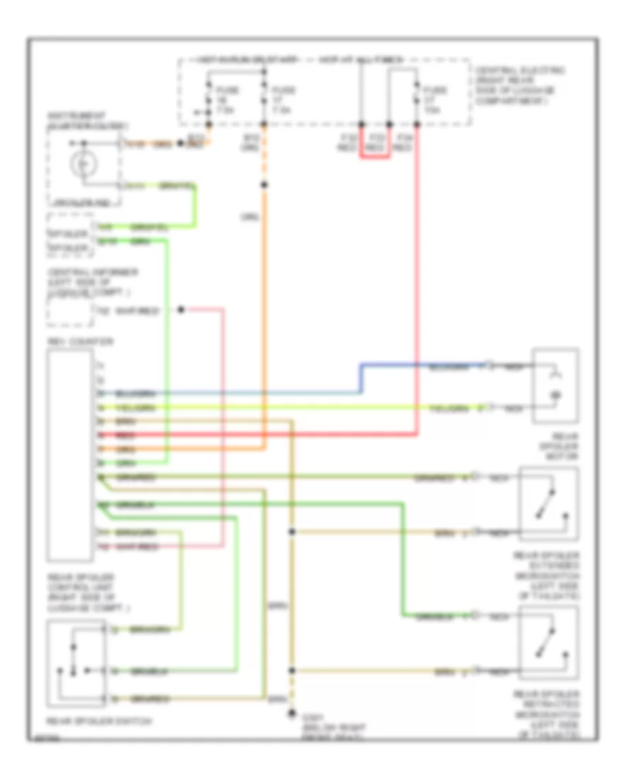
Active Aerodynamic Wiring Diagram, Early Production for Porsche 911 Carrera 4 1995
 https://portal-diagnostov.com/license.html
Automotive Electricians Portal FZCO
Automotive Electricians Portal FZCO
https://portal-diagnostov.com/license.html
https://portal-diagnostov.com/license.html
Automotive Electricians Portal FZCO
Automotive Electricians Portal FZCO
List of elements for Active Aerodynamic Wiring Diagram, Early Production for Porsche 911 Carrera 4 1995:
- 1/11
- 1/15
- 1/5
- 2/15
- B13
- Central electric (right rear side of luggage compartment)
- Central informer (left side of luggage compt.)
- F32 red
- F33 red
- F34 red
- Fuse 15a
- Fuse 7.5a
- G301 (below right front seat)
- Hot at all times
- Hot in run or start
- Instrument cluster (clock)
- Nca
- Rear spoiler control unit (right side of luggage compt.)
- Rear spoiler extended microswitch (left side of tailgate)
- Rear spoiler motor
- Rear spoiler retracted microswitch (left side of tailgate)
- Rear spoiler switch
- Red
- Rev counter
- Spoiler
- Spoiler ind.
Active Aerodynamic Wiring Diagram, Late Production for Porsche 911 Carrera 4 1995
List of elements for Active Aerodynamic Wiring Diagram, Late Production for Porsche 911 Carrera 4 1995:
- 1/11
- 1/15
- 1/5
- 2/15
- B13
- Central electric (right rear side of luggage compartment)
- Central informer (left side of luggage compt.)
- F32 red
- F33 red
- F34 red
- Fuse 15a
- Fuse 7.5a
- G301 (below right front seat)
- Hot at all times
- Hot in run or start
- Instrument cluster (clock)
- Nca
- Rear spoiler control unit (right side of luggage compt.)
- Rear spoiler extended microswitch (left side of tailgate)
- Rear spoiler motor
- Rear spoiler retracted microswitch (left side of tailgate)
- Rear spoiler switch
- Red
- Rev counter
- Spoiler
- Spoiler ind.
AIR CONDITIONING
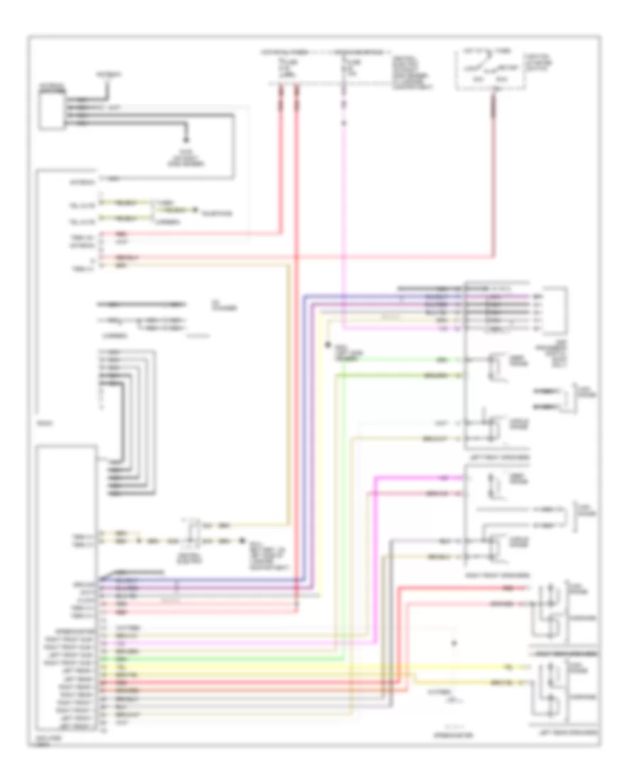
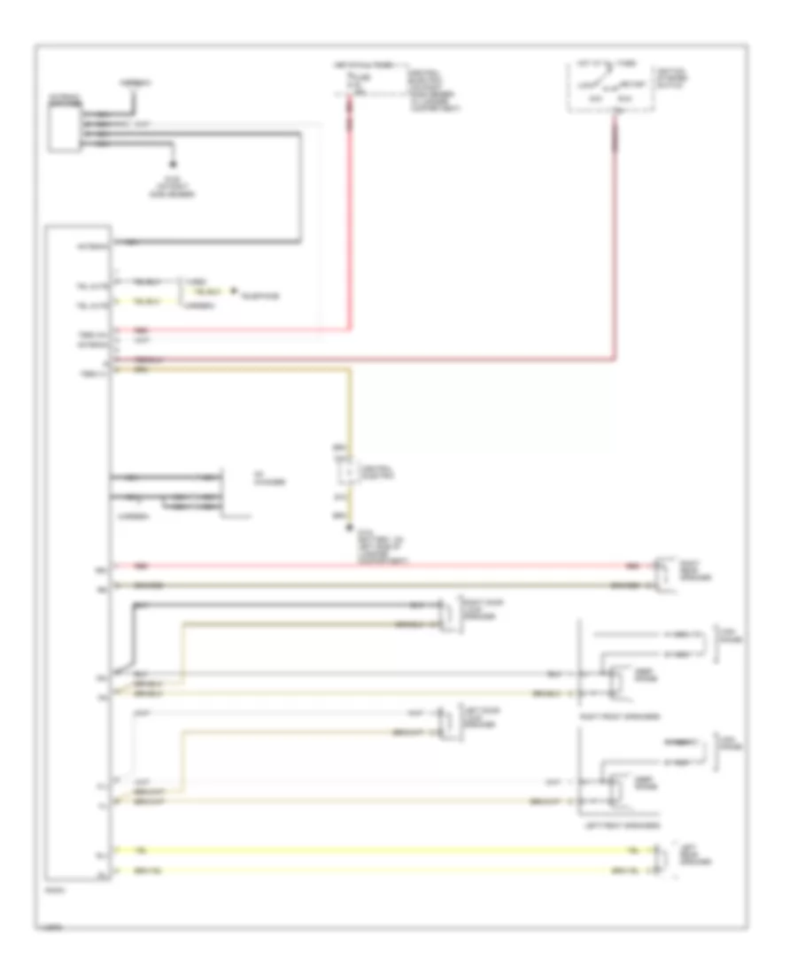
Air Conditioning Wiring Diagrams (1 of 2) for Porsche 911 Carrera 4 1995
List of elements for Air Conditioning Wiring Diagrams (1 of 2) for Porsche 911 Carrera 4 1995:
- (on right side member in lug- gage compt)
- (on right side member,in luggage compart- ment)
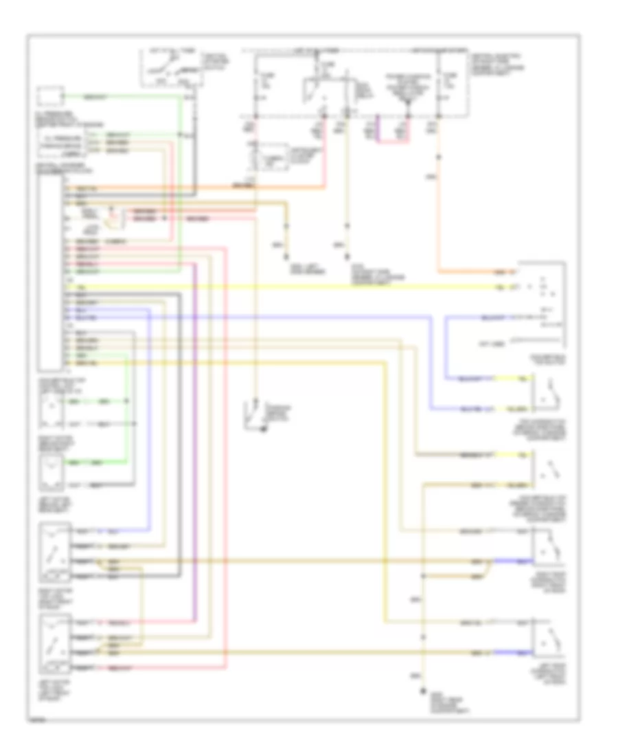
- A/c heater control unit (center of i/p)
- B12
- C 1995 vftc
- Central electric
- Defrost flap
- Engine compartment fuses
- Footwell flap
- Fresh air flap
- Fuse 15a
- Fuse 25a
- Fuse 30a
- Fuse 7.5a
- Fuse 75a
- G105
- H25
- Hot at all times
- Hot in run
- Hot in run or start
- Interior lights system
- K15
- Mfi + di control unit (below left seat)
- Red
- Speedometer (speed input)
- Temperature mixing valve left
- Temperature mixing valve right
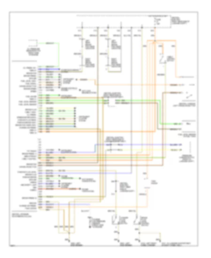
Air Conditioning Wiring Diagrams (2 of 2) for Porsche 911 Carrera 4 1995
List of elements for Air Conditioning Wiring Diagrams (2 of 2) for Porsche 911 Carrera 4 1995:
- (battery,on left side of luggage compart- ment)
- (on right side member in luggage compartment)
- A/c compressor
- A/c compressor relay (carrier plate in engine compartment)
- Blower final stage (center rear of luggage compartment)
- Blower relay
- Blower resistor (left side of engine compartment)
- C 1995 vftc
- C42
- Central electric (on right side member,in luggage compart- ment)
- Condenser blower
- Condenser blower relay (central electric)
- Condenser blower resistor (front left wheel housing)
- Engine compartment blower
- Evaporator freezing protection sensor
- Fuse 30a
- G104
- G105
- G105 (on right side member in luggage compartment)
- G404 (left rear of engine compart- ment)
- H24
- High/low pressure
- Hot at all times
- Left blower motor
- Left mixing chamber sensor
- Mean effective pressure
- Ntc engine compartment blower sensor
- Ntc oil temperature sensor
- Oil cooler blower
- Oil cooler blower resistor (front right wheel housing)
- Oil cooler relay (central electric)
- Power distribution (term x relay)
- Rear fog light/back- up light relay
- Red
- Right blower motor
- Right mixing chamber sensor
- Three-point switch (center rear of luggage compartment)
- Trans- mission control system
Air Conditioning Wiring Diagrams, Early Production (1 of 2) for Porsche 911 Carrera 4 1995
List of elements for Air Conditioning Wiring Diagrams, Early Production (1 of 2) for Porsche 911 Carrera 4 1995:
- (on right side member in lug- gage compt)
- (passenger's footwell)
- A/c heater control unit (center of i/p)
- B12
- C 1995 vftc
- Central electric (on right side member,in luggage compart- ment)
- Defrost flap
- Engine compartment fuses
- Exterior lights system
- Footwell flap
- Fresh air flap
- Fuse 15a
- Fuse 25a
- Fuse 30a
- Fuse 7.5a
- Fuse 75a
- G105
- H25
- Hot at all times
- Hot in run
- Hot in run or start
- Interior lights system
- K15
- Mfi + di control unit (below left seat)
- Red
- Speedometer (speed input)
- Temperature mixing valve left
- Temperature mixing valve right
Air Conditioning Wiring Diagrams, Early Production (2 of 2) for Porsche 911 Carrera 4 1995
List of elements for Air Conditioning Wiring Diagrams, Early Production (2 of 2) for Porsche 911 Carrera 4 1995:
- (in luggage compt, on left wheel well)
- (on right side member in luggage compartment)
- A/c compressor
- A/c compressor relay (carrier plate in engine compartment)
- Blower final stage (center rear of luggage compartment)
- Blower relay
- Blower resistor (left side of engine compartment)
- C 1995 vftc
- C42
- Central electric (on right side member,in luggage compart- ment)
- Condenser blower
- Condenser blower relay (central electric)
- Condenser blower resistor (front left wheel housing)
- Engine compartment blower
- Evaporator freezing protection sensor
- Fuse 30a
- G100
- G105
- G105 (on right side member in luggage compartment)
- G133 (on crankshaft)
- G404 (left rear of engine compart- ment)
- H24
- High/low pressure
- Hot at all times
- Left blower motor
- Left mixing chamber sensor
- Mean effective pressure
- Ntc heater fan
- Ntc oil temperature sensor
- Oil cooler blower
- Oil cooler blower resistor (front right wheel housing)
- Oil cooler relay (central electric)
- Power distribution (term x relay)
- Rear fog light/back- up light relay
- Red
- Right blower motor
- Right mixing chamber sensor
- Three level pressure switch (center rear of luggage compartment)
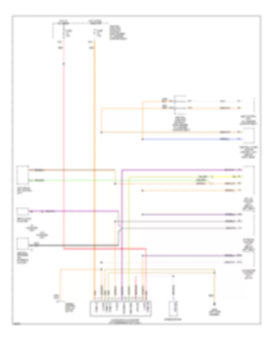
Air Conditioning Wiring Diagrams, Late Production (1 of 2) for Porsche 911 Carrera 4 1995
List of elements for Air Conditioning Wiring Diagrams, Late Production (1 of 2) for Porsche 911 Carrera 4 1995:
- (on right side member in lug- gage compt)
- (passenger's footwell)
- A/c heater control unit (center of i/p)
- B12
- C 1995 vftc
- Central electric (on right side member,in luggage compart- ment)
- Defrost flap
- Engine compartment fuses
- Exterior lights system
- Footwell flap
- Fresh air flap
- Fuse 15a
- Fuse 25a
- Fuse 30a
- Fuse 7.5a
- Fuse 75a
- G105
- H25
- Hot at all times
- Hot in run
- Hot in run or start
- Interior lights system
- K15
- Mfi + di control unit (below left seat)
- Outside temperature sensor (front left bumper)
- Rear shift flap
- Red
- Shift valve circulating air flap (on engine)
- Speedometer (speed input)
- Starter
- Temperature mixing valve left
- Temperature mixing valve right
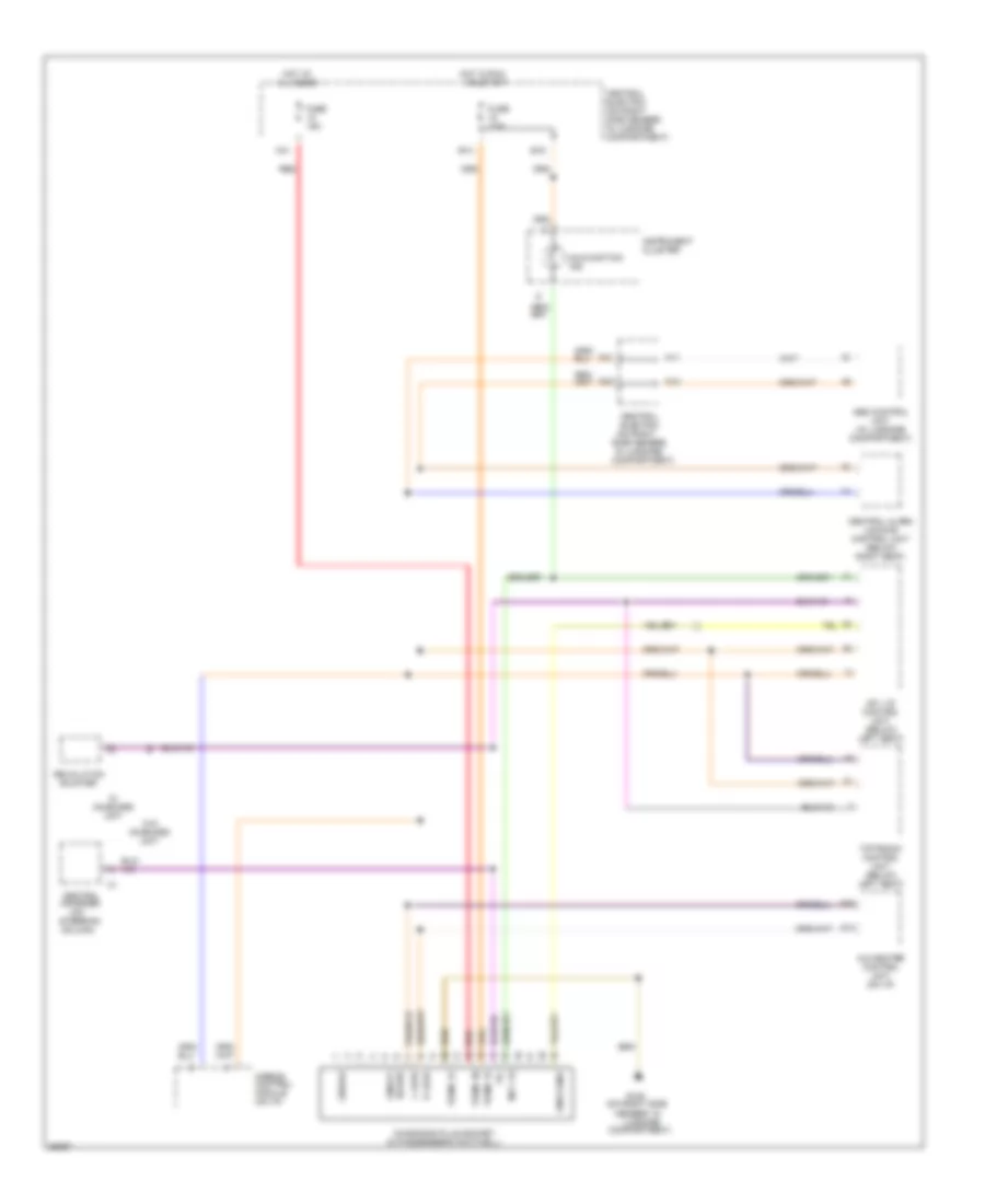
Air Conditioning Wiring Diagrams, Late Production (2 of 2) for Porsche 911 Carrera 4 1995
List of elements for Air Conditioning Wiring Diagrams, Late Production (2 of 2) for Porsche 911 Carrera 4 1995:
- (in luggage compt, on left wheel well)
- (on right side member in luggage compartment)
- A/c compressor
- A/c compressor relay (carrier plate in engine compartment)
- Blower final stage (center rear of luggage compartment)
- Blower relay
- Blower resistor (left side of engine compartment)
- C42
- Central electric (on right side member,in luggage compart- ment)
- Condenser blower
- Condenser blower relay (central electric)
- Condenser blower resistor (front left wheel housing)
- Engine compartment blower
- Evaporator freezing protection sensor
- Fuse 15a
- Fuse 30a
- G100
- G105
- G105 (on right side member in luggage compartment)
- G133 (on camshaft casing cylinder 3)
- G404 (left rear of engine compart- ment)
- H23
- H24
- High/low pressure
- Hot at all times
- Hot in run
- Left blower motor
- Left mixing chamber sensor
- Mean effective pressure
- Ntc heater fan
- Ntc oil temperature sensor
- Oil cooler blower
- Oil cooler blower resistor (front right wheel housing)
- Oil cooler relay (central electric)
- Or start
- Power distribution (term x relay)
- Rear fog light/back- up light relay
- Red
- Right blower motor
- Right mixing chamber sensor
- Three level pressure switch (center rear of luggage compartment)
ANTI-LOCK BRAKES
Anti-lock Brake Wiring Diagrams, Early Production (1 of 2) for Porsche 911 Carrera 4 1995
List of elements for Anti-lock Brake Wiring Diagrams, Early Production (1 of 2) for Porsche 911 Carrera 4 1995:
- (m224)
- (m339)
- (not
- (not m224)
- Abd info
- Abd safety lamp
- Abd sfty lmp
- Abs control unit (right front of luggage compt)
- Abs safety lamp
- Abs sfty lmp
- Actuatn vlve rly
- B15
- B24
- B45
- Brake fluid
- Brke press
- Brke press a
- Brke press b
- Central electric (on right side member, in luggage compartment)
- Central informer (left side of dash)
- Conn 1
- Conn 2
- D42
- Diagnosis "k"
- Diagnosis "l"
- E12
- E15
- Eng rly ctrl
- Engine controls system
- Engine relay
- Fuse 15a
- Fuse 7.5a
- G101 (luggage compartment, on right wheelwell)
- H12
- H23
- Hot in acc or run
- Hot in run or start
- Intake valve
- J42
- K15
- Left front wheel speed sensor
- Left rear wheel speed sensor
- Lft frt exh valve
- Lft frt inl valve
- Lft frt sensor
- Lft rr eso
- Lft rr exh valve
- Lft rr inl valve
- Lft rr sensor
- M15
- Module ground
- Motor ctrl
- N45
- Nca
- Red
- Right front wheel speed sensor
- Right rear wheel speed sensor
- Rr intake valve
- Rt frt eso
- Rt frt exh valve
- Rt frt inl valve
- Rt frt sensor
- Rt rr exh valve
- Rt rr sensor
- Sensor ground
- Shift valve
- Speed in
- Starting/ charging system
- Stoplight sw
- Stoplight switch (under floor pan, forward of left front seat)
- Term 61
- Throttle vlv info
- Transmissions system (tiptronic control module)
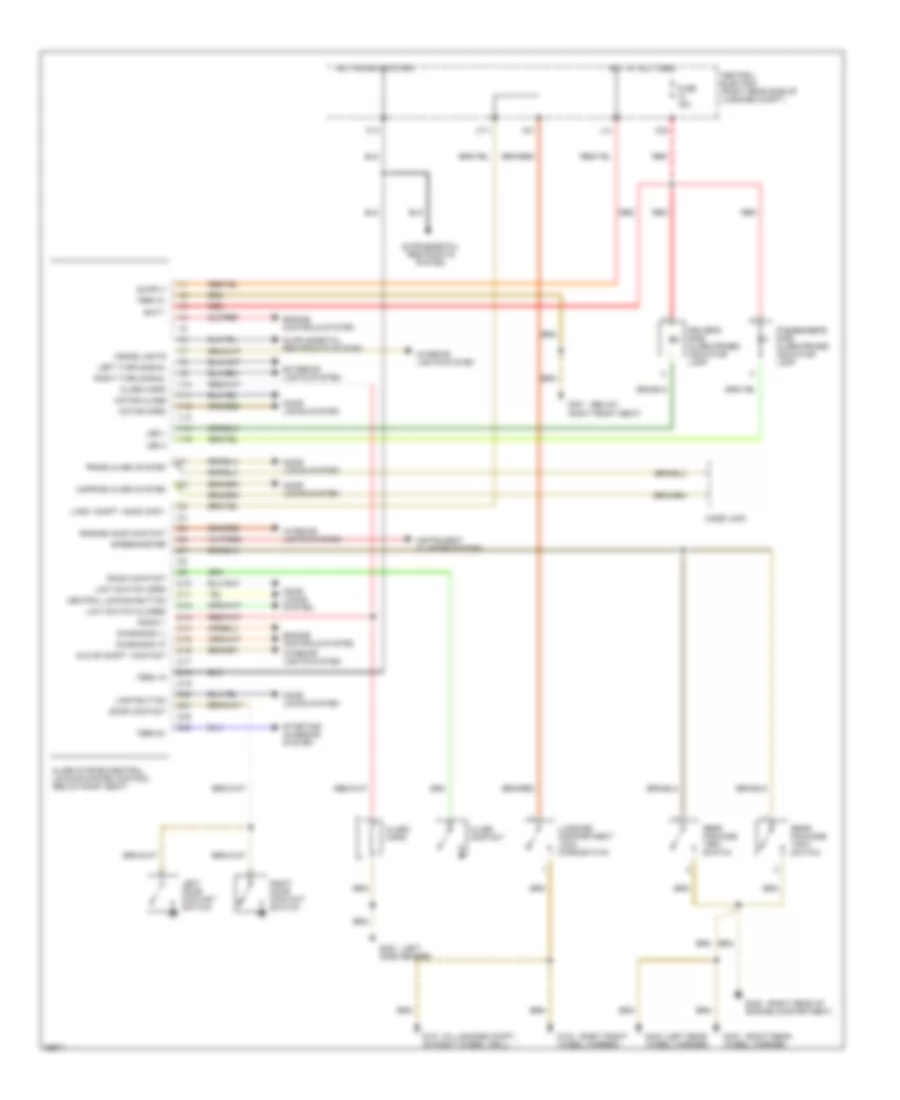
Anti-lock Brake Wiring Diagrams, Early Production (2 of 2) for Porsche 911 Carrera 4 1995
List of elements for Anti-lock Brake Wiring Diagrams, Early Production (2 of 2) for Porsche 911 Carrera 4 1995:
- Abd info indic
- Abd safety indic
- Abs hydraulic actuator unit (w/o traction control: m224) (left side of luggage compt)
- Abs safety indic
- Abs/abd hydraulic actuator unit (w/ traction control: m224) (left side of luggage compt)
- Battery
- Booster pump motor (front center of luggage compt)
- Booster pump relay (right side of luggage compt)
- Brake pressure indic
- Braking circuit indic
- Engine relay
- G101 (luggage compartment, on right wheelwell)
- Instrument cluster
- Pressure warning switch (front center of luggage compt)
- Red
- Valve relay
Anti-lock Brake Wiring Diagrams, Late Production (1 of 2) for Porsche 911 Carrera 4 1995
List of elements for Anti-lock Brake Wiring Diagrams, Late Production (1 of 2) for Porsche 911 Carrera 4 1995:
- (m224)
- (m339)
- (not m224)
- (not m339)
- Abd info
- Abd safety lamp
- Abd sfty lmp
- Abs control unit (right front of luggage compt)
- Abs safety lamp
- Abs sfty lmp
- Actuatn vlve rly
- B15
- B24
- B45
- Brake fluid
- Brake pressure switch (m003) (rs only) (on some models this switch is replaced by a jumper connector)
- Brke press
- Brke press a
- Brke press b
- Central electric (on right side member, in luggage compartment)
- Central informer (left side of dash)
- Conn 1
- Conn 2
- D42
- Diagnosis "k"
- Diagnosis "l"
- E12
- E15
- Eng rly ctrl
- Engine controls system
- Engine relay
- Fuse 15a
- Fuse 7.5a
- G101 (luggage compartment, on right wheelwell)
- H12
- H23
- Hot in acc or run
- Hot in run or start
- Intake valve
- J42
- K15
- Left front wheel speed sensor
- Left rear wheel speed sensor
- Lft frt exh valve
- Lft frt inl valve
- Lft frt sensor
- Lft rr eso
- Lft rr exh valve
- Lft rr inl valve
- Lft rr sensor
- M15
- Module ground
- Motor ctrl
- N45
- Nca
- Other
- Red
- Right front wheel speed sensor
- Right rear wheel speed sensor
- Rr intake valve
- Rt frt eso
- Rt frt exh valve
- Rt frt inl valve
- Rt frt sensor
- Rt rr exh valve
- Rt rr sensor
- Sensor ground
- Shift valve
- Speed in
- Starting/ charging system
- Stoplight sw
- Stoplight switch (under floor pan, forward of left front seat)
- Term 61
- Throttle vlv info
- Transmissions system (tiptronic control module)
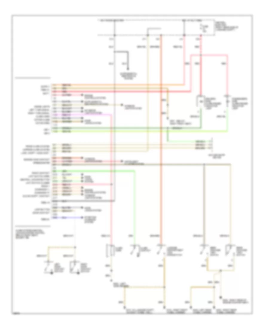
Anti-lock Brake Wiring Diagrams, Late Production (2 of 2) for Porsche 911 Carrera 4 1995
List of elements for Anti-lock Brake Wiring Diagrams, Late Production (2 of 2) for Porsche 911 Carrera 4 1995:
- Abd info indic
- Abd safety indic
- Abs hydraulic actuator unit (w/o traction control: m224) (left side of luggage compt)
- Abs safety indic
- Abs/abd hydraulic actuator unit (w/ traction control: m224) (left side of luggage compt)
- Battery
- Battery main switch
- Booster pump motor (front center of luggage compt)
- Booster pump relay (right side of luggage compt)
- Brake pressure indic
- Braking circuit indic
- Engine relay
- G101 (luggage compartment, on right wheelwell)
- Instrument cluster
- Other
- Pressure warning switch for brake booster pump (front center of luggage compt)
- Red
- Valve relay
ANTI-THEFT
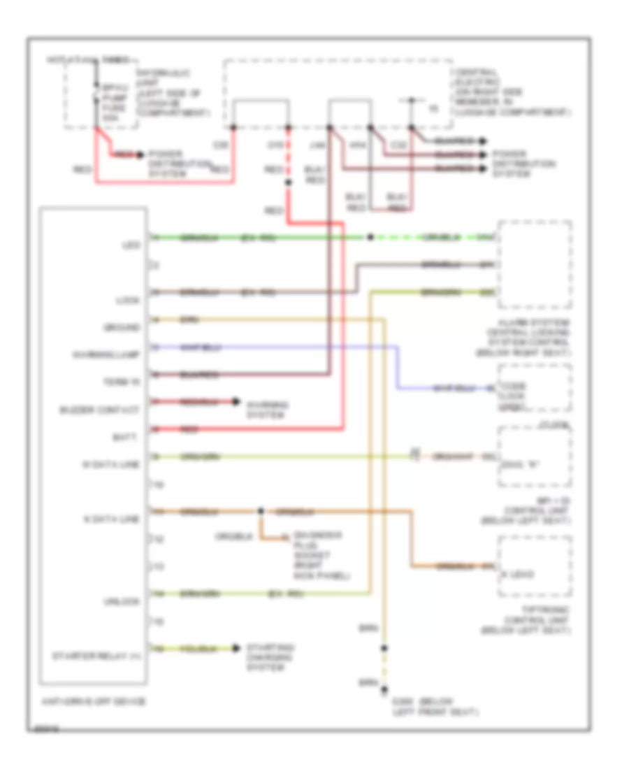
Anti-Drive-Off Wiring Diagram, Late Production for Porsche 911 Carrera 4 1995
List of elements for Anti-Drive-Off Wiring Diagram, Late Production for Porsche 911 Carrera 4 1995:
- (below
- (ex. rs)
- 1/14
- 2/1
- 2/2
- Alarm system/ central locking system control (below right seat)
- Anti-drive-off device
- Batt.
- Bpau pump fuse 60a
- Buzzer contact
- C32
- C35
- Central electric (on right side memeber, in luggage compartment)
- Clock
- Code
- Diag. "k"
- Diagnosis
- G300 left front seat)
- Ground
- H14
- Hot at all times
- Hydraulic unit (left side of luggage compartment)
- J44
- K data line
- K lead
- Led
- Lock
- Lock indic.
- Mfi + di control unit (below left seat)
- O15
- Plug socket (right kick panel)
- Power distribution system
- Red
- Starter relay (+)
- Starting/ charging system
- Term 15
- Tiptronic control unit (below left seat)
- Unlock
- W data line
- Warning lamp
- Warning system
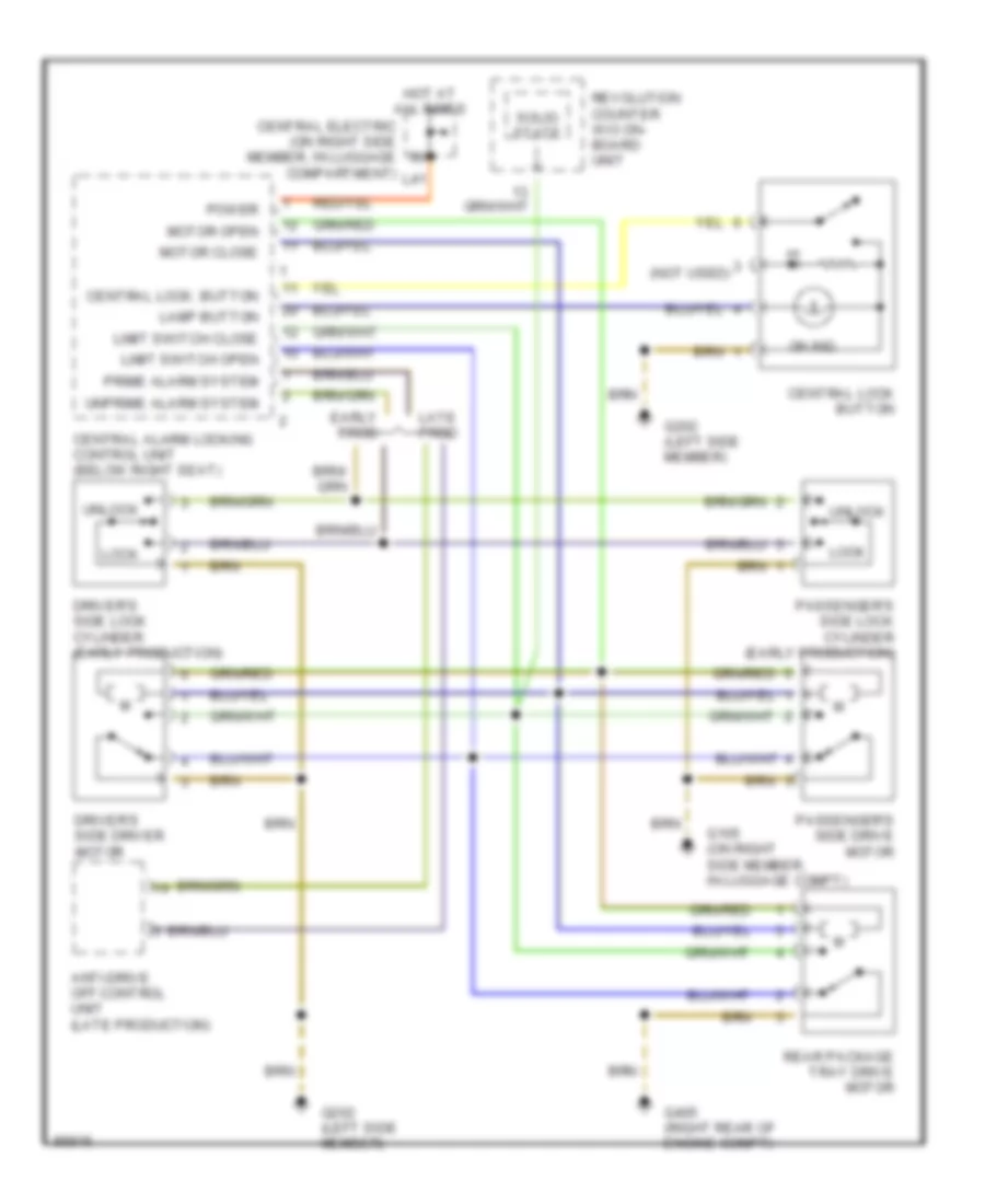
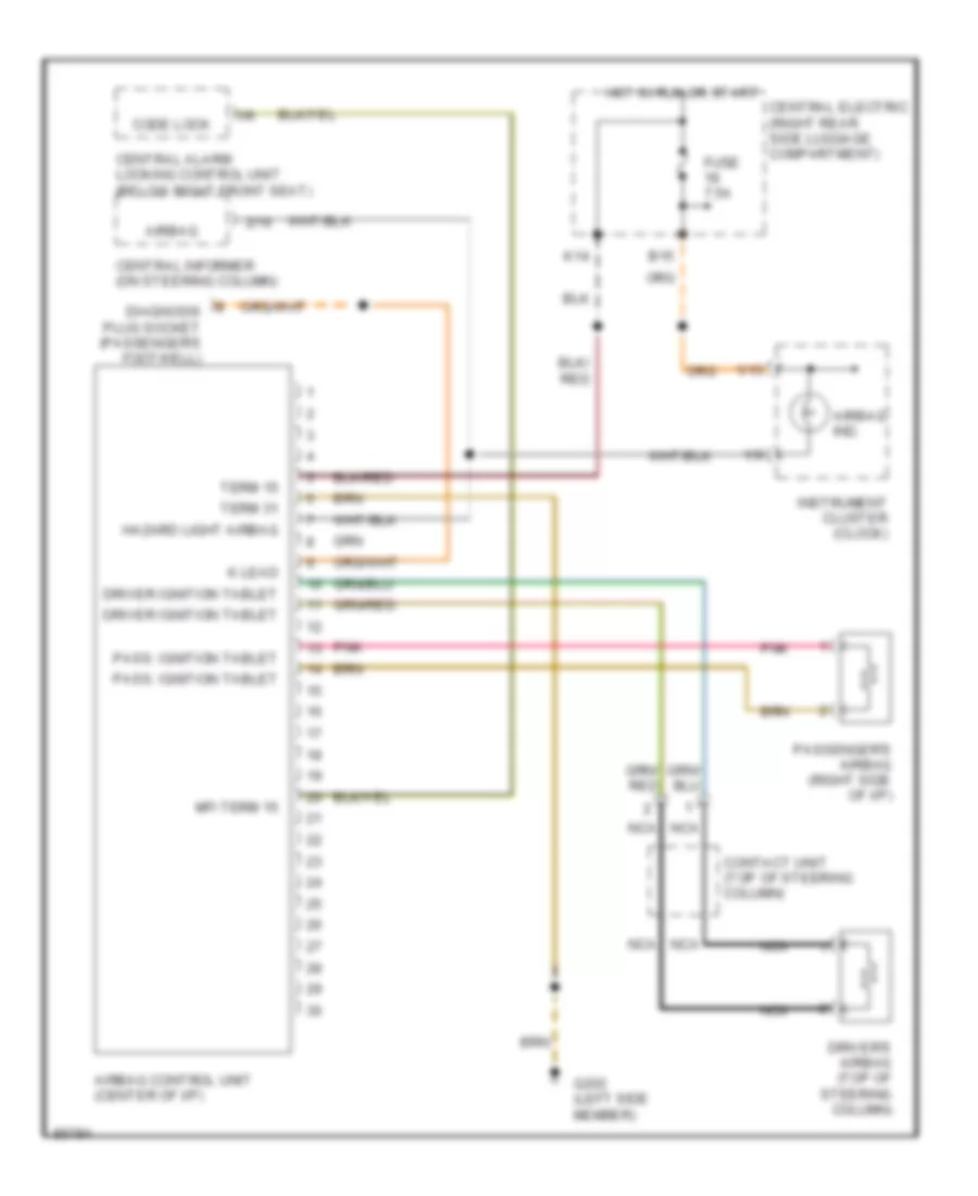
Anti-theft Wiring Diagram, Early Production for Porsche 911 Carrera 4 1995
List of elements for Anti-theft Wiring Diagram, Early Production for Porsche 911 Carrera 4 1995:
- (below
- (in luggage compt.,
- (left
- (left rear
- (right front
- (right rear
- (right rear of
- 1/1
- 1/10
- 1/11
- 1/12
- 1/13
- 1/14
- 1/15
- 1/2
- 1/3
- 1/4
- 1/5
- 1/6
- 1/7
- 1/8
- 1/9
- 2/1
- 2/10
- 2/11
- 2/12
- 2/13
- 2/14
- 2/15
- 2/16
- 2/17
- 2/18
- 2/19
- 2/2
- 2/20
- 2/21
- 2/22
- 2/23
- 2/3
- 2/4
- 2/5
- 2/6
- 2/7
- 2/8
- 2/9
- Alarm contact
- Alarm horn
- Alarm system/central locking system control (below right seat)
- Batt.
- Central electric (right rear side of luggage compt.)
- Central locking button
- Code lock
- Diagnosis "k"
- Diagnosis "l"
- Door contact
- Door locks system
- Driver's side alarm-primed indicator lamp
- Engine controls system
- Engine hood contact
- Exterior lights system
- Fuse 15a
- G101 on right wheel well)
- G103 wheel carrier)
- G202 side member)
- G301 right front seat)
- G402 wheel carrier)
- G403 wheel carrier)
- G405 engine compartment)
- Glove compt. contact
- Hot at all times
- Hot in run or start
- Inside lights
- Instrument cluster system
- Interior lights system
- K14
- K32
- L41
- Lamp button
- Led 1
- Led 2
- Left door contact switch
- Left turn signal
- Limit switch closed
- Limit switch open
- Lugg. compt. hood cont.
- Luggage compartment lock microswitch
- M11
- Motor close
- Motor open
- N41
- Passenger's side alarm-primed indicator lamp
- Prime alarm system
- Radio 1
- Radio contact
- Rear package tray switch
- Red
- Right door contact switch
- Right turn signal
- Speedometer
- Starting/ charging system
- Term 15
- Term 31
- Term 61
- Unprime alarm system
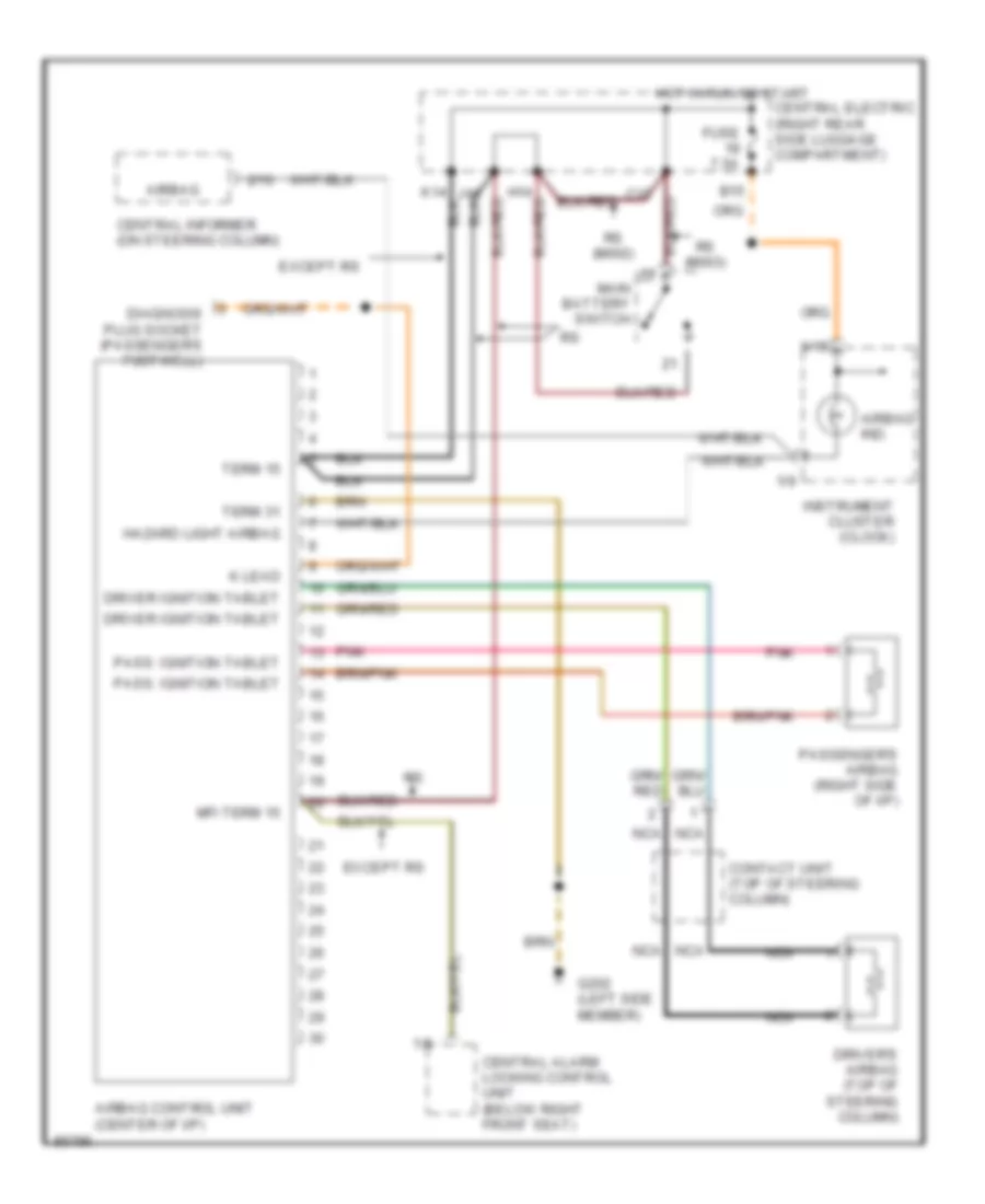
Anti-theft Wiring Diagram, Late Production for Porsche 911 Carrera 4 1995
List of elements for Anti-theft Wiring Diagram, Late Production for Porsche 911 Carrera 4 1995:
- (below
- (in luggage compt.,
- (left
- (left rear
- (right front
- (right rear
- (right rear of
- 1/1
- 1/10
- 1/11
- 1/12
- 1/13
- 1/14
- 1/15
- 1/2
- 1/3
- 1/4
- 1/5
- 1/6
- 1/7
- 1/8
- 1/9
- 2/1
- 2/10
- 2/11
- 2/12
- 2/13
- 2/14
- 2/15
- 2/16
- 2/17
- 2/18
- 2/19
- 2/2
- 2/20
- 2/21
- 2/22
- 2/23
- 2/3
- 2/4
- 2/5
- 2/6
- 2/7
- 2/8
- 2/9
- Alarm contact
- Alarm horn
- Alarm system/central locking system control (below right seat) (except rs)
- Anti-drive-off device
- Batt.
- Central electric (right rear side of luggage compt.)
- Central locking button
- Diagnosis "k"
- Diagnosis "l"
- Door contact
- Door locks system
- Driver's side alarm-primed indicator lamp
- Engine controls system
- Engine hood contact
- Exterior lights system
- Fuse 15a
- G101 on right wheel well)
- G103 wheel carrier)
- G202 side member)
- G301 right front seat)
- G402 wheel carrier)
- G403 wheel carrier)
- G405 engine compartment)
- Glove compt. contact
- Hot at all times
- Hot in run or start
- Inside lights
- Instrument cluster system
- Interior lights system
- K14
- K32
- L41
- Lamp button
- Led 1
- Led 2
- Left door contact switch
- Left turn signal
- Limit switch closed
- Limit switch open
- Lugg. compt. hood cont.
- Luggage compartment lock microswitch
- M11
- Motor close
- Motor open
- N41
- Passenger's side alarm-primed indicator lamp
- Prime alarm system
- Radio 1
- Radio contact
- Rear package tray switch
- Red
- Right door contact switch
- Right turn signal
- Speedometer
- Starting/ charging system
- Term 15
- Term 31
- Term 61
- Unprime alarm system
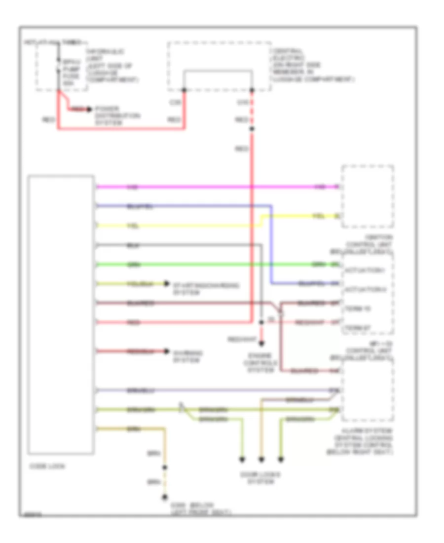
Code Lock Wiring Diagram, Early Production for Porsche 911 Carrera 4 1995
List of elements for Code Lock Wiring Diagram, Early Production for Porsche 911 Carrera 4 1995:
- (below
- 1/4
- 2/1
- 2/2
- Actuation i
- Actuation ii
- Alarm system/ central locking system control (below right seat)
- Bpau pump fuse 60a
- C35
- Central electric (on right side memeber, in luggage compartment)
- Code lock
- Door locks system
- Engine controls system
- G300 left front seat)
- Hot at all times
- Hydraulic unit (left side of luggage compartment)
- Ignition control unit (below left seat)
- Mfi + di control unit (below left seat)
- O15
- Power distribution system
- Red
- Starting/charging system
- Term 15
- Term 87
- Warning system
BODY COMPUTER
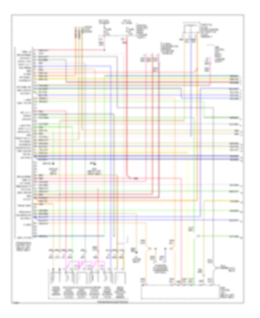
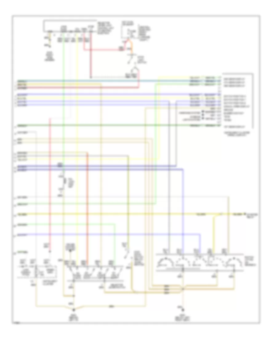
Body Computer Wiring Diagrams, Early Production for Porsche 911 Carrera 4 1995
List of elements for Body Computer Wiring Diagrams, Early Production for Porsche 911 Carrera 4 1995:
- (cabrio)
- (in luggage compartment,
- (left
- (left front
- 1/1
- 1/10
- 1/11
- 1/12
- 1/13
- 1/14
- 1/15
- 1/16
- 1/17
- 1/18
- 1/19
- 1/2
- 1/20
- 1/21
- 1/22
- 1/23
- 1/24
- 1/25
- 1/26
- 1/3
- 1/4
- 1/5
- 1/6
- 1/7
- 1/8
- 1/9
- 2/1
- 2/10
- 2/11
- 2/12
- 2/13
- 2/14
- 2/15
- 2/16
- 2/17
- 2/18
- 2/19
- 2/2
- 2/20
- 2/21
- 2/22
- 2/23
- 2/24
- 2/25
- 2/26
- 2/3
- 2/4
- 2/5
- 2/6
- 2/7
- 2/8
- 2/9
- Abd safety lamp
- Abs
- Active body works system
- Airbag
- Anti-lock brakes system
- B15
- B41
- B42
- B44
- B45
- Brake fluid
- Brake fluid level control switch
- Brake pad
- Brake pad wear indic.
- Brake press.
- Brake press. a
- Brake press. b
- C11
- C12
- C14
- C15
- Cabrio
- Canceling button
- Central electric (right rear side of luggage compartment)
- Central electric (right rear side of luggage compt.)
- Central informer (on steering column)
- Central warning light canceling button
- Engine controls system
- Fuel gauge
- Fuel level indic.
- Fuel level sensor
- Fuel level sensor (in fuel tank)
- Fuel signal
- Fuse 7.5a
- G101 on right wheel well)
- G102 wheel carrier)
- G202 side member)
- Ground
- H12
- Hot in run or start
- Instrument cluster system
- J42
- Left front brake pad wear indicator
- Left rear brake pad wear indicator
- M13
- M14
- M43
- M44
- N13
- O43
- Oil press.
- Oil press. sw.
- Oil pressure sensor/switch (front side of engine)
- Parking brake
- Parking brake indic.
- Power tops system
- Pressure warning switch (front of luggage compt.)
- Right front brake pad wear indicator
- Right rear brake pad wear indicator
- Servotronic
- Speed
- Speedometer signal
- Spoiler
- Starting/charging system
- Tank coding
- Term 15
- Term 31
- Term 61
- Tip tronic
- Toothed belt indic.
- V-belt control
- V-belt control switch
- Washer fluid level switch
- Washing fluid level
- Washing fluid sens.
Body Computer Wiring Diagrams, Late Production for Porsche 911 Carrera 4 1995
List of elements for Body Computer Wiring Diagrams, Late Production for Porsche 911 Carrera 4 1995:
- (cabrio)
- (ex. rs)
- (in luggage compartment,
- (left
- (left front
- (rs)
- 1/1
- 1/10
- 1/11
- 1/12
- 1/13
- 1/14
- 1/15
- 1/16
- 1/17
- 1/18
- 1/19
- 1/2
- 1/20
- 1/21
- 1/22
- 1/23
- 1/24
- 1/25
- 1/26
- 1/3
- 1/4
- 1/5
- 1/6
- 1/7
- 1/8
- 1/9
- 2/1
- 2/10
- 2/11
- 2/12
- 2/13
- 2/14
- 2/15
- 2/16
- 2/17
- 2/18
- 2/19
- 2/2
- 2/20
- 2/21
- 2/22
- 2/23
- 2/24
- 2/25
- 2/26
- 2/3
- 2/4
- 2/5
- 2/6
- 2/7
- 2/8
- 2/9
- Abd safety lamp
- Abs
- Active body works system
- Airbag
- Anti-lock brakes system
- B15
- B41
- B42
- B44
- B45
- Brake fluid
- Brake fluid level control switch
- Brake pad
- Brake pad wear indic.
- Brake press.
- Brake press. a
- Brake press. b
- C11
- C12
- C14
- C15
- Cabrio
- Canceling button
- Central electric (right rear side of luggage compartment)
- Central electric (right rear side of luggage compt.)
- Central informer (on steering column)
- Central warning light canceling button
- Charge air press.
- Charge air pressure sensor (front side of engine)
- Engine controls system
- Engine speed
- Fuel gauge
- Fuel level indic.
- Fuel level sensor
- Fuel level sensor (in fuel tank)
- Fuel signal
- Fuse 7.5a
- G101 on right wheel well)
- G102 wheel carrier)
- G202 side member)
- Ground
- H12
- Hot in run or start
- Instrument cluster system
- J42
- Left front brake pad wear indicator
- Left rear brake pad wear indicator
- M13
- M14
- M43
- M44
- N13
- O43
- Oil press.
- Oil press. sw.
- Oil pressure sensor/switch (front side of engine)
- Parking brake
- Parking brake indic.
- Power tops system
- Pressure warning switch (front of luggage compt.)
- Right front brake pad wear indicator
- Right rear brake pad wear indicator
- Servotronic
- Speed
- Speedometer signal
- Spoiler
- Starting/charging system
- Tank coding
- Term 15
- Term 31
- Term 61
- Tip tronic
- V-belt control
- V-belt control switch
- V-belt indic.
- Washer fluid level switch
- Washing fluid level
- Washing fluid sens.
COMPUTER DATA LINES
Diagnosis Plug Socket Wiring Diagram, Early Production for Porsche 911 Carrera 4 1995
List of elements for Diagnosis Plug Socket Wiring Diagram, Early Production for Porsche 911 Carrera 4 1995:
- (in passenger's footwell)
- (on
- (on right side
- A/c-heater control unit (on i/p)
- Abs control unit (in luggage compartment)
- Airbag
- Airbag control module (on i/p)
- All times
- B14
- B15
- Central alarm locking control unit (below right seat)
- Central electric (on right
- Central electric (on right side member, in luggage compartment)
- Central informer
- Compartment)
- D41
- D42
- Diagnosis plug socket
- Fuse 15a
- Fuse 7.5a
- G105
- G14
- G32
- Hot at
- Hot in run
- Instrument cluster
- K lead
- K31
- Knocking
- L lead
- Luggage
- Malfunction ind.
- Member, in
- Mfi + di
- Mfi + di control unit (below left seat)
- N11
- N12
- On/off board
- Or start
- Red
- Revolution counter
- Side member, in luggage compartment)
- Steering column)
- Td-
- Term. 15
- Term. 30
- Term. 31
- Tiptronic control unit (below left seat)
- W/ on-board unit
- W/o on-board unit
Diagnosis Plug Socket Wiring Diagram, Late Production for Porsche 911 Carrera 4 1995
List of elements for Diagnosis Plug Socket Wiring Diagram, Late Production for Porsche 911 Carrera 4 1995:
- (in passenger's footwell)
- A/c-heater control unit (on i/p)
- Abs control unit (in luggage compartment)
- Airbag control module (on i/p)
- All times
- Anti drive off control unit
- B14
- Central alarm locking control unit (below right seat)
- Central electric (on right
- Central electric (on right side member, in luggage compartment)
- Central informer (on steering column)
- D41
- D42
- Diagnosis plug socket
- Fuse 15a
- Fuse 7.5a
- G14
- G202 (left side member)
- G32
- Hot at
- Hot in run
- K lead
- K32
- Knocking
- L lead
- Mfi + di control unit (below left seat)
- N11
- N12
- Or start
- Red
- Revolution counter
- Side member, in luggage compartment)
- Spd sig
- Speedometer
- Term. 15
- Term. 30
- Term. 31
- Tiptronic control unit (below left seat)
- Tn signal
- W/ on-board unit
- W/o on-board unit
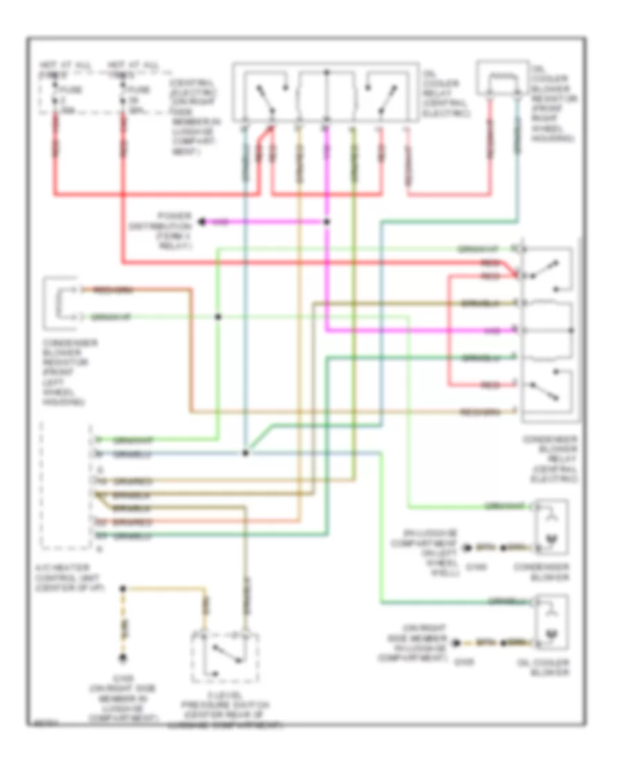
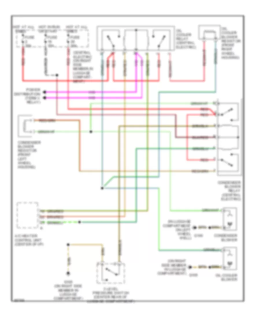
COOLING FAN
Cooling Fan Wiring Diagram, Early Production for Porsche 911 Carrera 4 1995
List of elements for Cooling Fan Wiring Diagram, Early Production for Porsche 911 Carrera 4 1995:
- (in luggage compartment on left wheel well)
- (on right side member in luggage compartment)
- 3 level pressure switch (center rear of luggage compartment)
- A/c heater control unit (center of i/p)
- C42
- Central electric (on right side member,in luggage compart- ment)
- Condenser blower
- Condenser blower relay (central electric)
- Condenser blower resistor (front left wheel housing)
- Fuse 30a
- G100
- G105
- G105 (on right side member in luggage compartment)
- H24
- Hot at all times
- Oil cooler blower
- Oil cooler blower resistor (front right wheel housing)
- Oil cooler relay (central electric)
- Power distribution (term x relay)
- Red
Cooling Fan Wiring Diagram, Late Production for Porsche 911 Carrera 4 1995
List of elements for Cooling Fan Wiring Diagram, Late Production for Porsche 911 Carrera 4 1995:
- (in luggage compartment on left wheel well)
- (on right side member in luggage compartment)
- 3 level pressure switch (center rear of luggage compartment)
- A/c heater control unit (center of i/p)
- C42
- Central electric (on right side member,in luggage compart- ment)
- Condenser blower
- Condenser blower relay (central electric)
- Condenser blower resistor (front left wheel housing)
- Fuse 15a
- Fuse 30a
- G100
- G105
- G105 (on right side member in luggage compartment)
- H23
- H24
- Hot at all
- Hot at all times
- Hot in run or start
- Oil cooler blower
- Oil cooler blower resistor (front right wheel housing)
- Oil cooler relay (central electric)
- Power distribution (term x relay)
- Red
- Times
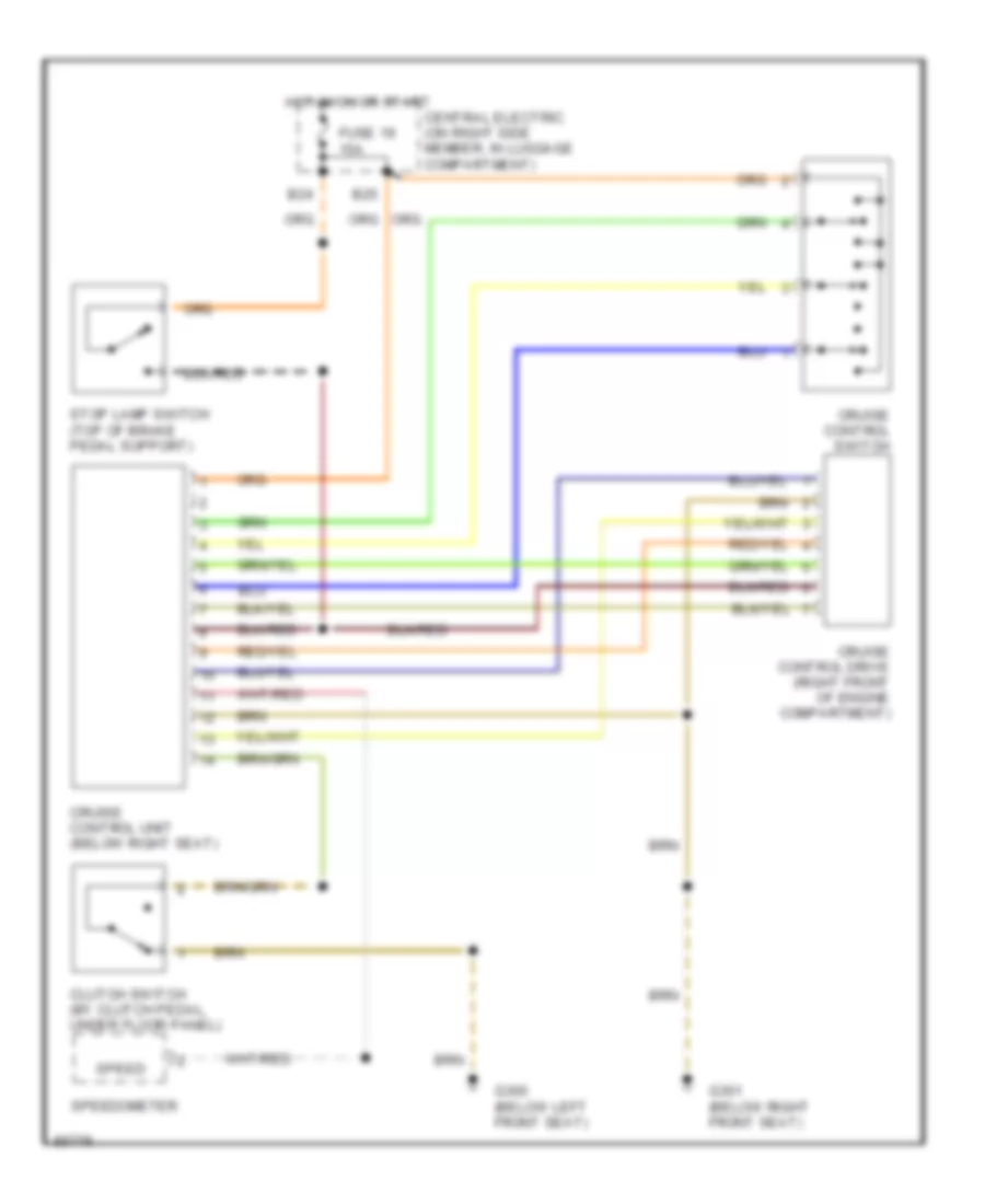
CRUISE CONTROL
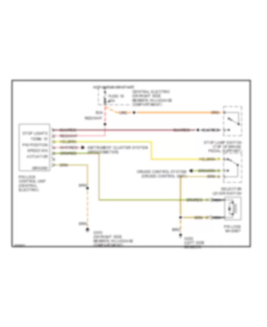
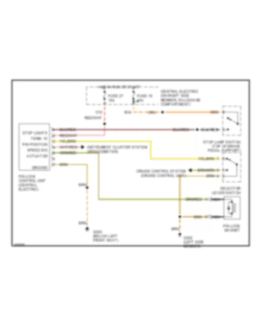
Cruise Control Wiring Diagram for Porsche 911 Carrera 4 1995
List of elements for Cruise Control Wiring Diagram for Porsche 911 Carrera 4 1995:
- B24
- B25
- Central electric (on right side member, in luggage compartment)
- Clutch switch (by clutch pedal, under floor panel)
- Cruise control drive (right front of engine compartment)
- Cruise control switch
- Cruise control unit (below right seat)
- Fuse 19 15a
- G300 (below left front seat)
- G301 (below right front seat)
- Hot in on or start
- Speed
- Speedometer
- Stop lamp switch (top of brake pedal support)
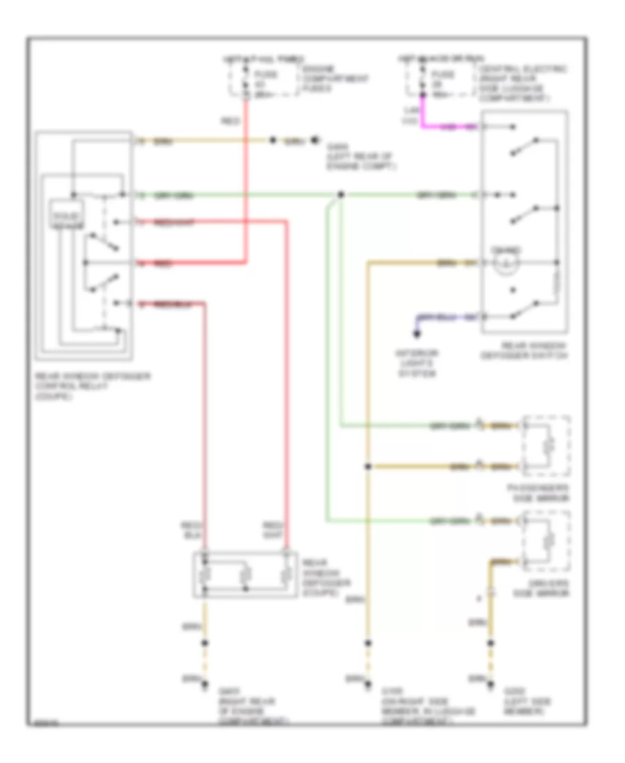
DEFOGGERS
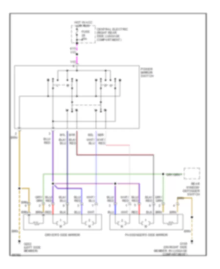
Defogger Wiring Diagram, Early Production for Porsche 911 Carrera 4 1995
List of elements for Defogger Wiring Diagram, Early Production for Porsche 911 Carrera 4 1995:
- Central electric (right rear side luggage compartment)
- Driver's side mirror
- Engine compartment fuses
- Fuse 15a
- Fuse 25a
- G105 (on right side member, in luggage compartment)
- G202 (left side member)
- G404 (left rear of engine compt)
- G405 (right rear of engine compartment)
- Hot at all times
- Hot in acc or run
- Interior lights system
- L44
- On ind.
- Passenger's side mirror
- Rear window defogger (coupe)
- Rear window defogger control relay (coupe)
- Rear window defogger switch
- Red
- Solid state
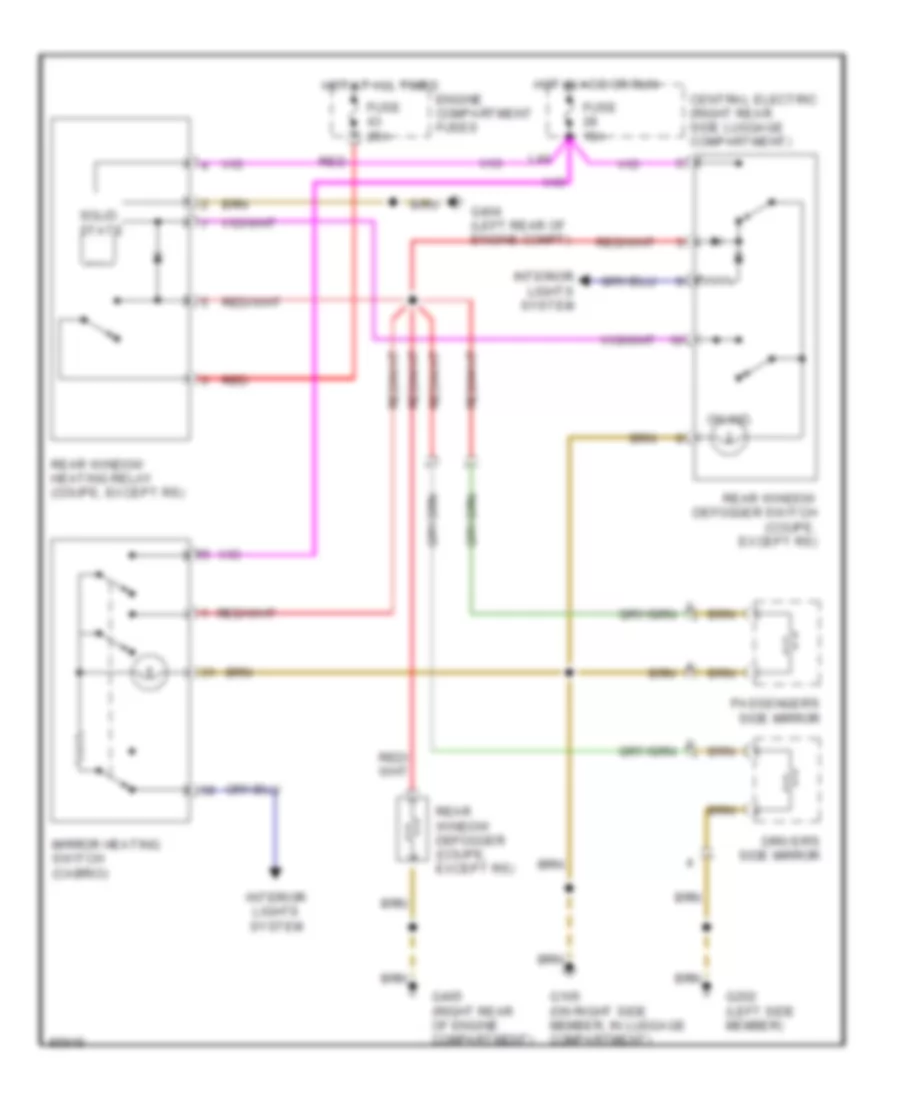
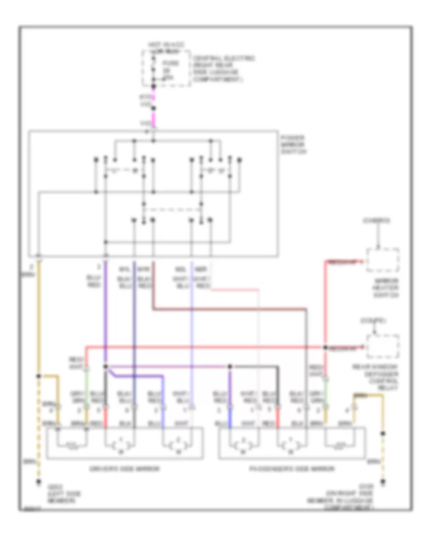
Defogger Wiring Diagram, Late Production for Porsche 911 Carrera 4 1995
List of elements for Defogger Wiring Diagram, Late Production for Porsche 911 Carrera 4 1995:
- Central electric (right rear side luggage compartment)
- Driver's side mirror
- Engine compartment fuses
- Fuse 15a
- Fuse 25a
- G105 (on right side member, in luggage compartment)
- G202 (left side member)
- G404 (left rear of engine compt)
- G405 (right rear of engine compartment)
- Hot at all times
- Hot in acc or run
- Interior lights system
- L44
- Mirror heating switch (cabrio)
- On ind.
- Passenger's side mirror
- Rear window defogger (coupe, except rs)
- Rear window defogger switch (coupe, except rs)
- Rear window heating relay (coupe, except rs)
- Red
- Solid state
ENGINE PERFORMANCE
3.6L
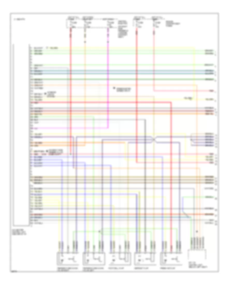
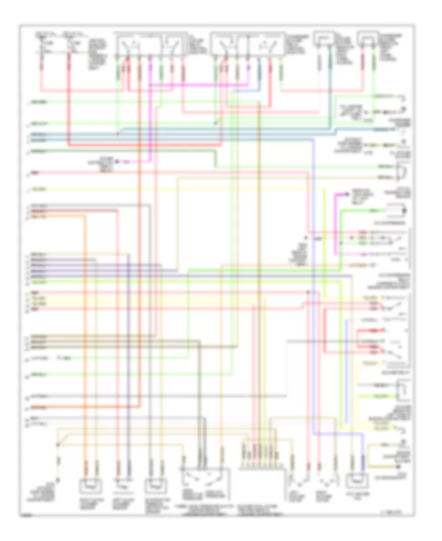
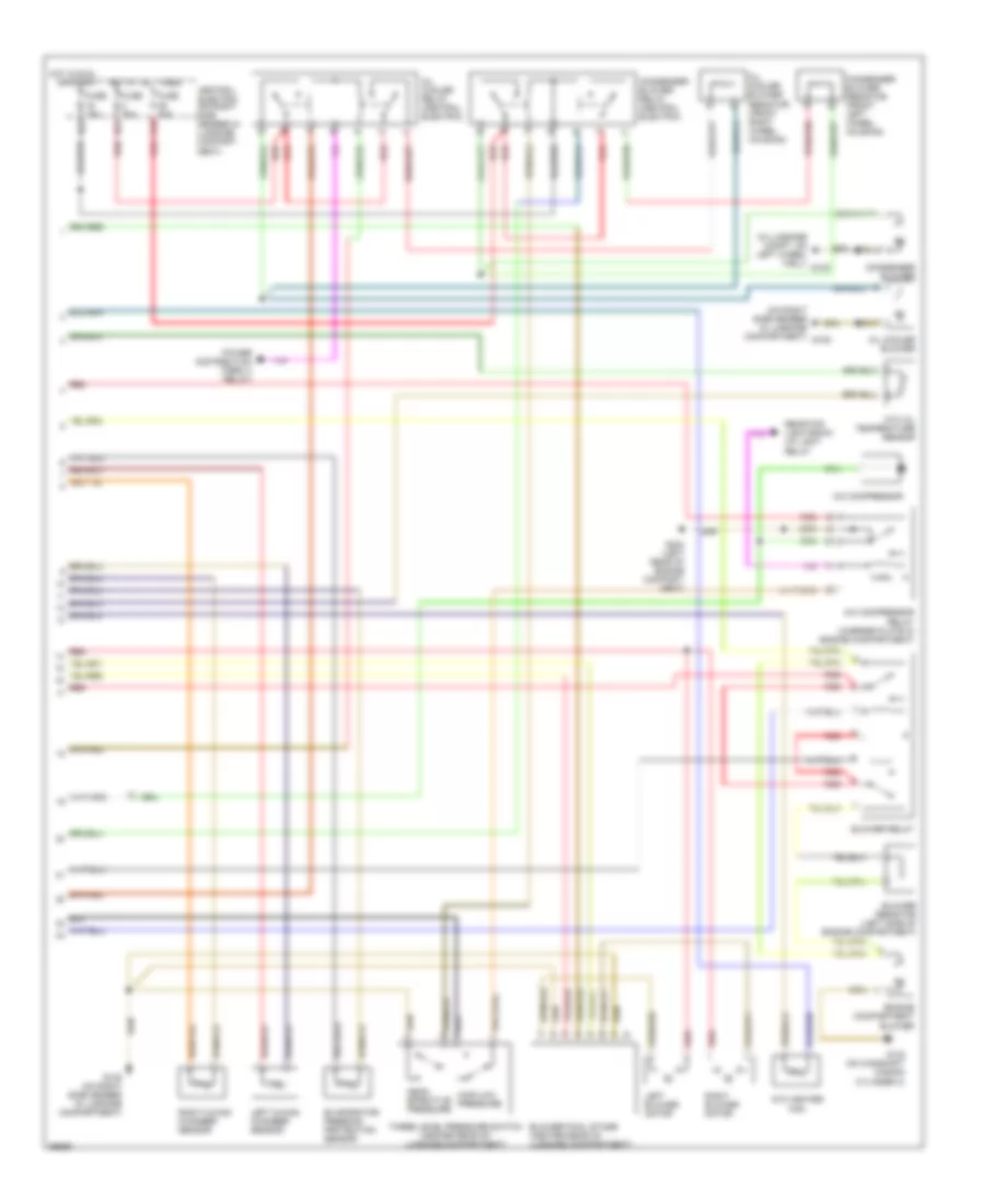
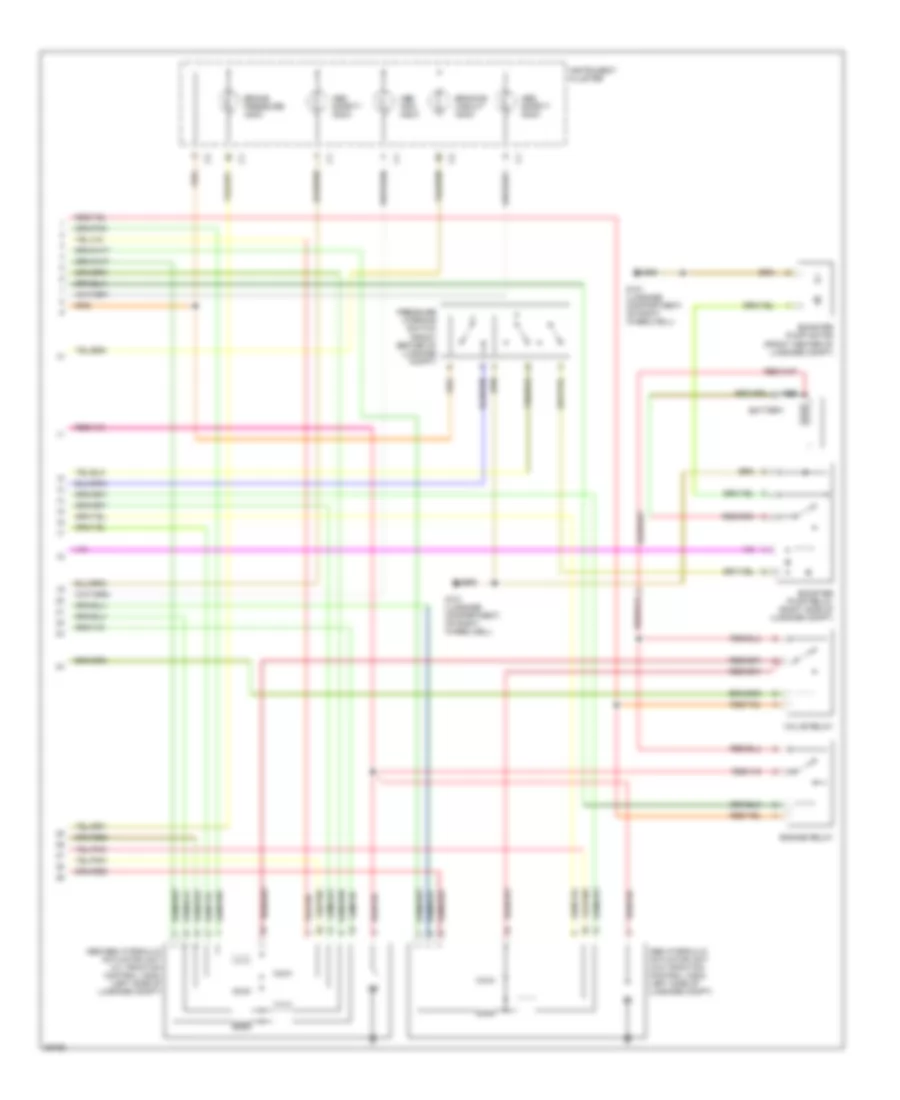
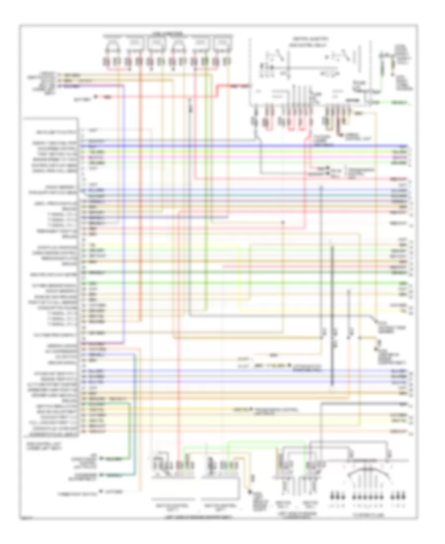
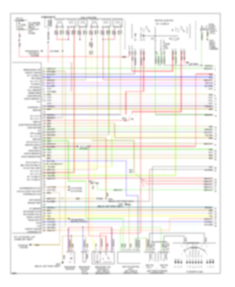
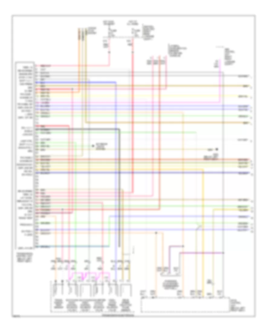
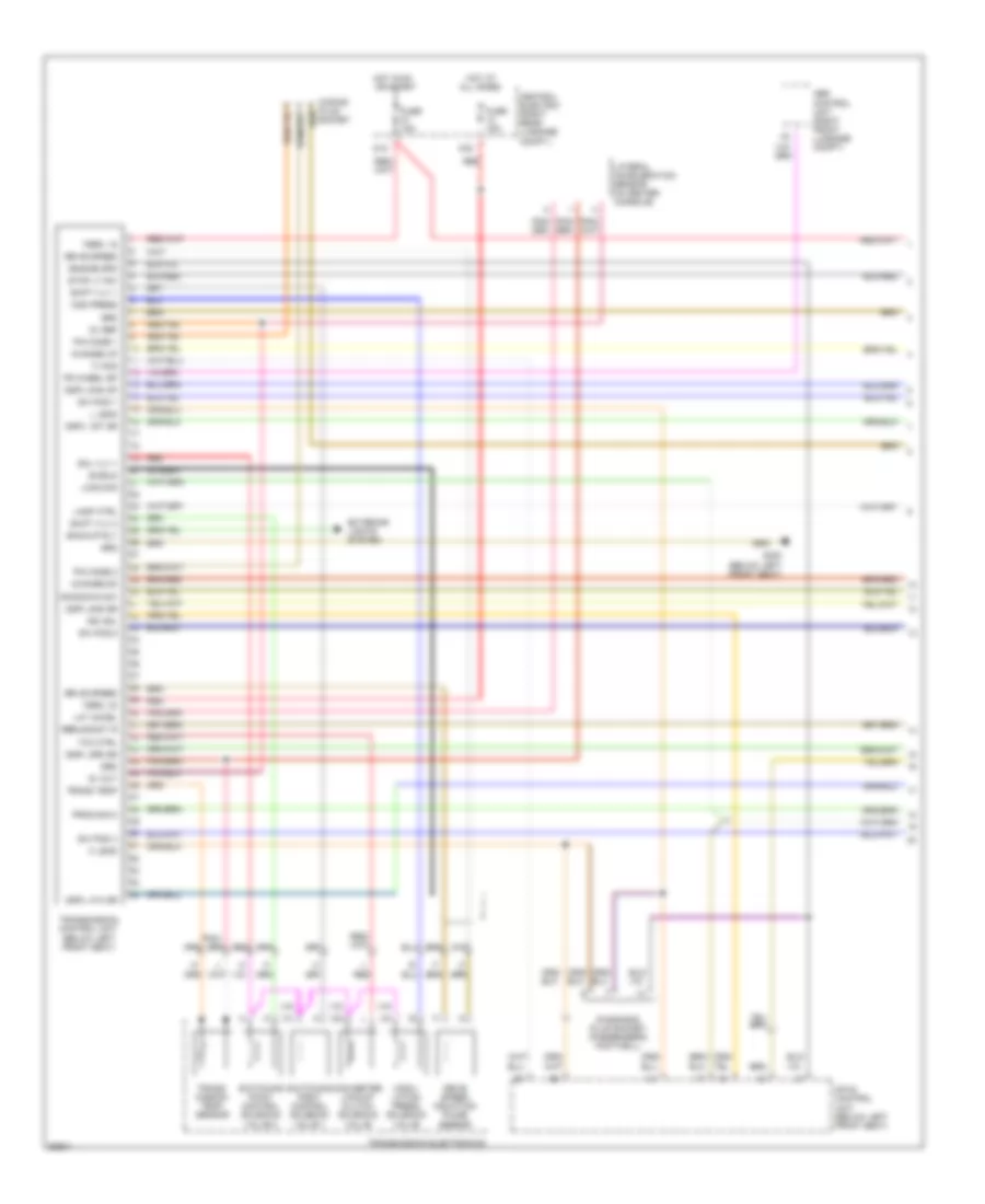
3.6L, Engine Performance Wiring Diagrams (1 of 2) for Porsche 911 Carrera 4 1995
List of elements for 3.6L, Engine Performance Wiring Diagrams (1 of 2) for Porsche 911 Carrera 4 1995:
- (center of engine compartment)
- (left side of engine compartment)
- (rs only)
- (under left seat)
- (w/ a/t)
- 85b
- 87b
- A/c compressor
- A/c switch
- Air conditioning control unit pin k12
- Airbag control unit
- Altitude potentiometer
- Battery
- C43
- Central electric
- Check engine control
- Coding plug, char map
- Condenser blower relay
- Consumption gauge
- Diag plug, knocking
- Diagnostic plug, lead k
- Distributor
- Dme control relay
- Dme control unit
- Dme rly gnd (fuel pmp)
- E21
- E22
- E24
- E25
- E31
- E32
- E34
- E35
- E42
- E44
- Eng ign adjustment
- Engine speed to tach
- Engine temp ntc 2
- F12
- F14
- F23
- F25
- Fuel injectors
- Fuel pump (right safety wall)
- Full load sig-throt vlv
- Fuse 15a
- Fuse 7.5a
- G100 (right wheel housing)
- G123 (on right side member)
- G25
- G402 (left rear of engine compt)
- Gnd for air flow meter
- Ground
- Ground signal
- Heat/a/c regulation
- Idle sig-throt vlv
- Idle speed control
- Ign pulse to output
- Ignition coil i
- Ignition coil ii
- Ignition control unit i
- Ignition control unit ii
- Intake air temp ntc 1
- Knock sensor 1
- Knock sensor 2
- Lead l from diag plug
- Lifting switch (park/neutral)
- M42
- Nca
- Oxygen sensor signal
- Permanent positive
- Pin 3
- Pin 39
- Positive to hall sensor
- Pwr supp air flow sens
- Red
- Resonance plate
- Shields and grounds
- Sig from air flow sens
- Signal from hall sens
- Speed/ref mark positive
- T16 conn (under left seat)
- Tank venting valve
- Three point switch
- Ti signal, cyl 1
- Ti signal, cyl 2
- Ti signal, cyl 3
- Ti signal, cyl 4
- Ti signal, cyl 5
- Ti signal, cyl 6
- To spark plugs
- Transmission control unit
- Transmission control unit pin 32
- Variant identification switch (exc. rs)
- Version coding
- Voltage from dme rly
- W/ a/t
- W/ m/t
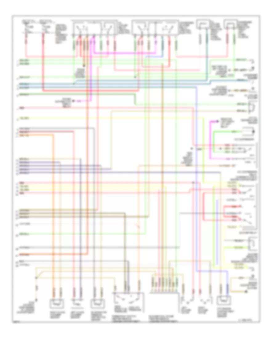
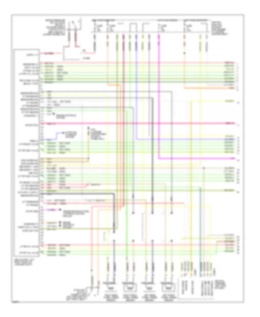
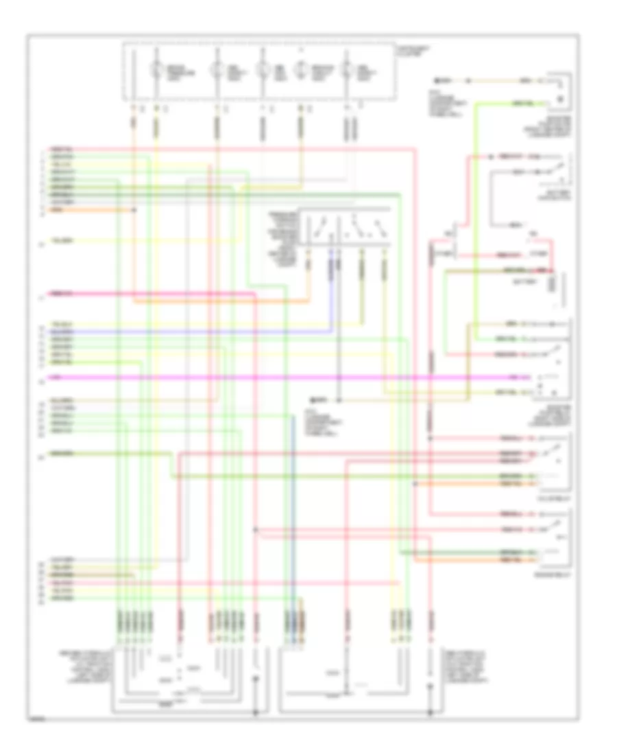
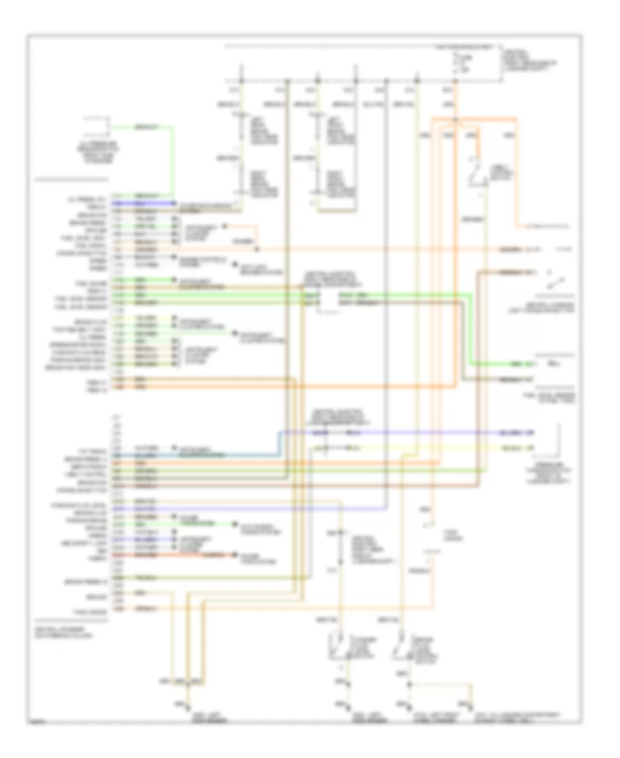
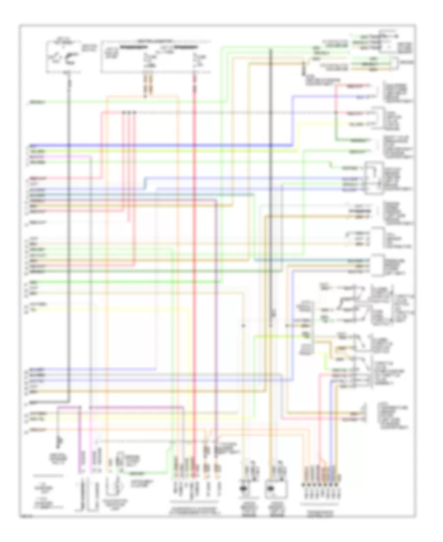
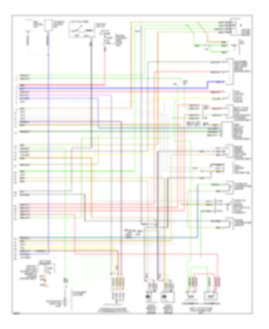
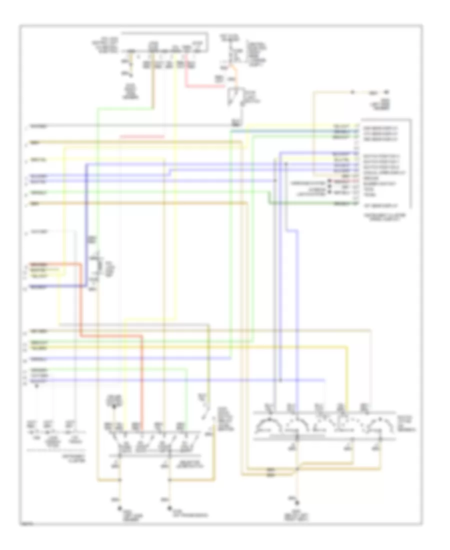
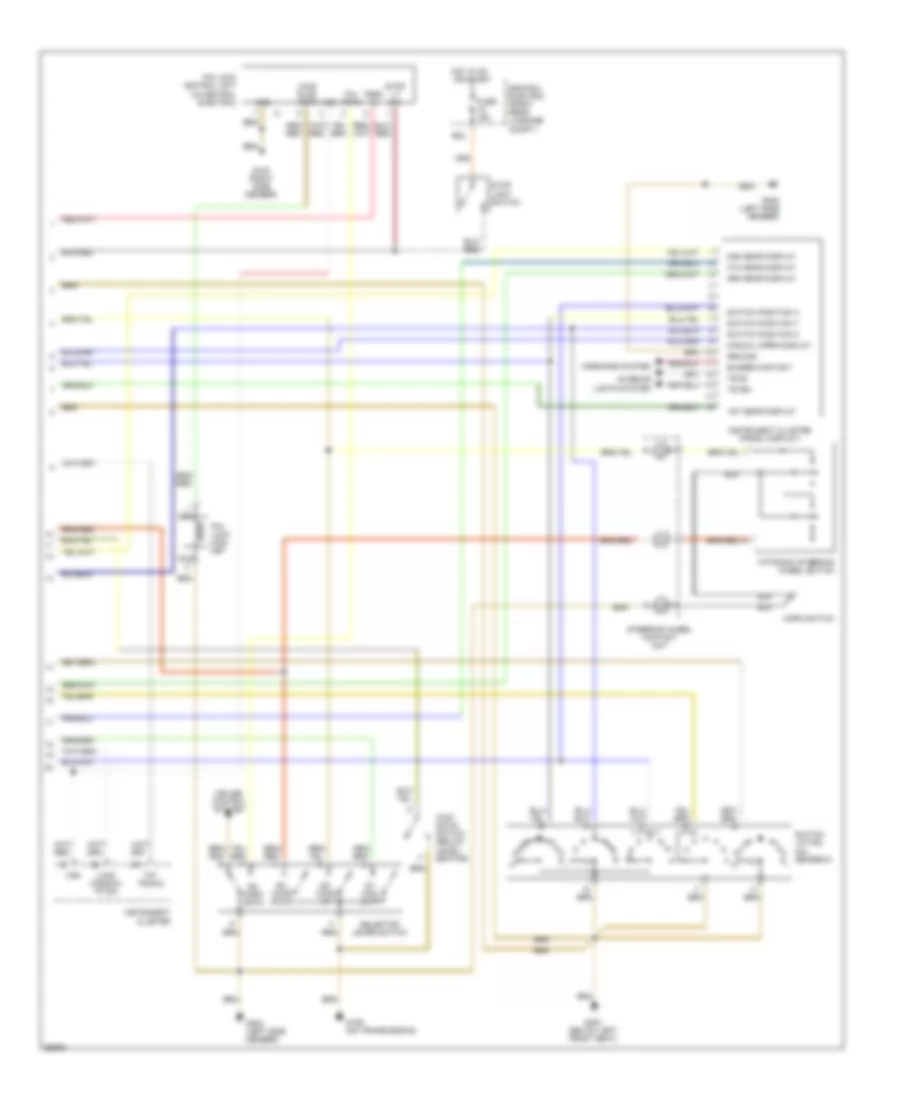
3.6L, Engine Performance Wiring Diagrams (2 of 2) for Porsche 911 Carrera 4 1995
List of elements for 3.6L, Engine Performance Wiring Diagrams (2 of 2) for Porsche 911 Carrera 4 1995:
- * w/
- ** w/o on-board
- on-board
- unit
- "k" lead
- "l" lead
- (on throttle valve assy)
- * * rev. counter
- * rev. counter
- Acc
- Air flow sensor (center left of engine compartment)
- B14
- B15
- Bridge
- Bridge (w/m027 only)
- Central electric
- Central informer pin 1/3
- Closed throttle position (switch)
- Diagnosis plug socket (in passenger's footwell)
- Engine speed sensor (left side engine compartment)
- Fuse 15a
- Fuse 7.5a
- G129 center of engine compartment)
- Hall sensor (on distributor)
- Heated oxygen sensor
- Hot at all times
- Hot in run or start
- Idle speed positioner (center of engine compartment)
- Ignition switch
- Instrument cluster
- K31
- Knock sensor 1 (left of engine)
- Knock sensor 2 (top of engine)
- Knocking
- Malfunction indicator lamp
- Mfi+di
- Nca
- Ntc temperature sensor motor (left side of engine compartment)
- Off
- Pin 15
- Pin 21
- Pin 27
- Pin 44
- Pin 45
- Pin 51
- Pin 8
- Pressure sensor (under left seat)
- Red
- Run
- Shift valve resonance flap (center right of engine compartment)
- Start
- T16 conn (under left seat)
- Tank venting valve (top of engine)
- Td-
- Term 15e
- Term 30
- Term.15
- Term.30
- Throttle valve potentiometer (on throttle valve assembly)
- Throttle valve switch
- Transmission control unit
- W/ catalytic converter
- W/o catalytic converter
- Wide open throttle (switch)
- With auto trans
- With manual trans
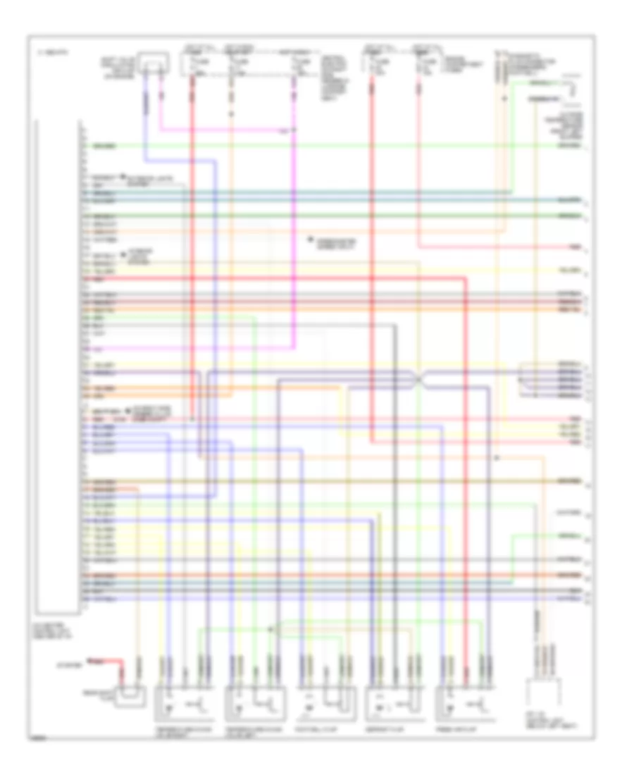
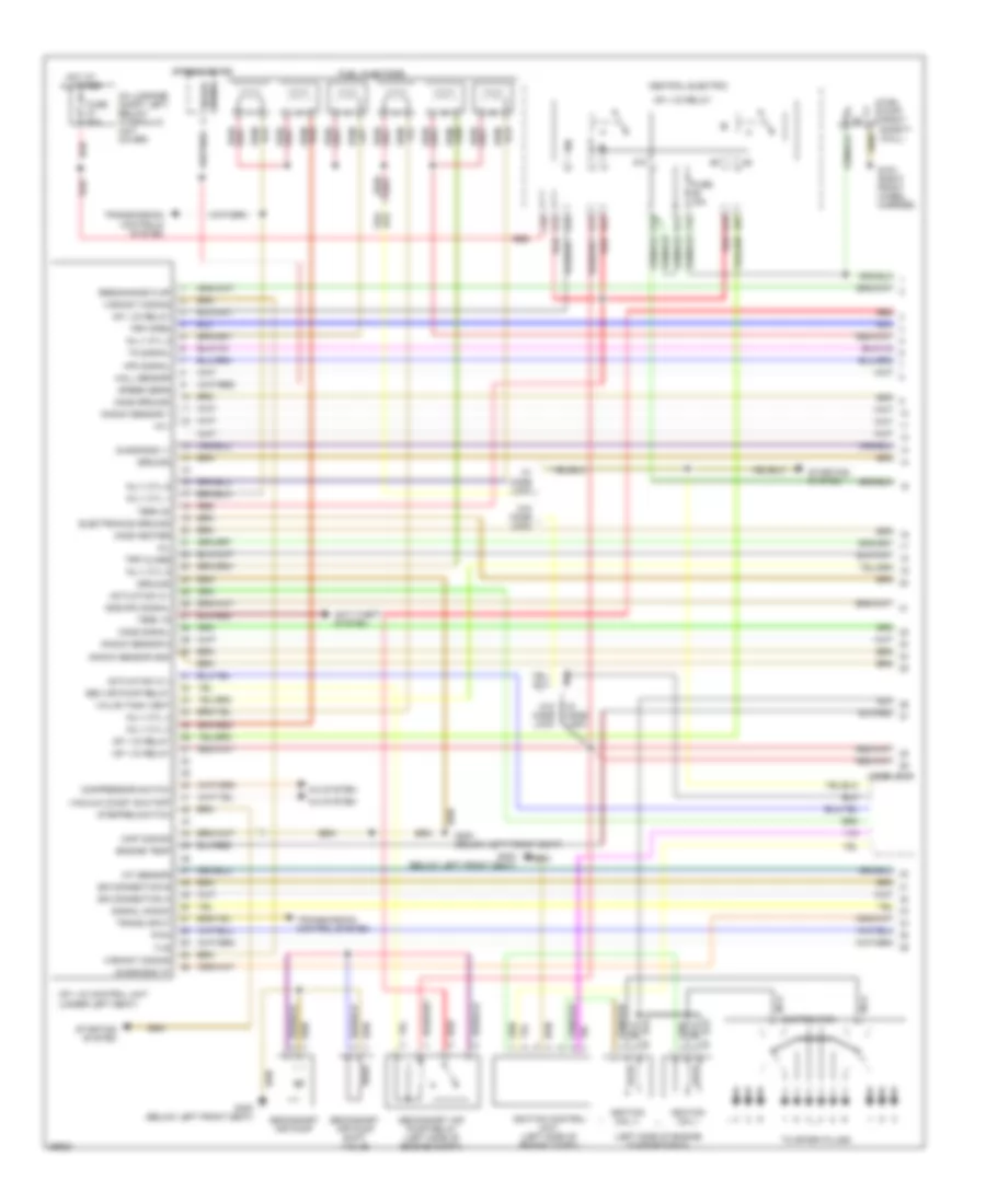
3.6L, Engine Performance Wiring Diagrams, Early Production (1 of 2) for Porsche 911 Carrera 4 1995
List of elements for 3.6L, Engine Performance Wiring Diagrams, Early Production (1 of 2) for Porsche 911 Carrera 4 1995:
- (in luggage compt left, below hydraulic unit cover)
- (left side of engine compartment)
- (under left seat)
- +5 v
- 85b
- 87b
- A/c system
- Actuation ic i
- Actuation ic ii
- Anti-theft system
- C35
- C45
- Central electric
- Code lock
- Compressor switch
- D11
- Diagnosis "k"
- Diagnosis "l"
- Distributor
- Electronics ground
- Engine temp
- Fuel injectors
- Fuel pump (right safety wall)
- Fuse 15a
- Fuse 60a
- G103 (right front wheel carrier)
- G300 (below left front seat)
- Gnd/hfm signal
- Ground
- Hall sensor
- Hfm signal
- Ho2s ground
- Ho2s heater
- Ho2s signal
- Hot at all times
- Iat sensor
- Ignition coil i
- Ignition coil ii
- Ignition control unit (left side of engine compt)
- Inj v cyl 1
- Inj v cyl 2
- Inj v cyl 3
- Inj v cyl 4
- Inj v cyl 5
- Inj v cyl 6
- Knock sensor 1
- Knock sensor 2
- Knock sensor gnd
- Map coding
- Mfi + di control unit
- Mfi + di relay
- Mil
- Nca
- O15
- O24
- O25
- O35
- Pwm
- Red
- Resonance flap
- Sec air pump relay
- Secondary air pump
- Secondary air pump relay (left side of engine compt)
- Secondary air pump shift valve
- Signal knock
- Speed sens
- Speed signal
- Speedometer
- Ss connection a
- Ss connection b
- Starting system
- Stepped switch
- Term 15
- Term 30
- Tn signal
- To spark plugs
- Trans input
- Transmission control system
- Transmission controls system
- Trp close
- Trp open
- Tvs
- Vacuum coast shutoff
- Valve tank vent
- Variant coding
- W/ code lock
- W/0 code lock
- W/o code lock
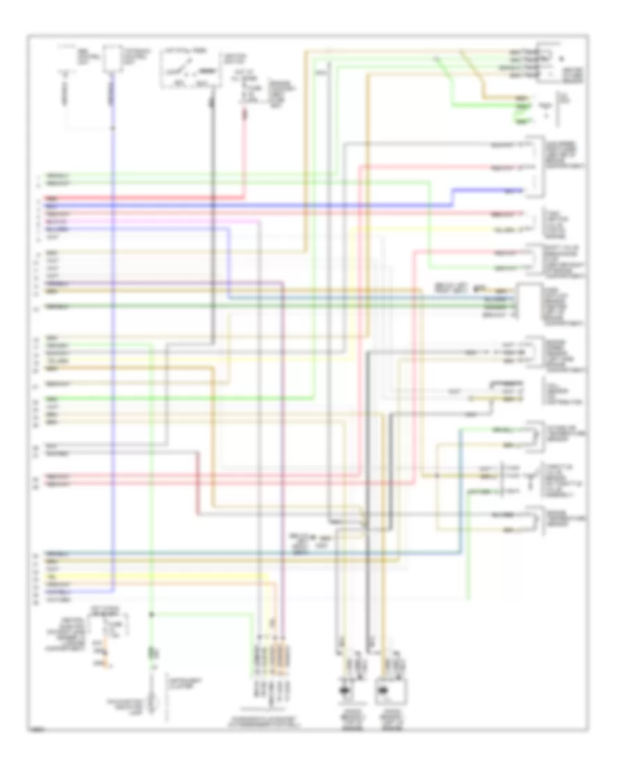
3.6L, Engine Performance Wiring Diagrams, Early Production (2 of 2) for Porsche 911 Carrera 4 1995
List of elements for 3.6L, Engine Performance Wiring Diagrams, Early Production (2 of 2) for Porsche 911 Carrera 4 1995:
- "k" lead
- "l" lead
- (below left front seat)
- (below left g300
- Abs control unit
- Acc
- B15
- Central electric (on right side member, in luggage compartment)
- Co pot
- Diagnosis plug socket (in passenger's footwell)
- Engine compart- ment fuse box
- Engine speed sensor (left side engine compartment)
- Engine temperature sensor
- Front seat)
- Fuse 40a
- Fuse 7.5a
- G300
- Hall sensor (on distributor)
- Heated oxygen sensor
- Hot at all times
- Hot in run or start
- Idle speed positioner (center of engine compartment)
- Ignition switch
- Instrument cluster
- Intake air temperature sensor
- Knock sensor 1 (left of engine)
- Knock sensor 2 (top of engine)
- Knocking
- Lock
- Malfunction indicator lamp
- Mass air flow sensor (center left of engine compartment)
- Mfi+di
- Nca
- Red
- Run
- Shift valve resonance flap (center right of engine compartment)
- Start
- Tank venting valve (top of engine)
- Throttle valve sensor (on throttle valve assembly)
- Tiptronic control unit
- Tn sig
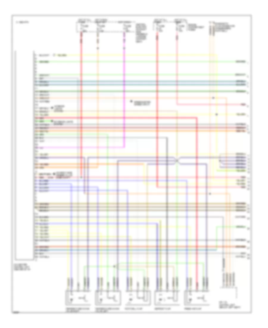
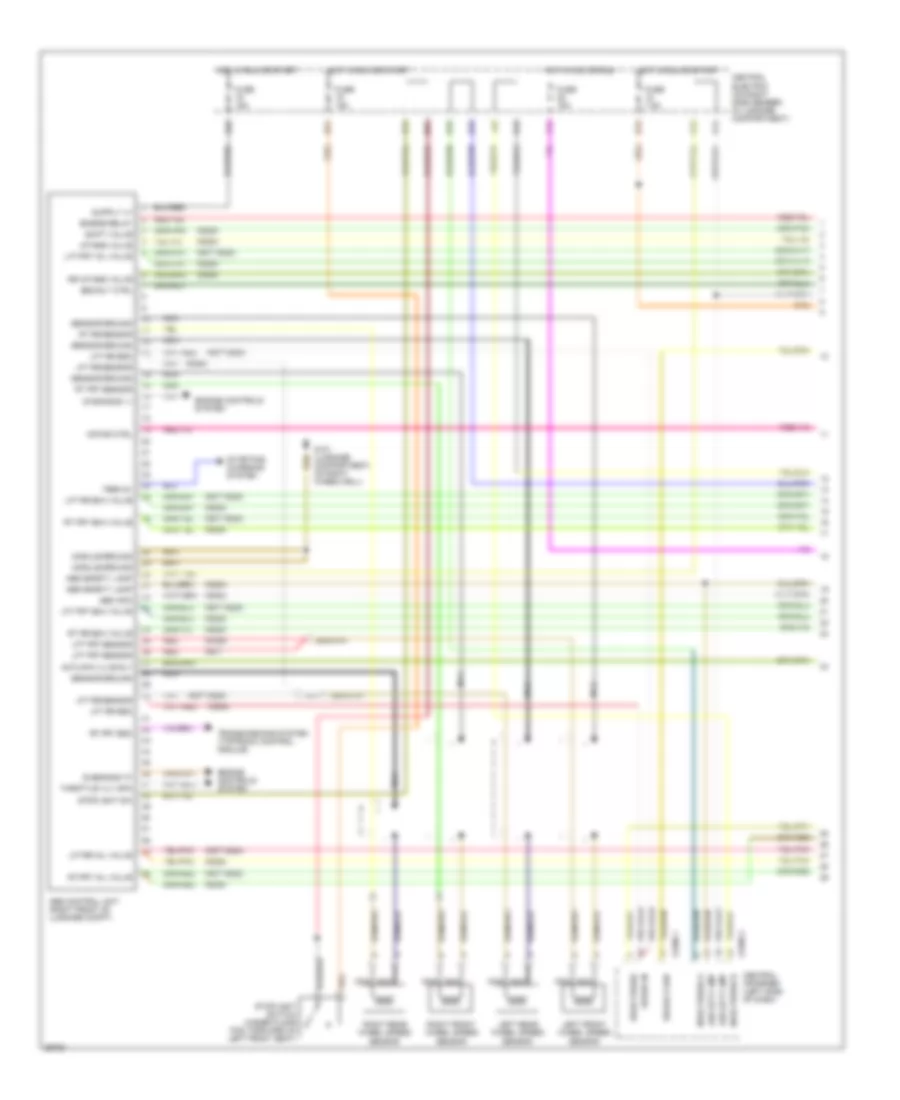
3.6L, Engine Performance Wiring Diagrams, Late Production (1 of 2) for Porsche 911 Carrera 4 1995
List of elements for 3.6L, Engine Performance Wiring Diagrams, Late Production (1 of 2) for Porsche 911 Carrera 4 1995:
- (in luggage compt left, below hydraulic unit cover)
- (left side of engine compartment)
- (under left seat)
- +5 v
- 85b
- 87b
- A/c system
- Actuation ic i
- Actuation ic ii
- Anti-theft system
- Battery
- C35
- C45
- Central electric
- Compressor switch
- D11
- Diagnosis "k"
- Diagnosis "l"
- Distributor
- Electronics ground
- Engine temp
- Exc. rs
- Exc. rs rs
- Fuel injectors
- Fuel pump (right safety wall)
- Fuse 15a
- Fuse 60a
- G103 (right front wheel carrier)
- G300 (below left front seat)
- Gnd/hfm signal
- Ground
- H13
- Hall sensor
- Hfm signal
- Ho2s ground
- Ho2s heater
- Ho2s signal
- Hot at all times
- Iat sensor
- Ignition coil i
- Ignition coil ii
- Ignition control unit (left side of engine compt)
- Inj v cyl 1
- Inj v cyl 2
- Inj v cyl 3
- Inj v cyl 4
- Inj v cyl 5
- Inj v cyl 6
- J43
- Knock sensor 1
- Knock sensor 2
- Knock sensor gnd
- Map coding
- Mfi + di control unit
- Mfi + di relay
- Mil
- Nca
- O15
- O24
- O25
- O35
- Pwm
- Red
- Resonance flap
- Sec air pump relay
- Secondary air pump
- Secondary air pump relay (left side of engine compt)
- Secondary air pump shift valve
- Signal knock
- Speed sens
- Speed signal
- Speedometer
- Ss connection a
- Ss connection b
- Starting system
- Stepped switch
- Term 15
- Term 30
- Tn signal
- To spark plugs
- Trans input
- Transmission control system
- Transmission controls system
- Trp close
- Trp open
- Tvs
- Vacuum coast shutoff
- Valve tank vent
- Variant coding
3.6L, Engine Performance Wiring Diagrams, Late Production (2 of 2) for Porsche 911 Carrera 4 1995
List of elements for 3.6L, Engine Performance Wiring Diagrams, Late Production (2 of 2) for Porsche 911 Carrera 4 1995:
- "k" lead
- "l" lead
- (below left front seat)
- (below left g300
- 10a
- Abs control unit
- Acc
- B15
- Central electric (on right side member, in luggage compartment)
- Co pot
- Cylinder 1-3
- Cylinder 4-6
- Diagnosis plug socket (in passenger's footwell)
- Engine compart- ment fuse box
- Engine speed sensor (left side engine compartment)
- Engine temperature sensor
- Exc. rs
- Front seat)
- Fuse 40a
- Fuse 7.5a
- G300
- Hall sensor (on distributor)
- Heated oxygen sensor
- Hot at all times
- Hot in run or start
- Idle speed positioner (center of engine compartment)
- Ignition switch
- Instrument cluster
- Intake air temperature sensor
- Knock sensor 1 (left of engine)
- Knock sensor 2 (top of engine)
- Knocking
- Lock
- Malfunction indicator lamp
- Mass air flow sensor (center left of engine compartment)
- Nca
- Red
- Run
- Shift valve intake pipe change-over (rs)
- Shift valve resonance flap (center right of engine compartment)
- Start
- Tank venting valve (top of engine)
- Throttle valve sensor (on throttle valve assembly)
- Tiptronic control unit
- Tn sig
EXTERIOR LIGHTS
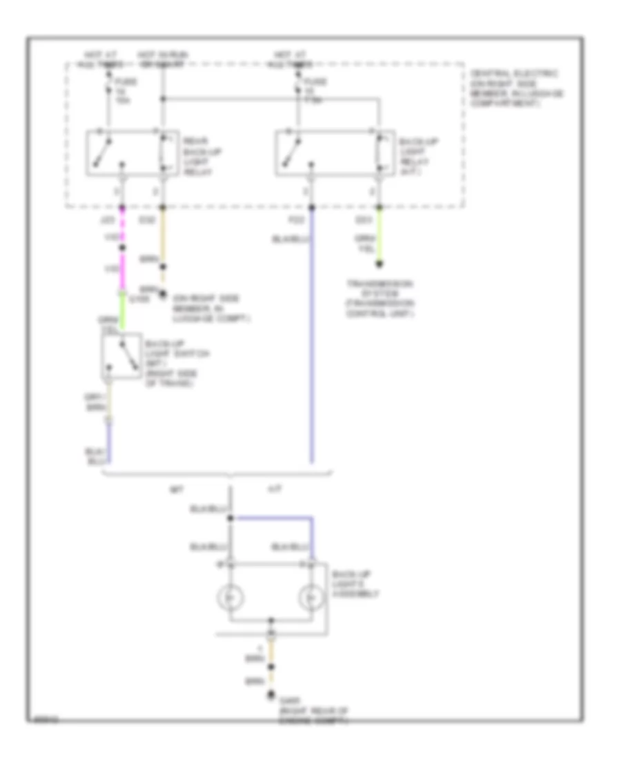
Back-up Lamps Wiring Diagram for Porsche 911 Carrera 4 1995
List of elements for Back-up Lamps Wiring Diagram for Porsche 911 Carrera 4 1995:
- (on right side member, in luggage compt)
- A/t
- Back-up light relay (a/t)
- Back-up light switch (m/t) (right side of trans)
- Back-up lights assembly
- Central electric (on right side member, in luggage compartment)
- D32
- D33
- F22
- Fuse 15a
- Fuse 7.5a
- G105
- G405 (right rear of engine compt)
- Hot at all times
- Hot in run or start
- J23
- M/t
- Rear back-up light relay
- Transmission system (transmission control unit)
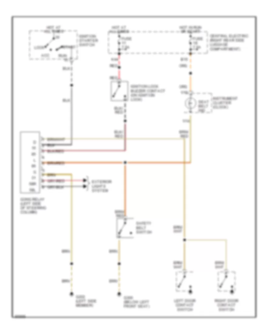
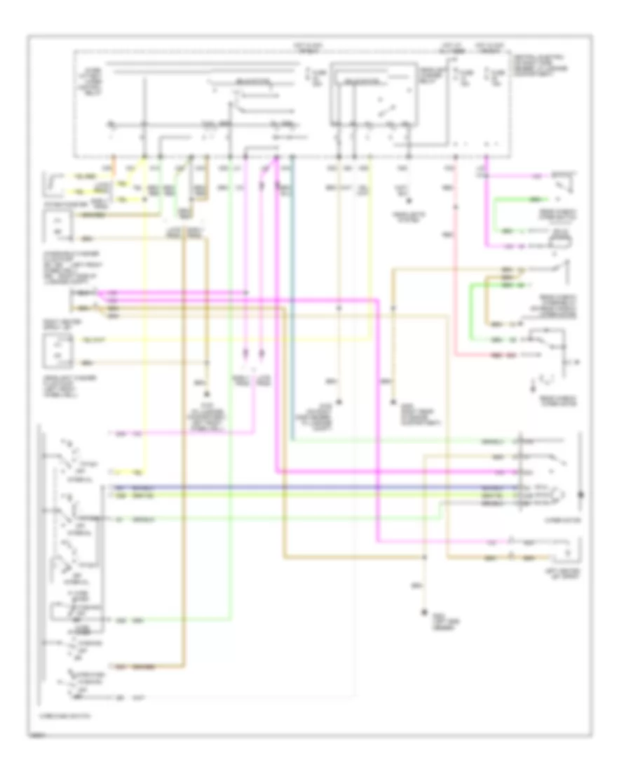
Exterior Lamps Wiring Diagram for Porsche 911 Carrera 4 1995
List of elements for Exterior Lamps Wiring Diagram for Porsche 911 Carrera 4 1995:
- 1 off 2 park 3 head
- 1/2
- 1/3
- 1/5
- 1/6
- 58l
- 58r
- Acc
- Anti-theft system (central alarm locking control unit)
- Bridge
- Central electric (on right side member, in luggage compartment)
- D11
- D12
- D24
- D34
- D35
- E13
- E14
- Early prod
- F24
- F35
- F44
- Flasher
- Fuse 15a
- Fuse 7.5a
- G105 (on right side member, in luggage compartment)
- G202 (left side member)
- G405 (right rear of engine compartment)
- Gong relay (left side of steering column)
- Hazard light switch
- High mounted stop light
- Hot at all times
- Hot in run or start
- Ignition starter switch
- Instrument cluster (clock)
- Instrument light control unit (left side of luggage compt)
- K23
- K25
- Late prod
- Left front turn signals
- Left license plate light
- Left side marker light
- Left tail light assembly
- Left turn ind.
- Light switch
- Lock
- M22
- M34
- N32
- On ind
- Rear defogger (coupe)
- Red
- Revolution counter
- Right front turn signals
- Right license plate light
- Right side marker light
- Right tail light assembly
- Right turn ind.
- Run
- Side marker ind.
- Start
- Stop lamp switch (top of brake pedal support)
- Turn signal switch
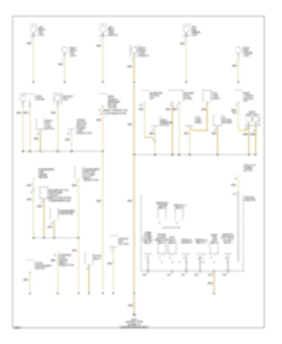
GROUND DISTRIBUTION
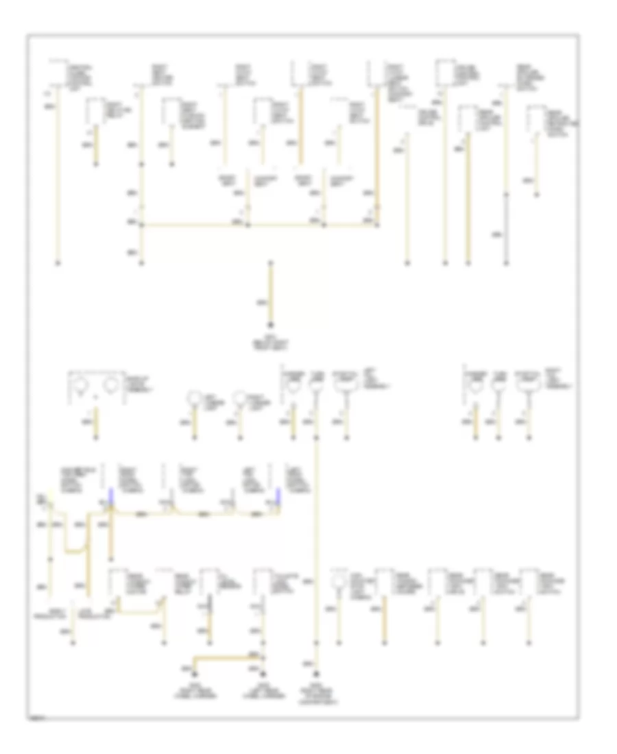
Ground Distribution Wiring Diagram (1 of 6) for Porsche 911 Carrera 4 1995
List of elements for Ground Distribution Wiring Diagram (1 of 6) for Porsche 911 Carrera 4 1995:
- (early production)
- (late production)
- A23
- Ac/heater control unit
- Ashtray light
- Blower final stage
- C43
- Catalytic thermo switch
- Central electric
- Cigar lighter
- Control unit p/n lock
- D32
- Diagnosis plug socket (early production)
- Driver's switch for power window regulator motor passenger's side
- Front fog light relay
- Front fog light switch
- G105 (on right side member, in luggage compartment)
- Glove compartment contact
- Headlight washer relay
- J12
- J22
- K/1
- L45
- Left front fog light
- Left front turn signals
- Left side marker light
- Level pressure switch
- Mirror heating switch (cabrio late production)
- Oil cooler blower
- Passenger's side driver
- Passenger's side lock cylinder
- Passenger's side mirror heater
- Power window regulator relay
- Rear fog light/back- up light relay
- Rear window defogger switch (coupe)
- Right front fog light
- Right front turn signals
- Right headlight
- Right litronic control unit
- Right side marker light
- Start relay
- Sun- roof relay
- Terminal 15e relay
- Terminal x relay
- Terminal x relay iii
- Two- tone horn 1
- Two- tone horn 2
- Wiper inter- mittent control relay
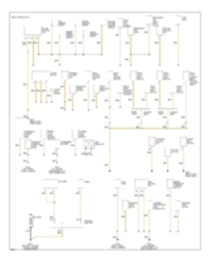
Ground Distribution Wiring Diagram (2 of 6) for Porsche 911 Carrera 4 1995
List of elements for Ground Distribution Wiring Diagram (2 of 6) for Porsche 911 Carrera 4 1995:
- Abs control unit
- Amplifier
- Battery
- Booster pump motor
- Booster pump relay
- Brake fluid level control switch
- Brake pressure warning switch
- Central electric
- Clutch switch
- Code lock
- Coding plug socket
- Comfort seat
- Condenser blower
- D44
- D45
- E15
- Early production
- Engine speed sensor shield
- Fuel pump
- G100 (in luggage compartment, on left wheelwell)
- G101 (in luggage compartment, on right wheelwell)
- G102 (left front wheel carrier)
- G103 (right front wheel carrier)
- G104 (battery, on left side of luggage compartment)
- G300 (below left front seat)
- Hall sensor shield
- Headlight washer fluid pump
- Heated oxygen sensor shield
- Ignition control unit
- Knock sensor 1 shield
- Knock sensor 2 shield
- Left headlight
- Lifting switch
- Luggage compartment lock microswitch
- Mass air flow sensor
- Mfi+ dfi control unit
- Nca
- Park/ neutral control unit
- Radio
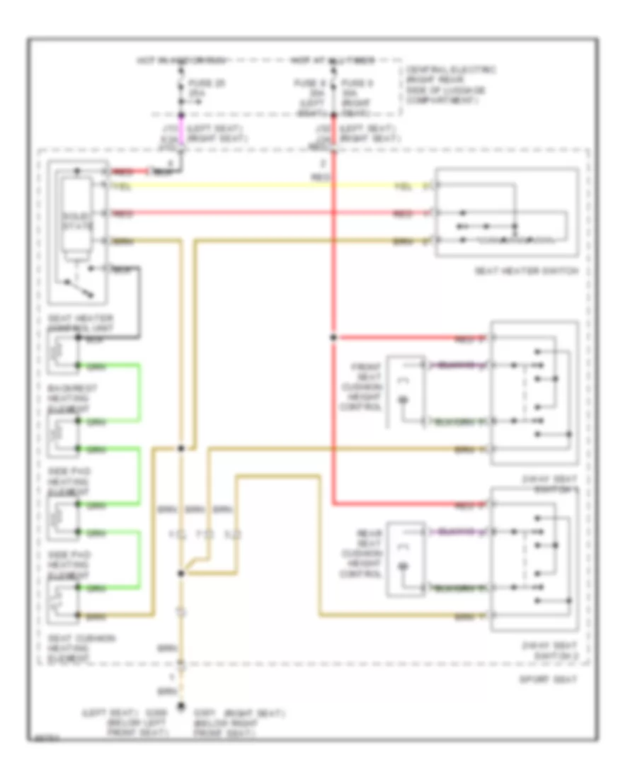
- Right 2-way seat switch
- Right 4-way lumbar seat switch (comfort seat)
- Right 4-way seat switch
- Right delaying relay
- Right seat cushion heating element
- Right seat heater switch
- Safety belt switch
- Secondary air pump
- Secondary air pump shift valve
- Selector lever switch
- Sport seat
- Tiptronic control unit
- Washer fluid level switch
- Windshield washer fluid pump
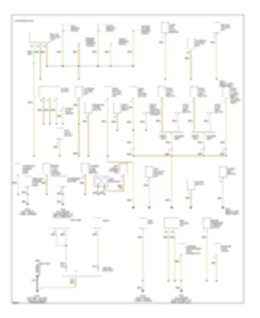
Ground Distribution Wiring Diagram (3 of 6) for Porsche 911 Carrera 4 1995
List of elements for Ground Distribution Wiring Diagram (3 of 6) for Porsche 911 Carrera 4 1995:
- Abs control unit
- Amplifier
- Anti- drive off control unit
- Battery
- Booster pump motor
- Brake fluid level control switch
- Brake pressure warning switch
- Central electric
- Clutch switch
- Coding plug socket
- Comfort seat
- Condenser blower
- D44
- D45
- E15
- Engine speed sensor shield
- Fuel pump
- G100 (in luggage compartment, on left wheelwell)
- G101 (in luggage compartment, on right wheelwell)
- G102 (left front wheel carrier)
- G103 (right front wheel carrier)
- G104 (battery, on left side of luggage compartment)
- G300 (below left front seat)
- Hall sensor shield
- Headlight washer fluid pump
- Heated oxygen sensor shield
- Ignition control unit
- Kick- down switch
- Knock sensor 1 shield
- Knock sensor 2 shield
- Late production
- Left headlight
- Left litronic control unit
- Lifting switch
- Luggage compartment lock microswitch
- Mass air flow sensor
- Mfi+ dfi control unit
- Nca
- Park/ neutral control unit
- Radio
- Right 2-way seat switch
- Right 4-way lumbar seat switch (comfort seat)
- Right 4-way seat switch
- Right delaying relay
- Right seat cushion heating element
- Right seat heater switch
- Safety belt switch
- Selector lever switch
- Sport seat
- Tiptronic control unit
- Washer fluid level switch
- Windshield washer fluid pump
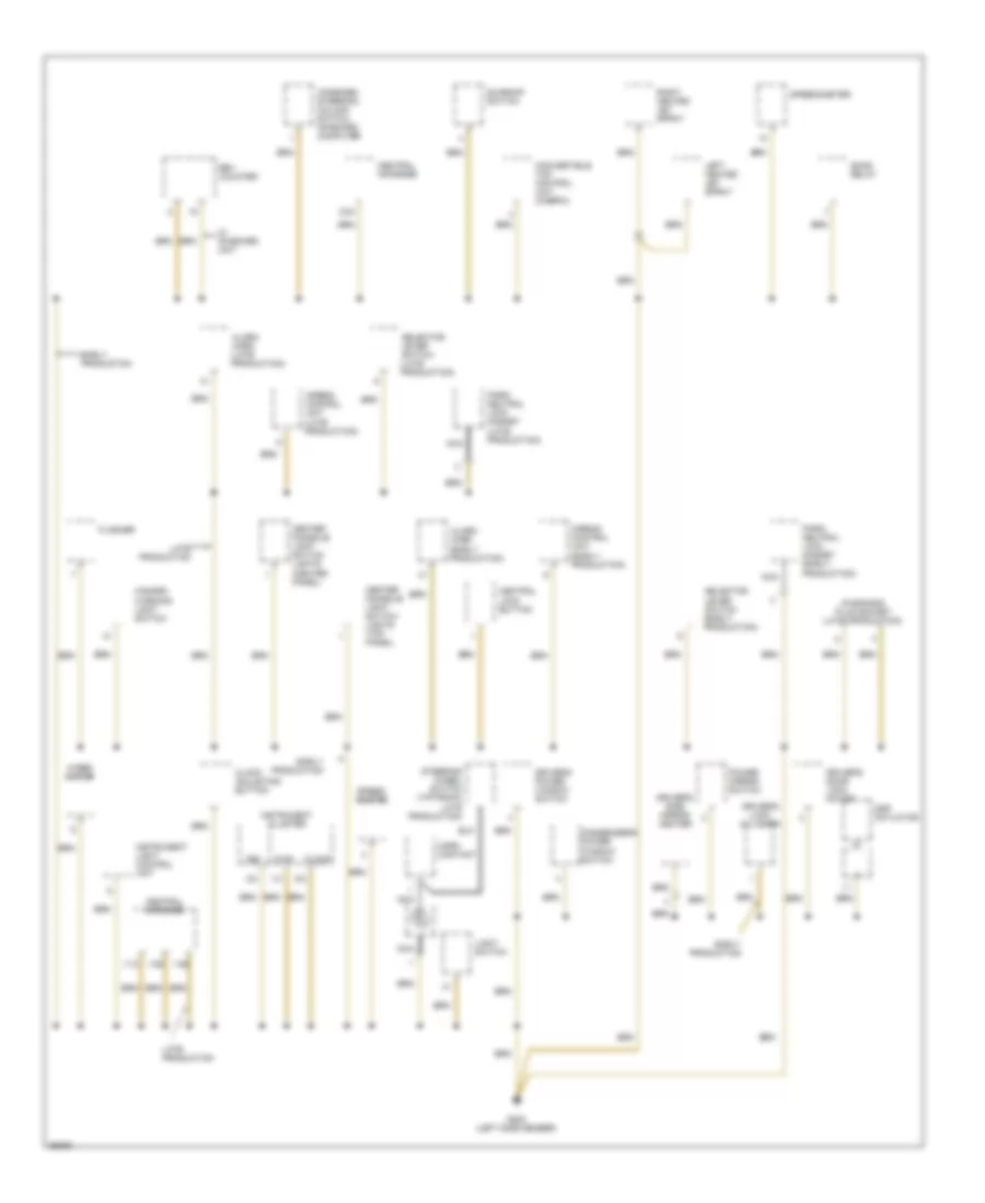
Ground Distribution Wiring Diagram (4 of 6) for Porsche 911 Carrera 4 1995
List of elements for Ground Distribution Wiring Diagram (4 of 6) for Porsche 911 Carrera 4 1995:
- (early production)
- (late production)
- 1/13
- 1/25
- 1/26
- 1/4
- 2/2
- 2/24
- Airbag control unit
- Alarm horn (early production)
- Alarm horn (late production)
- Center console light switch lights (center panel)
- Center console light switch lights (top panel)
- Central informer
- Central lock button
- Clock
- Clock adjusting button
- Combined steering column switch on-board computer
- Convertible top control unit (cabrio)
- D100
- D80
- Diagnosis plug socket (late production)
- Driver's door lock motor
- Driver's lock cylinder
- Driver's power window switch
- Driver's side mirror heater
- Dsp actuator
- Early production
- Flasher
- G202 (left side member)
- Gong relay
- Hazard- warning light switch
- Horn contact
- Instrument cluster
- Instrument light control unit
- Late production
- Left heated jet spray
- Light switch
- Nca
- Park/ neutral lock magnet (early production)
- Park/ neutral lock magnet (late production)
- Passenger's power window switch
- Power mirror switch
- Rev counter
- Right heated jet spray
- Selector lever switch (early production)
- Selector lever switch (late production)
- Speed- ometer
- Speedometer
- Steering wheel switch (tiptronic late production)
- Sunroof switch
- W/ on-board unit
- Wiper motor
Ground Distribution Wiring Diagram (5 of 6) for Porsche 911 Carrera 4 1995
List of elements for Ground Distribution Wiring Diagram (5 of 6) for Porsche 911 Carrera 4 1995:
- (right rear
- 1/2
- Back-up lights assembly
- Central alarm locking control unit
- Comfort seat
- Compartment)
- Convertible top open micro- switch (cabrio)
- Cruise control control unit
- Cruise control drive
- Early production
- G301 (below right front seat)
- G402 (left rear wheel carrier)
- G403 (right rear wheel carrier)
- G405
- High mounted stop light (cabrio)
- Late production
- Left license light
- Left roof micro- switch (cabrio)
- Left tail light assembly
- Left top lock motor (cabrio)
- Marker lamp
- Nca
- Of engine
- Oil level sensor
- Rear package tray drive
- Rear package tray switch
- Rear spoiler control unit
- Rear spoiler extended micro- switch
- Rear spoiler retracted micro- switch
- Rear window defogger (coupe)
- Rear window wiper motor
- Rear window wiper relay
- Right 2-way seat switch
- Right 4-way lumbar seat switch (comfort seat)
- Right 4-way seat switch
- Right delaying relay
- Right license light
- Right roof micro- switch (cabrio)
- Right seat cushion heating element
- Right seat heater switch
- Right tail light assembly
- Right top lock motor (cabrio)
- Sport seat
- Stop/tail lamp
- Tailgate lock micro- switch
- Turn lamp
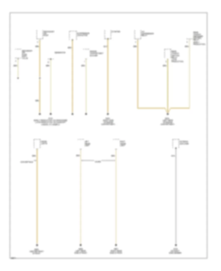
Ground Distribution Wiring Diagram (6 of 6) for Porsche 911 Carrera 4 1995
List of elements for Ground Distribution Wiring Diagram (6 of 6) for Porsche 911 Carrera 4 1995:
- (center front
- (early production)
- (left rear of engine compartment)
- (on right
- (right side of engine compartment)
- A/c compressor relay
- Antenna amplifier
- Convertible
- Coupe
- Engine compartment blower
- G105
- G133 (early production: on crankcase) (late production: on camshaft casing, cylinder 3)
- G403
- G404
- G906 (left rear side of roof)
- G907 (right rear side of roof)
- G908
- Generator
- Inside lights
- Left inside light
- Nca
- Of roof)
- Rear window defogger control relay
- Rear window heating relay (late production)
- Right inside light
- Secondary air pump
- Secondary air pump shift valve
- Side member)
- Starter
- Suppressor capacitor
HEADLIGHTS
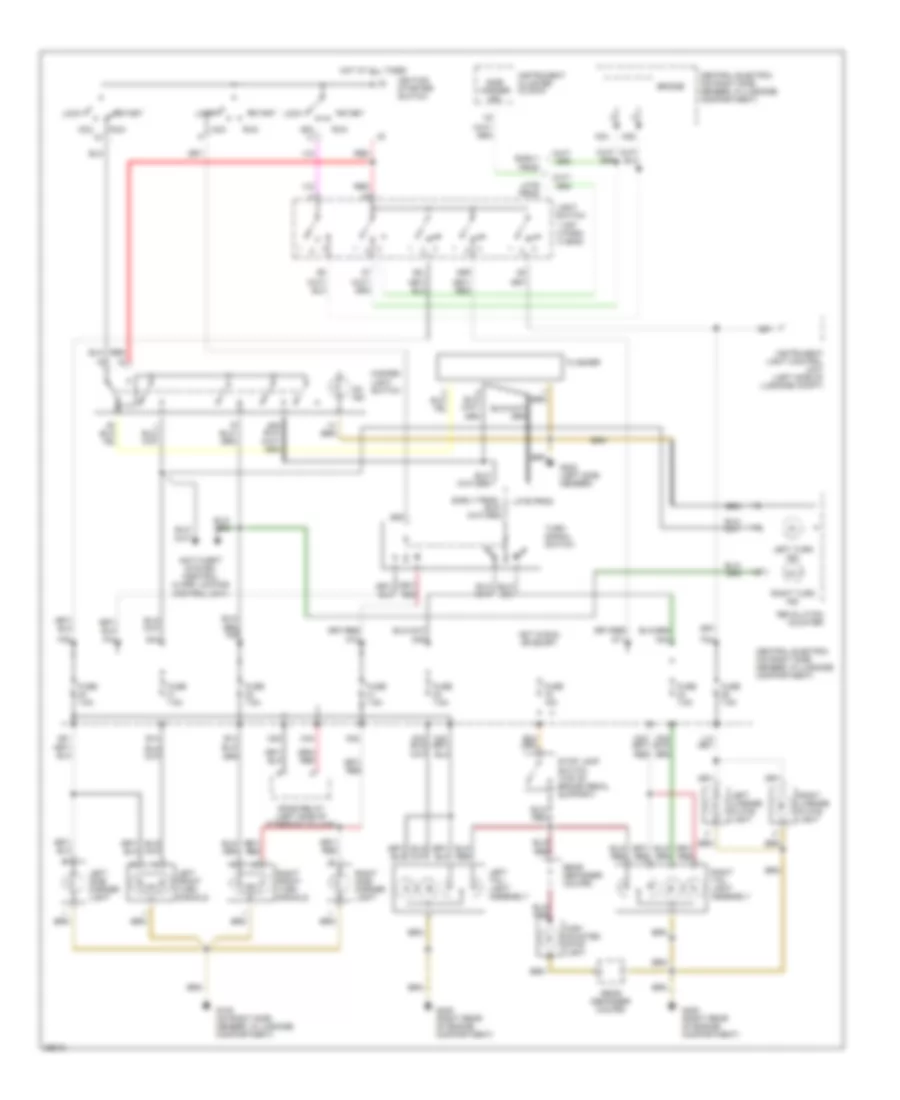
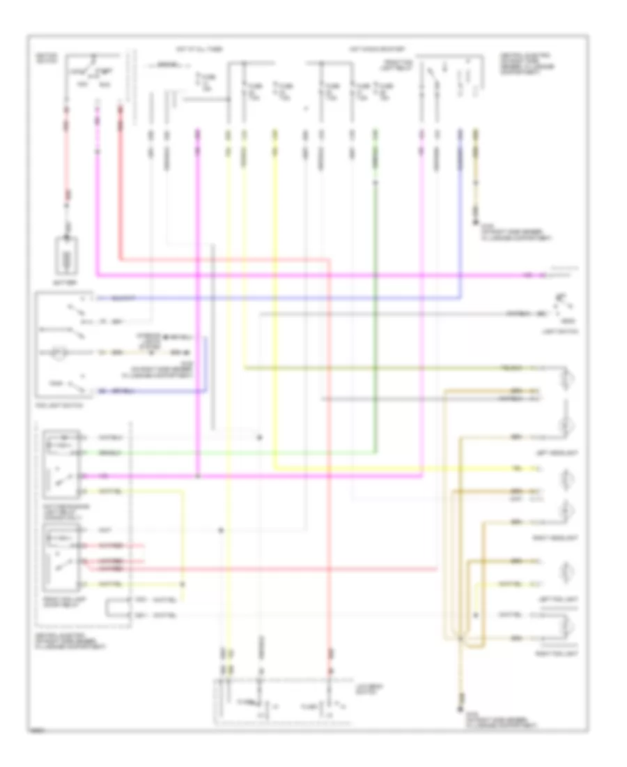
Headlight Wiring Diagram, with Litronic Lighting System for Porsche 911 Carrera 4 1995
List of elements for Headlight Wiring Diagram, with Litronic Lighting System for Porsche 911 Carrera 4 1995:
- 56a
- 56b
- Acc
- B32
- B33
- Battery
- Bridge
- C23
- C24
- C25
- C33
- C45
- Central electric (on right side member, in luggage compartment)
- D32
- D41
- D43
- Daytime running light relay (canada only)
- E11
- F21
- Flash
- Fog light switch
- Front fog lamp on/off relay
- Front fog light relay
- Fuse 15a
- Fuse 7.5a
- G105 (on right side member, in luggage compartment)
- Head
- Hot at all times
- Hot in run or start
- Ignition switch
- Interior lights system
- Js3
- K25
- K35
- L24
- Left fog light
- Left headlight
- Left litronic control unit (luggage compt)
- Light switch
- Lock
- Low beam switch
- Note: handle litronic control units & headlights with extreme caution as high voltages are present during operation
- Off
- Red
- Right fog light
- Right headlight
- Right litronic control unit (luggage compt)
- Run
- Solid state
- Solid state (high voltage)
- Start
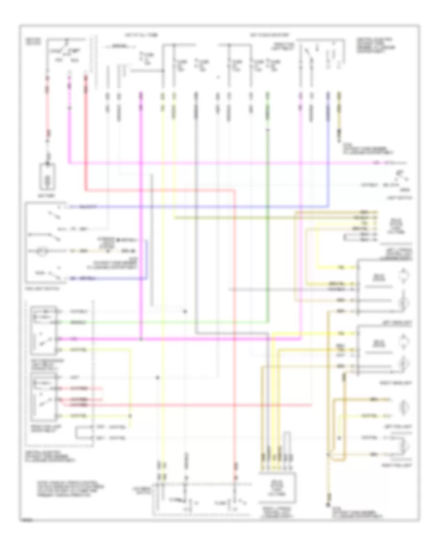
Headlight Wiring Diagram, without Litronic Lighting System for Porsche 911 Carrera 4 1995
List of elements for Headlight Wiring Diagram, without Litronic Lighting System for Porsche 911 Carrera 4 1995:
- 56a
- 56b
- Acc
- B32
- B33
- Battery
- Bridge
- C23
- C24
- C25
- C33
- C45
- Central electric (on right side member, in luggage compartment)
- D32
- D41
- D43
- Daytime running light relay (canada only)
- E11
- F21
- Flash
- Fog light switch
- Front fog lamp on/off relay
- Front fog light relay
- Fuse 15a
- Fuse 7.5a
- G105 (on right side member, in luggage compartment)
- Head
- Hot at all times
- Hot in run or start
- Ignition switch
- Interior lights system
- Js3
- K25
- K35
- L24
- Left fog light
- Left headlight
- Light switch
- Lock
- Low beam switch
- Off
- Red
- Right fog light
- Right headlight
- Run
- Start
HORN
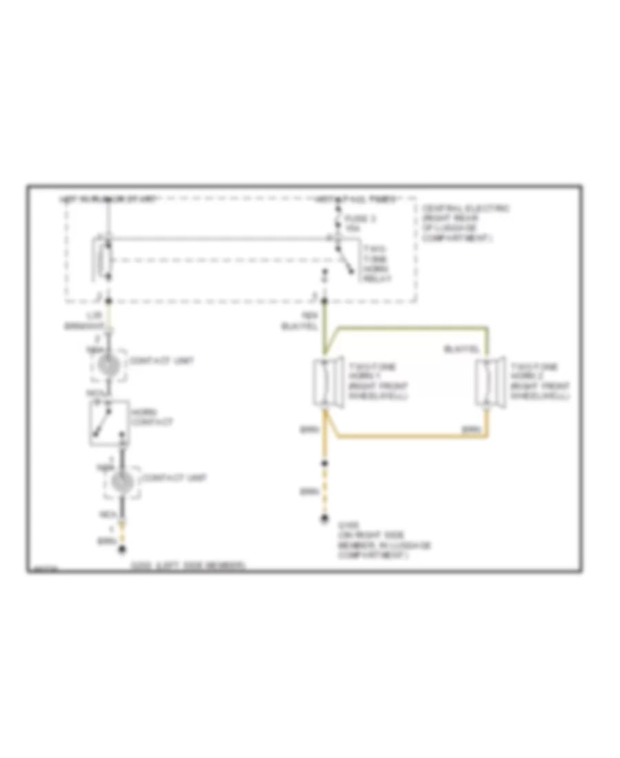
Horn Wiring Diagram for Porsche 911 Carrera 4 1995
List of elements for Horn Wiring Diagram for Porsche 911 Carrera 4 1995:
- (left side member)
- Central electric (right rear of luggage compartment)
- Contact unit
- Fuse 3 15a
- G105 (on right side member, in luggage compartment)
- G202
- Horn contact
- Hot at all times
- Hot in run or start
- L35
- N24
- Nca
- Two- tone horn relay
- Two-tone horn 1 (right front wheelwell)
- Two-tone horn 2 (right front wheelwell)
INSTRUMENT CLUSTER
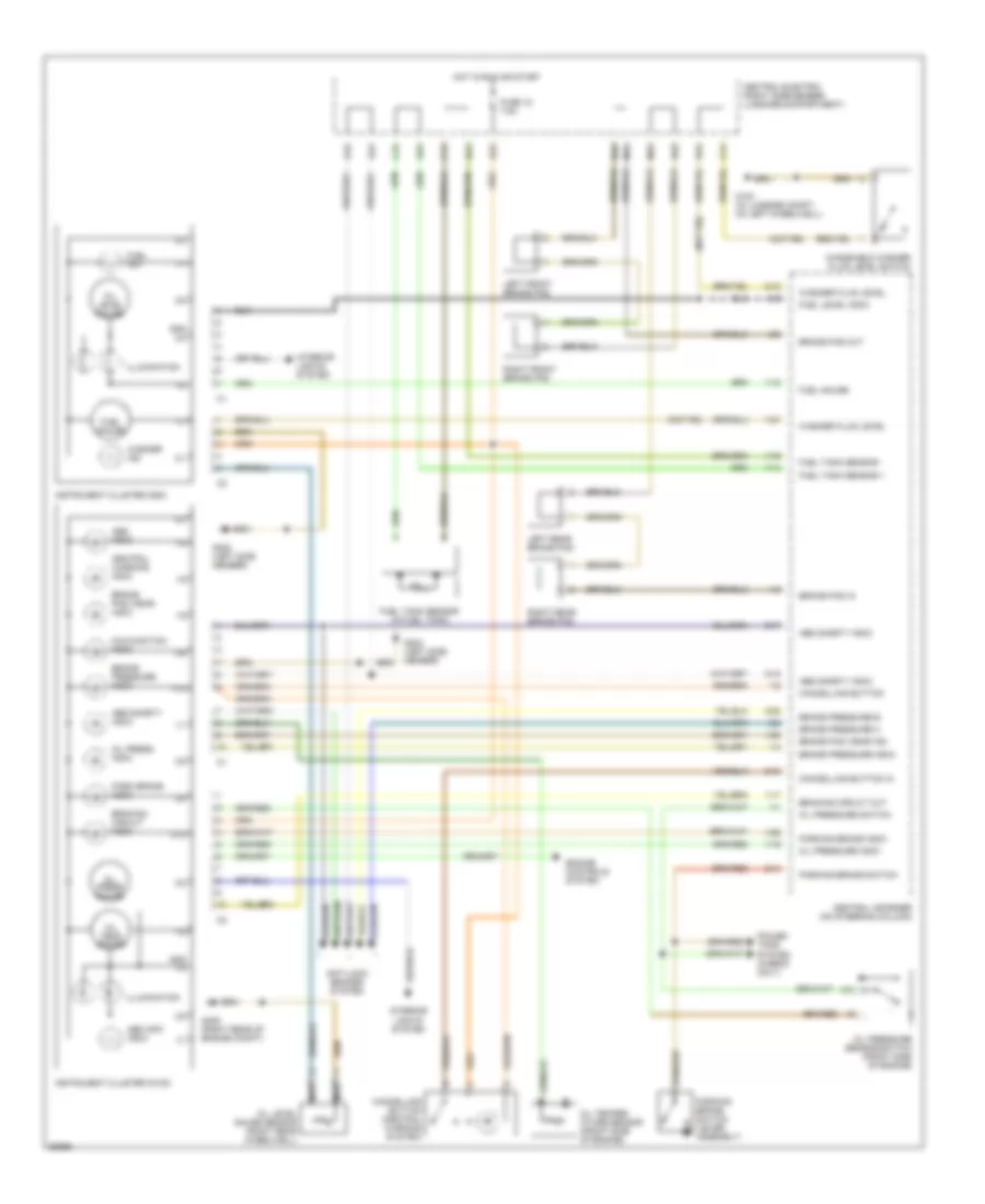
Instrument Cluster Wiring Diagram (1 of 2) for Porsche 911 Carrera 4 1995
List of elements for Instrument Cluster Wiring Diagram (1 of 2) for Porsche 911 Carrera 4 1995:
- (not rs)
- 1/1
- 1/10
- 1/12
- 1/14
- 1/15
- 1/17
- 1/19
- 1/21
- 1/22
- 1/23
- 1/3
- 1/4
- 1/5
- 1/6
- 1/7
- 1/8
- 1/9
- 2/1
- 2/10
- 2/12
- 2/14
- 2/17
- 2/18
- 2/2
- 2/22
- 2/3
- 2/4
- 2/5
- 2/6
- 2/8
- 2/9
- Abd info indic
- Abd safety indic
- Abs indic
- Abs safety indic
- Anti-lock brakes system
- B15
- B41
- B42
- B44
- Brake pad in
- Brake pad out
- Brake pad wear ind
- Brake pad wear indic
- Brake pressure a
- Brake pressure b
- Brake pressure indic
- Braking circuit indic
- Braking circuit out
- C11
- C12
- C14
- Cancelling button
- Cancelling button (central warning system)
- Cancelling button in
- Central electric (right side member, luggage compartment)
- Central informer (on steering column)
- Central warning indic
- D42
- E12
- Engine controls system
- Fuel gauge
- Fuel ind.
- Fuel level indic
- Fuel tank sensor (in fuel tank)
- Fuel tank sensor +
- Fuel tank sensor -
- Fuse 18 7.5a
- G100 (in luggage compt, on left wheelwell)
- G202 (left side member)
- G405 (right rear of engine compt)
- Gnd 1/4
- Gnd 2/2
- Hot in run or start
- Illumination
- Instrument cluster (d100)
- Instrument cluster (d80)
- Interior lights system
- Left front brake pad
- Left rear brake pad
- M13
- M14
- Malfunction indic
- N43
- N44
- Nca
- Oil level gauge
- Oil level gauge sensor (right rear wheelwell)
- Oil press gauge
- Oil press indic
- Oil pressure indic
- Oil pressure sensor/switch (front side of engine)
- Oil pressure switch
- Oil temp gauge
- Oil temper- ature sensor (front side of engine)
- Park brake indic
- Parking brake indic
- Parking brake switch
- Parking brake switch (lever assembly)
- Power tops system (cabrio only)
- Right front brake pad
- Right rear brake pad
- Washer fluid level
- Washer ind.
- Windshield washer fluid level switch
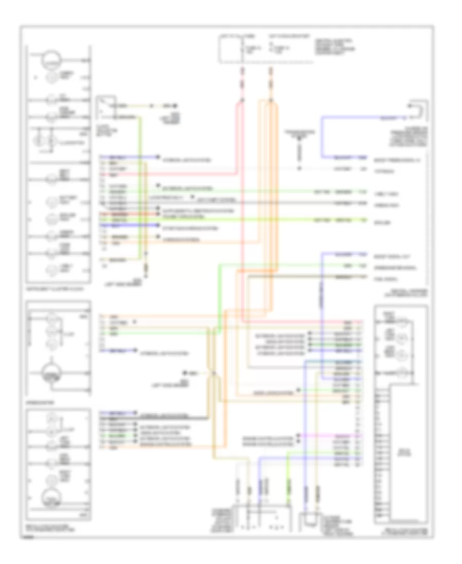
Instrument Cluster Wiring Diagram (2 of 2) for Porsche 911 Carrera 4 1995
List of elements for Instrument Cluster Wiring Diagram (2 of 2) for Porsche 911 Carrera 4 1995:
- (late prod only)
- (not rs)
- (turbo only)
- 1/1
- 1/10
- 1/11
- 1/12
- 1/14
- 1/15
- 1/18
- 1/2
- 1/20
- 1/24
- 1/3
- 1/4
- 1/5
- 1/6
- 1/7
- 1/8
- 1/9
- 2/1
- 2/16
- 2/25
- 2/5
- A/t indic
- Airbag indic
- Anti-theft system
- B15
- Battery indic
- Boost press signal in
- Boost signal out
- Cabrio indic
- Central electric (on right side member, in luggage compartment)
- Central informer (on steering column)
- Charge air pressure sensor (late production turbo model only) (intake ductwork)
- Clock
- Clock adjusting button
- Code lock indic
- Combined steering column switch: on board computer
- Door locks system
- Engine controls system
- Exterior lights system
- Fuel signal
- Fuse 12 15a
- Fuse 18 7.5a
- G202 (left side member)
- Gnd
- Headlights system
- High beam indic
- Hot at all times
- Hot in run or start
- Illum
- Illumination
- Instrument cluster (clock)
- Interior lights system
- K32
- Left turn indic
- Outside temperature sensor (left side of front bumper)
- Power tops system
- Red
- Revolution counter w/ on-board computer
- Revolution counter w/o on-board computer
- Right turn indic
- Seat belt indic
- Side marker indic
- Solid state
- Speed- ometer
- Speedometer
- Speedometer signal
- Spoiler
- Spoiler indic
- Starting/charging system
- Tach- ometer
- Tiptronic
- Transmissions system
- V-belt indic
- Warning systems
INTERIOR LIGHTS
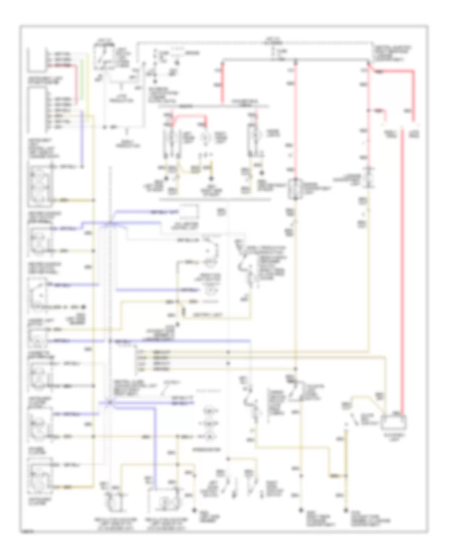
Interior Light Wiring Diagram for Porsche 911 Carrera 4 1995
List of elements for Interior Light Wiring Diagram for Porsche 911 Carrera 4 1995:
- (early production) (late production)
- 1/1
- 1/2
- 1/4
- 1/5
- 1/7
- 2/16
- 2/2
- 2/21
- 2/5
- 2/8
- A/c, heater control unit
- A/t only
- Ashtray light
- Bridge
- Center console light switch (center panel)
- Center console light switch (top panel)
- Central alarm locking control unit (below right front seat)
- Central electric (right rear side luggage compartment)
- Cigarette lighter illum
- Convertible, targa
- Coupe
- Early prod
- Early production
- Engine compartment light
- Exterior lights system (license plate lights)
- F24
- Front fog light switch
- Fuse 7.5a
- G105 (on right side member, in luggage compartment)
- G105 (on right side member, in luggage compt)
- G17
- G202 (left side member)
- G405 (right rear of engine compartment)
- G906 (left side of roof)
- G907 (right side of roof)
- G908 (center front of roof)
- Gauges cluster
- Glove box contact
- Glove box light
- Hazard light switch
- Hot at all times
- Inside lights
- Instrument cluster
- Instrument cluster (clock)
- Instrument light control unit (left side of luggage compt)
- Instrument light potentiometer
- K41
- K43
- K44
- Late prod
- Late production
- Left door contact switch
- Left inside light
- Light switch 1 off 2 park 3 head
- Luggage compartment light
- Mirror heating switch (late prod cabrio)
- Rear window defogger switch (early prod, & late prod coupe)
- Red
- Revolution counter (left side of i/p) (w/ on board unit)
- Revolution counter (left side of i/p) (w/o on board unit)
- Right door contact switch
- Right inside light
- Speedometer
- Tailgate lock micro- switch
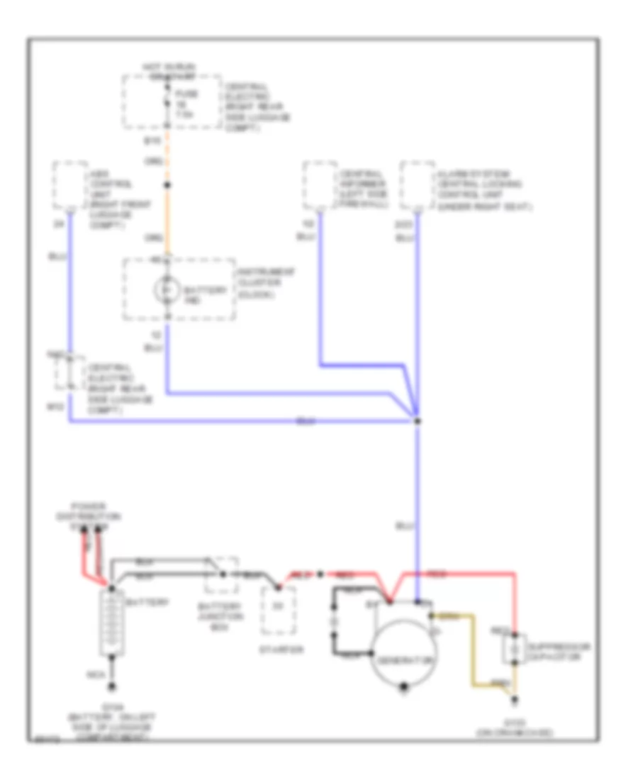
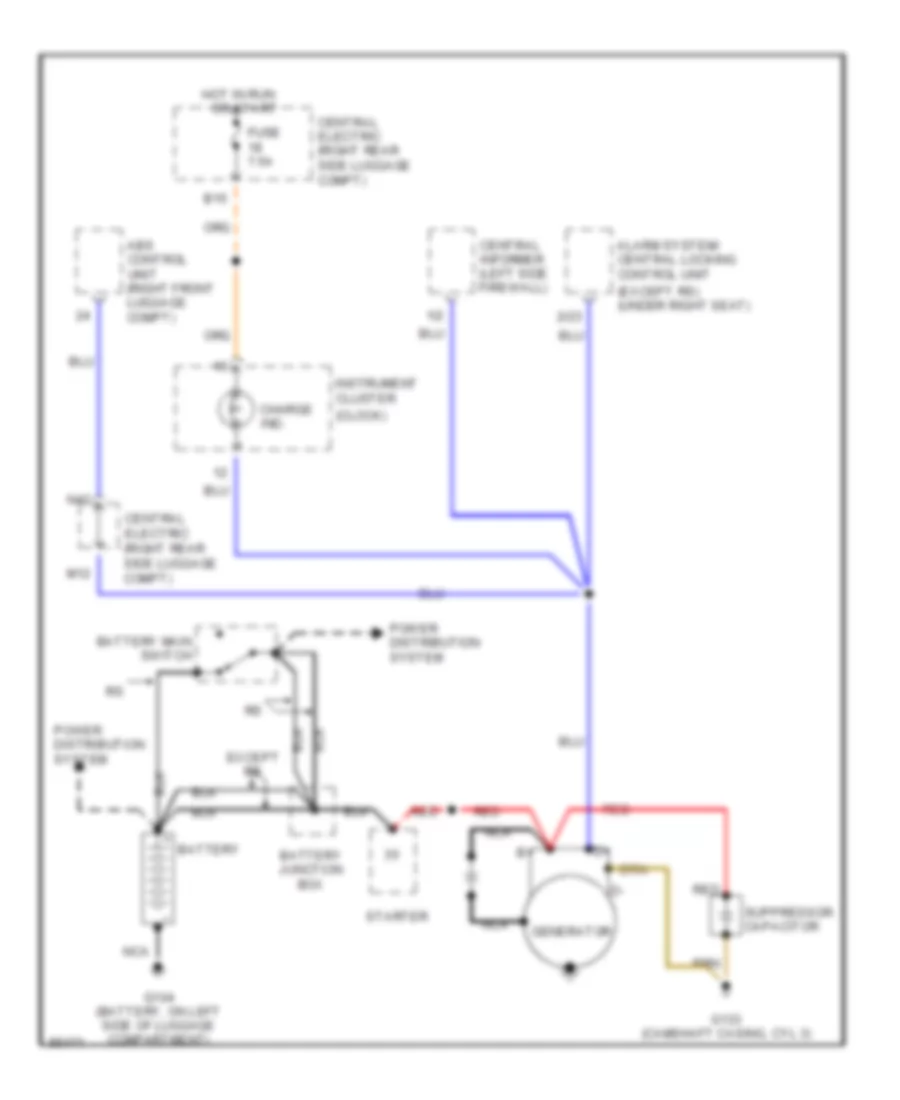
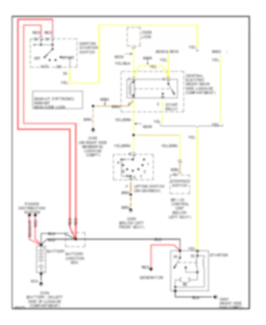
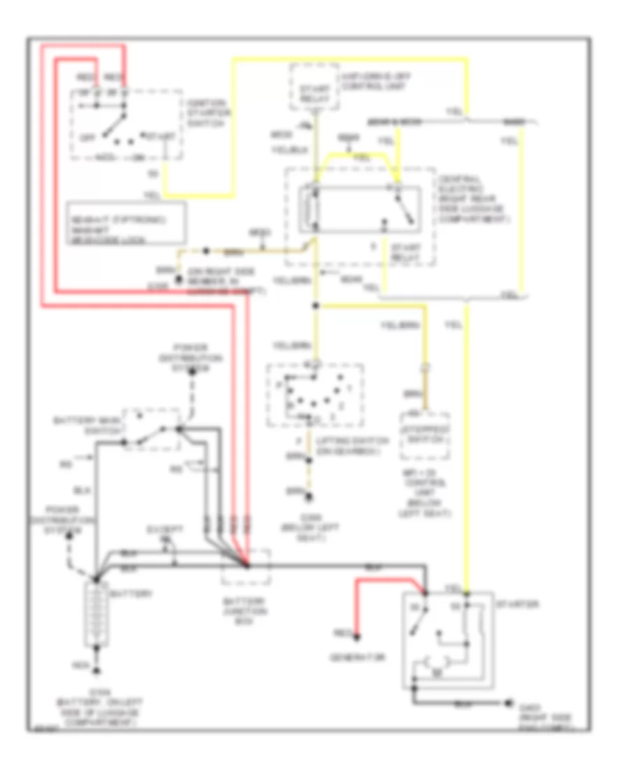
POWER DISTRIBUTION
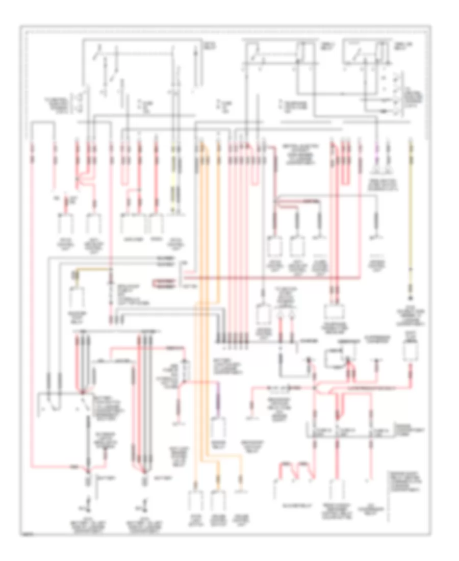
Power Distribution Wiring Diagram (1 of 4) for Porsche 911 Carrera 4 1995
List of elements for Power Distribution Wiring Diagram (1 of 4) for Porsche 911 Carrera 4 1995:
- (emergency shut-off)
- (late production only)
- (not rs)
- 1/4
- 15e
- A/c compressor relay
- Abs fuse 46 60a (hydraulic unit top cover)
- Air bag control unit
- Alarm system control unit
- Amplifier
- Anti- drive off control unit
- Anti-lock brakes system valve relay
- B24
- B25
- B35
- Battery
- Battery junction box (in luggage compartment)
- Blower relay
- Booster pump
- Bpau/pump fuse 47 60a (hydraulic unit top cover)
- C32
- C35
- Central electric (on right side member, in luggage compartment)
- Compartment)
- Control unit
- Cruise control switch
- Cruise control unit
- D32
- Engine compartment fuses
- Engine compt relay center (carrier plate in engine compartment)
- Engine relay
- Exterior lights/ headlights systems
- F42
- F45
- From ignition start switch (diagram 2 of 4)
- Fuse 15a
- Fuse 42 30a
- Fuse 43 25a
- Fuse 44 7.5a
- G104 (battery, on left side of luggage compartment)
- G105 (on right side member, in luggage compartment)
- G12
- G14
- G15
- G23
- Generator
- H13
- H14
- J43
- J44
- M31
- M32
- Main switch (in luggage
- Mfi+di
- Mfi+di control unit
- Mfi+di relay
- Nca
- Not rs
- O31
- R62
- Radio
- Rear window defogger control relay (coupe not rs)
- Red
- Relay
- Secondary air pump relay
- Secondary air pump relay fuse 40a (engine compt)
- Shift flap rear
- Starter
- Stop- light switch
- Suppressor capacitor
- Te 30 red
- Telephone (te 30) fuse 15a
- Telephone transmitter/ reciever
- Term 15e relay
- Term x relay
- To central electric (diagram 2 of 4)
- To ignition start switch (diagram 2 of 4)
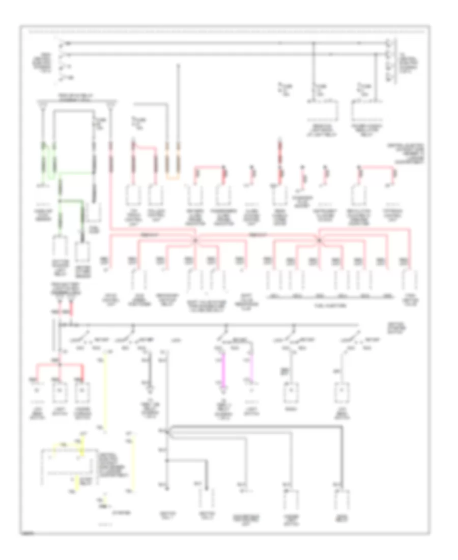
Power Distribution Wiring Diagram (2 of 4) for Porsche 911 Carrera 4 1995
List of elements for Power Distribution Wiring Diagram (2 of 4) for Porsche 911 Carrera 4 1995:
- (diagram 1 of 4)
- (diagram 3 of 4)
- 15e
- A/t
- Acc
- Alarm system control unit
- B21
- Beam switch
- C45
- Central electric (on right side member, in luggage compartment)
- Convertible top control unit
- D12
- D14
- Daytime running light relay
- Diagnosis plug socket
- Driver's alarm primed indicator
- From battery junction box (diagram 1 of 4)
- From central electric (diagram 1 of 4)
- From mfi+di relay
- Fuel injectors
- Fuel pump
- Fuse 15a
- Fuse 30a
- Gong relay
- Hazard
- Hazard light switch
- Heated oxygen sensor
- Idle speed positioner
- Ignition coil 1
- Ignition coil 2
- Ignition starter switch
- Instrument cluster (clock)
- K32
- Light
- Lock
- Low
- M/t
- Mass air flow sensor
- Mfi+di control unit
- Nca
- No.1
- No.2
- No.3
- No.4
- No.5
- No.6
- O15
- P/n lock control unit
- Passenger's alarm primed indicator
- Power window regulator relay
- Radio
- Rear fog light/back- up light relay
- Rear window wiper motor
- Red
- Red 1/3
- Red 53a
- Revolution counter w/ onboard computer
- Run
- Secondary air pump relay
- Shift valve intake pipe change-over valves (rs only)
- Shift valve resonance flap
- Start
- Start relay
- Starter
- Switch
- Tank venting valve
- Tip- tronic control
- Tiptronic control unit
- To central electric
- To term. 15e relay (diagram 1 of 4)
- To term. x relay
- Unit
- Warning switch
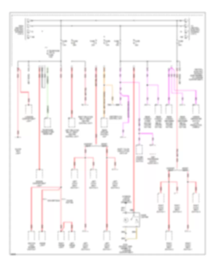
Power Distribution Wiring Diagram (3 of 4) for Porsche 911 Carrera 4 1995
List of elements for Power Distribution Wiring Diagram (3 of 4) for Porsche 911 Carrera 4 1995:
- (late prod only)
- (late production cabrio)
- (not rs or turbo)
- (not rs)
- (not used)
- (on right side
- 15e
- B12
- Central electric (on right side member, in luggage compartment)
- Cigar lighter
- Comfort seat
- Compartment)
- Control unit)
- Convertible
- Coupe (not rs)
- Dsp processor (digital audio only)
- Engine compartment light
- From central electric (diagram 2 of 4)
- Fuse 15a
- Fuse 25a
- Fuse 30a
- Fuse 7.5a
- G105
- G29
- G35
- Glove box light
- Heater & a/c control unit
- Ignition lock buzzer contact
- Inside light
- Interior lights system (rheostat)
- J13
- J25
- J32
- J33
- J34
- K13
- K15
- K34
- K41
- K42
- K43
- K44
- L43
- L44
- Left 2-way seat
- Left 4-way seat
- Left delaying relay (seat heater
- Left inside light
- Luggage
- Luggage compartment light
- Member, in
- Mirror defroster switch
- Not rs)
- Power window switch
- Rear spoiler control
- Rear window defogger
- Rear window wiper
- Red
- Relay (coupe
- Right 2-way seat
- Right 4-way seat
- Right delaying relay (seat heater
- Right inside light
- Shift valve circulating air flap
- Sport seat
- Switch (coupe
- Switch 1
- Switch 2
- Switch 3
- Te 15
- Telephone (te 15) fuse 7.5a
- Telephone transmitter- receiver
- To central electric (diagram 4 of 4)
- Unit
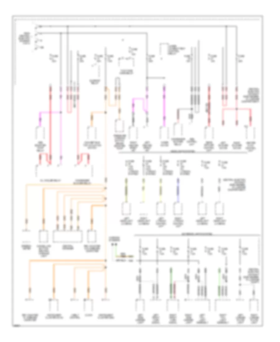
Power Distribution Wiring Diagram (4 of 4) for Porsche 911 Carrera 4 1995
List of elements for Power Distribution Wiring Diagram (4 of 4) for Porsche 911 Carrera 4 1995:
- (not rs
- (not used)
- (rs)
- 1/26
- 15e
- 2/26
- 2/3
- 2/7
- 2/8
- Abs booster pump
- Abs control unit
- B15
- B43
- C13
- C23
- C24
- C25
- C33
- C41
- C42
- Cancelling button, central warning light
- Central electric (on right side member, in luggage compartment)
- Central electric (on right side member, in luggage compt)
- Central informer
- Clock
- Condenser blower relay
- Condensor blower relay
- Convertible top actuation switch
- D22
- D33
- E13
- E14
- Exterior lights system
- F31
- F32
- F33
- F34
- F43
- From central electric (diagram 3 of 4)
- Fuse 15a
- Fuse 15a (w/ litronic system)
- Fuse 25a
- Fuse 30a
- Fuse 7.5a
- Fuse 7.5a (w/o litronic system)
- G13
- H23
- H24
- H25
- Headlights system
- Heater & a/c control unit
- Instrument cluster (d100)
- Instrument cluster (d80)
- J24
- K/2
- K12
- L13
- L31
- L32
- Left blower motor
- Left front turn signal
- Left headlight (lo beam)
- Left heated spray jet
- Left license plate light
- Left litronic control unit
- Left side marker light
- Left tail- light assembly
- M22
- M23
- M33
- M34
- N21
- Oil cooler relay
- Or turbo)
- Pressure warning switch, brake booster pump
- Rear spoiler control unit
- Red
- Relay
- Rev counter w/ onboard computer
- Rev counter w/o onboard computer
- Right blower motor
- Right front turn signal
- Right headlight (lo beam)
- Right heated spray jet
- Right license plate light
- Right litronic control unit
- Right side marker light
- Right tail- light assembly
- Speedo- meter
- Sunroof relay
- Two-tone horn relay
- V-belt control
- Warning systems
- Wiper intermittent control relay
- Wiper motor
POWER DOOR LOCKS
Power Door Lock Wiring Diagram for Porsche 911 Carrera 4 1995
List of elements for Power Door Lock Wiring Diagram for Porsche 911 Carrera 4 1995:
- (not used)
- Anti-drive off control unit (late production)
- Central alarm locking control unit (below right seat)
- Central electric (on right side member, in luggage compartment)
- Central lock button
- Central lock. button
- Driver's side driver motor
- Driver's side lock cylinder (early production)
- Early prod
- G105 (on right side member, in luggage compt)
- G202 (left side member)
- G405 (right rear of engine compt)
- Hot at all times
- L41
- Lamp button
- Late prod
- Limit switch close
- Limit switch open
- Lock
- Motor close
- Motor open
- On ind.
- Passenger's side drive motor
- Passenger's side lock cylinder (early production)
- Power
- Prime alarm system
- Rear package tray drive motor
- Revolution counter w/o on- board unit
- Solid state
- Unlock
- Unprime alarm system
POWER MIRRORS
Power Mirror Wiring Diagram, Early Production for Porsche 911 Carrera 4 1995
List of elements for Power Mirror Wiring Diagram, Early Production for Porsche 911 Carrera 4 1995:
- Central electric (right rear side luggage compartment)
- Driver's side mirror
- Fuse 15a
- G105 (on right side member, in luggage compartment)
- G202 (left side member)
- Hot in acc or run
- M1l
- M1r
- M2l
- M2r
- Passenger's side mirror
- Power mirror switch
- Rear window defogger switch
- Red
Power Mirror Wiring Diagram, Late Production for Porsche 911 Carrera 4 1995
List of elements for Power Mirror Wiring Diagram, Late Production for Porsche 911 Carrera 4 1995:
- (cabrio)
- (coupe)
- Central electric (right rear side luggage compartment)
- Driver's side mirror
- Fuse 15a
- G105 (on right side member, in luggage compartment)
- G202 (left side member)
- Hot in acc or run
- M1l
- M1r
- M2l
- M2r
- Mirror heater switch
- Passenger's side mirror
- Power mirror switch
- Rear window defogger control relay
- Red
POWER SEATS
Comfort Seats Wiring Diagram for Porsche 911 Carrera 4 1995
List of elements for Comfort Seats Wiring Diagram for Porsche 911 Carrera 4 1995:
- (left seat)
- (left seat) j13 k34
- (left seat) j32 j34
- (right seat)
- (right seat)
- 4-way seat switch 1
- 4-way seat switch 2
- 4-way seat switch 3
- Backrest heating element
- Central electric (right rear side of luggage compartment)
- Comfort seat
- Front seat cushion height control
- Fuse 25 25a
- Fuse 6 30a (right seat)
- Fuse 8 30a (left seat)
- G300 (below left front seat)
- G301 (below right front seat)
- Hot at all times
- Hot in acc or run
- Lumbar curve control
- Lumbar height control
- Rear seat cushion height control
- Red
- Seat back forward control
- Seat backrest control
- Seat cushion heating element
- Seat heater control unit
- Seat heater switch
- Side pad heating element
- Solid state
Sport Seats Wiring Diagram for Porsche 911 Carrera 4 1995
List of elements for Sport Seats Wiring Diagram for Porsche 911 Carrera 4 1995:
- (left seat)
- (left seat) j32 j34 red
- (right seat)
- (right seat)
- 2-way seat switch 1
- 2-way seat switch 2
- Backrest heating element
- Central electric (right rear side of luggage compartment)
- Front seat cushion height control
- Fuse 25 25a
- Fuse 6 30a (right seat)
- Fuse 8 30a (left seat)
- G300 (below left front seat)
- G301 (below right front seat)
- Hot at all times
- Hot in acc or run
- Rear seat cushion height control
- Red
- Seat cushion heating element
- Seat heater control unit
- Seat heater switch
- Side pad heating element
- Solid state
- Sport seat
POWER TOP/SUNROOF
Convertible Top Wiring Diagram for Porsche 911 Carrera 4 1995
List of elements for Convertible Top Wiring Diagram for Porsche 911 Carrera 4 1995:
- (cabrio)
- (left
- 1/1
- 1/4
- 2/14
- 2/19
- Acc
- B15
- Cabrio
- Cabrio ind.
- Central electric (on right side member, in luggage compartment)
- Central informer (on steering column)
- Convertible top control unit (left side of i/p)
- Convertible top opened microswitch (behind side panel covering, in engine compartment)
- Convertible top switch
- D13
- D32
- Early prod.
- Fuse 15a
- Fuse 30a
- Fuse 7.5a
- G105 (on right side member, in luggage compartment)
- G202 side member)
- G405 (right rear of engine compartment)
- Hot at all times
- Hot in run or start
- Ignition starter switch
- Instrument cluster (clock)
- K32 red
- L23
- L33
- Late prod.
- Left motor (behind left rear seat)
- Left motor top lock (left front of roof)
- Left roof microswitch (left front of roof)
- Limit sw
- Lock
- Nca
- Not used
- Oil pressure
- Oil pressure/ sensor switch (center front of engine)
- Parking brake
- Parking brake switch
- Power windows system (power window regulator relay)
- Right motor (behind right rear seat)
- Right motor top lock (right front of roof)
- Right roof microswitch (right front of roof)
- Run
- Start
- Sun roof relay
- Tdc microswitch (behind side panel covering, in engine compartment)
Sunroof Wiring Diagram for Porsche 911 Carrera 4 1995
List of elements for Sunroof Wiring Diagram for Porsche 911 Carrera 4 1995:
- (left
- Central electric (right rear side of luggage compartment)
- Fuse 13 30a
- G105 (on right side member, in luggage compartment)
- G202 side member)
- Hot at all times
- Power windows system (power window regulator relay)
- Sun roof relay
- Sunroof motor (center rear of roof)
- Sunroof switch
POWER WINDOWS
Power Window Wiring Diagram for Porsche 911 Carrera 4 1995
List of elements for Power Window Wiring Diagram for Porsche 911 Carrera 4 1995:
- Central electric (on right side member, in luggage compartment)
- Driver's side power window motor
- Driver's side power window switch
- Driver's side power window switch (for right window)
- Fuse 30a
- G105 (on right side member, in luggage compartment)
- G202 (left side member)
- Hot at all times
- Hot in acc or run
- K45
- L33
- Left door contact switch
- Passenger's side power window motor
- Passenger's side power window switch
- Power tops system (sun roof relay)
- Power window regulator relay
- Right door contact switch
- Solid state
RADIO
Radio Wiring Diagrams, with Amplifier for Porsche 911 Carrera 4 1995
List of elements for Radio Wiring Diagrams, with Amplifier for Porsche 911 Carrera 4 1995:
- Acc
- Amplifier
- Antenna
- Antenna amplifier
- Carrera
- Cd changer
- Central electric
- Central electric (on right side member, in luggage compartment)
- Clock
- D44
- D45
- Data
- Deep range
- Dsp processor (digital audio only)
- E15
- Fuse 15a
- G104 (battery, on left side of luggage compartment)
- G105 (on right side member)
- G202 (left side member)
- Ground
- High range
- Hot at all times
- Hot in acc or run
- Ignition starter switch
- K15
- Left front +
- Left front -
- Left front speakers
- Left front sub -
- Left rear +
- Left rear -
- Left rear speakers
- Lock
- M31
- M32
- Middle range
- Midrange
- Nca
- Radio
- Red
- Right front +
- Right front -
- Right front speakers
- Right front sub +
- Right front sub -
- Right rear +
- Right rear -
- Right rear speakers
- Run
- Speedometer
- Start
- Tel mute
- Telephone
- Term 30+
- Term 31+
- Term 31-
- Turbo
Radio Wiring Diagrams, without Amplifier for Porsche 911 Carrera 4 1995
List of elements for Radio Wiring Diagrams, without Amplifier for Porsche 911 Carrera 4 1995:
- Acc
- Antenna
- Antenna amplifier
- Carrera
- Cd changer
- Central electric
- Central electric (on right side member, in luggage compartment)
- D44
- Deep range
- E15
- Fl+
- Fl-
- Fr+
- Fr-
- Fuse 15a
- G104 (battery, on left side of luggage compartment)
- G105 (on right side member)
- High range
- Hot at all times
- Ignition starter switch
- Left door loud- speaker
- Left front speakers
- Left rear speaker
- Lock
- M31
- Nca
- Radio
- Red
- Right door loud- speaker
- Right front speakers
- Right rear speaker
- Rl+
- Rl-
- Rr+
- Rr-
- Run
- Start
- Tel mute
- Telephone
- Term 30+
- Term 31-
- Turbo
SHIFT INTERLOCKS
Shift Interlock Wiring Diagram, Early Production for Porsche 911 Carrera 4 1995
List of elements for Shift Interlock Wiring Diagram, Early Production for Porsche 911 Carrera 4 1995:
- Actuator
- B24
- Central electric (on right side member, in luggage compartment)
- Cruise control system (cruise control unit)
- Fuse 19 15a
- G105 (on right side member, in luggage compartment)
- G202 (left side member)
- Ground
- Hot in run or start
- Instrument cluster system (speedometer)
- Nca
- P/n lock control unit (central electric)
- P/n lock magnet
- P/n position
- Selector lever switch
- Speed sig
- Stop lamp switch (top of brake pedal support)
- Stop lights
- Term. 15
Shift Interlock Wiring Diagram, Late Production for Porsche 911 Carrera 4 1995
List of elements for Shift Interlock Wiring Diagram, Late Production for Porsche 911 Carrera 4 1995:
- Actuator
- B24
- Central electric (on right side member, in luggage compartment)
- Cruise control system (cruise control unit)
- Fuse 19 15a
- Fuse 27 15a
- G202 (left side member)
- G300 (below left front seat)
- Ground
- Hot in run or start
- Instrument cluster system (speedometer)
- Nca
- O12
- P/n lock control unit (central electric)
- P/n lock magnet
- P/n position
- Selector lever switch
- Speed sig
- Stop lamp switch (top of brake pedal support)
- Stop lights
- Term. 15
STARTING/CHARGING
Charging Wiring Diagram, Early Production for Porsche 911 Carrera 4 1995
List of elements for Charging Wiring Diagram, Early Production for Porsche 911 Carrera 4 1995:
- (clock)
- (right rear side luggage
- (under right seat)
- 1/2
- 2/23
- Abs control unit (right front luggage compt)
- Alarm system/ central locking control unit
- B15
- Battery
- Battery ind.
- Battery junction box
- Central electric
- Central electric (right rear side luggage
- Central informer (left side firewall)
- Compt)
- Fuse 7.5a
- G104 (battery, on left side of luggage compartment)
- G133 (on crankcase)
- Generator
- Hot in run
- Instrument cluster
- M12
- N42
- Nca
- Or start
- Power distribution system
- Red
- Starter
- Suppressor capacitor
Charging Wiring Diagram, Late Production for Porsche 911 Carrera 4 1995
List of elements for Charging Wiring Diagram, Late Production for Porsche 911 Carrera 4 1995:
- (clock)
- (except rs) (under right seat)
- (right rear side luggage
- 1/2
- 2/23
- Abs control unit (right front luggage compt)
- Alarm system/ central locking control unit
- B15
- Battery
- Battery junction box
- Battery main switch
- Central electric
- Central electric (right rear side luggage
- Central informer (left side firewall)
- Charge ind.
- Compt)
- Except rs
- Fuse 7.5a
- G104 (battery, on left side of luggage compartment)
- G133 (camshaft casing, cyl 3)
- Generator
- Hot in run
- Instrument cluster
- M12
- N42
- Nca
- Or start
- Power distribution system
- Red
- Starter
- Suppressor capacitor
Starting Wiring Diagram, Early Production for Porsche 911 Carrera 4 1995
List of elements for Starting Wiring Diagram, Early Production for Porsche 911 Carrera 4 1995:
- (below
- Acc
- Battery
- Battery junction box
- Central electric (right rear side luggage compartment)
- Code lock
- G104 (battery, on left side of luggage compartment)
- G105 (on right side member in, luggage compt)
- G300 (below left front seat)
- G403 (right side eng compt)
- Generator
- Ignition starter switch
- Left seat)
- Lifting switch (on gearbox)
- M249
- M249 & m530
- M249-a/t (tiptronic) m480-m/t m530-code lock
- M480
- M530
- Mfi + di control
- Nca
- Off
- Power distribution system
- Red
- Start
- Start relay
- Starter
- Stepped switch
- Unit
Starting Wiring Diagram, Late Production for Porsche 911 Carrera 4 1995
List of elements for Starting Wiring Diagram, Late Production for Porsche 911 Carrera 4 1995:
- (below
- (on right side member, in luggage compt)
- Acc
- Anti-drive-off control unit
- Battery
- Battery junction box
- Battery main switch
- Central electric (right rear side luggage compartment)
- Except rs
- G104 (battery, on left side of luggage compartment)
- G105
- G300 (below left seat)
- G403 (right side eng compt)
- Generator
- Ignition starter switch
- Left seat)
- Lifting switch (on gearbox)
- M249
- M249 & m530
- M249-a/t (tiptronic) m480-m/t m530-code lock
- M480
- M530
- Mfi + di control
- Nca
- Off
- Power distribution system
- Red
- Start
- Start relay
- Start relay +
- Starter
- Stepped switch
- Unit
SUPPLEMENTAL RESTRAINTS
Supplemental Restraint Wiring Diagram, Early Production for Porsche 911 Carrera 4 1995
List of elements for Supplemental Restraint Wiring Diagram, Early Production for Porsche 911 Carrera 4 1995:
- 1/15
- 1/6
- 1/9
- 2/16
- Airbag
- Airbag control unit (center of i/p)
- Airbag ind.
- B15
- Central alarm locking control unit (below right front seat)
- Central electric (right rear side luggage compartment)
- Central informer (on steering column)
- Code lock
- Contact unit (top of steering column)
- Diagnosis plug socket (passenger's footwell)
- Driver ignition tablet
- Driver's airbag (top of steering column)
- Fuse 7.5a
- G202 (left side member)
- Hazard light airbag
- Hot in run or start
- Instrument cluster (clock)
- K lead
- K14
- Mfi term 15
- Nca
- Pass. ignition tablet
- Passenger's airbag (right side of i/p)
- Pnk
- Term 15
- Term 31
Supplemental Restraint Wiring Diagram, Late Production for Porsche 911 Carrera 4 1995
List of elements for Supplemental Restraint Wiring Diagram, Late Production for Porsche 911 Carrera 4 1995:
- 1/15
- 1/6
- 1/9
- 2/16
- Airbag
- Airbag control unit (center of i/p)
- Airbag ind.
- B15
- C32
- Central alarm locking control unit (below right front seat)
- Central electric (right rear side luggage compartment)
- Central informer (on steering column)
- Contact unit (top of steering column)
- Diagnosis plug socket (passenger's footwell)
- Driver ignition tablet
- Driver's airbag (top of steering column)
- Except rs
- Fuse 7.5a
- G202 (left side member)
- H14
- Hazard light airbag
- Hot in run or start
- Instrument cluster (clock)
- J44
- K lead
- K14
- Main battery switch
- Mfi term 15
- Nca
- Pass. ignition tablet
- Passenger's airbag (right side of i/p)
- Pnk
- Rs (m002)
- Rs (m003)
- Term 15
- Term 31
TRANSMISSION
Transmission Wiring Diagram (1 of 2) for Porsche 911 Carrera 4 1995
List of elements for Transmission Wiring Diagram (1 of 2) for Porsche 911 Carrera 4 1995:
- 5v out
- 5v ref
- Abs control unit (right front luggage compt)
- All times
- Backup light relay
- Backup rly
- Central electric (right rear luggage compt.)
- Change dn
- Change up
- Coding
- Converter lockup clutch solenoid valve
- Cooler blwr
- D12
- Diagnosis plug socket (passenger's footwell)
- Dme control unit (below left front seat)
- Drive speed
- Drive speed induction pulse sensor
- Dspl 1st gr
- Dspl 2nd gr
- Dspl 3rd gr
- Dspl 4th gr
- Dspl man op
- F23
- Fr wheel sp
- Fuse 15a
- Fuse 7.5a
- G300 (below left front seat)
- Grd
- Hot at
- Hot in on or start
- Ign adj
- K lead
- Kickdown sw
- L lead
- Lamp ctrl
- Lat accel
- Lateral acceleration sensor (in center console)
- Load sig
- Mfi+di relay
- Mfi+di rly
- Mod press
- Modu- lation press. solenoid valve
- Oil cooler relay
- Pin code 1
- Pin code 2
- Plug
- Prog sig m
- Red
- Redundacy r
- Screen
- Shield
- Shift vlv 1
- Shift vlv 2
- Socket
- Sol vlv +
- Stop lt sw
- Sw pos x
- Sw pos y
- Sw pos z
- Switching point control solenoid valve 1
- Switching point control solenoid valve 2
- Tcc ctrl
- Term. 15
- Term. 30
- Throttle valve potentiometer (on throttle valve assembly)
- Throttle vlv
- Trans temp
- Trans- mission temp. sensor
- Transmission control unit (below left front seat)
- Transmission electronics
Transmission Wiring Diagram (2 of 2) for Porsche 911 Carrera 4 1995
List of elements for Transmission Wiring Diagram (2 of 2) for Porsche 911 Carrera 4 1995:
- (right side member)
- 1/2
- 1/3
- 1st gear display
- 2nd gear display
- 3rd gear display
- 4th gear display
- A/t ind.
- Buzzer contact
- Central electric (right rear luggage compt.)
- Cruise control system
- Fuse 15a
- G105
- G202 (behind left i/p)
- G300 (below left front seat)
- Grd
- Ground
- Hot in on or start
- Instrument cluster
- Instrument cluster (prndl display)
- Interior lights system
- Kick- down switch (below accel- erator)
- Lkng slnd actr
- Load consum- ption
- M15
- Manual oper display
- Nca
- P/n lock mag- net
- P/n pstn
- S1- man. shft
- S2- chng up
- S3- chng down
- S4- park pstn
- Selector lever lock control unit (in central electric)
- Selector lever switch
- Speed sgnl
- Starter relay
- Stop light switch
- Stop lt sw
- Switch lifting (on gearbox)
- Switch position x
- Switch position y
- Switch position z
- Te 58
- Te 58d
- Term
- Vss
- Warnings system
Transmission Wiring Diagram, Early Production (1 of 2) for Porsche 911 Carrera 4 1995
List of elements for Transmission Wiring Diagram, Early Production (1 of 2) for Porsche 911 Carrera 4 1995:
- 5v out
- 5v ref
- Abs control unit (right front luggage compt)
- All times
- Backup rly
- Central electric (right rear luggage compt.)
- Change dn
- Change up
- Coding
- Converter lockup clutch solenoid valve
- D12
- Diagnosis plug socket (passenger's footwell)
- Drive speed
- Drive speed induction pulse sensor
- Dspl 1st gr
- Dspl 2nd gr
- Dspl 3rd gr
- Dspl 4th gr
- Dspl man op
- Engine spd
- Exterior lights system
- Fr wheel sp
- Fuse 15a
- G300 (below left front seat)
- Grd
- Hot at
- Hot in on or start
- Ign adj
- K lead
- K32
- Kickdown sw
- L lead
- Lamp ctrl
- Lat accel
- Lateral acceleration sensor (in center console)
- Load sig
- Mf+di control unit (below left front seat)
- Mod press
- Modu- lation press. solenoid valve
- Pin code 1
- Pin code 2
- Plug
- Pnk/
- Prog sig m
- Red
- Redundacy r
- Screen
- Shield
- Shift vlv 1
- Shift vlv 2
- Socket
- Sol vlv +
- Stop lt sw
- Sw pos x
- Sw pos y
- Sw pos z
- Switching point control solenoid valve 1
- Switching point control solenoid valve 2
- Tcc ctrl
- Term. 15
- Term. 30
- Trans temp
- Trans- mission temp. sensor
- Transmission control unit (below left front seat)
- Transmission electronics
- Tv-sig
Transmission Wiring Diagram, Early Production (2 of 2) for Porsche 911 Carrera 4 1995
List of elements for Transmission Wiring Diagram, Early Production (2 of 2) for Porsche 911 Carrera 4 1995:
- (right side member)
- 1st gear display
- 2/5
- 2nd gear display
- 3rd gear display
- 4th gear display
- B24
- Buzzer contact
- Central electric (right rear luggage compt.)
- Cruise control system
- Fuse 15a
- G105
- G129 (on transmission)
- G202 (left side member)
- G300 (below left front seat)
- Grd
- Ground
- Hot in on or start
- Instrument cluster
- Instrument cluster (prndl display)
- Interior lights system
- Kick- down switch (below accel- erator)
- Lkng slnd actr
- Load consum- ption
- Manual oper display
- Nca
- P/n lock control unit (in central electric)
- P/n lock mag- net
- P/n pstn
- S1- man. shft
- S2- chng up
- S3- chng down
- S4- park pstn
- Selector lever switch
- Stop light switch
- Stop lt sw
- Switch lifting (on gearbox)
- Switch position x
- Switch position y
- Switch position z
- Te 58
- Te 58d
- Term
- Tip- tronic
- Vss
- Warnings system
Transmission Wiring Diagram, Late Production (1 of 2) for Porsche 911 Carrera 4 1995
List of elements for Transmission Wiring Diagram, Late Production (1 of 2) for Porsche 911 Carrera 4 1995:
- (below left front seat)
- 5v out
- 5v ref
- Abs control unit (right front luggage compt)
- All times
- Backup rly
- Central electric (right rear luggage compt.)
- Change dn
- Change up
- Coding
- Converter lockup clutch solenoid valve
- D12
- Diagnosis plug socket (passenger's footwell)
- Drive speed
- Drive speed induction pulse sensor
- Dspl 1st gr
- Dspl 2nd gr
- Dspl 3rd gr
- Dspl 4th gr
- Dspl man op
- Engine spd
- Exterior lights system
- Fr wheel sp
- Fuse 15a
- G300
- Grd
- Hot at
- Hot in on or start
- Ign adj
- K lead
- K32
- Kickdown sw
- L lead
- Lamp ctrl
- Lat accel
- Lateral acceleration sensor (in center console)
- Load sig
- Mf+di control unit (below left front seat)
- Mod press
- Modu- lation press. solenoid valve
- Pin code 1
- Pin code 2
- Plug
- Pnk/
- Prog sig m
- Red
- Redundacy r
- Screen
- Shield
- Shift vlv 1
- Shift vlv 2
- Socket
- Sol vlv +
- Stop lt sw
- Sw pos x
- Sw pos y
- Sw pos z
- Switching point control solenoid valve 1
- Switching point control solenoid valve 2
- Tcc ctrl
- Term. 15
- Term. 30
- Trans temp
- Trans- mission temp. sensor
- Transmission control unit (below left front seat)
- Transmission electronics
- Tv-sig
Transmission Wiring Diagram, Late Production (2 of 2) for Porsche 911 Carrera 4 1995
List of elements for Transmission Wiring Diagram, Late Production (2 of 2) for Porsche 911 Carrera 4 1995:
- (right side member)
- 1st gear display
- 2/5
- 2nd gear display
- 3rd gear display
- 4th gear display
- B24
- Buzzer contact
- Central electric (right rear luggage compt.)
- Cruise control system
- Fuse 15a
- G105
- G129 (on transmission)
- G202 (left side member)
- G300 (below left front seat)
- Grd
- Ground
- Horn switch
- Hot in on or start
- Instrument cluster
- Instrument cluster (prndl display)
- Interior lights system
- Kick- down switch (below accel- erator)
- Lkng slnd actr
- Load consum- ption
- Manual oper display
- Nca
- P/n lock control unit (in central electric)
- P/n lock mag- net
- P/n pstn
- S1- man. shft
- S2- chng up
- S3- chng down
- S4- park pstn
- Selector lever switch
- Steering wheel contact unit
- Stop light switch
- Stop lt sw
- Switch lifting (on gearbox)
- Switch position x
- Switch position y
- Switch position z
- Te 58
- Te 58d
- Term
- Tip- tronic
- Tiptronic steering wheel switch
- Vss
- Warnings system
WARNING SYSTEMS
Warning System Wiring Diagrams for Porsche 911 Carrera 4 1995
List of elements for Warning System Wiring Diagrams for Porsche 911 Carrera 4 1995:
- 1/14
- 1/15
- 58l
- 58r
- Acc
- B15
- Central electric (right rear side luggage compartment)
- Exterior lights system
- Fuse 7.5a
- G202 (left side member)
- G300 (below left front seat)
- Gong relay (left side of steering column)
- Hot at all times
- Hot in run or start
- Ignition lock buzzer contact (on ignition lock)
- Ignition starter switch
- Instrument cluster (clock)
- K44
- Left door contact switch
- Lock
- Red
- Right door contact switch
- Run
- Safety belt switch
- Seat belt ind
- Start
WIPER/WASHER
Wiper/Washer Wiring Diagram for Porsche 911 Carrera 4 1995
List of elements for Wiper/Washer Wiring Diagram for Porsche 911 Carrera 4 1995:
- (left front
- (right side of
- 31b
- 53a
- 53b
- 53c
- 53e
- 53i
- 53m
- 53s
- Central electric (on right side member, in luggage compartment)
- D32
- Early prod
- Fuse 15a
- Fuse 25a
- G100 (in luggage compartment, left front wheelwell)
- G105 (on right side member, in luggage compt)
- G202 (left side member)
- G405 (right rear of engine compartment)
- Headlight washer fluid pump (left front wheelwell)
- Headlight washer relay
- Headlights system
- Hot at all times
- Hot in acc or run
- Iii
- Inter- mittent wiper control relay
- Interval
- K25
- K32
- L31
- L32
- L43
- Late prod
- Left heated jet spray
- M21
- M24
- M25
- M35
- M43
- M44
- N14
- N25
- O44
- Off
- Potentiometer
- Rear window wiper motor
- Rear window wiper relay (on rear window wiper motor)
- Rear window wiper switch
- Red
- Right heated spray jet
- Solid state
- Tip sw
- Washing
- Windshield washer fluid pump (ex. rs) wheelwell) (rs) luggage compt)
- Wipe/ wash
- Wipe/wash
- Wipe/wash switch
- Wiper motor

 Čeština
 Dansk
Dansk Deutsch
 Ελληνικά
 English
 English
 Español
 Suomi
Suomi Français
 Français
 עברית
עברית Hrvatski
 Magyar
 Italiano
 日本語
日本語 한국어
한국어 Nederlands
 Polski
 Português
 Português
 Română
 Русский
 Slovenščina
 Svenska
 Türkçe
 中文 (中国)