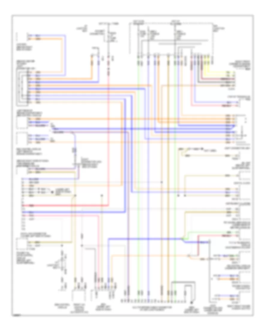
COMPUTER DATA LINES
Computer Data Lines Wiring Diagram for Hyundai Veracruz Limited 2007
List of elements for Computer Data Lines Wiring Diagram for Hyundai Veracruz Limited 2007:
- (behind center of dash) joint connector jm01
- (behind right side of dash) tire pressure monitoring module
- (left rear of engine compartment) abs control module
- (not used)
- (right front corner of engine compartment) ecm
- (top of transaxle) tcm
- (under left side of dash) gm01
- 4wd ecm (behind right end of dash)
- A05-a
- Abs 1 fusible link 40a
- Abs 2 fusible link 40a
- Bcm (under left side of dash)
- Can hi
- Can lo
- Clg-a
- D03-b
- D14-b
- Data link connector (lower left end of dash)
- Diag fuse 10a
- Digital clock
- E/r junction box
- E/r-clg
- E/r-frtb
- Esc control module (left rear of engine compartment)
- F06-b
- F19-b
- F53-a
- Front a/c control module (automatic a/c)
- Ge02 (under left end of dash)
- Hot at all times
- Hot in on or start
- I/p junction box
- I/p-h
- I/p-j
- I/p-m
- Ims control module (under driver's seat)
- Instrument cluster
- Jbl amp (behind left quarterpanel)
- Joint connector je01
- Joint connector jf02 (under center console)
- Joint connector jm03 (behind right end of dash)
- K line
- M01-b
- M04-b
- M04-c
- M05-a
- M05-b
- Multipurpose check connector (at e/r junction box)
- Nca
- Pic immobilizer module (under rear of center console)
- Pnk
- Power connector
- Power tail gate control module (behind left quarterpanel)
- Power window main switch
- Red
- Right front power window switch
- Room lp fuse 15a
- S38-c
- Srs control module
- Tilt & telescopic module (on steering column)
- W/ abs
- W/ esc
 Čeština
 Dansk
Dansk Deutsch
 Ελληνικά
 English
 English
 Español
 Suomi
Suomi Français
 Français
 עברית
עברית Hrvatski
 Magyar
 Italiano
 日本語
日本語 한국어
한국어 Nederlands
 Polski
 Português
 Português
 Română
 Русский
 Slovenčina
 Svenska
 Türkçe
 中文 (中国)
 Slovenščina