CRUISE CONTROL
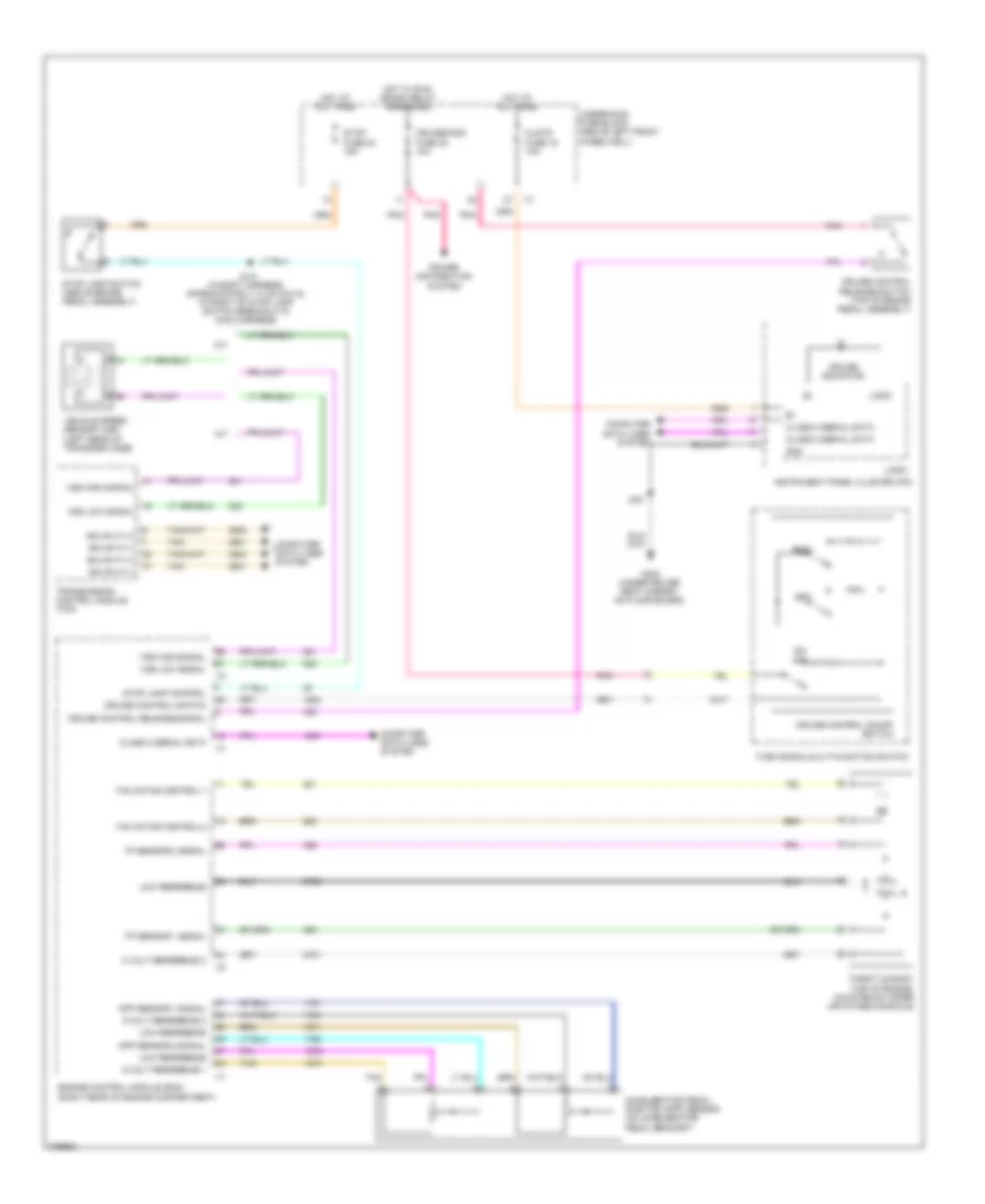
Cruise Control Wiring Diagram for Hummer H3 2008
List of elements for Cruise Control Wiring Diagram for Hummer H3 2008:
- 5 volt reference 2
- 5-volt reference 1
- 5-volt reference 2
- A/t
- Accelerator pedal position (app) sensor (on accelerator pedal bracket)
- App sensor 1 signal
- App sensor 2 signal
- Class 2 serial data
- Clstr fuse 19 10a
- Computer data lines system
- Cruise control on/off switch
- Cruise control release signal
- Cruise control release switch (top of brake pedal assembly)
- Cruise control switch
- Cruise indicator
- Cruise/misc fuse 35 10a
- Engine control module (ecm) (right rear of engine compartment)
- G300 (under driver seat carpet, on floor board)
- Gmlan hi (+)
- Gmlan hi (-)
- Gnd
- Hot at all times
- Hot w/ run/ crank relay energized
- Instrument panel cluster (ipc)
- J215 (in body harness, approximately 14 cm (5.5 in) to right of stop lamp switch breakout in main harness)
- J251
- Logic
- Low reference
- M/t
- Off
- On/
- Pnk
- Power distribution system
- Res+
- Set-
- Stop fuse 54 15a
- Stop lamp control
- Stop lamp switch (above brake pedal assembly)
- Tac motor control-1
- Tac motor control-2
- Tan
- Throttle body (top of engine, mounted on upper air intake manifold)
- Tp sensor 1 signal
- Tp sensor 2 signal
- Transmission control module (tcm)
- Turn signal/multi-function switch
- Underhood fuse block (above left front wheelwell)
- Vehicle speed sensor (vss) (left rear of transfer case)
- Vss high signal
- Vss low signal
 Čeština
 Dansk
Dansk Deutsch
 Ελληνικά
 English
 English
 Español
 Suomi
Suomi Français
 Français
 עברית
עברית Hrvatski
 Magyar
 Italiano
 日本語
日本語 한국어
한국어 Nederlands
 Polski
 Português
 Português
 Română
 Русский
 Slovenčina
 Svenska
 Türkçe
 中文 (中国)
 Slovenščina