CRUISE CONTROL
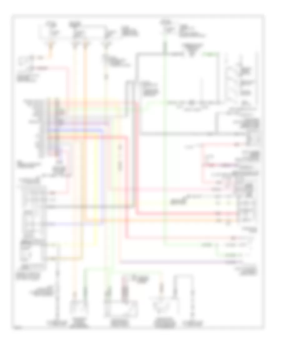
Cruise Control Wiring Diagram for Infiniti I35 2004
List of elements for Cruise Control Wiring Diagram for Infiniti I35 2004:
- (steering switch) combination switch
- (w/ tcs)
- (w/ vdc)
- 1l m19
- Abs/tcs control unit (at left rear corner of engine compt)
- Ascd brake switch (on brake pedal bracket)
- Ascd steering switch
- Ascd sw
- Avcc
- Brake nc sw
- Brake sw
- Can h
- Can l
- Cancel switch
- Close
- Combination
- Computer data lines system
- Cruise ind
- Cruise lamp (out)
- E83
- Ecm (behind instrument lower cover)
- Electric throttle control actuator (on throttle body)
- F39 (at front of left cylinder head)
- F41 (at front of left cylinder head)
- Fuse & fusible link box (at left side of engine compartment)
- Fuse 2 15a
- Fuse 20 15a
- Fuse 30 10a
- Fuse 63 15a
- Fuse block (j/b) (behind left side of dash)
- Gnd a
- Ground
- Hot at all times
- Hot in on or start
- Joint connector (lower left side of dash, near ecm)
- Joint connector 18 (lower left side of dash, near ecm)
- Joint connector 8 (in fuse & fusible link box)
- M17
- M214
- M216
- M25 (behind left side of dash)
- M32
- M33
- M34
- M644
- Main switch
- Meter
- Meter out
- Motor 1
- Motor 2
- Motor rly
- Nca
- Open
- Park/neutral position relay (in relay box 2)
- Park/neutral position switch (on left rear side of transaxle)
- Red
- Resume/ accel switch
- Sensor 1
- Sensor 2
- Set ind
- Set lamp (out)
- Set/coast switch
- Spiral cable
- Starting/ charging system
- Stop lamp switch (on brake pedal bracket)
- Throttle control motor
- Throttle control motor relay (in relay box 2)
- Throttle position sensor
- Tps1
- Tps2
- Transmission control module (tcm) (behind lower center of dash)
- Unified meter ctrl unit (w/ odo/ trip meter
- Vehicle speed sensor (at top right rear of transaxle)
- Vmot
- Vsp
- W/ tcs
- W/ vdc
 Čeština
 Dansk
Dansk Deutsch
 Ελληνικά
 English
 English
 Español
 Suomi
Suomi Français
 Français
 עברית
עברית Hrvatski
 Magyar
 Italiano
 日本語
日本語 한국어
한국어 Nederlands
 Polski
 Português
 Português
 Română
 Русский
 Slovenčina
 Svenska
 Türkçe
 中文 (中国)
 Slovenščina