COOLING FAN
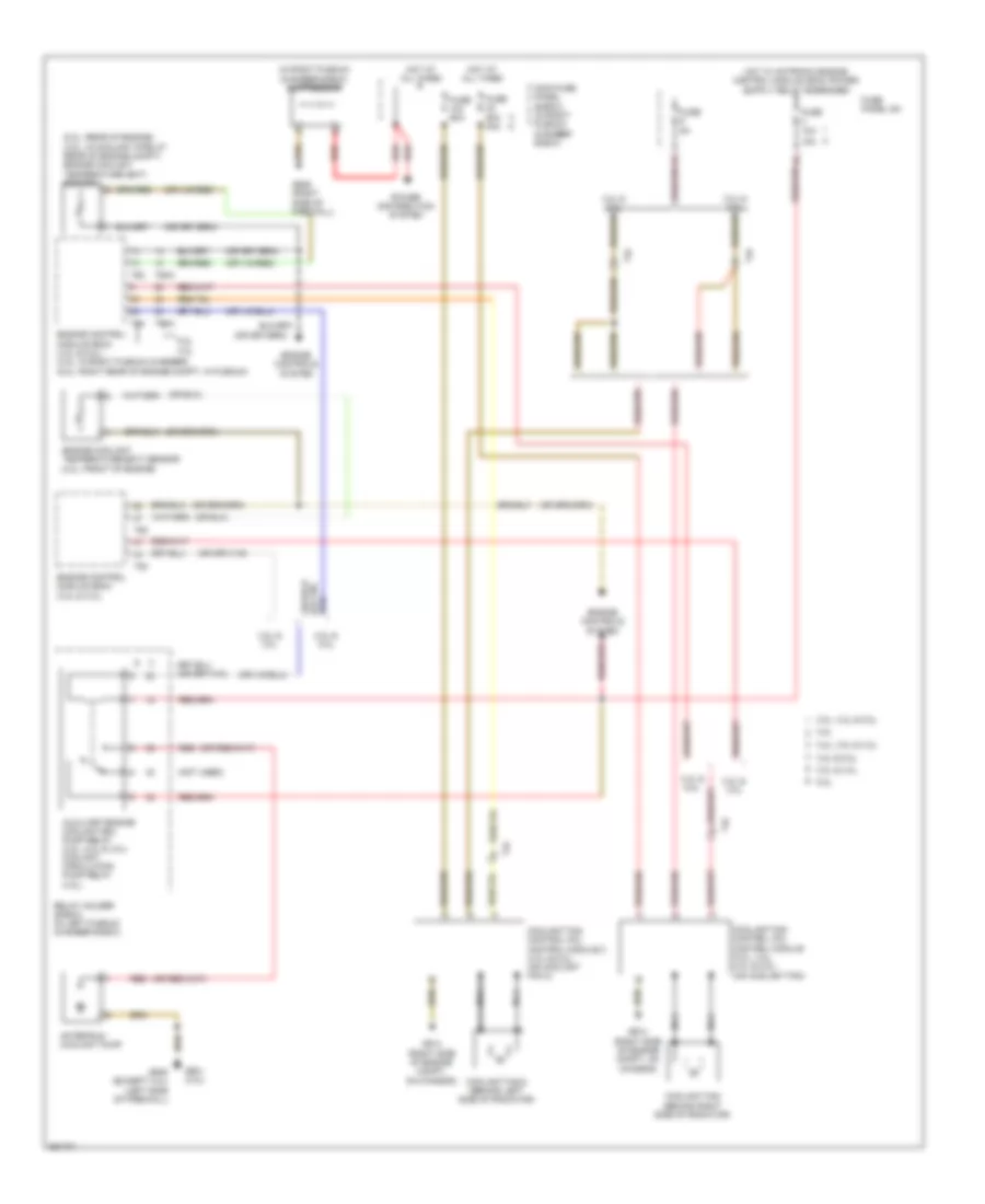
Cooling Fan Wiring Diagram for Audi A6 4.2 Quattro 2011
List of elements for Cooling Fan Wiring Diagram for Audi A6 4.2 Quattro 2011:
- (5.2l: rear of engine) (4.2l: in coolant pipe at rear of engine compt) engine coolant temperature (ect) sensor
- (in right plenum chamber e-box) suppressor
- (not used)
- 15a
- 3.0l & 3.2l
- 3.0l, 4.2l & 5.2l
- 3.2l
- 3.2l & 3.0l
- 3.2l, 3.0l & 4.2l
- 4.2l & 5.2l
- 5.2l
- 5.2l 4.2l
- After-run coolant pump
- Auxiliary engine coolant (ec) pump relay (3.2l, 5.2l & 3.0l) coolant circulation pump relay (4.2l)
- Coolant fan (behind right side of radiator)
- Coolant fan 2 (behind left side of radiator)
- Coolant fan control (fc) control module (3.0l, 3.2l, 4.2l & 5.2l) (on coolant fan)
- Coolant fan control (fc) control module 2 (4.2l & 5.2l) (on coolant fan 2)
- Engine control module (ecm) (3.2l & 3.0l)
- Engine control module (ecm) (4.2l & 5.2l) (4.2l: in right plenum chamber) (5.2l: right rear of engine compt, in plenum)
- Engine controls system
- Engine coolant temperature (ect) sensor (3.2l: front of engine)
- Fuse 10a
- Fuse 5a
- Fuse 60a
- Fuse 60a 40a
- Fuse panel sa
- G601 (3.0l)
- G614 (right side of engine compt, on chassis)
- G645 (except 3.0l) (left side of firewall)
- G646 (right side of firewall)
- Hot at all times
- Main fuse panel (e-box) (in right plenum chamber e-box)
- Nca
- Power distribution system
- Red
- Relay holder (e-box) (in left plenum chamber e-box)
- T4c
- T60
- T60a
- T94
- T94a
 Čeština
 Dansk
Dansk Deutsch
 Ελληνικά
 English
 English
 Español
 Suomi
Suomi Français
 Français
 עברית
עברית Hrvatski
 Magyar
 Italiano
 日本語
日本語 한국어
한국어 Nederlands
 Polski
 Português
 Português
 Română
 Русский
 Slovenčina
 Svenska
 Türkçe
 中文 (中国)
 Slovenščina