
 Čeština
 Dansk
Dansk Deutsch
 Ελληνικά
 English
 English
 Español
 Suomi
Suomi Français
 Français
 עברית
עברית Hrvatski
 Magyar
 Italiano
 日本語
日本語 한국어
한국어 Nederlands
 Polski
 Português
 Português
 Română
 Русский
 Slovenčina
 Svenska
 Türkçe
 中文 (中国)

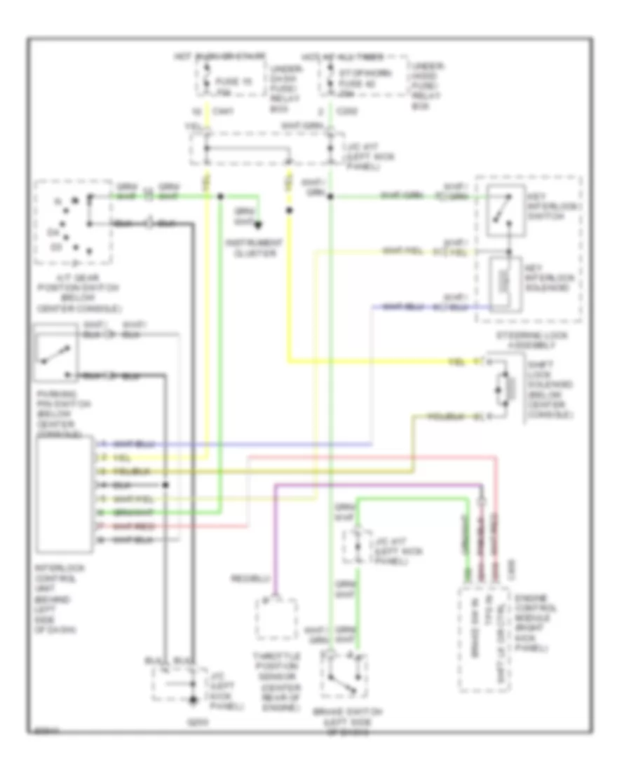
SHIFT INTERLOCKS
Shift Interlock Wiring Diagram for Honda Civic Si 1995
List of elements for Shift Interlock Wiring Diagram for Honda Civic Si 1995:

AIR CONDITIONINGANTI-LOCK BRAKESANTI-THEFTENGINE PERFORMANCECRUISE CONTROLEXTERIOR LIGHTSDEFOGGERSGROUND DISTRIBUTIONCOMPUTER DATA LINESHEADLIGHTSCOOLING FANINSTRUMENT CLUSTERHORNPOWER DOOR LOCKSPOWER DISTRIBUTIONPOWER MIRRORSINTERIOR LIGHTSPOWER WINDOWSRADIOPOWER TOP/SUNROOFSUPPLEMENTAL RESTRAINTSSHIFT INTERLOCKSSTARTING/CHARGINGWARNING SYSTEMSTRANSMISSIONWIPER/WASHER