INSTRUMENT CLUSTER
Instrument Cluster Wiring Diagram for MINI Cooper 2007
 https://portal-diagnostov.com/license.html
Automotive Electricians Portal FZCO
Automotive Electricians Portal FZCO
https://portal-diagnostov.com/license.html
https://portal-diagnostov.com/license.html
Automotive Electricians Portal FZCO
Automotive Electricians Portal FZCO
List of elements for Instrument Cluster Wiring Diagram for MINI Cooper 2007:
- (left door) (coupe) (under left rear seat) (convertible) x13230
- Auxiliary instrument cluster
- Brake ind
- Brake pad wear ind
- Charge ind lamp
- Computer data lines system
- Digital clock
- Electric fuel pump
- Exterior lights system
- Exterior lights systems
- Fuel level sensor 1
- Fuel level sensor 2
- Fuse fuse f21 10a
- Fuse fuse f3 5a
- Fuse fuse f5 5a
- Fuse fuse f9 5a
- Fuse holder 2 (behind left footwell trim)
- General module control unit
- Hand brake switch
- Hot at all times
- Hot in accy, run and start
- Hot in start
- Instrument cluster module
- Interior lights system
- Left front brake pad sensor
- Oil pressure ind
- Oil pressure switch
- Outside temperature sensor
- Right rear brake pad sensor
- Starting/charging system
- X10200
- X10202
- X10206
- X11175
- X11177
- X255
- X494 (right rear side of luggage compt)
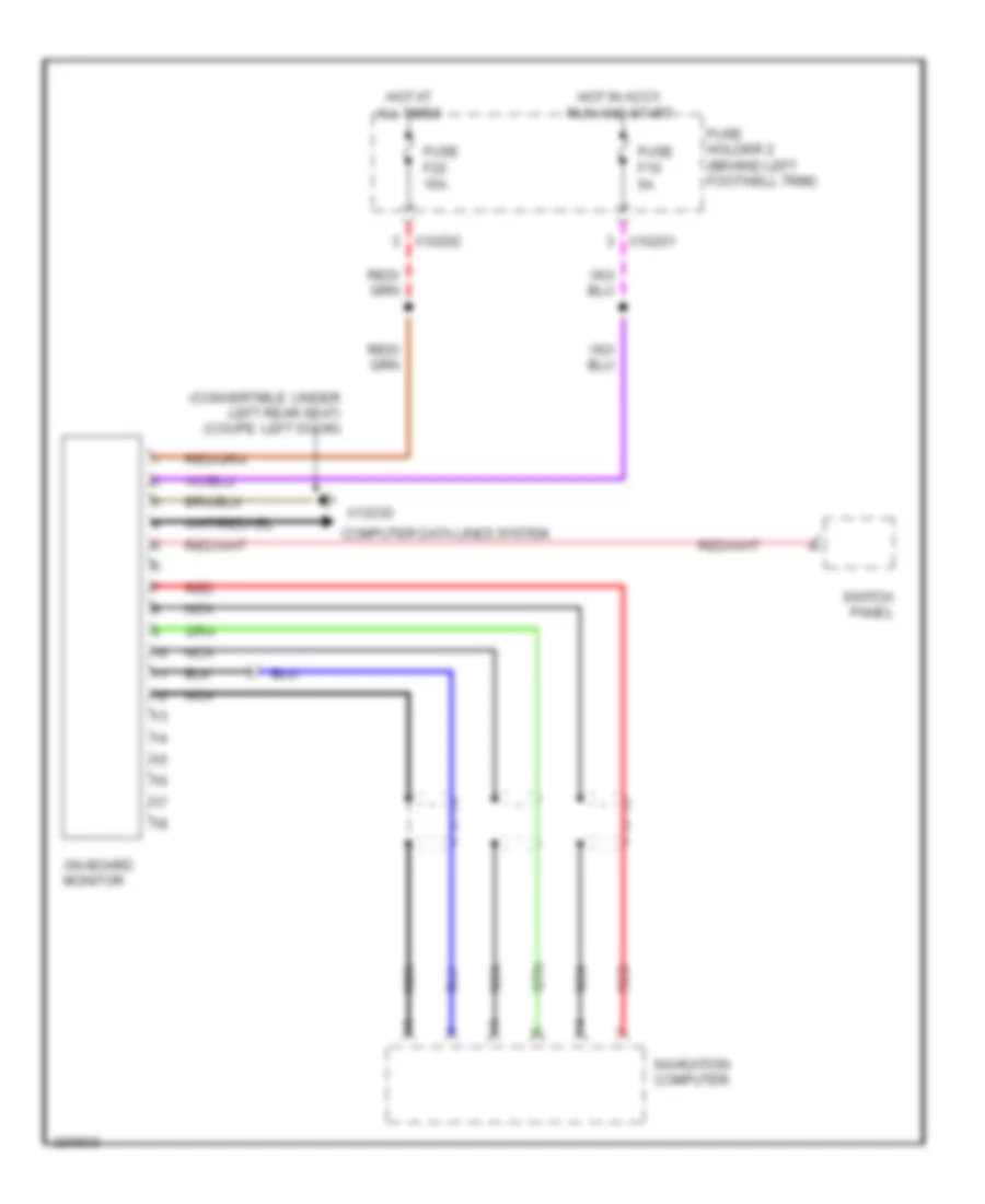
On-Board Computer Wiring Diagram for MINI Cooper 2007
List of elements for On-Board Computer Wiring Diagram for MINI Cooper 2007:
- (convertible: under left rear seat) (coupe: left door)
- Computer data lines system
- Fuse f10 5a
- Fuse f22 15a
- Fuse holder 2 (behind left footwell trim)
- Hot at all times
- Hot in accy, run and start
- Navigation computer
- Nca
- On-board monitor
- Red
- Switch panel
- X10201
- X10202
- X13230

 Čeština
 Dansk
Dansk Deutsch
 Ελληνικά
 English
 English
 Español
 Suomi
Suomi Français
 Français
 עברית
עברית Hrvatski
 Magyar
 Italiano
 日本語
日本語 한국어
한국어 Nederlands
 Polski
 Português
 Português
 Română
 Русский
 Slovenčina
 Svenska
 Türkçe
 中文 (中国)