TRANSMISSION
2.5L
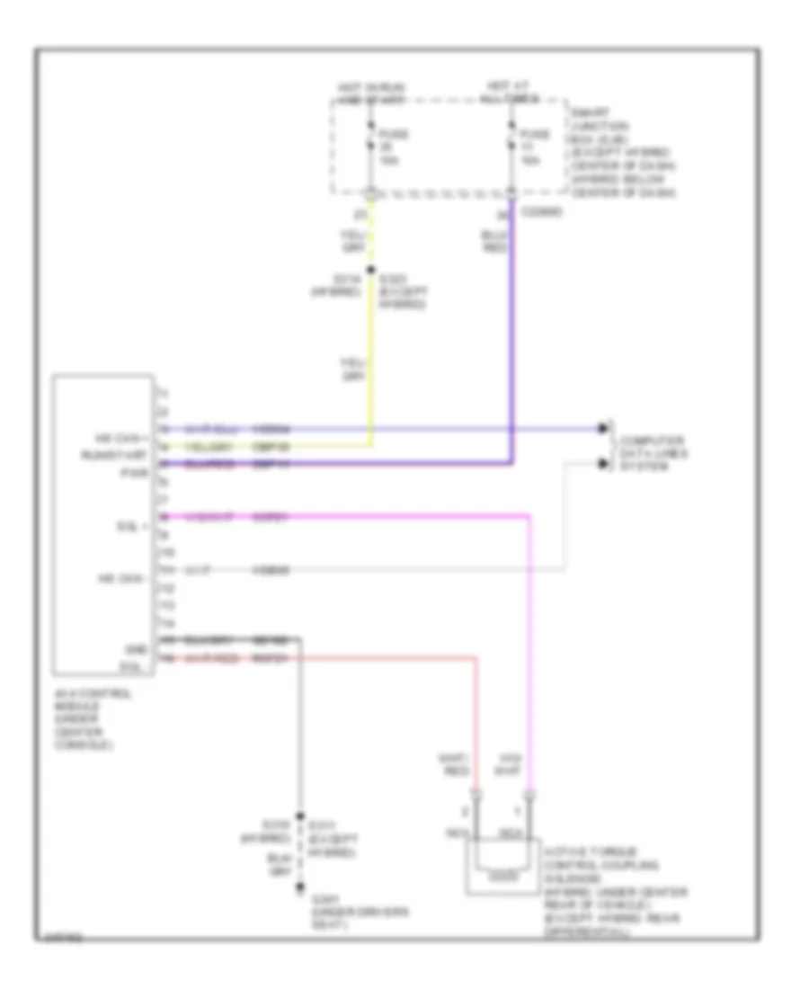
2.5L, 4WD Wiring Diagram for Ford Escape 2011
 https://portal-diagnostov.com/license.html
Automotive Electricians Portal FZCO
Automotive Electricians Portal FZCO
https://portal-diagnostov.com/license.html
https://portal-diagnostov.com/license.html
Automotive Electricians Portal FZCO
Automotive Electricians Portal FZCO
List of elements for 2.5L, 4WD Wiring Diagram for Ford Escape 2011:
- 4x4 control module (under center console)
- Active torque control coupling solenoid (hybrid: under center rear of vehicle) (except hybrid: rear differential)
- C2280d
- Cbp35
- Ccf21
- Computer data lines system
- Fuse 10a
- G301 (under driver's seat)
- Gd182
- Gnd
- Hot at all times
- Hot in run and start
- Hs can +
- Hs can -
- Nca
- Pwr
- Rcf21
- Run/start
- S310 (hybrid)
- S311 (except hybrid)
- S314 (hybrid)
- S323 (except hybrid)
- Sbp11
- Smart junction box (sjb) (except hybrid: center of dash) (hybrid: below center of dash)
- Sol +
- Sol -
- Vdb04
- Vdb05
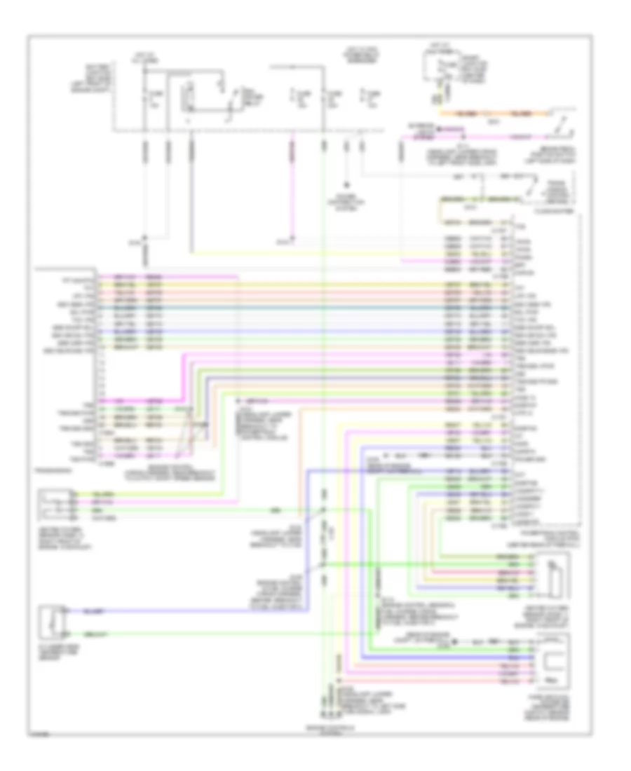
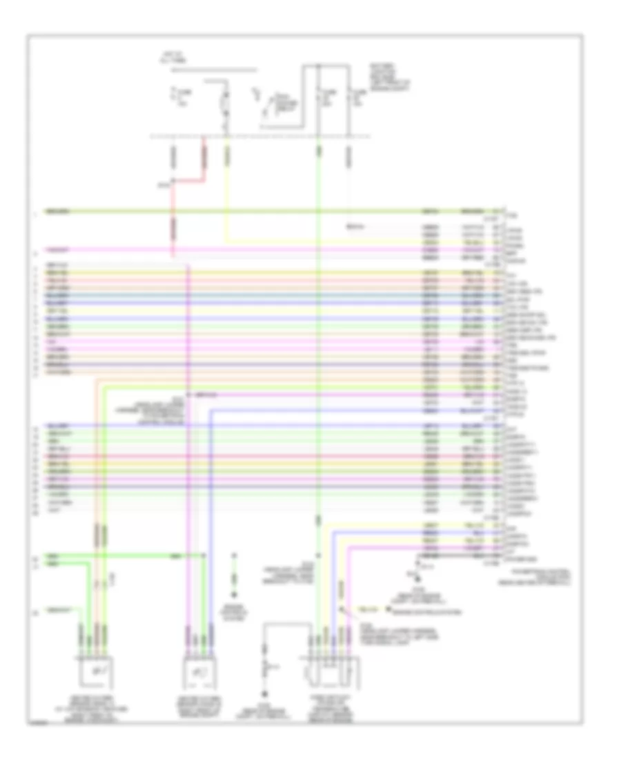
2.5L, A/T Wiring Diagram for Ford Escape 2011
List of elements for 2.5L, A/T Wiring Diagram for Ford Escape 2011:
- (engine control wiring harness, near breakout to output shaft speed sensor)
- (rear of engine compt, on firewall) g109
- 10a
- 15a
- 20a
- Battery junction box (bjb) (left front of engine compt)
- Bpp
- Brake pedal position switch (left side of dash)
- C133
- C168a
- C168b
- C175b
- C175e
- C175t
- C210
- C212
- C2280d
- Cbb29
- Ccb08
- Ce233
- Ce235
- Ce302
- Cet05
- Cet06
- Cet07
- Cet08
- Cet09
- Cet10
- Cet18
- Cet25
- Cet34
- Cht
- Cylinder head temperature sensor
- Engine controls system
- Exterior lights system
- Floor shifter
- Fuse
- Fuse 15a
- G109 (rear of engine compt, on firewall)
- Gd122
- Heated oxygen sensor (ho2s) 11 (right front of engine, in exhaust)
- Heated oxygen sensor (ho2s) 12 (right front of engine, in exhaust)
- Ho2s 12
- Hot at all times
- Hot w/ pcm power relay energized
- Htr 12
- Iat
- Kapwr
- Le111
- Le448
- Le451
- Le452
- Lpc vfs
- Mafrtn
- Mafs
- Mass air flow/ intake air temperature (maf/iat) sensor (rear of engine)
- Oss
- Pcm power relay
- Pcmrc
- Power distribution system
- Power gnd
- Powertrain control module (pcm) (center rear of firewall)
- Re320
- Re405
- Re406
- Re407
- Ret24
- S111 (headlamp jumper wiring harness, near breakout to left front side lamp)
- S114
- S118 (engine control sensor & fuel charge wiring harness, before breakout to fuel injector 3)
- S121 (headlamp jumper harness, near breakout to powertrain control module)
- S136 (engine control & fuel charge wiring harness, before breakout
- S142 (headlamp jumper harness, near breakout to c139)
- S144
- S146
- S147
- Sbb05
- Sigrtnc
- Sigrtne
- Sigrtnt
- Smart junction box (sjb) (center of dash)
- Sol pwr
- Ssa cb1234 vfs
- Ssb c35r vfs
- Ssc cb26 vfs
- Ssd cblr/c456 vfs
- Ssd cblr/cb456 vfs
- Sse on/off sol
- Tcc vfs
- Tcs
- Tft
- Tft sig rtn
- To fuel injector 3)
- Trans- mission control switch
- Transmission
- Trs
- Trs/oss gnd
- Trs/oss pwr
- Trs/oss vpwr
- Tss
- Tss gnd
- Tss pwr
- Tss/oss/tr gnd
- Uo2s11
- Uo2sgref
- Uo2shtr
- Uo2spc11
- Uo2spct11
- Ve712
- Ve731
- Ve740
- Ve807
- Ve826
- Vet26
- Vet27
- Vet32
- Vet33
- Vpwr
2.5L HYBRID
2.5L Hybrid, 4WD Wiring Diagram for Ford Escape 2011
List of elements for 2.5L Hybrid, 4WD Wiring Diagram for Ford Escape 2011:
- 4x4 control module (under center console)
- Active torque control coupling solenoid (hybrid: under center rear of vehicle) (except hybrid: rear differential)
- C2280d
- Cbp35
- Ccf21
- Computer data lines system
- Fuse 10a
- G301 (under driver's seat)
- Gd182
- Gnd
- Hot at all times
- Hot in run and start
- Hs can +
- Hs can -
- Nca
- Pwr
- Rcf21
- Run/start
- S310 (hybrid)
- S311 (except hybrid)
- S314 (hybrid)
- S323 (except hybrid)
- Sbp11
- Smart junction box (sjb) (except hybrid: center of dash) (hybrid: below center of dash)
- Sol +
- Sol -
- Vdb04
- Vdb05
2.5L Hybrid, A/T Wiring Diagram for Ford Escape 2011
List of elements for 2.5L Hybrid, A/T Wiring Diagram for Ford Escape 2011:
- (dash panel to headlamp junction harness, near breakout to battery junction box)
- 10a
- Air conditioning control module (lower left front of engine)
- Battery junction box (bjb) (left rear of engine compt)
- C1457d
- C1458a
- C1458b
- C1458d
- C1458e
- C1469b
- C175b
- C175t
- C210
- C4227a
- C4227b
- Cbb24
- Ce302
- Computer data
- Computer data lines system
- Cto
- Cyb01
- Cyb02
- Cyb03
- Cyb04
- Cyb05
- Cybo3
- Cyd01
- Cyd02
- Cydo2
- Cyt08
- Dc int+
- Dc int-
- Dc/dc converter module (right side of engine compt)
- Dc/dc interlock+
- Dc/dc interlock-
- Dc/dc+
- Dc/dc-
- Dsdn1
- Dsdn2
- Fuse
- G106 (left rear of engine compt)
- Gd121
- Gnd
- Gsdn
- High voltage junction box
- Hot at all times
- Hs can+
- Hs can-
- Hv +
- Hv -
- Hv+
- Hv-
- Hvdc+
- Hvdc-
- Hvtmu+
- Hvtmu-
- Hyt03
- Hyt04
- Int+
- Int-
- Intlk in
- Intlk out
- Let56
- Let57
- Lines system
- Mect
- Motor electronics coolant temperature (mect) sensor (left front of engine compt)
- Msdn
- Pcm power relay
- Pcmrc
- Powertrain control module (pcm) (rear center of firewall)
- Re406
- Ret56
- Ret57
- S116
- S121
- S142 (dash panel to headlamp junction harness, near breakout to battery junction box)
- S143
- Sbb05
- Sigrtn
- Tbcm interlock+
- Tbcm interlock-
- Tgac
- Tmac
- Tr a1
- Tr a2
- Tr bvref1
- Tr bvref2
- Tr rtn1
- Tr rtn2
- Traction battery control module
- Transaxle control module (above transaxle)
- Transmission range (tr) sensor
- Vbatt
- Vdb04
- Vdb05
- Ve810
- Vet55
- Vet57
- Vmc02
- Vpwr
- Vyt05
- Vyt06
3.0L
3.0L, 4WD Wiring Diagram for Ford Escape 2011
List of elements for 3.0L, 4WD Wiring Diagram for Ford Escape 2011:
- 4x4 control module (under center console)
- Active torque control coupling solenoid (hybrid: under center rear of vehicle) (except hybrid: rear differential)
- C2280d
- Cbp35
- Ccf21
- Computer data lines system
- Fuse 10a
- G301 (under driver's seat)
- Gd182
- Gnd
- Hot at all times
- Hot in run and start
- Hs can +
- Hs can -
- Nca
- Pwr
- Rcf21
- Run/start
- S310 (hybrid)
- S311 (except hybrid)
- S314 (hybrid)
- S323 (except hybrid)
- Sbp11
- Smart junction box (sjb) (except hybrid: center of dash) (hybrid: below center of dash)
- Sol +
- Sol -
- Vdb04
- Vdb05
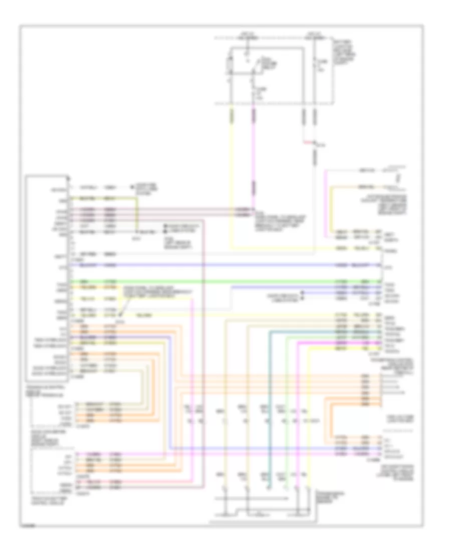
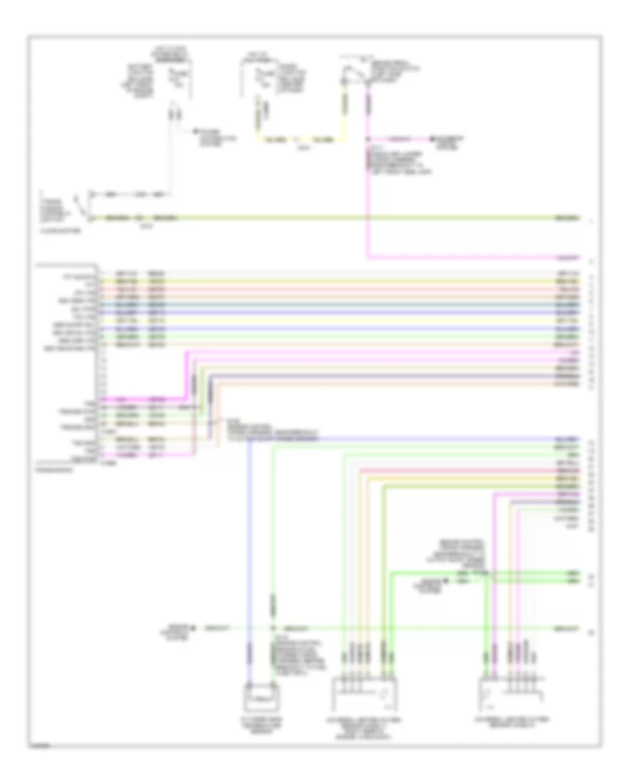
3.0L, A/T Wiring Diagram (1 of 2) for Ford Escape 2011
List of elements for 3.0L, A/T Wiring Diagram (1 of 2) for Ford Escape 2011:
- (engine control wiring harness, near breakout to output shaft speed sensor)
- Battery junction box (bjb) (left front of engine compt)
- Brake pedal position switch (left side of dash)
- C168a
- C168b
- C210
- C212
- C2280d
- Cet05
- Cet06
- Cet07
- Cet08
- Cet09
- Cet10
- Cet18
- Cet25
- Cylinder head temperature sensor
- Engine controls system
- Exterior lights system
- Floor shifter
- Fuse 10a
- Fuse 15a
- Hot at all times
- Hot w/ pcm power relay energized
- Le111
- Lpc vfs
- Oss
- Power distribution system
- Re406
- Ret24
- S120
- S146 (engine control wiring harness, near breakout to output shaft speed sensor)
- S147
- Sensor & fuel charge wiring harness, before breakout to fuel injector 3)
- Smart junction box (sjb) (center of dash)
- Sol pwr
- Ssa cb1234 vfs
- Ssb c35r vfs
- Ssc cb26 vfs
- Ssd cblr/c456 vfs
- Sse on/off sol
- Tcc vfs
- Tft
- Tft sig rtn
- Trans- mission control switch
- Transmission
- Trs
- Trs/oss gnd
- Trs/oss pwr
- Tss
- Tss gnd
- Tss pwr
- Universal heated oxygen sensor (ho2s) 11 (right rear of engine, in exhaust)
- Universal heated oxygen sensor (ho2s) 21
- Vet26
- Vet27
- Vet32
- Vet33
3.0L, A/T Wiring Diagram (2 of 2) for Ford Escape 2011
List of elements for 3.0L, A/T Wiring Diagram (2 of 2) for Ford Escape 2011:
- (rear of engine compt, on firewall)
- 10a
- 15a
- 20a
- Battery junction box (bjb) (left front of engine compt)
- Bpp
- C133
- C175b
- C175e
- C175t
- Cbb29
- Ccb08
- Ce233
- Ce234
- Ce235
- Ce236
- Ce302
- Cet05
- Cet06
- Cet07
- Cet08
- Cet09
- Cet10
- Cet18
- Cet25
- Cet34
- Cht
- Engine controls system
- Fuse
- G109
- G109 (rear of engine compt, on firewall)
- Gd122
- Heated oxygen sensor (ho2s) 12 (w/ low emission vehicles) (right front of engine, in exhaust)
- Heated oxygen sensor (ho2s) 22 (right front of engine compt)
- Ho2s 12
- Ho2s 22
- Hot at all times
- Htr 12
- Htr 22
- Iat
- Kapwr
- Le111
- Le448
- Le449
- Le450
- Le451
- Le452
- Le453
- Lpc vfs
- Maf
- Mafrtn
- Mass air flow/ intake air temperature (maf/iat) sensor (rear of engine)
- Oss
- Pcm power relay
- Pcmrc
- Power gnd
- Powertrain control module (pcm) (rear center of firewall)
- Re320
- Re405
- Re406
- Re407
- Ret24
- S114
- S121 (headlamp jumper harness, near breakout to powertrain control module)
- S128 (headlamp jumper harness, near breakout to left side turn signal lamp)
- S140
- S142 (headlamp jumper harness, near breakout to c139)
- S144
- Sbb05
- Sigrtn
- Sigrtnc
- Sol pwr
- Ssa cb1234 vfs
- Ssb c35r vfs
- Ssc cb26 vfs
- Ssd cblr/c456 vfs
- Sse on/off sol
- Tcc vfs
- Tcs
- Tft
- Trs
- Trs/oss vpwr
- Tss
- Tss/oss/tr gnd
- Uo2s11
- Uo2s21
- Uo2sgref11
- Uo2sgref21
- Uo2shtr11
- Uo2shtr21
- Uo2spc11
- Uo2spc21
- Uo2spct11
- Uo2spct21
- Ve712
- Ve731
- Ve733
- Ve740
- Ve807
- Ve826
- Ve827
- Vet26
- Vet27
- Vet32
- Vet33
- Vpwr

 Čeština
 Dansk
Dansk Deutsch
 Ελληνικά
 English
 English
 Español
 Suomi
Suomi Français
 Français
 עברית
עברית Hrvatski
 Magyar
 Italiano
 日本語
日本語 한국어
한국어 Nederlands
 Polski
 Português
 Português
 Română
 Русский
 Slovenčina
 Svenska
 Türkçe
 中文 (中国)