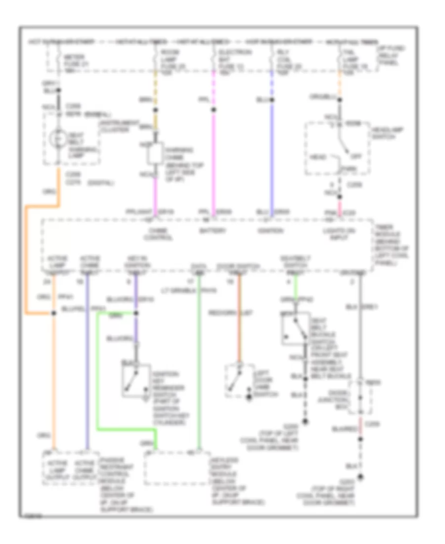
WARNING SYSTEMS
Warning System Wiring Diagrams for Mercury Villager GS 1995
List of elements for Warning System Wiring Diagrams for Mercury Villager GS 1995:
- (behind top left side of i/p)
- (digital)
- Active chime input
- Active chime output
- Active lamp output
- Battery
- C256
- C258
- C268 c276
- Chime control
- Data line
- Diode junction box
- Door switch input
- Electron bat fuse 13 10a
- G200 (top of left cowl panel, near door grommet)
- G203 (top of right cowl panel, near door grommet)
- Ground
- Head
- Headlamp switch
- Hot at all times
- Hot in run or start
- I/p fuse/ relay panel
- Ignition
- Ignition key reminder switch (part of ignition switch key cylinder)
- Instrument cluster
- Key in ignition input
- Keyless entry module (below center of i/p, on i/p support brace)
- Left door jamb switch
- Lights on input
- Meter fuse 21 10a
- Nca
- Off
- Park
- Passive restraint control module (below center of i/p, on i/p support brace)
- Pnk ic20
- Rly coil fuse 20 10a
- Room lamp fuse 25 15a
- Seat belt buckle switch (on left front seat assembly, near seat belt buckle
- Seat belt warning lamp
- Seatbelt switch input
- Tail lamp fuse 19 15a
- Timer module (behind bottom of left cowl panel)
- Warning chime
 Čeština
 Dansk
Dansk Deutsch
 Ελληνικά
 English
 English
 Español
 Suomi
Suomi Français
 Français
 עברית
עברית Hrvatski
 Magyar
 Italiano
 日本語
日本語 한국어
한국어 Nederlands
 Polski
 Português
 Português
 Română
 Русский
 Slovenčina
 Svenska
 Türkçe
 中文 (中国)
 Slovenščina