AIR CONDITIONING
2.0L
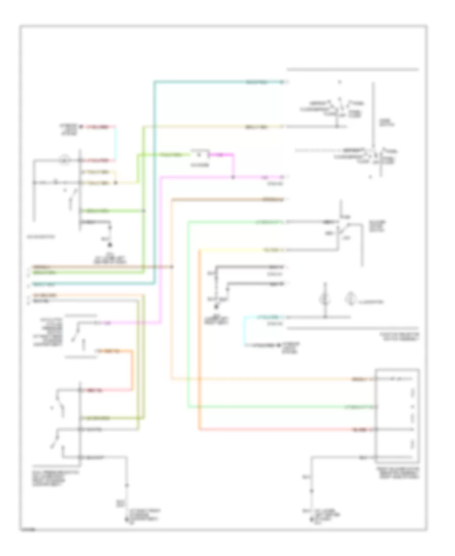
2.0L, Manual A/C Wiring Diagram (1 of 2) for Mazda Tribute i 2005
 https://portal-diagnostov.com/license.html
Automotive Electricians Portal FZCO
Automotive Electricians Portal FZCO
https://portal-diagnostov.com/license.html
https://portal-diagnostov.com/license.html
Automotive Electricians Portal FZCO
Automotive Electricians Portal FZCO
List of elements for 2.0L, Manual A/C Wiring Diagram (1 of 2) for Mazda Tribute i 2005:
- (at lower left center of dash) g14
- (at right front of engine compartment) g2
- (at right front of engine compartment) g5
- (at right front of engine compt) g5
- (behind left rear wheelwell) g20
- 0140-175b
- A/c clutch relay
- A/c clutch solenoid (at left front of engine)
- A/c compressor clutch diode
- Battery junction box (on left side of engine compartment)
- Blower motor relay (behind lower left center of dash)
- Cooling fan relay
- Engine controls system
- Engine cooling fan motor 1 (front of engine compt)
- Engine cooling fan motor 2 (front of engine compt)
- Front blower motor
- Fuse 15a
- Fuse 26 5a
- Fuse 30a
- Fuse 40a
- Fuse 5 2a
- High speed fan control relay 1
- Hot at all times
- Hot in on or start
- J-2280a
- J-2280b
- Low speed fan control relay
- Pcm power diode
- Pcm power relay
- Powertrain control module (pcm) (at upper center of firewall)
- Red
- Smart junction box (rear center of engine compt)
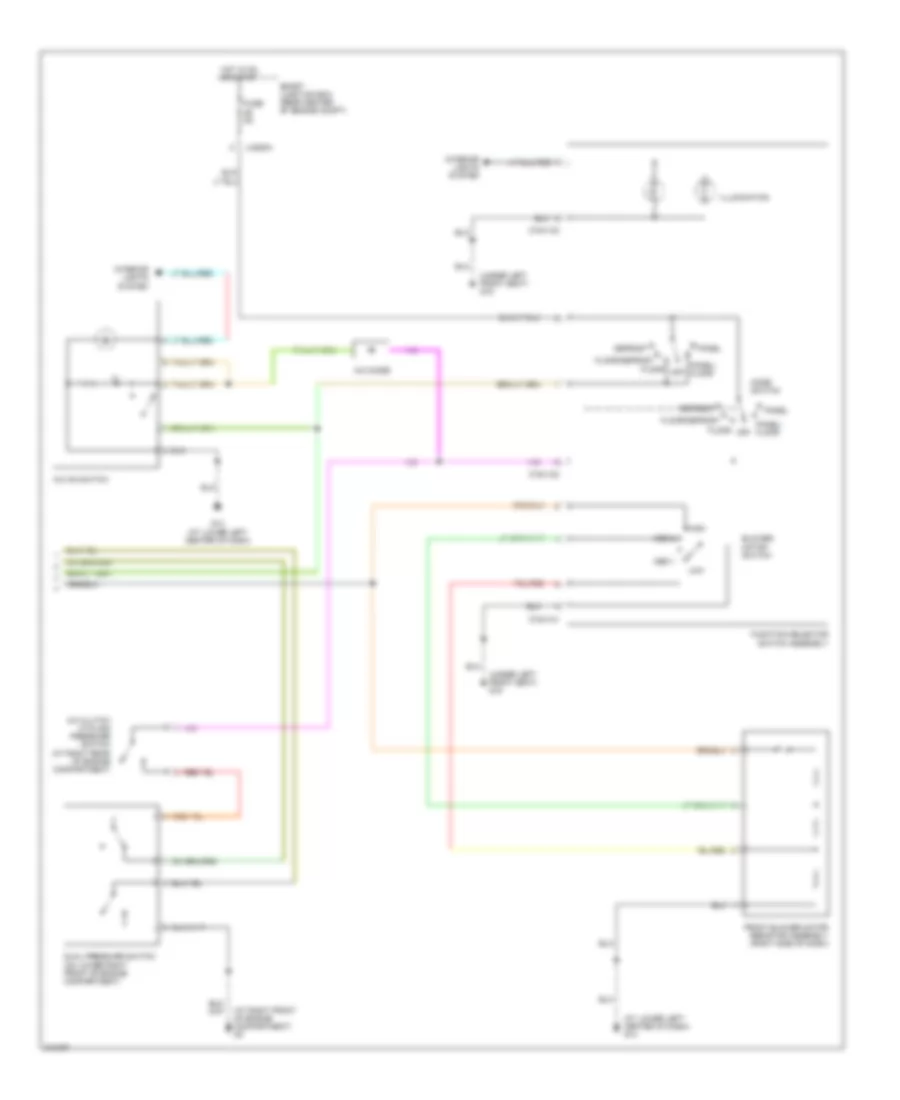
2.0L, Manual A/C Wiring Diagram (2 of 2) for Mazda Tribute i 2005
List of elements for 2.0L, Manual A/C Wiring Diagram (2 of 2) for Mazda Tribute i 2005:
- (at lower left center of dash) g14
- (at right front of engine compartment) g3
- 0740-101
- 0740-102
- 0740-103
- A/c clutch cycling pressure switch (at right rear of engine compartment)
- A/c diode
- A/c on switch
- Blower motor switch
- Defrost
- Dual pressure switch (on lower right front of engine compartment)
- Floor
- Floor/defrost
- Front blower motor resistor assembly (right side of dash)
- Function selector switch assembly
- G14 (at lower left center of dash)
- G15 (under left front seat)
- High
- Illumination
- Interior lights system
- Low
- Med 1
- Med 2
- Mode switch
- Off
- Panel
- Panel/ floor
3.0L
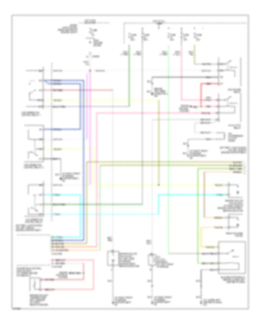
3.0L, Manual A/C Wiring Diagram (1 of 2) for Mazda Tribute i 2005
List of elements for 3.0L, Manual A/C Wiring Diagram (1 of 2) for Mazda Tribute i 2005:
- (at lower left center of dash) g14
- (at right front of engine compartment) g2
- (at right front of engine compartment) g5
- (behind left rear wheelwell) g20
- 0140-275b
- 0140-275e
- 87a
- A/c clutch relay
- A/c clutch solenoid (at left front of engine)
- A/c compressor clutch diode
- Battery junction box (on left side of engine compartment)
- Battery junction box (on left side of engine compartment)
- Blower motor relay (behind lower left center of dash)
- Engine control system
- Engine controls system
- Engine coolant temperature (ect) sensor (at right rear of engine)
- Engine cooling fan motor 1 (at left side of engine compartment, behind radiator)
- Engine cooling fan motor 2 (at right side of engine compartment, behind radiator)
- Front blower motor
- Fuse 15a
- Fuse 2a
- Fuse 30a
- Fuse 40a
- Fuse 50a
- High speed fan control relay 1
- High speed fan control relay 2
- Hot at all times
- Hot in on or start
- J-2280b
- Low speed fan control relay
- Pcm power diode
- Pcm power relay
- Powertrain control module (pcm) (at upper center of firewall)
- Red
- Smart junction box (rear center of) engine compt)
3.0L, Manual A/C Wiring Diagram (2 of 2) for Mazda Tribute i 2005
List of elements for 3.0L, Manual A/C Wiring Diagram (2 of 2) for Mazda Tribute i 2005:
- (at lower left center of dash) g14
- (at right front of engine compartment) g3
- (under left front seat) g15
- 0740-101
- 0740-102
- 0740-103
- A/c clutch cycling pressure switch (at right rear of engine compartment)
- A/c diode
- A/c on switch
- Blower motor switch
- Defrost
- Dual pressure switch (on lower right front of engine compartment)
- Floor
- Floor/defrost
- Front blower motor resistor assembly (right side of dash)
- Function selector switch assembly
- Fuse 5a
- G14 (at lower left center of dash)
- High
- Hot in on or start
- Illumination
- Interior lights system
- J-2280a
- Low
- Med 1
- Med 2
- Mode switch
- Off
- Panel
- Panel/ floor
- Smart junction box (rear center of engine compt)

 Čeština
 Dansk
Dansk Deutsch
 Ελληνικά
 English
 English
 Español
 Suomi
Suomi Français
 Français
 עברית
עברית Hrvatski
 Magyar
 Italiano
 日本語
日本語 한국어
한국어 Nederlands
 Polski
 Português
 Português
 Română
 Русский
 Slovenčina
 Svenska
 Türkçe
 中文 (中国)