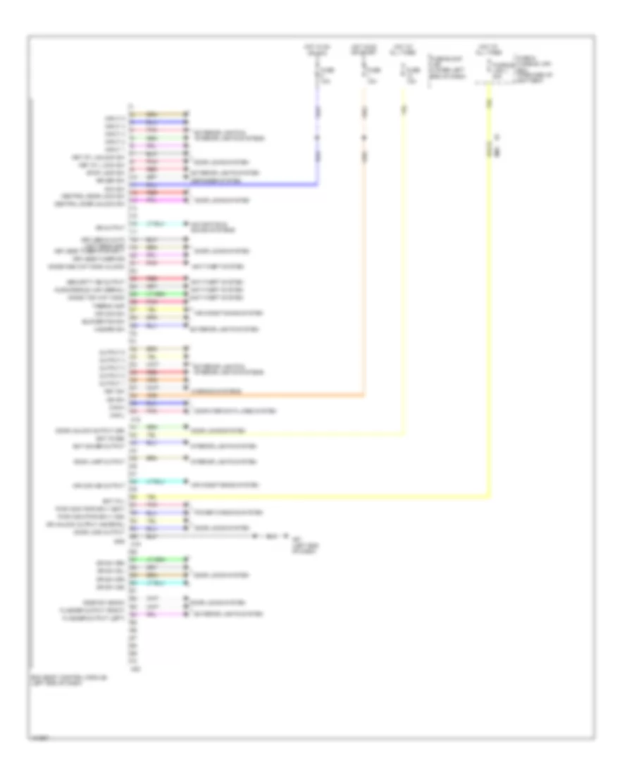
BODY CONTROL MODULES
Body Control Modules Wiring Diagram for Nissan NV200 Taxi 2014
List of elements for Body Control Modules Wiring Diagram for Nissan NV200 Taxi 2014:
- 91a
- Acc sw
- Air con ind output
- Air con sw
- Air conditioning system
- Anti-theft system
- Audo/dongle link (serial)
- Bat (f/l)
- Bat (fuse)
- Bat saver output
- Bcm (body control module) (left end of dash)
- Blower fan sw
- Can-h
- Can-l
- Central door lock sw
- Central door unlock sw
- Computer data lines system
- Defogger system
- Door lock output
- Door locks system
- Door sw (back)
- Door unlock output (dr)
- Dr sw (as)
- Dr sw (dr)
- Dr sw (rl)
- Dr sw (rr)
- Dr unlock output (as,rr,rl)
- Exterior lights & interior lights systems
- Exterior lights system
- Flasher output (left)
- Flasher output (right)
- Fuse & fusible link box (forward of battery)
- Fuse 10a
- Fuse block (j/b) (lower left end of dash)
- Fusible link j 40a
- Gnd
- Hazard sw
- Hot at all times
- Hot in on or acc
- Hot in on or start
- Ign sw
- Immob one way comm (clock)
- Immob two way comm
- Input 1
- Input 2
- Input 3
- Input 4
- Input 5
- Interior lights system
- Key cyl lock sw
- Key cyl unlock sw
- Key sw
- Keyless & auto light sens gnd
- Keyless tuner pwr sply
- Keyless tuner sig
- M18
- M19
- M20
- M61 (left end of dash)
- M69
- Mr output
- Navigation & sound systems
- Output 1
- Output 2
- Output 3
- Output 4
- Output 5
- Pnk
- Power windows system
- Pwr wdw pwr sply (bat)
- Pwr wdw pwr sply (ign)
- Red
- Room lamp output
- Rr def sw
- Security ind output
- Stop lamp sw
- Thermo amp
- Warning systems
 Čeština
 Dansk
Dansk Deutsch
 Ελληνικά
 English
 English
 Español
 Suomi
Suomi Français
 Français
 עברית
עברית Hrvatski
 Magyar
 Italiano
 日本語
日本語 한국어
한국어 Nederlands
 Polski
 Português
 Português
 Română
 Русский
 Slovenčina
 Svenska
 Türkçe
 中文 (中国)
 Slovenščina