CRUISE CONTROL
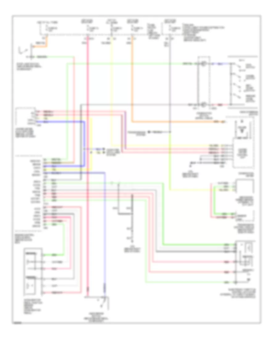
Cruise Control Wiring Diagram for Nissan Murano S 2007
List of elements for Cruise Control Wiring Diagram for Nissan Murano S 2007:
- Accelerator pedal position sensor (above accelerator pedal)
- Aps1
- Aps2
- Ascd brake switch (above brake pedal, on bracket)
- Ascd steering switch
- Ascd sw
- Avcc
- Avcc2
- Bncsw
- Brake
- Can-h
- Can-l
- Cancel switch
- Combination meter
- Combination switch (spiral cable)
- Computer data lines system
- Cruise ind
- E101 1c
- Electronic throttle control actuator (integral to throttle body, on intake manifold)
- Engine control module (ecm) (behind glove box)
- F101
- Fuse 12 10a
- Fuse 14 10a
- Fuse 20 10a
- Fuse 21 10a
- Fuse 83 10a
- Fuse block (j/b) (below left side of dash)
- Gnd
- Gnd-a
- Gnd-a2
- Gns-a
- Hot at all times
- Hot in on or start
- Ipdm e/r (intelligent power distribution module engine room) (right front of engine compartment, behind headlight)
- M203
- M25
- M31
- M49
- M78 (behind right end of dash)
- M80
- Main switch
- Motor 1
- Motor 2
- Nca
- Pnk
- Red
- Resume/ accel switch
- Secondary speed sensor (integral to cvt unit)
- Sensor
- Sensor 1
- Sensor 2
- Set ind
- Set/ coast switch
- Stop lamp switch (above brake pedal, on bracket)
- Tps1
- Tps2
- Transmission control module (behind right side of dash)
- Transmissions system
- Unified meter & a/c amplifier (behind lower center of dash)
- Unified meter control unit
 Čeština
 Dansk
Dansk Deutsch
 Ελληνικά
 English
 English
 Español
 Suomi
Suomi Français
 Français
 עברית
עברית Hrvatski
 Magyar
 Italiano
 日本語
日本語 한국어
한국어 Nederlands
 Polski
 Português
 Português
 Română
 Русский
 Slovenčina
 Svenska
 Türkçe
 中文 (中国)
 Slovenščina