TRANSMISSION
Transmission Wiring Diagram for Nissan NV200 Taxi 2014
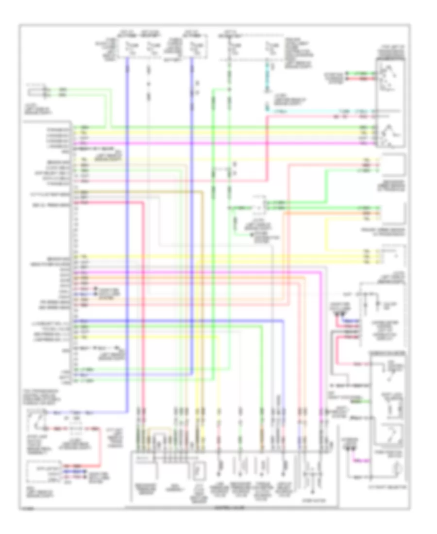
List of elements for Transmission Wiring Diagram for Nissan NV200 Taxi 2014:
- (not used)
- (top left of transmission) transmission range switch
- 15b
- 20b
- 38b
- 39b
- 92a
- Batt
- Can-h
- Can-l
- Chip select (sel1)
- Clock (sel2)
- Combination meter
- Computer data lines system
- Control valve
- Cvt fluid temp sens
- Cvt fluid temp- erature sensor
- Cvt shift selector
- Cvt unit (left rear of trans- mission)
- D range sw
- Data i/o (sel3)
- E16
- E41 (left rear of engine compt)
- E43
- Ecm (left rear of engine compt)
- F207
- F208
- Fuse & fusible link box (forward of battery)
- Fuse 10a
- Fuse block (j/b) (lower left end of dash)
- Gnd
- Hot at all times
- Hot in on or start
- Interior lights system
- Ipdm e/r (intelligent power distribution module engine room) (left rear of engine compt)
- J/c e01 (center rear of engine compt)
- J/c f01 (left side of engine compt)
- L range sw
- Line press sol vlv
- Line pressure solenoid valve
- Lock-up select solenoid valve
- Lu & select sol vlv
- M57 (right kick panel)
- M69 e7
- N range sw
- O/d control switch
- O/d off ind
- P range sw
- Park position switch
- Pnk
- Power distribution system
- Pri speed sens
- Primary speed sensor (in transmission)
- R range sw
- Red
- Rom assembly
- S/m-a
- S/m-b
- S/m-c
- S/m-d
- Sec oil press sens
- Sec press sol vlv
- Sec speed sens
- Secondary pressure sensor
- Secondary pressure solenoid valve
- Secondary speed sensor (in transaxle)
- Sens power source
- Sensor gnd
- Shift interlock system
- Shift lock solenoid
- Starting/ charging system
- Step motor
- Stop lamp switch (top of brake pedal assembly)
- Stp lmp sw
- Tcc sol valve
- Tcm (transmission control module) (forward of fuse & fusible link box)
- Torque converter clutch solenoid valve
- Unified meter control unit (w/ information display)
- Vign
 Čeština
 Dansk
Dansk Deutsch
 Ελληνικά
 English
 English
 Español
 Suomi
Suomi Français
 Français
 עברית
עברית Hrvatski
 Magyar
 Italiano
 日本語
日本語 한국어
한국어 Nederlands
 Polski
 Português
 Português
 Română
 Русский
 Slovenčina
 Svenska
 Türkçe
 中文 (中国)
 Slovenščina