ANTI-LOCK BRAKES
Anti-lock Brake Wiring Diagrams for Volkswagen GTI GLS 2000
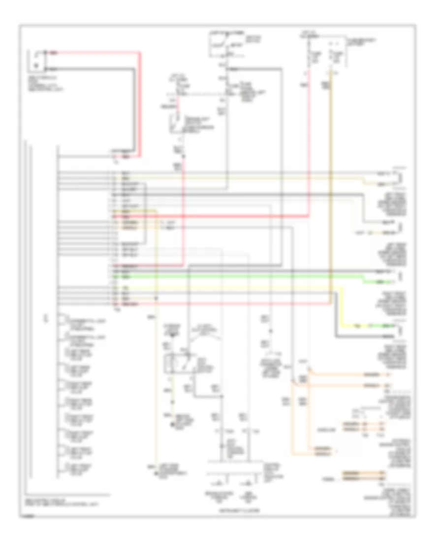
List of elements for Anti-lock Brake Wiring Diagrams for Volkswagen GTI GLS 2000:
- 13a
- 2.0l
- 2.8l
- Abs control module (part of abs hydraulic control unit)
- Abs hydraulic pump (integral with abs control unit)
- Abs warning ind
- Anti- slip control switch
- Anti- slip control warning ind
- Brake system warning ind
- Brakelight switch (above brake pedal)
- Control module with indicator unit
- Data link connector (under left side of dash)
- Diesel
- Diesel direct fuel injection engine control module (at base of windshield in center of plenum)
- Differential lock valve 1 (if equipped)
- Differential lock valve 2 (if equipped)
- Fuse 10a
- Fuse 30a
- Fuse 5a
- Fuse bracket/ battery
- Fuse panel (behind left side of dash)
- Gasoline
- Hot at all times
- Ignition switch
- Instrument cluster
- Interior lights system
- Left front abs inlet valve
- Left front abs outlet valve
- Left front abs wheel speed sensor (on left front hub/spindle assemble)
- Left rear abs inlet valve
- Left rear abs outlet valve
- Left rear abs wheel speed sensor (on left rear hub/spindle assemble)
- Lock
- Motronic engine control module (at base of windshield in center of plenum)
- Of engine compartment) g100
- Red
- Right front abs inlet valve
- Right front abs outlet valve
- Right front abs wheel speed sensor (on right front hub/spindle assemble)
- Right rear abs inlet valve
- Right rear abs outlet valve
- Right rear abs wheel speed sensor (on right rear hub/spindle assemble)
- Start
- T121
- T16
- T25
- T32
- T32a
- T68
- T80
- Transmission control module (at base of windshield in right side of plenum)
- W/ anti- slip control only
 Čeština
 Dansk
Dansk Deutsch
 Ελληνικά
 English
 English
 Español
 Suomi
Suomi Français
 Français
 עברית
עברית Hrvatski
 Magyar
 Italiano
 日本語
日本語 한국어
한국어 Nederlands
 Polski
 Português
 Português
 Română
 Русский
 Slovenčina
 Svenska
 Türkçe
 中文 (中国)
 Slovenščina