СИСТЕМА УПРАВЛЕНИЯ ДВИГАТЕЛЯ
2.8L
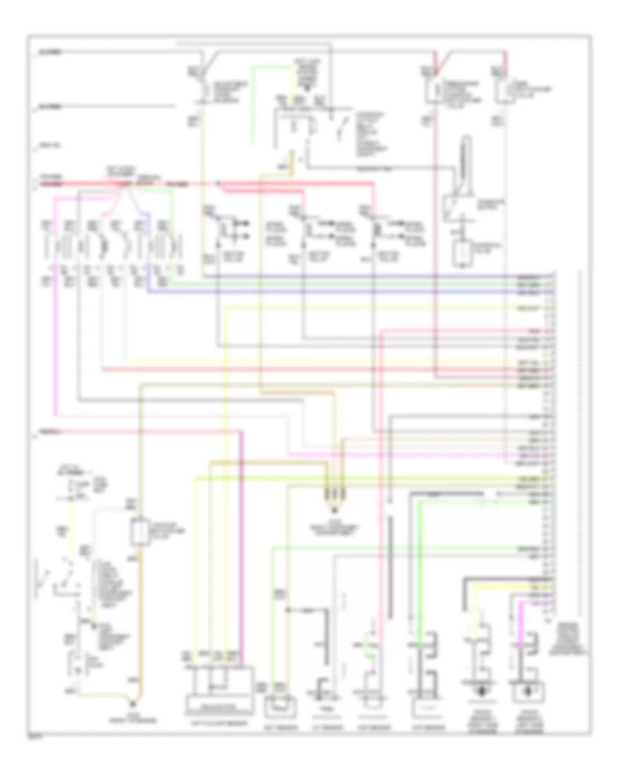
2.8L, Электросхема системы управления двигателя (1 из 2) для Mercedes-Benz C280 1995
 https://portal-diagnostov.com/license.html
Automotive Electricians Portal FZCO
Automotive Electricians Portal FZCO
https://portal-diagnostov.com/license.html
https://portal-diagnostov.com/license.html
Automotive Electricians Portal FZCO
Automotive Electricians Portal FZCO
2.8L, Электросхема системы управления двигателя (1 из 2) для Mercedes-Benz C280 1995 - Список элементов:
- (before
- (below center of trunk)
- (center rear of engine compt.)
- (in left component compt.)
- (in right component compt.)
- 15a
- 15u
- 30a
- 30z
- 30a
- 87e
- 87m
- 87u
- Asr/sps control module
- Cc/isc control module
- Check engine light 2f
- Cruise control system
- Data link connector (dtc readout) (in right component compt.)
- Diagnostic module (obd-ii)
- Diagnostic module (obd-ii) generic scan tool connector (right side of left footwell)
- Ea/cc/isc control module
- Engine control module (hfm-sfi) (in right component compt.)
- Fuel pump
- Fuel pump relay module
- Fuse 15a
- Fuse 7.5a
- Fuse box
- G104 (left component compartment)
- G105 (right component compartment)
- G405 (right rear wheelhouse)
- Hot at all times
- Instrument cluster
- Nca
- O2s 1
- O2s 2 (after twc)
- O2s 2 heater relay module (after twc)
- Overvoltage protection relay module (in right component compt.)
- Pnk/ red
- Pnk/red
- Purge control valve
- Rear fuse box
- Red
- Solid state
- Starter
- Terminal block
- Trans- mission overload protection switch
- Twc)
- Upshift delay switch- over valve
- W/ asr
- W/o asr
2.8L, Электросхема системы управления двигателя (2 из 2) для Mercedes-Benz C280 1995
2.8L, Электросхема системы управления двигателя (2 из 2) для Mercedes-Benz C280 1995 - Список элементов:
- (left side
- (right side
- Adjustable camshaft timing solenoid
- Air pump
- Air pump relay module (in left component compart- ment)
- Anti-lock brake system (speed signal)
- Ckp sensor
- Cmp sensor
- Ect sensor
- Egr switchover valve
- Engine control module (in right component compartment)
- Fuse 40a
- G104 (left component compart- ment)
- G105 (right component compartment)
- G125 (front of engine)
- Hot at all times
- Hot film maf sensor
- Hot in run or start
- Iat sensor
- Ignition coil #1
- Ignition coil #2
- Ignition coil #3
- Inj. #1
- Inj. #2
- Inj. #3
- Inj. #4
- Inj. #5
- Inj. #6
- Kickdown cut-out relay module (a/t) (in right component compt)
- Kickdown switch
- Kickdown valve
- Knock
- Maxi- fuse box
- Nca
- Of engine)
- Pnk
- Pnk/ red
- Pnk/red
- Resonance intake manifold switchover valve
- Sensor 1
- Sensor 2
- Solid state
- Spark plug #1
- Spark plug #2
- Spark plug #3
- Spark plug #4
- Spark plug #5
- Spark plug #6
- Switchover
- Terminal block
- Valve

 Čeština
 Dansk
Dansk Deutsch
 Ελληνικά
 English
 English
 Español
 Suomi
Suomi Français
 Français
 עברית
עברית Hrvatski
 Magyar
 Italiano
 日本語
日本語 한국어
한국어 Nederlands
 Polski
 Português
 Português
 Română
 Русский
 Slovenčina
 Svenska
 Türkçe
 中文 (中国)