STARTING/CHARGING
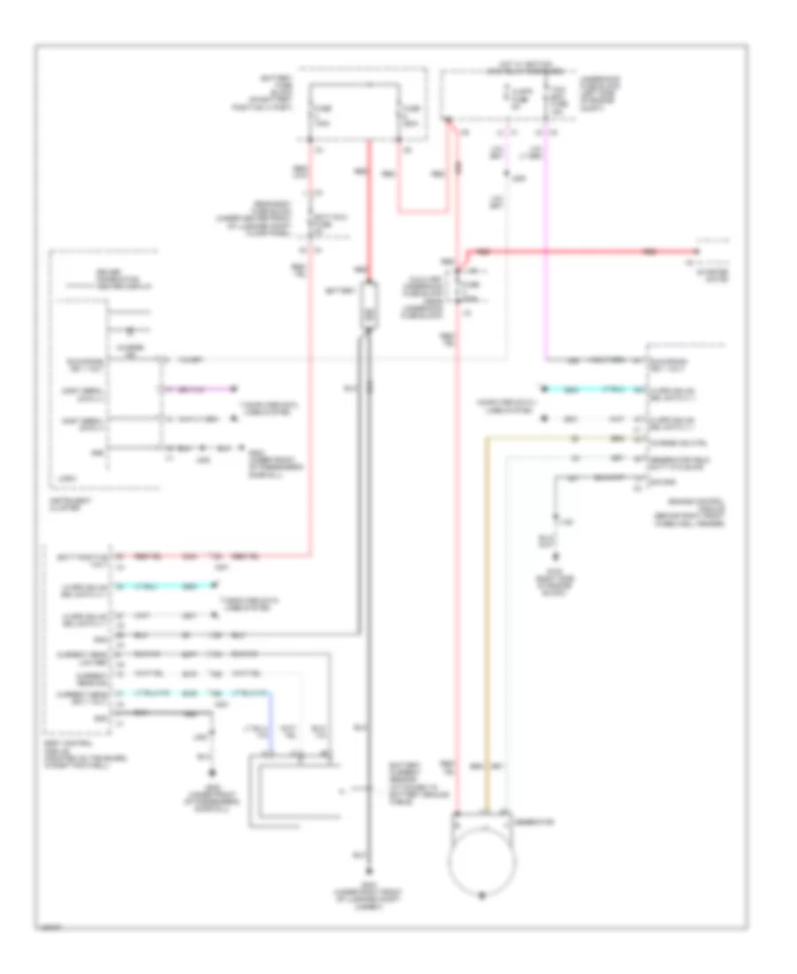
Charging Wiring Diagram for Chevrolet Corvette Stingray 2014
List of elements for Charging Wiring Diagram for Chevrolet Corvette Stingray 2014:
- Auxiliary underhood fuse block (near underhood fuse block)
- Batt positive volt
- Batt rvc fuse 5a
- Battery
- Battery current sensor (attached to battery ground cable)
- Battery fuse block (on battery positive (+) post)
- Body control module (mounted on toe board, in right footwell)
- Charge ind
- Charge ind ctrl
- Clstr fuse 5a
- Computer data lines system
- Current sens low ref
- Current sens sig
- Current sens sply volt
- Driver information center display
- Engine control module (behind right front wheelwell fender)
- Fuse 100a
- Fuse 225a
- Fuse 350a
- G100 (right side of engine block)
- G202 (under front of passenger's door sill)
- G303 (under right front of luggage compt carpet)
- Generator
- Generator field duty cycle sig
- Gnd
- Hi spd gmlan srl data (+) 1
- Hi spd gmlan srl data (-) 1
- Hot w/ ignition main relay energized
- Instrument cluster
- J120
- J209
- J238
- Logic
- Most serial data (+)
- Most serial data (-)
- Rear body fuse block (under center front of luggage compt floor panel)
- Red
- Run/crank ign 1 volt
- Sig gnd
- Starter motor
- Tcm/ ecm fuse 15a
- Underhood fuse block (left side of engine compt)
- X201
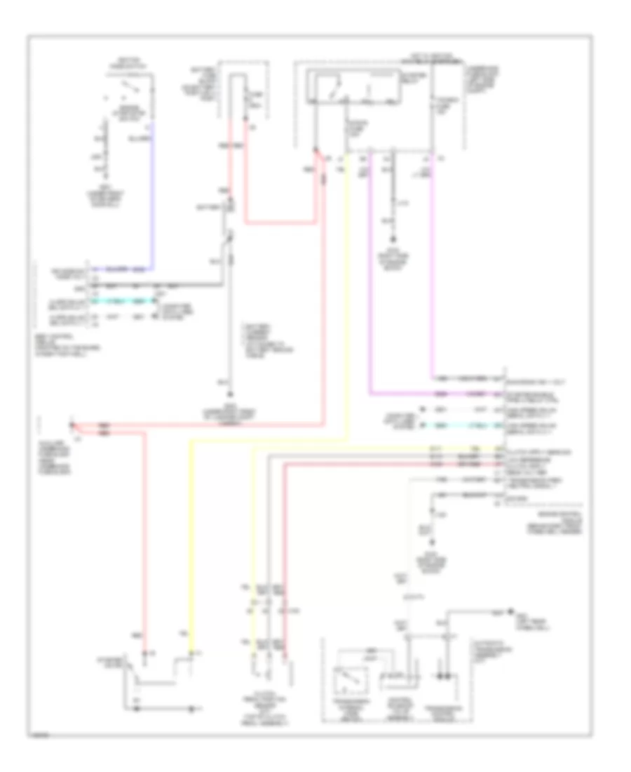
Starting Wiring Diagram for Chevrolet Corvette Stingray 2014
List of elements for Starting Wiring Diagram for Chevrolet Corvette Stingray 2014:
- Automatic transmission assembly (a/t)
- Auxiliary underhood fuse block (near underhood fuse block)
- Battery
- Battery current sensor (attached to battery ground cable)
- Battery fuse block (on battery positive (+) post)
- Body control module (mounted on toe board, in right footwell)
- Clutch pedal position sensor (m/t) (top of clutch pedal assembly)
- Computer data lines system
- Control solenoid valve assembly
- Engine control module (behind right front wheelwell fender)
- Engine start/stop switch
- Fuse 350a
- G100 (right side of engine block)
- G201 (under front of driver's door sill)
- G303 (under right front of luggage compt carpet)
- G401 (left rear wheelwell)
- Gnd
- Hi spd gmlan srl data (+) 1
- Hi spd gmlan srl data (-) 1
- High speed gmlan serial data (+) 1
- High speed gmlan serial data (-) 1
- Hot w/ ignition main relay energized
- Ign mode sw mode volt
- Ignition mode switch
- J118
- J120
- J200
- Low reference
- Red
- Run/crank ign 1 volt
- Sig gnd
- Starter enable (ppei 3) relay ctrl
- Starter motor
- Starter relay
- Strtr fuse 30a
- Tcm/ecm fuse 15a
- Transmission control module
- Transmission internal mode switch
- Transmission park/ neutral signal 1
- Underhood fuse block (left side of engine compt)
- X100
- X174
- X2 a
- X201
 Deutsch
 English
 English
 Español
 Français
 Nederlands
 Русский


